WO2022045290A1 - 電極触媒およびその製造方法、並びに燃料電池 - Google Patents
電極触媒およびその製造方法、並びに燃料電池 Download PDFInfo
- Publication number
- WO2022045290A1 WO2022045290A1 PCT/JP2021/031498 JP2021031498W WO2022045290A1 WO 2022045290 A1 WO2022045290 A1 WO 2022045290A1 JP 2021031498 W JP2021031498 W JP 2021031498W WO 2022045290 A1 WO2022045290 A1 WO 2022045290A1
- Authority
- WO
- WIPO (PCT)
- Prior art keywords
- catalyst
- fuel cell
- electrode
- transition metal
- nickel
- Prior art date
- Legal status (The legal status is an assumption and is not a legal conclusion. Google has not performed a legal analysis and makes no representation as to the accuracy of the status listed.)
- Ceased
Links
Images









Classifications
-
- B—PERFORMING OPERATIONS; TRANSPORTING
- B01—PHYSICAL OR CHEMICAL PROCESSES OR APPARATUS IN GENERAL
- B01J—CHEMICAL OR PHYSICAL PROCESSES, e.g. CATALYSIS OR COLLOID CHEMISTRY; THEIR RELEVANT APPARATUS
- B01J31/00—Catalysts comprising hydrides, coordination complexes or organic compounds
- B01J31/16—Catalysts comprising hydrides, coordination complexes or organic compounds containing coordination complexes
- B01J31/22—Organic complexes
-
- B—PERFORMING OPERATIONS; TRANSPORTING
- B01—PHYSICAL OR CHEMICAL PROCESSES OR APPARATUS IN GENERAL
- B01J—CHEMICAL OR PHYSICAL PROCESSES, e.g. CATALYSIS OR COLLOID CHEMISTRY; THEIR RELEVANT APPARATUS
- B01J37/00—Processes, in general, for preparing catalysts; Processes, in general, for activation of catalysts
- B01J37/04—Mixing
-
- B—PERFORMING OPERATIONS; TRANSPORTING
- B01—PHYSICAL OR CHEMICAL PROCESSES OR APPARATUS IN GENERAL
- B01J—CHEMICAL OR PHYSICAL PROCESSES, e.g. CATALYSIS OR COLLOID CHEMISTRY; THEIR RELEVANT APPARATUS
- B01J37/00—Processes, in general, for preparing catalysts; Processes, in general, for activation of catalysts
- B01J37/08—Heat treatment
-
- H—ELECTRICITY
- H01—ELECTRIC ELEMENTS
- H01M—PROCESSES OR MEANS, e.g. BATTERIES, FOR THE DIRECT CONVERSION OF CHEMICAL ENERGY INTO ELECTRICAL ENERGY
- H01M4/00—Electrodes
- H01M4/86—Inert electrodes with catalytic activity, e.g. for fuel cells
- H01M4/88—Processes of manufacture
-
- H—ELECTRICITY
- H01—ELECTRIC ELEMENTS
- H01M—PROCESSES OR MEANS, e.g. BATTERIES, FOR THE DIRECT CONVERSION OF CHEMICAL ENERGY INTO ELECTRICAL ENERGY
- H01M4/00—Electrodes
- H01M4/86—Inert electrodes with catalytic activity, e.g. for fuel cells
- H01M4/90—Selection of catalytic material
-
- H—ELECTRICITY
- H01—ELECTRIC ELEMENTS
- H01M—PROCESSES OR MEANS, e.g. BATTERIES, FOR THE DIRECT CONVERSION OF CHEMICAL ENERGY INTO ELECTRICAL ENERGY
- H01M4/00—Electrodes
- H01M4/86—Inert electrodes with catalytic activity, e.g. for fuel cells
- H01M4/96—Carbon-based electrodes
-
- H—ELECTRICITY
- H01—ELECTRIC ELEMENTS
- H01M—PROCESSES OR MEANS, e.g. BATTERIES, FOR THE DIRECT CONVERSION OF CHEMICAL ENERGY INTO ELECTRICAL ENERGY
- H01M8/00—Fuel cells; Manufacture thereof
- H01M8/10—Fuel cells with solid electrolytes
-
- Y—GENERAL TAGGING OF NEW TECHNOLOGICAL DEVELOPMENTS; GENERAL TAGGING OF CROSS-SECTIONAL TECHNOLOGIES SPANNING OVER SEVERAL SECTIONS OF THE IPC; TECHNICAL SUBJECTS COVERED BY FORMER USPC CROSS-REFERENCE ART COLLECTIONS [XRACs] AND DIGESTS
- Y02—TECHNOLOGIES OR APPLICATIONS FOR MITIGATION OR ADAPTATION AGAINST CLIMATE CHANGE
- Y02E—REDUCTION OF GREENHOUSE GAS [GHG] EMISSIONS, RELATED TO ENERGY GENERATION, TRANSMISSION OR DISTRIBUTION
- Y02E60/00—Enabling technologies; Technologies with a potential or indirect contribution to GHG emissions mitigation
- Y02E60/30—Hydrogen technology
- Y02E60/50—Fuel cells
-
- Y—GENERAL TAGGING OF NEW TECHNOLOGICAL DEVELOPMENTS; GENERAL TAGGING OF CROSS-SECTIONAL TECHNOLOGIES SPANNING OVER SEVERAL SECTIONS OF THE IPC; TECHNICAL SUBJECTS COVERED BY FORMER USPC CROSS-REFERENCE ART COLLECTIONS [XRACs] AND DIGESTS
- Y02—TECHNOLOGIES OR APPLICATIONS FOR MITIGATION OR ADAPTATION AGAINST CLIMATE CHANGE
- Y02P—CLIMATE CHANGE MITIGATION TECHNOLOGIES IN THE PRODUCTION OR PROCESSING OF GOODS
- Y02P70/00—Climate change mitigation technologies in the production process for final industrial or consumer products
- Y02P70/50—Manufacturing or production processes characterised by the final manufactured product
Definitions
- the present invention relates to an electrode catalyst, a method for producing the same, and a fuel cell obtained by the electrode catalyst.
- platinum catalysts have been widely used as electrode catalysts for fuel cells for both anodes and cathodes.
- platinum catalysts are expensive and depleted resources, the development of alternative catalysts has been actively studied. I came.
- Patent Document 1 metal sulfides containing sulfur and the like have been reported as excellent catalysts for both anode and cathode catalysts (Patent Document 2, Non-Patent Documents 1 and 2).
- the catalytic activity of metal sulfide changes depending on the type of metal and the ratio of metal to sulfur. From such a viewpoint, catalysts containing two or more different metals and sulfur have also been extensively studied (Non-Patent Document 3-5).
- Non-Patent Document 6 shows a carbon alloy catalyst (Carbon Alloy Catalyst) obtained by firing a precursor composed of iron phthalocyanine and a phenol resin, and synchrotron radiation analysis results thereof.
- an object of the present invention is to provide an electrode catalyst capable of exhibiting sufficient performance when used as a fuel cell.
- the present inventors applied a kind of heat treatment technique called carbonization to a metal complex in which two different metal ions were crosslinked by sulfur, so that two kinds of metals and sulfur remained. It has been found that a heterogeneous catalyst (dry distillation catalyst) is produced. Further, among the dry distillation catalysts, those having a hydrogen and nitrogen content within a certain range have greatly improved catalytic performance as compared with the metal complex that gives the dry distillation catalyst, and the catalyst is a hydrogen-oxygen fuel cell. It was confirmed that it functions as an electrode catalyst for both the anode and the cathode, and the present invention was completed.
- dry distillation catalyst dry distillation catalyst
- the present invention relates to the following [1] to [17].
- Particles containing the first transition metal M1, the second transition metal M2, carbon, hydrogen, nitrogen and sulfur as constituent elements, and the hydrogen content and the nitrogen content are both less than 1% by weight.
- the first transition metal M1 is one selected from the group consisting of Ni, Mn, Fe, Co, Cu, and Zn.
- the first transition metal M1 is Ni
- the conductive material is acetylene black, vulcan, ketjen black, black pearl, graphitized acetylene black, graphitized vulcan, graphitized ketchen black, graphitized black pearl, carbon nanotube, carbon nanofiber, carbon nanohorn, and carbon.
- a method for producing an electrode catalyst which comprises the following steps 1a and 2a: Step 1a: The following formula (1)
- M is Ru II , Rh III or Ir III .
- L represents a hexamethylbenzene group or a pentamethylcyclopentadienyl group.
- X represents a halogen atom or a hydrogen atom and a hydride ion. When X is a hydrogen atom and a hydride ion, X may form a bridge with Ni II .
- Y represents a halogen atom or H 2 O.
- l, m and n are 2 independently of each other. It is an integer of up to 4.
- R is an independently alkyl group having 1 to 5 carbon atoms.
- Z represents the charge of the complex and is 0 or 2+).
- Step 2a A step of carbonizing the mixture obtained in the step 1a.
- the conductive material is acetylene black, vulcan, ketjen black, black pearl, graphitized acetylene black, graphitized vulcan, graphitized ketchen black, graphitized black pearl, carbon nanotube, carbon nanofiber, carbon nanohorn, and carbon.
- a membrane electrode assembly having a cathode, an anode, and a proton conduction film arranged between the cathode and the anode, and any one or more selected from the group consisting of the cathode and the anode is described in [13]. ], Which is a membrane electrode assembly which is an electrode for a fuel cell.
- a fuel cell comprising the membrane electrode assembly according to the above [14].
- an electrode catalyst that can exhibit sufficient performance when used as a fuel cell and can be used for both an anode and a cathode. Further, by using the catalyst of the present invention, the catalytic reaction using hydrogen and oxygen can be controlled in a wide range.
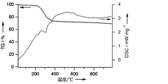
- FIG. 1 shows a differential heat-thermogravimetric simultaneous measurement TG-DSC curve of a mixture of [Ni II Cl (N 2 S 2 ) Rh III Cl ⁇ 5 -C 5 Me 5 ] and carbon black.
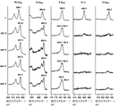
- FIG. 2 shows [Ni II Cl (N 2 S 2 ) Rh III Cl ⁇ 5 -C 5 Me 5 ] and its carbon black mixture and Ni II Cl (N 2 S 2 ) Rh III Cl ⁇ 5 -C 5 Me 5 ].
- the X-ray photoelectron spectroscopy (XPS) spectrum of the carbonization catalyst synthesized from is shown.
- FIG. 1 shows a differential heat-thermogravimetric simultaneous measurement TG-DSC curve of a mixture of [Ni II Cl (N 2 S 2 ) Rh III Cl ⁇ 5 -C 5 Me 5 ] and carbon black.
- FIG. 2 shows [Ni II Cl (N 2 S 2 ) Rh III Cl ⁇ 5 -C 5 Me 5 ] and its carbon black mixture and Ni II Cl (N 2 S 2 ) Rh
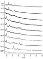
- FIG. 3 shows [Ni II Cl (N 2 S 2 ) Rh III Cl ⁇ 5 -C 5 Me 5 ], its carbon black mixture and Ni II Cl (N 2 S 2 ) Rh III Cl ⁇ 5 -C 5 Me 5 ].
- the X-ray diffraction (XRD) pattern of the carbonization catalyst and carbon black synthesized from is shown.
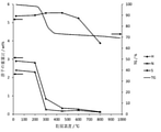
- FIG. 4 shows [Ni II Cl (N 2 S 2 ) Rh III Cl ⁇ 5 -C 5 Me 5 ] and a mixture thereof of carbon black and Ni II Cl (N 2 S 2 ) Rh III Cl ⁇ 5 -C 5 Me 5 ].
- the results of elemental analysis and thermogravimetric analysis (TG) of the carbonization catalyst synthesized from are shown.
- FIG. 5 shows [Ni II Cl (N 2 S 2 ) Rh III Cl ⁇ 5 -C 5 Me 5 ] and its carbon black mixture and Ni II Cl (N 2 S 2 ) Rh III Cl ⁇ 5 -C 5 Me 5 ].
- the results of (scanning) transmission electron microscope ((S) TEM) observation and energy dispersive X-ray spectroscopy (EDS) mapping of the dry distillation catalyst synthesized from the above are shown.
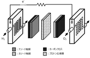
- FIG. 6 shows the configuration of the fuel cell used for the evaluation of the hydrogen-oxygen fuel cell.
- FIG. 7 shows the results of a hydrogen-oxygen fuel cell evaluation experiment using a nickel-rhodium carbonization catalyst prepared at 600 ° C. as an anode electrode catalyst.
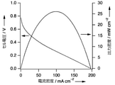
- FIG. 8 shows the results of a hydrogen-oxygen fuel cell evaluation experiment using a nickel-rhodium carbonization catalyst prepared at 600 ° C. as a cathode electrode catalyst.
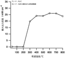
- FIG. 9 shows the results of the carbonization temperature dependence of the hydrogen-oxygen fuel cell evaluation experiment using the nickel-rhodium dry distillation catalyst as the anode electrode catalyst.
- FIG. 10 shows the results of the hydrogen-oxygen fuel cell evaluation experiment using the nickel-rhodium dry distillation catalyst as the cathode electrode catalyst, depending on the dry distillation temperature.
- FIG. 11 shows the results of a hydrogen-oxygen fuel cell evaluation experiment using a nickel-rhodium carbonization catalyst prepared at 600 ° C. as an electrode catalyst for both the anode and the cathode.
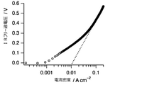
- FIG. 12 shows the results of a Tafel plot of a hydrogen-oxygen fuel cell using a mixture of [Ni II Cl (N 2 S 2 ) Rh III Cl ⁇ 5 -C 5 Me 5 ] and its carbon black as an anode electrode catalyst.
- FIG. 13 shows the results of a Tafel plot of a hydrogen-oxygen fuel cell using a nickel-rhodium carbonization catalyst prepared at 600 ° C. as an anode electrode catalyst.
- FIG. 14 shows the results of a Tafel plot of a hydrogen-oxygen fuel cell using a mixture of [Ni II Cl (N 2 S 2 ) Rh III Cl ⁇ 5 -C 5 Me 5 ] and its carbon black as a cathode electrode catalyst.
- FIG. 15 shows the results of a Tafel plot of a hydrogen-oxygen fuel cell using a nickel-rhodium carbonization catalyst prepared at 600 ° C. as a cathode electrode catalyst.
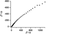
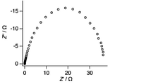
- FIG. 16 shows the impedance spectrum of a hydrogen-oxygen fuel cell using a mixture of [Ni II Cl (N 2 S 2 ) Rh III Cl ⁇ 5 -C 5 Me 5 ] and its carbon black as an anode electrode catalyst.
- FIG. 17 shows an impedance spectrum of a hydrogen-oxygen fuel cell using a nickel-rhodium carbonization catalyst prepared at 600 ° C. as an anode electrode catalyst.
- FIG. 18 shows the impedance spectrum of a hydrogen-oxygen fuel cell using a mixture of [Ni II Cl (N 2 S 2 ) Rh III Cl ⁇ 5 -C 5 Me 5 ] and its carbon black as a cathode electrode catalyst.
- FIG. 19 shows an impedance spectrum of a hydrogen-oxygen fuel cell using a nickel-rhodium carbonization catalyst prepared at 600 ° C. as a cathode electrode catalyst.
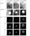
- Figure 20-1 shows the nickel-rhodium chloro complex [Ni II Cl (N 2 S 2 ) Rh III Cl ( ⁇ 5 -C 5 Me 5 )] (“complex 1”) and at 200 ° C and 230 ° C, respectively.
- FIG. 20-2 shows a bright field (BF) image obtained by TEM and an annular dark field (ADF) image obtained by STEM for each of the nickel-rhodium carbonization catalysts synthesized at 250 ° C., 280 ° C. and 300 ° C., respectively.
- the results of EDS mapping of each element (Rh, Ni, S) obtained by the EDS method are shown.
- the electrode catalyst according to the present invention is An electrode catalyst containing a catalyst component containing a first transition metal M1 and a second transition metal M2 as constituent elements and a conductive material. It is a particle containing the first transition metal M1, the second transition metal M2, carbon, hydrogen, nitrogen and sulfur as constituent elements.
- the first transition metal M1 is any one selected from the group consisting of Ni, Mn, Fe, Co, Cu, and Zn.
- the first transition metal M1 is Ni.
- the second transition metal M2 is usually a transition metal different from the first transition metal M1, and is composed of Ru, Rh, Pd, Ag, Ir, and Pt in a preferred embodiment of the present invention. It is one of the choices from the group.
- the second transition metal M2 is one selected from the group consisting of Ru, Rh, and Ir.
- both the hydrogen content and the nitrogen content in the particles are less than 1% by weight. This is because even if the particles contain the first transition metal M1, the second transition metal M2, carbon, hydrogen, nitrogen and sulfur as constituent elements, both the hydrogen content and the nitrogen content are less than 1% by weight. It is based on the findings of the present inventors that a significantly higher electric power density was obtained in the particles, when used as an electrode catalyst for a fuel cell, as compared with other particles.
- the hydrogen content is preferably 0.90% by weight or less, more preferably 0.50% by weight or less, and more preferably 0.30% by weight, from the viewpoint of obtaining a higher power density. The following is particularly preferable.
- the lower limit of the hydrogen content is not particularly limited as long as the effect of the present invention can be exhibited, but is preferably 0.01% by weight or more, and more preferably 0.10% by weight or more.
- the nitrogen content is preferably 0.30% by weight or less, more preferably 0.25% by weight or less, and 0.22% by weight or less from the viewpoint of obtaining a higher power density. Is particularly preferable.
- the lower limit of the nitrogen content is not particularly limited as long as the effect of the present invention can be exhibited, but is preferably 0.01% by weight or more, and more preferably 0.10% by weight or more. Further, in the present invention, the particles tend to have a low content of hydrogen and nitrogen but a relatively high content of sulfur.
- the sulfur content when the sulfur content is significantly higher than the hydrogen and nitrogen contents, a high power density tends to be obtained, for example, 5 times or more, preferably 10 times or more the hydrogen content. It is more than double, more preferably 15 times or more.
- the sulfur content is 10 times or more, preferably 20 times or more the nitrogen content.
- the specific numerical value of the sulfur content is not particularly limited as long as the effect of the present invention can be exhibited. However, the specific lower limit is preferably 2% by weight or more, and more preferably 3% by weight or more. On the other hand, although the specific upper limit value is not particularly limited, it is often 10% by weight or less, for example, 8% by weight or less.
- the sulfur content is, but is not limited to, 3 to 6% by weight.
- the content of each element constituting the particles can be determined by elemental analysis.
- a sulfide of the first transition metal M1 and a second transition metal M2 are observed. This has also been confirmed in Examples described later (see, for example, the description of "III. Identification of carbonization catalyst” in “Examples” below).
- a sulfide of the first transition metal M1 and a metallic second transition metal M2 are observed on the surface of the particles.
- a sulfide of the second transition metal M2 is further observed on the surface of the particles.
- the surface of the particles has a sulfide of a first transition metal M1, a sulfide of a metallic second transition metal M2 and a sulfide of a second transition metal M2.
- the "metal state” means that the valence of the target metal is zero.
- the presence of sulfide of the first transition metal M1 can be confirmed by XRD and XPS.
- the presence of the second transition metal M2 in a metallic state can be confirmed by XRD and XPS.
- the presence of the sulfide of the second transition metal M2 can be confirmed by XRD.
- Such an electrode catalyst can also be seen as a composite catalyst containing a catalyst component containing a first transition metal M1, a second transition metal M2, carbon, hydrogen, nitrogen and sulfur as constituent elements, and a conductive material. ..
- the catalyst component comprises a first transition metal M1 having an organic ligand containing hydrogen and nitrogen as constituent atoms, a second transition metal M2, and the first transition metal. It is a heat-treated product obtained by drying and distilling an organic metal complex containing a sulfur atom linking a transition metal M1 and the second transition metal M2.
- the electrode catalyst of the present invention also contains a conductive material.
- the conductive material constituting the electrode catalyst of the present invention include acetylene black, vulcan, ketjen black, black pearl, graphitized acetylene black, graphitized vulcan, graphitized ketchen black, graphitized black pearl, and carbon nanotube. , Carbon nanofibers, carbon nanohorns, and carbon fibrils.
- the conductive material used in the present invention may be one kind alone or a combination of two or more kinds.
- the content of the conductive material in the electrode catalyst of the present invention is not particularly limited as long as the effect of the present invention can be obtained, but is usually 1% by weight or more and 99% by weight or less with respect to the total amount of the electrode catalyst.
- the electrode catalyst of the present invention is obtained by the production method A described later, it is considered that the content of the conductive material in the obtained electrode catalyst is higher than the content of the conductive material in the mixture obtained in step 1 described later.
- the conductive material and the metal complex represented by the following formula (A) are used in the same amount in step 1, the amount of the conductive material in the obtained electrode catalyst is obtained from the metal complex.
- the lower limit of the content of the conductive material in the electrode catalyst of the present invention is preferably 30% by weight or more, more preferably 50% by weight or more.
- the upper limit is preferably 80% by weight or less, more preferably 70% by weight or less.
- the electrode catalyst according to the present invention is, for example, Sulfur linking a first transition metal M1 having an organic ligand containing hydrogen and nitrogen as constituent atoms, a second transition metal M2, and the first transition metal M1 and the second transition metal M2.
- the process of mixing an organic metal complex containing an atom with a conductive material to obtain a mixture and It can be obtained by a production method including a step of carbonizing the mixture.
- the sulfur atom is contained in the organic ligand. That is, the organic ligand contains hydrogen, nitrogen and sulfur as constituent atoms, and the sulfur constituting the organic ligand contains the first transition metal M1 and the second transition metal M2. It is preferable that they are linked. Examples of molecules constituting such an organic ligand are an amine having two or more ⁇ -mercaptoalkyl groups, an alkylenediamine having two or more ⁇ -mercaptoalkyl groups, and a polyalkyleneimine having two or more ⁇ -mercaptoalkyl groups. And so on.
- the nitrogen atoms constituting the amine, the alkylenediamine and the polyalkyleneimine are independently bonded to an alkyl group such as a methyl group.
- the polyalkyleneimine having two or more ⁇ -mercaptoalkyl groups is a linear polyalkyleneimine in which one ⁇ -mercaptoalkyl group is bonded to nitrogen atoms at both ends. Examples thereof include N, N'-dimethyl-3,7-diazanonan-1,9-dithiol.
- first transition metal M1 and the second transition metal M2 constituting the organometallic complex are the same as those described above in the section of the "electrode catalyst".
- it tends to be easy to control the catalytic ability of the obtained electrode catalyst by changing the metal species and ligands constituting the organic metal complex.
- it is possible to change the catalytic ability of the obtained electrode catalyst.
- the manufacturing method is a manufacturing method A including the following steps 1 and 2.
- Step 1 The following formula (A) (In formula (A), M1 is the first transition metal M1 and M2 is the second transition metal M2.
- L, X and Y represent suitable ligands, where X is. It may form a bridge with M1.
- L, m and n are independently integers of 2 to 4.
- R is an independent alkyl group having 1 to 5 carbon atoms.
- Z is an alkyl group having 1 to 5 carbon atoms.
- Step 2 A step of carbonizing the mixture obtained in the above step 1.
- the manufacturing method A is a manufacturing method A1 including the following steps 1a and 2a:
- Step 1a The following formula (1)
- M is Ru II , Rh III or Ir III .
- L represents a hexamethylbenzene group or a pentamethylcyclopentadienyl group.
- X represents a halogen atom or a hydrogen atom and a hydride ion. When X is a hydrogen atom and a hydride ion, X may form a bridge with Ni II .
- Y represents a halogen atom or H 2 O.
- l, m and n are 2 independently of each other. It is an integer of up to 4.
- R is an independently alkyl group having 1 to 5 carbon atoms.
- Z represents the charge of the complex and is 0 or 2+).
- Step 2a A step of carbonizing the mixture obtained in the step 1a.
- the metal complex of (1) above is N, N'-dimethyl-3,7-diazanonan-1,9- as an organic ligand coordinated to a Ni atom.
- Dithiolate ligand (corresponds to the case where the l and n are 2, the m is 3, and R is a methyl group. In the present specification, it may be referred to as “N 2 S 2 ”).
- Each of the above L has a pentamethylcyclopentadienyl group.
- the halogen atom that can constitute X and Y is preferably a chlorine atom.
- the M is preferably Rh III .
- the metal complex of (1) above can be obtained by using a conventionally known method, for example, Inorg. Chem. , 1990, 4779-4788, Inorg. Chem. 1990, 29, 2023-2025, Org. Let. 2004,6,2785-2788, Science 2007,316,585-587, Angew. Chem. Int. Ed. It can be obtained by referring to the methods described in 2013, 56, 9723-9726, JP-A-2017-132671 and the like.
- the step of obtaining the mixture can be carried out by a conventionally known method, including step 1 in the manufacturing method A and step 1a in the manufacturing method A1.
- the conductive material to be blended together with the metal complex represented by the above formula (A) or the above formula (1) and contained in the mixture is the same as the above-mentioned conductive material in the section of the above-mentioned "electrode catalyst". The same is true.
- the step of carbonizing the mixture is performed as a step of heat-treating the mixture, including step 2 in the manufacturing method A and step 2a in the manufacturing method A1.
- the organic metal complex contained in the mixture is thermally decomposed, and the volatile component containing hydrogen as a constituent element and the volatile component containing nitrogen as a constituent element are desorbed.
- thermal decomposition may start from around 220 ° C.
- the sulfur-containing component derived from the organic metal complex tends to be relatively difficult to desorb even under the temperature conditions under which the volatile component containing hydrogen as a constituent element and the volatile component containing nitrogen as a constituent element are desorbed. ..
- the carbonization can usually be carried out under vacuum or in an atmosphere such as nitrogen or argon, and is preferably carried out under vacuum from the viewpoint of removing decomposition products.
- the degree of the vacuum is usually 10 to 20 Pa.
- the temperature at which the carbonization is performed is not particularly limited as long as the catalyst obtained by the carbonization (hereinafter referred to as "carbonization catalyst”) can exert the effect of the present invention.
- carbonization catalyst the higher the temperature at which the carbonization is performed, the lower the hydrogen content and the nitrogen content in the obtained carbonization catalyst tend to be.
- a carbonization catalyst having a somewhat low hydrogen content and a low nitrogen content can obtain a high power density when used as an electrode catalyst for a fuel cell, which is advantageous.
- the temperature for carbonization is usually 100 to 800 ° C.
- the temperature for carbonization is preferably 200 ° C. or higher, more preferably 300 ° C. or higher, still more preferably 600 ° C. or higher.
- the upper limit of the temperature for carbonization is usually 800 ° C. or lower, preferably 700 ° C. or lower.
- the temperature for carbonization is typically 300 to 800 ° C, preferably 400 to 800 ° C.
- an electrode catalyst satisfying the above-mentioned requirements in the above-mentioned "electrode catalyst" section can be obtained.
- the carbonization catalyst obtained by the above production method can be used as an electrode catalyst.
- the electrode catalyst according to the present invention described above can be used for an electrode for a fuel cell. That is, the electrode for a fuel cell according to the present invention includes the above-mentioned electrode catalyst.
- the electrode for a fuel cell according to the present invention does not prevent the electrode from being composed of only the above-mentioned electrode catalyst as long as it can maintain a certain shape, but if necessary, a component other than the above-mentioned electrode catalyst (hereinafter, “other component””. ) May be contained.
- “other component” are catalyst carriers such as Balkan (manufactured by Cabot), carbon black, acetylene black, furnace black, graphite, carbon nanotubes, carbon nanofibers, black smoke, carbon fibers and activated carbon; Conductive polymers such as polyacetylene, polypyrrole, polythiol, polyimidazole, polypyridine, polyaniline and polythiophene can be mentioned.
- the amount of the electrode catalyst is 100 parts by weight
- the amount of "other components" is preferably 0 parts by weight or more and 50 parts by weight or less in the catalyst carrier, and in the conductive polymer. Is preferably 0 parts by weight or more and 50 parts by weight or less.
- the electrode for a fuel cell according to the present invention is a laminate having a layer made of a conductive material having gas diffusivity (hereinafter referred to as “gas diffusion layer”) and a layer made of the electrode catalyst (hereinafter referred to as “catalyst layer”). It may be a body. This gas diffusion layer also has a role of supporting the catalyst layer.
- the gas diffusion layer may be any gas diffusion layer having electron conductivity, high gas diffusivity, and high corrosion resistance, but is generally a carbon-based porous material such as carbon paper or carbon cloth. The material is used.
- Such an electrode for a fuel cell is formed, for example, by adding an appropriate medium to the electrode catalyst to form a solution, suspension, slurry, paste, or the like, applying the solution to the gas diffusion layer, and drying the electrode.
- the medium for making the electrode catalyst into a solution, suspension, slurry, paste or the like is not particularly limited, and a conventionally known medium may be appropriately selected and used.
- the coating amount is preferably 0.1 to 10 mg / cm 2 , more preferably 0.5 to 5 mg / cm 2 .
- the catalyst layer may contain, if necessary, a catalyst carrier, a conductive polymer, an ionomer, or the like, in addition to the electrode catalyst.
- the catalyst carrier, conductive polymer, ionomer, etc. may be added to the solution, suspension, slurry, paste, etc. of the electrode catalyst, or the solution, suspension, slurry, paste, etc. of the electrode catalyst. Separately, it may be applied as a solution, suspension, solution, slurry, paste or the like before, simultaneously with, or after applying the catalyst layer.
- an oxidation reaction of fuel occurs at an anode (also called a negative electrode or a fuel electrode), and a reduction of an oxidizing agent occurs at a cathode (also called a positive electrode or an air electrode).
- the electrode for a fuel cell according to the present invention may be an anode or a cathode. It may also be both an anode and a cathode. In a particularly preferred embodiment of the present invention, the fuel cell electrode is a cathode.
- the membrane electrode assembly according to the present invention is a membrane electrode assembly having a cathode, an anode, and a proton conduction film arranged between the cathode and the anode, and is composed of a cathode and an anode. Any one or more selected is the above-mentioned electrode for the fuel cell of the present invention.
- a conventionally known fuel cell electrode for example, a fuel cell electrode containing a platinum-based catalyst such as platinum-supported carbon can be used.
- the cathode is the electrode for a fuel cell of the present invention and the anode is a conventionally known electrode for a fuel cell.
- this gas diffusion layer is arranged on the opposite side of the layer made of the electrode catalyst when viewed from the proton conduction film. Will be done.
- the proton conducting membrane for example, an electrolyte membrane using a perfluorosulfonic acid system or a hydrocarbon-based electrolyte membrane is generally used.
- the proton conductive membrane include proton conductive polyelectrolytes such as Nafion (registered trademark), Flemion (registered trademark), and Aciplex (registered trademark).
- the membrane electrode assembly of the present invention can be appropriately formed by using a conventionally known method.
- the fuel cell of the present invention includes the membrane electrode assembly of the present invention described above.
- the fuel cell of the present invention further includes two current collectors in a manner of sandwiching a membrane electrode assembly.
- the fuel cell of the present invention has the above-mentioned electrode for the fuel cell of the present invention as a cathode, an anode, or both a cathode and an anode.
- the fuel cell electrode is a cathode.
- a fuel cell having the fuel cell electrode of the present invention as a cathode and a conventionally known fuel cell electrode as an anode is particularly preferable in that a high power density can be obtained.
- the fuel cell is the electrode for the fuel cell of the present invention described above. It is preferable to have it as both a cathode and an anode.
- the current collector can be a conventionally known one generally adopted for a fuel cell, and for example, as shown in FIG. 6, it has a shape of a current collector plate having a built-in flow path. be able to.
- the anode gas introduced from the outside of the fuel cell is supplied to the anode through the current collector arranged on the anode side, and the cathode gas introduced from the outside of the fuel cell is cathodeed through the current collector arranged on the cathode side.
- the anode gas is a gas that serves as a fuel, and is typically hydrogen.
- the anode gas is hydrogen, this hydrogen may be obtained by reforming gasoline, methanol, diethyl ether, hydrocarbon, or the like.
- the cathode gas may be methanol, diethyl ether or the like.
- the cathode gas introduced from the outside of the fuel cell is a gas serving as an oxidizing agent, and may be oxygen or air.
- the anode gas is hydrogen and the cathode gas is oxygen.
- the fuel cell of the present invention will be used as a hydrogen-oxygen type fuel cell.
- the present invention also provides a power generation method. This is based on the fact that the electrode catalyst of the present invention is inexpensive and the catalytic capacity can be easily controlled when used as an electrode for a fuel cell.
- the power generation method according to the present invention includes a step of performing an oxidation reaction of fuel using the above-mentioned electrode catalyst and / or a step of carrying out a reduction reaction of an oxidizing agent using the above-mentioned electrode catalyst. That is, the power generation method according to the present invention may include both a step of performing an oxidation reaction of the fuel using the electrode catalyst and a step of performing a reduction reaction of the oxidant using the electrode catalyst. Or may include either one.
- a step of releasing electrons from hydrogen molecules to form hydrogen ions using the electrode catalyst for a fuel cell and / or the electrode catalyst for a fuel cell is used. It comprises the steps of reacting oxygen molecules, hydrogen ions and electrons to produce water.
- the power generation method according to the present invention may be performed by a conventionally known method and is not particularly limited, but to explain an example, hydrogen gas is supplied to the anode side of the fuel cell and oxygen is supplied to the cathode side. At this time, hydrogen gas and oxygen may be humidified through a bubbler.
- the hydrogen gas When hydrogen gas is supplied from the anode side, the hydrogen gas emits electrons from the hydrogen molecules by the action of the electrode catalyst for the fuel cell and becomes hydrogen ions. This hydrogen ion passes through the electrolyte membrane and moves to the opposite cathode. At the cathode, due to the action of the electrode catalyst for a fuel cell, the transferred hydrogen ions react with oxygen molecules supplied to the cathode to generate water. At this time, the flow of electrons generated in the electric wire is taken out as a direct current.
- Ni II N 2 S 2
- N 2 S 2 N, N'-dimery-3, 7-diazananone-1, 9-ditholato
- H 2 gas and O 2 gas were purchased from Taiyo Toyo Oxygen Co., Ltd.
- H 2 O was purchased from Wako Pure Chemical Industries, Ltd. These were used without further purification.
- the ultraviolet visible spectrum was measured at 25 ° C. with a Japan spectroscopic V-670 UV-Visible-NIR spectrometer (cell length 0.1 cm).
- GC-MS Gas chromatography-mass spectrometry
- TG-DSC differential heat-thermogravimetric measurement
- TG-DSC Differential thermal-thermogravimetric simultaneous measurement
- XPS X-ray photoelectron spectroscopy
- Elemental analysis data were obtained with the Yanaco CHN-coder MT-5 and PerkinElmer 2400 II series CHNS / O analyzers.
- the sample was then heated under reduced pressure (15-20 Pa) for 1 hour. Heating starts when the temperature rises from room temperature, and after reaching the target temperature (hereinafter referred to as "carbonization temperature") (the time required from room temperature to the carbonization temperature is within about 5 minutes), 1 at this temperature. This was done by carbonizing the time. After heating, the decompression in the device was released, the sample was taken out from the device, the sample was cooled to room temperature in the atmosphere outside the device, and the sample was taken out from the device. The obtained sample was used as a nickel-rhodium carbonization catalyst in the following examples. The same synthesis was repeated while changing the carbonization temperature within the range of 100-800 ° C.
- Example 1-2 Synthesis of nickel / iridium dry distillate catalyst using nickel / iridium chloro complex [Ni II Cl (N 2 S 2 ) Ir III Cl ( ⁇ 5 -C 5 Me 5 )] Nickel / iridium chloro complex Nickel-iridium chloro complex [Ni II Cl (N 2 S 2 ) Ir III Cl ( ⁇ 5 -C 5 Me 5 )] (hereinafter sometimes referred to as "nickel-iridium chloro complex" or "NiIr complex”.
- nickel-iridium chloro complex Nickel-iridium chloro complex
- Example 1-3 A nickel-ruthenium hydride complex [Ni II (H 2 O) (N 2 S 2 ) ( ⁇ -H) Ru II ( ⁇ 6 -C 6 Me 6 )] (NO 3 ) was used. Synthesis of nickel-ruthenium dry distillate catalyst Instead of nickel-rodium chloro complex, nickel-ruthenium hydride complex [Ni II (H 2 O) (N 2 S 2 ) ( ⁇ -H) Ru II ( ⁇ 6 -C 6 Me 6 ) ] (NO 3 ) (hereinafter sometimes referred to as "nickel-ruthenium hydride complex" or "NiRu complex”) was used, but the same dry distillation catalyst synthesis experiment as in Example 1-1 was carried out.
- FIG. 1 shows the results of TG-DSC measurement. From the TG-DSC curve shown in FIG. 1, weight loss of the sample accompanied by an endothermic reaction was observed from around 220 ° C., and it was clarified that the decomposition of the nickel-rhodium chloro complex started from the above temperature.
- FIG. 2 The result of XPS is shown in FIG. In FIG. 2, "1" represents a nickel-rhodium chloro complex.
- the results in Figure 2 show that: * In the nickel-rhodium chloro complex (“1”) before carbonization, a peak that can be attributed to trivalent Rh and a peak that can be attributed to divalent Ni were observed. * In the nickel-rhodium carbonization catalyst synthesized at 300 ° C. or higher, the peaks derived from N and the peaks derived from Cl almost disappear, and these elements are reduced by carbonization.
- Example 1-1 (2) Analysis of nickel-rhodium dry distillate catalyst by XRD
- synthesis was performed at various dry distilling temperatures (100 ° C, 200 ° C, 300 ° C, 400 ° C, 500 ° C, 600 ° C, 700 ° C, 800 ° C).
- XRD measurements were performed on each of the nickel-rhodium dry distillate catalyst and the nickel-rhodium chloro complex [Ni II Cl (N 2 S 2 ) Rh III Cl ( ⁇ 5 -C 5 Me 5 )].
- the XRD measurement was carried out using a nickel-rhodium carbonization catalyst or a mixture of nickel-rhodium chloro complex (5 mg) and carbon black (5 mg) as a sample. The result of XRD is shown in FIG.
- the present inventor infers as follows. In the carbonization catalyst obtained by carbonization at 200 ° C. or lower, a part of the nickel-rhodium chloro complex remains unreacted. The portion of this carbonization catalyst other than the unreacted nickel-rhodium chloro complex is considered to be in an amorphous state.
- the carbonization catalyst obtained by carbonization at 300 to 400 ° C. has a peak that is slightly similar to Ni 3S 2 but has not been completely identified. From this, it is considered that some solid that has not been identified exists in this carbonization catalyst.
- the carbonization catalyst obtained by carbonization at 600 ° C. is considered to be a state in which the solid found in the carbonization catalyst obtained by carbonization at 300 ° C. and a solid similar to Rh 17 S 15 are mixed.
- the carbonization catalyst obtained by carbonization at 700 ° C. the peak intensity of a solid similar to Rh 17 S 15 is weakened. It is considered that the carbonization catalyst obtained by carbonization at 800 ° C. produces a sulfur-doped RhNi alloy or a sulfur-doped Rh-like solid.
- Example 1-1 Elemental analysis of nickel-rhodium dry distillate catalyst
- -Elemental analysis was performed for each of the rhodium chloro complexes [Ni II Cl (N 2 S 2 ) Rh III Cl ( ⁇ 5 -C 5 Me 5 )].
- elemental analysis was performed using a nickel-rhodium carbonization catalyst or a mixture of nickel-rhodium chloro complex (5 mg) and carbon black (5 mg) as a sample, and the elements of C, H, N, and S were quantified.
- Table 1 shows the results of elemental analysis.
- FIG. 4 shows the results of elemental analysis superimposed on the results of TG.
- FIG. 5 shows the results of (S) TEM observation and EDS mapping obtained for the nickel-rhodium carbonization catalyst synthesized at 600 ° C.
- FIG. 20-1 a nickel-rhodium chloro complex [Ni II Cl (N 2 S 2 ) Rh III Cl ( ⁇ 5 -C 5 Me 5 )] (“complex 1”) and 200 ° C. and 230 ° C. are shown.
- complex 1 Ni II Cl (N 2 S 2 ) Rh III Cl ( ⁇ 5 -C 5 Me 5 )
- Ni and Rh are distributed almost uniformly in the particles constituting the catalyst, while they are synthesized at 300 ° C or higher.
- the distribution of Ni, Rh, and S is biased in the particles constituting the catalyst.
- the present inventor states that in the particles constituting the catalyst, S is not distributed in a manner of coating the surface of the particles, but most of them are distributed at the same positions as Ni and Rh. I'm guessing.
- the present inventor presents that, in the particles constituting the catalyst, S and Ni are not distributed in a manner of coating the particle surface, but most of them are distributed at the same position as Ir. I'm guessing.
- Ni and Ru are uniformly distributed in the particles constituting the catalyst, while the nickel-ruthenium dry distillation catalyst synthesized at 400 ° C or higher. It is suggested that the distribution of Ni, Ru, and S is biased in the particles constituting the catalyst.
- the present inventor presents that, in the particles constituting the catalyst, S is not distributed in a manner of coating the particle surface, but most of them are distributed at the same positions as Ni and Ru. I'm guessing.
- Example 2-1 H 2 oxidation reaction experiment using a nickel-rhodium dry distillation catalyst ⁇ H 2 oxidation reaction experiment using methylene blue as an electron acceptor>
- the nickel-rhodium carbonization catalyst synthesized in Example 1-1 at a carbonization temperature of 600 ° C. and 30 equivalents of methylene blue were mixed in water (pH 5), and under an H 2 atmosphere (0.1-0.8 MPa) at 30 ° C. The mixture was stirred for 6 hours.
- the reduced form of methylene blue (leucomethylene blue) generated by the UV-vis spectrum was quantified, and the turnover number (TON) was calculated.
- the TON [(number of moles of leucomethylene blue) / (number of moles of carbonization catalyst)] under this condition was 17 as shown in Table 2.
- Example 3-1 O 2 reduction reaction experiment using a nickel-rhodium carbonization catalyst H 2 in a phosphate buffer solution (pH 7) of a nickel-rhodium carbonization catalyst synthesized at a dry distillation temperature of 450 ° C. in Example 1-1.
- 18 O 2 (2.0 mL) was injected into the reaction solution, and the mixture was stirred at 25 ° C. for 5 hours.
- the catalyst was removed by passing the reaction solution through a short silica gel column.
- the amount of H 218 O produced in the reaction solution was quantified by GC-MS, and the turnover number (TON) was calculated.
- the TON [ ⁇ (number of moles of H 218 O) / ( number of moles of carbonization catalyst) ⁇ / 2] was determined to be 1.7 based on the carbonization catalyst standard.
- H 2 was bubbled in a phosphate buffer solution (pH 7) of [Ni II Cl (N 2 S 2 ) Rh III Cl ( ⁇ 5 -C 5 Me 5 )] for 20 minutes.
- 18 O 2 (2.0 mL) was injected into the reaction solution, and the mixture was stirred at 25 ° C. for 5 hours.
- the complex was removed by passing the reaction solution through a short silica gel column.
- the amount of H 218 O produced in the reaction solution was quantified by GC-MS, and the turnover number (TON) was calculated.
- TON TON [ ⁇ (number of moles of H 218 O) / ( number of moles of complex) ⁇ / 2 ] was determined to be 0.5 based on the NiRh complex, as shown in Table 2.
- V Evaluation of hydrogen-oxygen fuel cell for fuel cell having metal complex or carbonization complex as an electrode catalyst V-1A. Evaluation of a hydrogen-oxygen fuel cell for a fuel cell having a nickel-rhodium chloro complex or a nickel-rhodium dry distillate catalyst as an anode catalyst [Comparative Example 4A-c0] Fuel cell evaluation experiment when a nickel-rhodium chloro complex is used as an anode catalyst A nickel-rhodium chloro complex [Ni II Cl (N 2 S 2 ) Rh III Cl ( ⁇ 5 -C 5 Me 5 )] (5.0 mg) and carbon black (5.0 mg) are mixed to obtain a mixture. By coating on a water-resistant carbon cloth (5 cm 2 ), an anode electrode containing a nickel-rhodium chloro complex as an anode catalyst (hereinafter referred to as “anode electrode NiRhc0”) was prepared.
- cathode electrode Pt a cathode electrode containing Pt / C as a cathode catalyst
- the Nafion TM membrane 212 was pretreated by boiling with 3% hydrogen peroxide solution for 1 hour, 1.0 M sulfuric acid solution for 1 hour, and deionized water for 1 hour.
- the pretreated Nafion TM film 212 was sandwiched between the anode electrode NiRhc0 and the cathode electrode Pt to obtain a membrane electrode assembly (MEA).
- This MEA has a layer made of carbon cloth, a layer containing an anode catalyst, a layer made of Nafion TM film 212, a layer containing a cathode catalyst, and a layer made of carbon cloth in this order. ..
- the Nafion TM membrane 212 functions as a proton conduction membrane.
- this MEA By incorporating this MEA into a fuel cell (5 cm 2 ), a fuel cell having the configuration shown in FIG. 6 was obtained.
- This fuel cell has a pair of current collector plates with built-in flow paths on both sides of the MEA.
- the anode gas introduced from the outside of the fuel cell is supplied to the anode through the current collector plate arranged on the anode side, and the cathode gas introduced from the outside of the fuel cell is collected on the cathode side. It is supplied to the cathode through the plate.
- the obtained fuel cell was evaluated at 60 ° C. using hydrogen as the anode gas and oxygen as the cathode gas.
- the fuel cell evaluation was performed by measuring the current-potential characteristic of the fuel cell using linear sweep voltammetry and calculating the maximum power density from the obtained current-voltage characteristic curve. As a result, it functioned as a battery as shown in FIGS. 9 and 3.
- the membrane electrode assembly (MEA) and the fuel cell were prepared and the fuel cell was evaluated in the same manner as in Comparative Example 4A-c0 except that the anode electrode NiRhc1 was used instead of the anode electrode NiRhc0. .. As a result, it functioned as a battery as shown in FIGS. 9 and 3.
- Example 4A-c2 Fuel cell evaluation experiment when a nickel-rodium dry distillate catalyst synthesized at a dry distillate temperature of 200 ° C. is used as an anode catalyst. Instead of the NiRh dry distillate catalyst 100, the dry distillate temperature of Example 1-1 is 200 ° C.
- An anode electrode (hereinafter “anode electrode NiRhc2”) and a membrane electrode assembly (MEA) are the same as in Comparative Example 4A-c1 except that a synthesized nickel-lodium dry distillate catalyst (hereinafter "NiRh dry distillate catalyst 200") is used.
- NiRh dry distillate catalyst 200 a synthesized nickel-lodium dry distillate catalyst
- Example 4A-1 Fuel cell evaluation experiment when a nickel-rodium dry distillate catalyst synthesized at a dry distillate temperature of 300 ° C. is used as an anode catalyst Instead of the NiRh dry distillate catalyst 100, the dry distillate temperature of Example 1-1 is 300 ° C.
- An anode electrode hereinafter “anode electrode NiRh1”
- a membrane electrode assembly MEA
- NiRh dry distillate catalyst 300 a synthesized nickel-lodium dry distillate catalyst
- Example 4A-2 Fuel cell evaluation experiment when a nickel-rodium dry distillate catalyst synthesized at a dry distillate temperature of 400 ° C. is used as an anode catalyst Instead of the NiRh dry distillate catalyst 100, in Example 1-1 at a dry distillate temperature of 400 ° C.
- An anode electrode hereinafter “anode electrode NiRh2”
- a membrane electrode assembly MEA
- NiRh dry distillate catalyst 400 a synthesized nickel-lodium dry distillate catalyst
- Example 4A-3 Fuel cell evaluation experiment when a nickel-rodium dry distillate catalyst synthesized at a dry distillate temperature of 500 ° C. is used as an anode catalyst Instead of the NiRh dry distillate catalyst 100, in Example 1-1 at a dry distillate temperature of 500 ° C.
- An anode electrode hereinafter “anode electrode NiRh3”
- a membrane electrode assembly MEA
- NiRh dry distillate catalyst 500 a synthesized nickel-lodium dry distillate catalyst
- Example 4A-4 Fuel cell evaluation experiment when a nickel-rodium dry distillate catalyst synthesized at a dry distillate temperature of 600 ° C. is used as an anode catalyst Instead of the NiRh dry distillate catalyst 100, in Example 1-1 at a dry distillate temperature of 600 ° C.
- An anode electrode hereinafter “anode electrode NiRh4"
- a membrane electrode assembly MEA
- NiRh dry distillate catalyst 600 a synthesized nickel-lodium dry distillate catalyst
- Example 4A-5 Fuel cell evaluation experiment when a nickel-rodium dry distillate catalyst synthesized at a dry distillate temperature of 700 ° C. is used as an anode catalyst Instead of the NiRh dry distillate catalyst 100, at a dry distillate temperature of 700 ° C. in Example 1-1.
- An anode electrode hereinafter “anode electrode NiRh5"
- a membrane electrode assembly MEA
- NiRh dry distillate catalyst 700 a synthesized nickel-lodium dry distillate catalyst
- Example 4A-6 Fuel cell evaluation experiment when a nickel-rodium dry distillate catalyst synthesized at a dry distillate temperature of 800 ° C. is used as an anode catalyst Instead of the NiRh dry distillate catalyst 100, in Example 1-1 at a dry distillate temperature of 800 ° C.
- An anode electrode hereinafter “anode electrode NiRh6”
- a membrane electrode assembly MEA
- NiRh dry distillate catalyst 800 a synthesized nickel-lodium dry distillate catalyst
- Example 4B-1 Evaluation of a hydrogen-oxygen fuel cell for a fuel cell having a nickel-iridium carbonization catalyst as an anode catalyst
- Example 4B-1 Evaluation of a fuel cell when a nickel-iridium carbonization catalyst synthesized at a carbonization temperature of 600 ° C. is used as an anode catalyst.
- An anode by applying a nickel-iridium carbonization catalyst (hereinafter referred to as “NiIr carbonization catalyst 600”) (5.0 mg) synthesized at a carbonization temperature of 600 ° C. in Example 1-2 on a water resistant carbon cloth (5 cm 2 ).
- An electrode hereinafter referred to as “anodic electrode NiIr1”) was prepared.
- the membrane electrode assembly (MEA) and the fuel cell were prepared and the fuel cell was evaluated in the same manner as in Comparative Example 4A-c0 except that the anode electrode NiIr1 was used instead of the anode electrode NiRhc0. .. As a result, it functioned as a battery as shown in Table 3.
- Example 4C-1 Evaluation of a hydrogen-oxygen fuel cell for a fuel cell having a nickel-ruthenium carbonization catalyst as an anode catalyst
- Example 4C-1 Implementation of a fuel cell evaluation experiment when a nickel-ruthenium carbonization catalyst is used as an anode catalyst at a dry distillation temperature of 600 ° C.
- NiRu carbonization catalyst 600 a nickel / ruthenium carbonization catalyst (hereinafter referred to as “NiRu carbonization catalyst 600”) (5.0 mg) synthesized at a carbonization temperature of 600 ° C. in Example 1-3 on a carbon cloth (5 cm 2 )
- nickel An anode electrode containing the ruthenium carbonization catalyst 600 (hereinafter referred to as “anode electrode NiRu1”) was prepared.
- the membrane electrode assembly (MEA) and the fuel cell were prepared and the fuel cell was evaluated in the same manner as in Comparative Example 4A-c0 except that the anode electrode NiRu1 was used instead of the anode electrode NiRhc0. .. As a result, it functioned as a battery as shown in Table 3.
- V-2A Evaluation of a hydrogen-oxygen fuel cell for a fuel cell having a nickel-rhodium chloro complex or a nickel-rhodium dry distillate catalyst as a cathode catalyst
- a nickel-rhodium chloro complex As a cathode catalyst
- a nickel-rhodium chloro complex [Ni II Cl (N 2 S 2 ) Rh III Cl ( ⁇ 5 -C 5 Me 5 )] (5.0 mg) and carbon black (5.0 mg) are mixed to obtain a mixture.
- cathodium electrode NiRhc0 a cathode electrode containing a nickel-rhodium chloro complex as a cathode catalyst
- anode electrode containing Pt / C as an anode catalyst (hereinafter referred to as “anode electrode Pt”) was prepared.
- the Nafion TM membrane 212 was pretreated by boiling with 3% hydrogen peroxide solution for 1 hour, 1.0 M sulfuric acid solution for 1 hour, and deionized water for 1 hour.
- the pretreated Nafion TM film 212 was sandwiched between the cathode electrode NiRhc0 and the anode electrode Pt to obtain a membrane electrode assembly (MEA).
- This MEA has a layer made of carbon cloth, a layer containing an anode catalyst, a layer made of Nafion TM film 212, a layer containing a cathode catalyst, and a layer made of carbon cloth in this order. ..
- This MEA was incorporated into a fuel cell (5 cm 2 ) to form a fuel cell.
- the obtained fuel cell was evaluated at 60 ° C. using hydrogen as the anode gas and oxygen as the cathode gas.
- the fuel cell evaluation was performed by measuring the current-potential characteristic of the fuel cell using linear sweep voltammetry and calculating the maximum power density from the obtained current-voltage characteristic curve. As a result, it functioned as a battery as shown in Table 4.
- Example 5A-c1 Fuel cell evaluation experiment when a nickel-rodium dry distillation catalyst synthesized at a carbonization temperature of 100 ° C. is used as a cathode catalyst
- the nickel-rodium dry distillation catalyst synthesized at a dry distillation temperature of 100 ° C. in Example 1-1 By applying the following “NiRh carbonization catalyst 100") (5.0 mg) on a water resistant carbon cloth (5 cm 2 ), a cathode electrode containing the NiRh carbonization catalyst 100 as a cathode catalyst (hereinafter "catalyst electrode NiRhc1”) is created. did.
- the membrane electrode assembly (MEA) and the fuel cell were prepared and the fuel cell was evaluated in the same manner as in Comparative Example 5A-c0 except that the cathode electrode NiRhc1 was used instead of the cathode electrode NiRhc0. .. As a result, it functioned as a battery as shown in FIGS. 10 and 4.
- Example 5A-1 Fuel cell evaluation experiment when a nickel-lodium dry distillation catalyst synthesized at a dry distillation temperature of 300 ° C. is used as a cathode catalyst Instead of the NiRh dry distillation catalyst 100, in Example 1-1 at a dry distillation temperature of 300 ° C.
- a cathode electrode hereinafter “catalyst electrode NiRh1”
- a membrane electrode assembly MEA
- the prepared nickel-lodium carbonization catalyst hereinafter “NiRh carbonization catalyst 300”
- the fuel cell was created and the fuel cell was evaluated. As a result, it functioned as a battery as shown in FIGS. 10 and 4.
- Example 5A-2 Fuel cell evaluation experiment when a nickel-rodium dry distillate catalyst synthesized at a dry distillate temperature of 400 ° C. is used as a cathode catalyst Instead of the NiRh dry distillate catalyst 100, in Example 1-1 at a dry distillate temperature of 400 ° C.
- the cathode electrode hereinafter “catalyst electrode NiRh2”
- the membrane electrode assembly MEA
- the fuel cell was created and the fuel cell was evaluated. As a result, it functioned as a battery as shown in FIGS. 10 and 4.
- Example 5A-3 Fuel cell evaluation experiment when a nickel-rodium dry distillate catalyst synthesized at a dry distillate temperature of 500 ° C. is used as a cathode catalyst Instead of the NiRh dry distillate catalyst 100, at a dry distillate temperature of 500 ° C. in Example 1-1.
- the cathode electrode hereinafter “catalyst electrode NiRh3”
- the membrane electrode assembly MEA
- the fuel cell was created and the fuel cell was evaluated. As a result, it functioned as a battery as shown in FIGS. 10 and 4.
- Example 5A-4 Fuel cell evaluation experiment when a nickel-rodium dry distillate catalyst synthesized at a dry distillate temperature of 600 ° C. is used as a cathode catalyst Instead of the NiRh dry distillate catalyst 100, in Example 1-1 at a dry distillate temperature of 600 ° C.
- the cathode electrode hereinafter "catalyst electrode NiRh4"
- the membrane electrode assembly MEA
- the fuel cell was created and the fuel cell was evaluated. As a result, it functioned as a battery as shown in FIGS. 10 and 4.
- FIG. 8 shows a chart showing the relationship between the cell voltage and the output density with respect to the current density obtained by the fuel cell evaluation.
- Example 5A-5 Fuel cell evaluation experiment when a nickel-rodium dry distillate catalyst synthesized at a dry distillate temperature of 700 ° C. is used as a cathode catalyst Instead of the NiRh dry distillate catalyst 100, at a dry distillate temperature of 700 ° C. in Example 1-1.
- a cathode electrode hereinafter “catalyst electrode NiRh5"
- a membrane electrode assembly MEA
- NiRh dry distillate catalyst 700 a synthesized nickel-lodium dry distillate catalyst
- Example 5A-6 Fuel cell evaluation experiment when a nickel-rodium dry distillate catalyst synthesized at a dry distillate temperature of 800 ° C. is used as a cathode catalyst Instead of the NiRh dry distillate catalyst 100, in Example 1-1 at a dry distillate temperature of 800 ° C.
- the cathode electrode hereinafter “catalyst electrode NiRh6”
- membrane electrode assembly MEA
- the fuel cell was created and the fuel cell was evaluated. As a result, it functioned as a battery as shown in FIGS. 10 and 4.
- Example 5B-1 Evaluation of a hydrogen-oxygen fuel cell for a fuel cell having a nickel-iridium carbonization catalyst as a cathode catalyst
- Example 5B-1 Evaluation of a fuel cell when a nickel-iridium carbonization catalyst synthesized at a carbonization temperature of 600 ° C. is used as a cathode catalyst.
- Experimental Example 1-2 A cathode by applying a nickel-iridium carbonization catalyst (hereinafter referred to as “NiIr carbonization catalyst 600”) (5.0 mg) synthesized at a carbonization temperature of 600 ° C. onto a water resistant carbon cloth (5 cm 2 ). An electrode (hereinafter referred to as “cathode electrode NiIr1”) was prepared.
- NiIr carbonization catalyst 600 nickel-iridium carbonization catalyst
- the membrane electrode assembly (MEA) and the fuel cell were prepared and the fuel cell was evaluated in the same manner as in Comparative Example 5A-c0 except that the cathode electrode NiIr1 was used instead of the cathode electrode NiRhc0. .. As a result, it functioned as a battery as shown in Table 4.
- Example 5C-1 Evaluation of a hydrogen-oxygen fuel cell for a fuel cell having a carbonization catalyst for carbonization as a cathode catalyst
- Example 5C-1 Evaluation of a fuel cell when a carbonization catalyst for carbonization of nickel / ruthenium synthesized at a carbonization temperature of 600 ° C. is used as a cathode catalyst.
- Experimental Example 1-3 A cathode by applying a nickel-ruthenium carbonization catalyst (hereinafter referred to as “NiRu carbonization catalyst 600”) (5.0 mg) synthesized at a carbonization temperature of 600 ° C. onto a water-resistant carbon cloth (5 cm 2 ). An electrode (hereinafter referred to as “cathode electrode NiRu1”) was prepared.
- NiRu carbonization catalyst 600 nickel-ruthenium carbonization catalyst
- the membrane electrode assembly (MEA) and the fuel cell were prepared and the fuel cell was evaluated in the same manner as in Comparative Example 5A-c0 except that the cathode electrode NiRu1 was used instead of the cathode electrode NiRhc0. .. As a result, it functioned as a battery as shown in Table 4.
- V-3A Evaluation of hydrogen-oxygen fuel cell for a fuel cell having a nickel-rodium chloro complex or a nickel-rodium dry distillate catalyst as an anode catalyst and a cathode catalyst
- a nickel-rodium chloro complex is used as both an anode catalyst and a cathode catalyst.
- the Nafion TM membrane 212 was pretreated by boiling with 3% hydrogen peroxide solution for 1 hour, 1.0 M sulfuric acid solution for 1 hour, and deionized water for 1 hour.
- the pretreated Nafion TM film 212 was sandwiched between the cathode electrode NiRhc0 and the anode electrode NiRhc0 to obtain a membrane electrode assembly (MEA).
- This MEA has a layer made of carbon cloth, a layer containing an anode catalyst, a layer made of Nafion TM film 212, a layer containing a cathode catalyst, and a layer made of carbon cloth in this order. ..
- This MEA was incorporated into a fuel cell (5 cm 2 ) to form a fuel cell.
- the fuel cell obtained was evaluated.
- the fuel cell evaluation was performed by measuring the current-potential characteristic of the fuel cell using linear sweep voltammetry and calculating the maximum power density from the obtained current-voltage characteristic curve. As a result, it functioned as a battery as shown in Table 5.
- Example 6A-1 Evaluation of hydrogen-oxygen fuel cell using a nickel-rodium dry distillate catalyst as both an anode and a cathode catalyst
- An anode electrode (hereinafter referred to as “anode electrode NiRh1”) and a cathode electrode (hereinafter referred to as “cathode electrode NiRh1”) were prepared by applying a dry distillation catalyst 100 ") (5.0 mg) on a water resistant carbon cloth (5 cm 2 ). ..
- the fuel cell was created and the fuel cell was evaluated. As a result, it functioned as a battery as shown in FIGS. 11 and 5.
- the fuel cell evaluation device APM-09, Solartron Model 1287A Potentiostat / Galvanostat, and 1255B Frequency Response Analogizer manufactured by Toyo Technica Co., Ltd. are used, and the anode is a nickel rhodium complex.
- Platinum was used as the cathode, a reversible hydrogen electrode was used as the reference electrode, and the measurement temperature was 60 ° C.
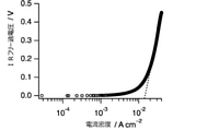
- the obtained Tafel plot is shown in FIG.
- the dotted line represents an approximate straight line obtained from the plot in the region where the IR free overvoltage is relatively high, and the value at IR free overvoltage 0 when this approximate straight line is extrapolated to the region where the IR free overvoltage is low.
- the exchange current density was obtained from.
- the obtained impedance spectrum is shown in FIG.
- the exchange current density of the hydrogen oxidation reaction by the nickel-rhodium complex obtained from the Tafel plot and the impedance measurement was 0.0286 mA cm -2 as shown in Table 6.
- Example 7-1 Electrode catalytic ability evaluation by turf plot and impedance measurement of a hydrogen-oxygen fuel cell using a nickel-rodium dry distillate catalyst as an anode electrode catalyst and platinum as a cathode electrode catalyst A configuration having a reversible hydrogen electrode as a reference electrode.
- a fuel cell was prepared in the same manner as in Example 4A-4, and hydrogen was used as the anode gas and oxygen was used as the cathode gas in the obtained fuel cell. Plots and impedance spectra were obtained.
- This Tafel plot and impedance measurement were performed using a nickel-rhodium carbonization catalyst (NiRh carbonization catalyst 600) as an anode, platinum as a cathode, and a reversible hydrogen electrode as a reference electrode.
- NiRh carbonization catalyst 600 nickel-rhodium carbonization catalyst 600
- platinum platinum as a cathode
- a reversible hydrogen electrode as a reference electrode.
- the obtained Tafel plot and impedance spectrum are shown in FIGS. 13 and 17, respectively.
- Example 8-1 Electrode catalytic ability evaluation by Tafel plot and impedance measurement of a hydrogen-oxygen fuel cell using a nickel-rodium dry distillate catalyst as a cathode electrode catalyst and platinum as an anode electrode catalyst A configuration having a reversible hydrogen electrode as a reference electrode.
- a fuel cell was prepared in the same manner as in Example 5A-4, and hydrogen was used as the anode gas and oxygen was used as the cathode gas in the obtained fuel cell. Plots and impedance spectra were obtained.
- This Tafel plot and impedance measurement were performed using platinum as the anode, a nickel-rhodium carbonization catalyst (NiRh carbonization catalyst 600) as the cathode, and a reversible hydrogen electrode as the reference electrode.
- NiRh carbonization catalyst 600 nickel-rhodium carbonization catalyst 600
- a reversible hydrogen electrode as the reference electrode.
- the obtained Tafel plot and impedance spectrum are shown in FIGS. 15 and 19, respectively.
- the exchange current density of the oxygen reduction reaction by the carbonization catalyst obtained from the Tafel plot and the impedance measurement was 10.5 mA cm -2 as shown in Table 6, which was 652 times higher than that of the nickel-rhodium complex.
Landscapes
- Chemical & Material Sciences (AREA)
- Chemical Kinetics & Catalysis (AREA)
- Engineering & Computer Science (AREA)
- General Chemical & Material Sciences (AREA)
- Materials Engineering (AREA)
- Electrochemistry (AREA)
- Organic Chemistry (AREA)
- Manufacturing & Machinery (AREA)
- Life Sciences & Earth Sciences (AREA)
- Physics & Mathematics (AREA)
- Thermal Sciences (AREA)
- Sustainable Development (AREA)
- Sustainable Energy (AREA)
- Inorganic Chemistry (AREA)
- Inert Electrodes (AREA)
- Catalysts (AREA)
- Fuel Cell (AREA)
Abstract
本発明は、燃料電池として用いたときに十分な性能を発揮することのできる電極触媒を提供することを目的とする。第1の遷移金属M1および第2の遷移金属M2を構成元素として含む触媒成分と導電性材料とを含む電極触媒であって、第1の遷移金属M1、第2の遷移金属M2、炭素、水素、窒素および硫黄を構成元素として含み、かつ、水素の含有量および窒素の含有量がともに1%未満である粒子であり、当該粒子の表面に第1の遷移金属M1の硫化物と第2の遷移金属M2が観測される電極触媒。
Description
本発明は、電極触媒およびその製造方法、並びに、これにより得られる燃料電池に関する。
従来、燃料電池用電極触媒としては、一般的にアノードとカソードいずれも白金触媒が幅広く利用されてきたが、白金触媒は高価かつ枯渇資源であることから、その代替触媒の開発が盛んに研究されてきた。
白金等の金属触媒の量を減少させるためには、単位金属あたりの触媒活性を最大限に引き出すことが考えられ、そのためには有機金属錯体を用いることが検討された(特許文献1)。また、硫黄を含む金属硫化物などは、アノードとカソード触媒の両方の優れた触媒として報告されている(特許文献2、非特許文献1及び2)。金属硫化物は、金属の種類や金属と硫黄の比率によりその触媒活性が変化する。そのような観点から、異なる2種類以上の金属と硫黄を含む触媒も、同様に幅広く研究されている(非特許文献3-5)。
また、無機金属塩及び有機金属錯体から選択される前駆体を焼成して得られた含窒素カーボンアロイが燃料電池用触媒として用いられることが知られている(特許文献3)。このようにして得られる一連のカーボンアロイについてはその構造が詳細に検討されている。例えば、非特許文献6には、鉄フタロシアニンとフェノール樹脂とからなる前駆体を焼成して得られるカーボンアロイ触媒(Carbon Alloy Catalyst、および、これについての放射光解析結果が示されている。
International J.of Hydrogen Energy,2017,42,14253-14263
J.Electrochem.Soc.,2015,162,F455-F462.
J.Appl.Electrochem,2016,46,497-503
J.Power.Source,2016,334,112-119
Electrochica Acta,2000,45,4237-4250
表面科学, Vol. 32, No. 11, pp. 716-722, 2011
有機金属錯体や金属硫化物を用いてなる従来の燃料電池用電極触媒は、依然として燃料電池として用いるには十分な性能を有しておらず、さらなる性能の向上が求められている。そこで、本発明は、燃料電池として用いたときに十分な性能を発揮することのできる電極触媒を提供することを目的とする。
本発明者らは、上記課題を検討した結果、2種類の異なる金属イオンが硫黄により架橋された金属錯体に乾留と呼ばれる熱処理の一種の技術を施すことにより、2種類の金属と硫黄が残存した不均一系触媒(乾留触媒)が生成することを見出した。さらに、その乾留触媒のうち、水素及び窒素の含有量が一定の範囲内にあるものが、当該乾留触媒を与える金属錯体と比べ触媒性能が大きく向上すること、該触媒が水素-酸素燃料電池のアノードとカソード両方の電極触媒として機能することを確認し、本発明を完成させた。
すなわち、本発明は以下の[1]~[17]に関する。
[1]
第1の遷移金属M1および第2の遷移金属M2を構成元素として含む触媒成分と導電性材料とを含む電極触媒であって、
第1の遷移金属M1、第2の遷移金属M2、炭素、水素、窒素および硫黄を構成元素として含み、かつ、水素の含有量および窒素の含有量がともに1重量%未満である粒子であり、
当該粒子の表面に第1の遷移金属M1の硫化物と第2の遷移金属M2が観測される電極触媒。
[2]
第1の遷移金属M1および第2の遷移金属M2を構成元素として含む触媒成分と導電性材料とを含む電極触媒であって、
第1の遷移金属M1、第2の遷移金属M2、炭素、水素、窒素および硫黄を構成元素として含み、かつ、水素の含有量および窒素の含有量がともに1重量%未満である粒子であり、
当該粒子の表面に第1の遷移金属の硫化物と金属態の第2の遷移金属が観測される電極触媒。
[3]
前記第1の遷移金属M1が、Ni、Mn、Fe、Co、Cu、およびZnからなる群より選ばれるいずれかであり、
前記第2の遷移金属M2が、Ru、Rh、Pd、Ag、Ir、およびPtからなる群より選ばれるいずれかである、前記[1]または[2]に記載の電極触媒。
前記第1の遷移金属M1が、Ni、Mn、Fe、Co、Cu、およびZnからなる群より選ばれるいずれかであり、
前記第2の遷移金属M2が、Ru、Rh、Pd、Ag、Ir、およびPtからなる群より選ばれるいずれかである、前記[1]または[2]に記載の電極触媒。
[4]
前記第1の遷移金属M1が、Niであり、
前記第2の遷移金属M2が、Ru、Rh、およびIrからなる群より選ばれるいずれかである、前記[1]または[2]に記載の電極触媒。
[5]
前記粒子の表面に、さらに第2の遷移金属M2の硫化物が観測される、前記[1]~[4]のいずれかに記載の電極触媒。
前記第1の遷移金属M1が、Niであり、
前記第2の遷移金属M2が、Ru、Rh、およびIrからなる群より選ばれるいずれかである、前記[1]または[2]に記載の電極触媒。
[5]
前記粒子の表面に、さらに第2の遷移金属M2の硫化物が観測される、前記[1]~[4]のいずれかに記載の電極触媒。
[6]
前記導電性材料が、アセチレンブラック、バルカン、ケッチェンブラック、ブラックパール、黒鉛化アセチレンブラック、黒鉛化バルカン、黒鉛化ケッチェンブラック、黒鉛化ブラックパール、カーボンナノチューブ、カーボンナノファイバー、カーボンナノホーン、およびカーボンフィブリルからなる群より選ばれるいずれかである、前記[1]~[5]のいずれかに記載の電極触媒。
前記導電性材料が、アセチレンブラック、バルカン、ケッチェンブラック、ブラックパール、黒鉛化アセチレンブラック、黒鉛化バルカン、黒鉛化ケッチェンブラック、黒鉛化ブラックパール、カーボンナノチューブ、カーボンナノファイバー、カーボンナノホーン、およびカーボンフィブリルからなる群より選ばれるいずれかである、前記[1]~[5]のいずれかに記載の電極触媒。
[7]
下記工程1aおよび2aを含む、電極触媒の製造方法:
工程1a:下記式(1)
下記工程1aおよび2aを含む、電極触媒の製造方法:
工程1a:下記式(1)

工程2a:前記工程1aで得られた混合物を乾留させる工程。
[8]
前記工程2aが、真空下かつ100~800℃の温度で行われる、前記[7]に記載の製造方法。
前記工程2aが、真空下かつ100~800℃の温度で行われる、前記[7]に記載の製造方法。
[9]
前記温度が300~800℃の範囲内である、前記[8]に記載の製造方法。
[10]
前記真空が、真空度10~20Paである、前記[8]または[9]に記載の製造方法。
前記温度が300~800℃の範囲内である、前記[8]に記載の製造方法。
[10]
前記真空が、真空度10~20Paである、前記[8]または[9]に記載の製造方法。
[11]
前記導電性材料が、アセチレンブラック、バルカン、ケッチェンブラック、ブラックパール、黒鉛化アセチレンブラック、黒鉛化バルカン、黒鉛化ケッチェンブラック、黒鉛化ブラックパール、カーボンナノチューブ、カーボンナノファイバー、カーボンナノホーン、およびカーボンフィブリルからなる群より選ばれるいずれかである、前記[7]~[10]のいずれかに記載の製造方法。
前記導電性材料が、アセチレンブラック、バルカン、ケッチェンブラック、ブラックパール、黒鉛化アセチレンブラック、黒鉛化バルカン、黒鉛化ケッチェンブラック、黒鉛化ブラックパール、カーボンナノチューブ、カーボンナノファイバー、カーボンナノホーン、およびカーボンフィブリルからなる群より選ばれるいずれかである、前記[7]~[10]のいずれかに記載の製造方法。
[12]
前記[10]に記載の製造方法で得られた電極触媒。
[13]
前記[1]~[6],[12]のいずれかに記載の電極触媒を含む燃料電池用電極。
前記[10]に記載の製造方法で得られた電極触媒。
[13]
前記[1]~[6],[12]のいずれかに記載の電極触媒を含む燃料電池用電極。
[14]
カソードと、アノードと、前記カソードと前記アノードとの間に配置されたプロトン伝導膜とを有する膜電極接合体であって、カソードとアノードとからなる群より選ばれるいずれか1以上が前記[13]に記載の燃料電池用電極である膜電極接合体。
カソードと、アノードと、前記カソードと前記アノードとの間に配置されたプロトン伝導膜とを有する膜電極接合体であって、カソードとアノードとからなる群より選ばれるいずれか1以上が前記[13]に記載の燃料電池用電極である膜電極接合体。
[15]
前記[14]に記載の膜電極接合体を備えることを特徴とする燃料電池。
[16]
前記[13]に記載の燃料電池用電極を、カソード、アノード、または、カソードとアノードとの両方として有する燃料電池。
前記[14]に記載の膜電極接合体を備えることを特徴とする燃料電池。
[16]
前記[13]に記載の燃料電池用電極を、カソード、アノード、または、カソードとアノードとの両方として有する燃料電池。
[17]
水素-酸素型燃料電池である前記[15]または[16]に記載の燃料電池。
水素-酸素型燃料電池である前記[15]または[16]に記載の燃料電池。
本発明によれば、燃料電池として用いたときに十分な性能を発揮することができ、且つ、アノードとカソードの両方に用いることができる電極触媒を提供することができる。また、本発明の触媒を用いることで、水素と酸素を用いた触媒反応を広範囲に制御できる。
〔電極触媒〕
本発明に係る電極触媒は、
第1の遷移金属M1および第2の遷移金属M2を構成元素として含む触媒成分と導電性材料とを含む電極触媒であって、
第1の遷移金属M1、第2の遷移金属M2、炭素、水素、窒素および硫黄を構成元素として含む粒子である。
本発明に係る電極触媒は、
第1の遷移金属M1および第2の遷移金属M2を構成元素として含む触媒成分と導電性材料とを含む電極触媒であって、
第1の遷移金属M1、第2の遷移金属M2、炭素、水素、窒素および硫黄を構成元素として含む粒子である。
本発明の好適な態様において、前記第1の遷移金属M1は、Ni、Mn、Fe、Co、Cu、およびZnからなる群より選ばれるいずれかである。ここで、本発明の特に好適な態様において、前記第1の遷移金属M1は、Niである。
一方、前記第2の遷移金属M2は、通常、前記第1の遷移金属M1とは異なる遷移金属であり、本発明の好適な態様において、Ru、Rh、Pd、Ag、Ir、およびPtからなる群より選ばれるいずれかである。ここで、本発明の特に好適な態様において、前記第2の遷移金属M2は、Ru、Rh、およびIrからなる群より選ばれるいずれかである。
本発明においては、前記粒子における水素の含有量および窒素の含有量がともに1重量%未満である。これは、第1の遷移金属M1、第2の遷移金属M2、炭素、水素、窒素および硫黄を構成元素として含む粒子であっても、水素の含有量および窒素の含有量がともに1重量%未満である粒子では、燃料電池用の電極触媒として用いたときに、それ以外の粒子と比べて顕著に高い電力密度が得られたという本発明者らの知見に基づいている。ここで、前記水素の含有量は、より高い電力密度が得られる点から、0.90重量%以下であることが好ましく、0.50重量%以下であることがより好ましく、0.30重量%以下であることが特に好ましい。前記水素の含有量の下限値については、本願発明の効果が発揮できる限り特に限定はないものの、0.01重量%以上であることが好ましく、0.10重量%以上であることがより好ましい。一方、前記窒素の含有量は、より高い電力密度が得られる点から、0.30重量%以下であることが好ましく、0.25重量%以下であることがより好ましく、0.22重量%以下であることが特に好ましい。前記窒素の含有量の下限値については、本願発明の効果が発揮できる限り特に限定はないものの、0.01重量%以上であることが好ましく、0.10重量%以上であることがより好ましい。
また、本発明において前記粒子は、水素及び窒素の含有量は少ないが硫黄の含有量は比較的多い傾向にある。本発明では、前記硫黄の含有量は、前記水素及び窒素の含有量と比べて大幅に多いと高い電力密度が得られる傾向にあり、例えば、前記水素の含有量の5倍以上、好ましくは10倍以上、より好ましくは15倍以上である。また、前記硫黄の含有量は、前記窒素の含有量の10倍以上、好ましくは20倍以上である。前記硫黄の含有量の具体的な数値については、本願発明の効果が発揮できる限り特に限定はない。ただ、具体的な下限値については、2重量%以上であることが好ましく、3重量%以上であることがより好ましい。一方、具体的な上限値については、特に限定はないものの、多くの場合10重量%以下、例えば8重量%以下である。ここで、本発明の好適且つ例示的な態様において、前記硫黄の含有量は3~6重量%であるが、これに限定されるものではない。
なお、前記粒子を構成する各元素の含有量は、元素分析によって求めることができる。
また、前記粒子の表面には、第1の遷移金属M1の硫化物と第2の遷移金属M2が観測される。このことは、後述する実施例においても確認されている(例えば、下記「実施例」中「III.乾留触媒の同定」の記載を参照のこと。)。ここで、本発明の好適な態様の1つにおいて、前記粒子の表面には、第1の遷移金属M1の硫化物と金属態の第2の遷移金属M2が観測される。また、本発明のもう1つの好適な態様において、前記粒子の表面には、さらに第2の遷移金属M2の硫化物が観測される。本発明の例示的且つ好適な態様の1つにおいて、前記粒子の表面には、第1の遷移金属M1の硫化物、金属態の第2の遷移金属M2及び第2の遷移金属M2の硫化物が観測される。ここで、「金属態」とは、対象とする金属の価数が0価であることを意味する。第1の遷移金属M1の硫化物の存在は、XRDとXPSによって確認することができる。また、金属態の前記第2の遷移金属M2の存在は、XRDとXPSによって確認することができる。また、第2の遷移金属M2の硫化物の存在は、XRDによって確認することができる。
このような電極触媒は、第1の遷移金属M1、第2の遷移金属M2、炭素、水素、窒素および硫黄を構成元素として含む触媒成分と、導電性材料とを含む複合触媒と見ることもできる。本発明の好適な態様の1つにおいて、前記触媒成分は、水素および窒素を構成原子として含む有機配位子を有する第1の遷移金属M1と、第2の遷移金属M2と、当該第1の遷移金属M1と当該第2の遷移金属M2とをリンクする硫黄原子とを含む有機金属錯体を乾留してなる熱処理物である。
一方、本発明の電極触媒は、導電性材料をも含む。本発明の電極触媒を構成する導電性材料の例としては、アセチレンブラック、バルカン、ケッチェンブラック、ブラックパール、黒鉛化アセチレンブラック、黒鉛化バルカン、黒鉛化ケッチェンブラック、黒鉛化ブラックパール、カーボンナノチューブ、カーボンナノファイバー、カーボンナノホーン、およびカーボンフィブリルが挙げられる。本発明で用いられる導電性材料は、1種単独であっても良く、2種以上の組み合わせであっても良い。
本発明の電極触媒における前記導電性材料の含量は、本発明の効果が得られる限りにおいて特に限定されないものの、電極触媒の全体量に対して通常1重量%以上99重量%以下である。ただ、本発明の電極触媒を後述する製造方法Aによって得る場合、得られる電極触媒における前記導電性材料の含量は、後述する工程1で得られる混合物における前記導電性材料の含量よりも多くなると考えられる、例えば、工程1において前記導電性材料と下記式(A)で表される金属錯体とを同量用いた場合、得られる電極触媒における前記導電性材料の量は、当該金属錯体から得られる第1の遷移金属M1および第2の遷移金属M2を構成元素として含む触媒成分の量より多いと見込まれる。このことから、本発明の好適且つ例示的な態様の1つにおいて、本発明の電極触媒における前記導電性材料の含量の下限値は、好ましくは30重量%以上、より好ましくは50重量%以上であり、上限値は、好ましくは80重量%以下、より好ましくは70重量%以下である。
〔電極触媒の製造方法〕
本発明に係る電極触媒は、例えば、
水素および窒素を構成原子として含む有機配位子を有する第1の遷移金属M1と、第2の遷移金属M2と、当該第1の遷移金属M1と当該第2の遷移金属M2とをリンクする硫黄原子とを含む有機金属錯体を導電性材料と混合し、混合物を得る工程と、
前記混合物を乾留させる工程と
を含む製造方法によって得ることができる。
本発明に係る電極触媒は、例えば、
水素および窒素を構成原子として含む有機配位子を有する第1の遷移金属M1と、第2の遷移金属M2と、当該第1の遷移金属M1と当該第2の遷移金属M2とをリンクする硫黄原子とを含む有機金属錯体を導電性材料と混合し、混合物を得る工程と、
前記混合物を乾留させる工程と
を含む製造方法によって得ることができる。
ここで、前記硫黄原子は、前記有機配位子に含まれていることが好ましい。すなわち、前記有機配位子は、水素、窒素および硫黄を構成原子として含み、且つ、当該有機配位子を構成する硫黄が、前記第1の遷移金属M1と前記第2の遷移金属M2とをリンクしていることが好ましい。このような有機配位子を構成する分子の例として、ω-メルカプトアルキル基を2以上有するアミン、ω-メルカプトアルキル基を2以上有するアルキレンジアミン、ω-メルカプトアルキル基を2以上有するポリアルキレンイミンなどが挙げられる。前記アミン、前記アルキレンジアミンおよび前記ポリアルキレンイミンを構成する窒素原子は、それぞれ独立に、メチル基などのアルキル基と結合していることが好ましい。本発明の好適な態様において、前記ω-メルカプトアルキル基を2以上有するポリアルキレンイミンは、両端の窒素原子にω-メルカプトアルキル基が1つずつ結合してなる直鎖状のポリアルキレンイミンであり、その例として、N,N'-ジメチル-3,7-ジアザノナン-1,9-ジチオールが挙げられる。
また、有機金属錯体を構成する第1の遷移金属M1および当該第2の遷移金属M2は、前記「電極触媒」の項で上述したものと同様である。
前記製造方法を用いる場合、有機金属錯体を構成する金属種や配位子を変えることにより、得られる電極触媒の触媒能力を制御することが容易である傾向にある。例えば、第1の遷移金属M1と第2の遷移金属M2との組み合わせを変更することにより、得られる電極触媒の触媒能力を変えることが可能である。
前記製造方法を用いる場合、有機金属錯体を構成する金属種や配位子を変えることにより、得られる電極触媒の触媒能力を制御することが容易である傾向にある。例えば、第1の遷移金属M1と第2の遷移金属M2との組み合わせを変更することにより、得られる電極触媒の触媒能力を変えることが可能である。
ここで、本発明の好適且つ例示的な態様において、前記製造方法は、下記工程1および2を含む製造方法Aである:
工程1:下記式(A)

(式(A)において、M1は、前記第1の遷移金属M1であり、M2は前記第2の遷移金属M2である。L、XおよびYは、適当な配位子を表し、Xは、M1とブリッジを形成していても良い。l、mおよびnは、それぞれ独立して2~4の整数である。Rはそれぞれ独立して、炭素数1~5のアルキル基である。zは錯体の電荷を表し、0または2+である。)で表される金属錯体を導電性材料と混合し、混合物を得る工程;並びに、
工程2:前記工程1で得られた混合物を乾留させる工程。
工程1:下記式(A)
工程2:前記工程1で得られた混合物を乾留させる工程。
ここで、本発明の典型的且つ好適な態様の1つにおいて、前記製造方法Aは、下記工程1aおよび2aを含む製造方法A1である:
工程1a:下記式(1)
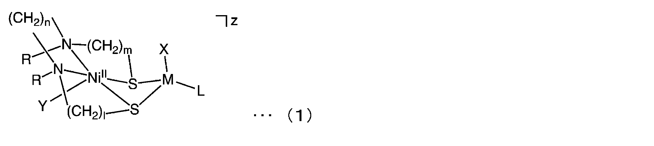
(式(1)において、Mは、RuII、RhIIIまたはIrIIIである。Lはヘキサメチルベンゼン基またはペンタメチルシクロペンタジエニル基を表す。Xは、ハロゲン原子または水素原子、ヒドリドイオンを表し、Xが水素原子、ヒドリドイオンの場合、XはNiIIとブリッジを形成していても良い。Yは、ハロゲン原子またはH2Oを表す。l、mおよびnは、それぞれ独立して2~4の整数である。Rはそれぞれ独立して、炭素数1~5のアルキル基である。zは錯体の電荷を表し、0または2+である。)で表される金属錯体を導電性材料と混合し、混合物を得る工程;並びに、
工程2a:前記工程1aで得られた混合物を乾留させる工程。
工程1a:下記式(1)
工程2a:前記工程1aで得られた混合物を乾留させる工程。
ここで、本発明の特に好適な態様において、上記(1)の金属錯体は、Ni原子に配位する有機配位子として、N,N'-ジメチル-3,7-ジアザノナン-1,9-ジチオラート配位子(前記lおよびnが2であり、前記mが3であり、Rがメチル基である場合に相当する。本明細書において、「N2S2」と称する場合がある。)を、前記Lとして、ペンタメチルシクロペンタジエニル基を、それぞれ有している。
また、前記XおよびYを構成しうるハロゲン原子は、好ましくは塩素原子である。
また、前記Mは、好ましくはRhIIIである。
上記(1)の金属錯体は、従来公知の方法を用いて得ることができ、例えば、Inorg.Chem.,1990,4779-4788、Inorg.Chem.1990,29,2023-2025、Org.Lett.2004,6,2785-2788、Science 2007,316,585-587、Angew. Chem. Int. Ed. 2013,56,9723-9726、および、特開2017-132671号公報等に記載されている方法を参照して得ることができる。
また、前記Mは、好ましくはRhIIIである。
上記(1)の金属錯体は、従来公知の方法を用いて得ることができ、例えば、Inorg.Chem.,1990,4779-4788、Inorg.Chem.1990,29,2023-2025、Org.Lett.2004,6,2785-2788、Science 2007,316,585-587、Angew. Chem. Int. Ed. 2013,56,9723-9726、および、特開2017-132671号公報等に記載されている方法を参照して得ることができる。
前記混合物を得る工程は、前記製造方法Aにおける工程1および前記製造方法A1における工程1aも含めて、従来公知の方法により行うことができる。ここで、上記式(A)または上記式(1)で表される金属錯体とともに配合され前記混合物に含まれることになる導電性材料は、上記「電極触媒」の項で上述した導電性材料と同様である。
一方、前記混合物を乾留させる工程は、前記製造方法Aにおける工程2および前記製造方法A1における工程2aも含め、混合物を熱処理する工程として行われる。この乾留により、混合物に含まれている有機金属錯体の熱分解が起こり、水素を構成元素として含む揮発性成分や窒素を構成元素として含む揮発性成分が脱離する。例えば、上記式(1)で表される金属錯体の場合、このような熱分解は、220℃付近から始まる場合がある。一方、有機金属錯体に由来する含硫黄成分は、水素を構成元素として含む揮発性成分や窒素を構成元素として含む揮発性成分が脱離する温度条件下においても、比較的脱離しにくい傾向にある。その結果として、第1の遷移金属M1と第2の遷移金属M2を構成元素として含む化学種として、水素及び窒素の含有量は少ないが硫黄の含有量は比較的多い何らかの化学種が生成し、これが乾留触媒として機能するものと推測している。
ここで、前記乾留は、通常、真空下、または、窒素やアルゴン等の雰囲気下で行うことができ、分解生成物除去の観点から真空下で行うことが好ましい。ここで、前記真空の程度は、通常、真空度10~20Paである。
前記乾留を行う温度は、当該乾留によって得られる触媒(以下「乾留触媒」)が本発明の効果を奏しうる限り特に限定されない。ただ、前記乾留を行う温度が高いほど、得られる乾留触媒における水素の含有量および窒素の含有量が少なくなる傾向にある。下記で後述する実施例で確認されたように、水素の含有量および窒素の含有量がある程度少ない乾留触媒は、燃料電池用の電極触媒として用いたときに高い電力密度を得ることができ、有利である。これらを踏まえると、前記乾留を行う温度は、通常100~800℃である。前記乾留を行う温度は、好ましくは200℃以上、より好ましくは300℃以上、さらに好ましくは600℃以上である。一方、前記乾留を行う温度の上限については、通常800℃以下、好ましくは700℃以下である。
例えば、前記製造方法A1における工程2aでは、前記乾留を行う温度は、典型的には300~800℃であり、好ましくは400~800℃である。このような温度で乾留を行うことにより、上記「電極触媒」の項で上述した要件を満たす電極触媒を得ることができる。
上記製造方法によって得られた乾留触媒は、電極触媒として用いることができる。
上記製造方法によって得られた乾留触媒は、電極触媒として用いることができる。
〔電極〕
上述した本発明に係る電極触媒は、燃料電池用電極に用いることができる。すなわち、本発明に係る燃料電池用電極は、上記電極触媒を含むことになる。
上述した本発明に係る電極触媒は、燃料電池用電極に用いることができる。すなわち、本発明に係る燃料電池用電極は、上記電極触媒を含むことになる。
ここで、本発明に係る燃料電池用電極は、一定の形状を保持できる限り上記電極触媒のみからなることを妨げないものの、必要に応じて上記電極触媒以外の成分(以下、「他の成分」)を含有していてもよい。このような「他の成分」の例として、バルカン(Cabot社製)、カーボンブラック、アセチレンブラック、ファーネスブラック、グラファイト、カーボンナノチューブ、カーボンナノファイバー、黒煙、炭素繊維および活性炭等の触媒担持体;ポリアセチレン、ポリピロール、ポリチオール、ポリイミダゾール、ポリピリジン、ポリアニリンおよびポリチオフェン等の導電性高分子を挙げることができる。上記電極触媒の量を100重量部としたときの「他の成分」の量は、触媒担持体にあっては好ましくは0重量部以上50重量部以下であり、上記導電性高分子にあっては好ましくは0重量部以上50重量部以下である。
また、本発明に係る燃料電池用電極は、ガス拡散性を有する導電性材料からなる層(以下「ガス拡散層」)と、上記電極触媒からなる層(以下「触媒層」)とを有する積層体であってもよい。このガス拡散層は、上記触媒層を支持する役割も有している。ガス拡散層としては、電子伝導性を有し、ガスの拡散性が高く、耐食性の高いものであれば何であっても構わないが、一般的にはカーボンペーパー、カーボンクロスなどの炭素系多孔質材料が用いられる。このような燃料電池用電極は、例えば、上記電極触媒に適当な媒体を加えて、溶液、懸濁液、スラリー、ペースト等とし、これを上記ガス拡散層に塗布し、乾燥させることにより形成される。ここで、上記電極触媒を、溶液、懸濁液、スラリー、ペースト等とするための媒体も特に限定されるものではなく、従来公知の媒体から適宜選択して用いればよい。塗布量は0.1~10mg/cm2とすることが好ましく、より好ましくは0.5~5mg/cm2である。
一方、上記触媒層は、上記電極触媒に加え、必要に応じて、上記触媒担持体、導電性高分子またはアイオノマー等を含有していてもよい。上記触媒担持体、導電性高分子またはアイオノマー等は、上記電極触媒の溶液、懸濁液、スラリーまたはペースト等に添加してもよいし、上記電極触媒の溶液、懸濁液、スラリーまたはペースト等とは別に、溶液、懸濁液、溶液、スラリーまたはペースト等として、触媒層を塗布する前、同時、又は後に塗布してもよい。
燃料電池において、アノード(負極または燃料極ともいう)では燃料の酸化反応が起こり、カソード(正極または空気極ともいう)では酸化剤の還元が起こる。本発明に係る燃料電池用電極は、アノードであっても良く、カソードであっても良い。また、アノードおよびカソードの両方であっても良い。本発明の特に好適な態様において、前記燃料電池用電極は、カソードである。
〔膜電極接合体〕
本発明に係る膜電極接合体は、カソードと、アノードと、前記カソードと前記アノードとの間に配置されたプロトン伝導膜とを有する膜電極接合体であって、カソードとアノードとからなる群より選ばれるいずれか1以上が上述した本発明の燃料電池用電極である。
このとき、本発明の燃料電池用電極を採用しなかった方の電極として、従来公知の燃料電池用電極、例えば、白金担持カーボンなど白金系触媒を含む燃料電池用電極を用いることができる。本発明の膜電極接合体の特に好適な態様の一例として、カソードが本発明の燃料電池用電極であり、アノードが従来公知の燃料電池用電極であるものが挙げられる。
本発明に係る膜電極接合体は、カソードと、アノードと、前記カソードと前記アノードとの間に配置されたプロトン伝導膜とを有する膜電極接合体であって、カソードとアノードとからなる群より選ばれるいずれか1以上が上述した本発明の燃料電池用電極である。
このとき、本発明の燃料電池用電極を採用しなかった方の電極として、従来公知の燃料電池用電極、例えば、白金担持カーボンなど白金系触媒を含む燃料電池用電極を用いることができる。本発明の膜電極接合体の特に好適な態様の一例として、カソードが本発明の燃料電池用電極であり、アノードが従来公知の燃料電池用電極であるものが挙げられる。
ここで、本発明の燃料電池用電極がガス拡散層を有する場合、本発明の膜電極接合体においてこのガス拡散層は、プロトン伝導膜から見て、上記電極触媒からなる層の反対側に配置される。
プロトン伝導膜としては、例えば、パーフルオロスルホン酸系を用いた電解質膜または炭化水素系電解質膜などが一般的に用いられる。プロトン伝導膜の具体例としては、ナフィオン(登録商標)、フレミオン(登録商標)、アシプレックス(登録商標)等のプロトン伝導性高分子電解質が挙げられる。
本発明の膜電極接合体は、従来公知の方法を用いて適宜形成することができる。
本発明の膜電極接合体は、従来公知の方法を用いて適宜形成することができる。
〔燃料電池〕
本発明の燃料電池は、上述した本発明の膜電極接合体を備える。ここで、本発明の典型的な態様において、本発明の燃料電池は、膜電極接合体を挟む態様でさらに2つの集電体を備える。
本発明の燃料電池は、上述した本発明の膜電極接合体を備える。ここで、本発明の典型的な態様において、本発明の燃料電池は、膜電極接合体を挟む態様でさらに2つの集電体を備える。
本発明の燃料電池は、上述した本発明の燃料電池用電極を、カソード、アノード、または、カソードとアノードとの両方として有している。ここで、本発明の特に好適な態様において、前記燃料電池用電極は、カソードである。本発明の燃料電池用電極をカソードとして有し、従来公知の燃料電池用電極をアノードとして有する燃料電池は、高い電力密度が得られる点で特に好ましい。一方、高価な白金単体や白金合金の使用を減らすことができ、かつ、触媒能力の制御をより容易に行うことができるという観点からは、燃料電池が、上述した本発明の燃料電池用電極をカソードとアノードとの両方として有することが好ましい。
また、前記集電体は、燃料電池用に一般的に採用される従来公知のものとすることができ、例えば、図6に図示したように、流路を内蔵した集電板の形状とすることができる。
燃料電池の外部から導入されるアノードガスは、アノード側に配された集電体を通じてアノードに供給され、燃料電池の外部から導入されるカソードガスは、カソード側に配された集電体を通じてカソードに供給される。前記アノードガスは、燃料となるガスであり、典型的には、水素である。ここでアノードガスが水素の場合、この水素は、ガソリン、メタノール、ジエチルエーテルまたは炭化水素等を改質して得られるものであっても良い。また、前記カソードガスは、メタノールまたはジエチルエーテル等であっても良い。
燃料電池の外部から導入されるアノードガスは、アノード側に配された集電体を通じてアノードに供給され、燃料電池の外部から導入されるカソードガスは、カソード側に配された集電体を通じてカソードに供給される。前記アノードガスは、燃料となるガスであり、典型的には、水素である。ここでアノードガスが水素の場合、この水素は、ガソリン、メタノール、ジエチルエーテルまたは炭化水素等を改質して得られるものであっても良い。また、前記カソードガスは、メタノールまたはジエチルエーテル等であっても良い。
一方、燃料電池の外部から導入されるカソードガスは、酸化剤となるガスであり、酸素であっても良く、空気であっても良い。
本発明の好適な態様において、前記アノードガスは水素であり、前記カソードガスは酸素である。この態様では、本発明の燃料電池は、水素-酸素型燃料電池として用いられることになる。
本発明の好適な態様において、前記アノードガスは水素であり、前記カソードガスは酸素である。この態様では、本発明の燃料電池は、水素-酸素型燃料電池として用いられることになる。
〔発電方法〕
上述した本発明に係る電極触媒および燃料電池に関連して、本発明は、発電方法も提供するといえる。これは、本発明の電極触媒は、安価であり、且つ、燃料電池用電極として用いたときに触媒能力の制御が容易にできることに基づく。
上述した本発明に係る電極触媒および燃料電池に関連して、本発明は、発電方法も提供するといえる。これは、本発明の電極触媒は、安価であり、且つ、燃料電池用電極として用いたときに触媒能力の制御が容易にできることに基づく。
本発明に係る発電方法は、上記電極触媒を用いて、燃料の酸化反応を行う工程、および/または、上記電極触媒を用いて、酸化剤の還元反応を行う工程を含む。すなわち、本発明に係る発電方法は、上記電極触媒を用いて燃料の酸化反応を行う工程と、上記電極触媒を用いて酸化剤の還元反応を行う工程とのうちの両方を含んでいてもよいし、あるいは、いずれか一方を含んでいてもよい。
より具体的には、例えば、本発明に係る発電方法は、上記燃料電池用電極触媒を用いて水素分子から電子を放出させて水素イオンとする工程、および/または、上記燃料電池用電極触媒を用いて、酸素分子、水素イオンおよび電子を反応させて水を生成する工程を含む。
本発明に係る発電方法は、従来公知の方法により行えばよく、特に限定されるものではないが、一例を説明すると、燃料電池のアノード側に水素ガスを、カソード側に酸素を供給する。このとき水素ガスおよび酸素はバブラーを通して加湿してもよい。
アノード側から水素ガスが供給されると、水素ガスが上記燃料電池用電極触媒の作用によって水素分子から電子を放出して水素イオンとなる。この水素イオンは電解質膜を通過して対向するカソードに移動する。カソードでは、上記燃料電池用電極触媒の作用により、移動してきた水素イオンと、カソードに供給される酸素分子とが反応して水を生成する。このとき、電線に生じる電子の流れが直流電流として取り出される。
以下に本発明の実施例について具体的に説明するが、本発明はこれらに限定されない。
(材料および方法)
全ての実験は、標準のシュレンク技術及びグローブボックスを用いることによってN2又はAr雰囲気下で実施した。
(材料および方法)
全ての実験は、標準のシュレンク技術及びグローブボックスを用いることによってN2又はAr雰囲気下で実施した。
・各種金属錯体の調製
NiII(N2S2)は、文献(Inorg.Chem.,1990,4779-4788)に記載の方法によりNiII(N2S2)において記述されている方法によって調製した(N2S2=N,N'-dimethyl-3,7-diazanonane-1,9-dithiolato)。
NiII(N2S2)は、文献(Inorg.Chem.,1990,4779-4788)に記載の方法によりNiII(N2S2)において記述されている方法によって調製した(N2S2=N,N'-dimethyl-3,7-diazanonane-1,9-dithiolato)。
[IrIII(η5-C5Me5)Cl2]2は、文献(Inorg.Chem.1990,29,2023-2025)に記載の方法により[IrIII(η5-C5Me5)Cl2]2において記述されている方法によって調製した(η5-C5Me5=1,2,3,4,5-pentamethylcyclopentadienyl)。
[RhIII(η5-C5Me5)Cl2]2は、文献(Org.Lett.2004,6,2785-2788)に記載の方法により[IrIII(η5-C5Me5)Cl2]2において記述されている方法によって調製した。
[NiII(H2O)(N2S2)(μ-H)RuII(η6-C6Me6)](NO3)は、文献(Science 2007,316,585-587)に記載の方法により調製した。
[NiIICl(N2S2)IrIIICl(η5-C5Me5)]は、文献(Angew. Chem. Int. Ed. 2013,56,9723-9726)に記載の方法において記述されている方法によって調製した。
[NiIICl(N2S2)RhIIICl(η5-C5Me5)]は、文献(特開2017-132671号公報)において記述されている方法によって調製した。
・ガス及び溶媒
H2ガス、O2ガスは、太陽東洋酸素株式会社から購入した。H2O は、和光純薬工業株式会社から購入した。
これらは、更に精製することなしに使用した。
H2ガス、O2ガスは、太陽東洋酸素株式会社から購入した。H2O は、和光純薬工業株式会社から購入した。
これらは、更に精製することなしに使用した。
・紫外線可視スペクトル
紫外線可視スペクトルは、25℃にて日本分光V-670 UV-Visible-NIR分光計(セルの長さ0.1 cm)で測定した。
紫外線可視スペクトルは、25℃にて日本分光V-670 UV-Visible-NIR分光計(セルの長さ0.1 cm)で測定した。
・ガスクロマトグラフィー-質量分析法(GC-MS)
ガスクロマトグラフィー-質量分析法(GC-MS)データは、SHIMADZU GCMS-QP 2010によって得た。
ガスクロマトグラフィー-質量分析法(GC-MS)データは、SHIMADZU GCMS-QP 2010によって得た。
・示差熱-熱重量同時測定(TG-DSC)
示差熱-熱重量同時測定(TG-DSC)データは、NETZCCH STA 449 F1 Jupiter分析器によって得た。
示差熱-熱重量同時測定(TG-DSC)データは、NETZCCH STA 449 F1 Jupiter分析器によって得た。
・X線光電子分光(XPS)
X線光電子分光(XPS)スペクトルは、AlアノードX線源を備え付けたULVAC PHI 5000 VersaProbe II systemによって得た。結合エネルギーは、サンプルと混合した金粉中の金元素のAu 4f7/2のピークで補正した。
X線光電子分光(XPS)スペクトルは、AlアノードX線源を備え付けたULVAC PHI 5000 VersaProbe II systemによって得た。結合エネルギーは、サンプルと混合した金粉中の金元素のAu 4f7/2のピークで補正した。
・X線回折(XRD)法
X線回折(XRD)パターンは、45 kV及び200 mAで放出されるCu-Kα放射を備え付けたRigaku SmartLab {スキャン速度 0.02o min-1 (2θ = 20-90o)によって得た。
X線回折(XRD)パターンは、45 kV及び200 mAで放出されるCu-Kα放射を備え付けたRigaku SmartLab {スキャン速度 0.02o min-1 (2θ = 20-90o)によって得た。
・元素分析データ
元素分析データは、Yanaco CHN-coder MT-5及びパーキンエルマー2400 II シリーズCHNS/O 分析器によって得た。
元素分析データは、Yanaco CHN-coder MT-5及びパーキンエルマー2400 II シリーズCHNS/O 分析器によって得た。
・(走査型)透過電子顕微鏡((S)TEM)観察、及びエネルギー分散型X線分光法(EDS)マッピング
(走査型)透過電子顕微鏡((S)TEM)観察、及びエネルギー分散型X線分光法(EDS)マッピングデータは、JEOL JEM-ARM 200F equipped with a JEOL silicon drift detector (SDD) and a JEOL JED-2300T systemによって得た。
(走査型)透過電子顕微鏡((S)TEM)観察、及びエネルギー分散型X線分光法(EDS)マッピングデータは、JEOL JEM-ARM 200F equipped with a JEOL silicon drift detector (SDD) and a JEOL JED-2300T systemによって得た。
I.乾留触媒の合成
[実施例1-1]ニッケル・ロジウムクロロ錯体[NiIICl(N2S2)RhIIICl(η5-C5Me5)]を用いたニッケル・ロジウム乾留触媒の合成
ニッケル・ロジウムクロロ錯体[NiIICl(N2S2)RhIIICl(η5-C5Me5)](以下「ニッケル・ロジウムクロロ錯体」または「NiRh錯体」と呼ばれる場合がある。)(5mg) をカーボンブラック(5mg) と混合し、電気炉を取り付けた石英菅(以下「装置」)内に導入した。真空ポンプにより装置内を約20Paまで減圧した。その後サンプルを減圧下(15-20 Pa)にて1時間加熱した。加熱は、室温からの昇温で開始し、目標とする温度(以下「乾留温度」)に到達した後(室温から乾留温度に到るまでの所要時間はほぼ5分以内)、この温度で1時間保持することによって行った。加熱後、装置内の減圧を解いてからサンプルを装置から取り出し、装置外の大気中で当該サンプルを室温まで冷却し、サンプルを装置から取り出した。得られたサンプルは、以下の実施例において、ニッケル・ロジウム乾留触媒として用いた。
乾留温度を100-800℃の範囲内で変えながら、同様の合成を繰り返した。
[実施例1-2]ニッケル・イリジウムクロロ錯体[NiIICl(N2S2)IrIIICl(η5-C5Me5)]を用いたニッケル・イリジウム乾留触媒の合成
ニッケル・ロジウムクロロ錯体の代わりにニッケル・イリジウムクロロ錯体[NiIICl(N2S2)IrIIICl(η5-C5Me5)](以下「ニッケル・イリジウムクロロ錯体」または「NiIr錯体」と呼ばれる場合がある。)を用いたことを除き、実施例1-1と同様の乾留触媒合成実験を行なった。
ニッケル・ロジウムクロロ錯体の代わりにニッケル・イリジウムクロロ錯体[NiIICl(N2S2)IrIIICl(η5-C5Me5)](以下「ニッケル・イリジウムクロロ錯体」または「NiIr錯体」と呼ばれる場合がある。)を用いたことを除き、実施例1-1と同様の乾留触媒合成実験を行なった。
[実施例1-3]ニッケル・ルテニウムヒドリド錯体[NiII(H2O)(N2S2)(μ-H)RuII(η6-C6Me6)](NO3)を用いたニッケル・ルテニウム乾留触媒の合成
ニッケル・ロジウムクロロ錯体の代わりにニッケル・ルテニウムヒドリド錯体[NiII(H2O)(N2S2)(μ-H)RuII(η6-C6Me6)](NO3)(以下「ニッケル・ルテニウムヒドリド錯体」または「NiRu錯体」と呼ばれる場合がある。)を用いたことを除き、実施例1-1と同様の乾留触媒合成実験を行なった。
ニッケル・ロジウムクロロ錯体の代わりにニッケル・ルテニウムヒドリド錯体[NiII(H2O)(N2S2)(μ-H)RuII(η6-C6Me6)](NO3)(以下「ニッケル・ルテニウムヒドリド錯体」または「NiRu錯体」と呼ばれる場合がある。)を用いたことを除き、実施例1-1と同様の乾留触媒合成実験を行なった。
II.ニッケル・ロジウムクロロ錯体[NiIICl(N2S2)RhIIICl(η5-C5Me5)]の熱分析
ニッケル・ロジウムクロロ錯体[NiIICl(N2S2)RhIIICl(η5-C5Me5)](5mg)とカーボンブラック(5mg)を混合したサンプルを用い、示差熱-熱重量同時測定(TG-DSC)測定を行なった。ここで、TG-DSC測定は、窒素下(流量100mL/分)で行い、昇温速度を5℃/分とした。図1にTG-DSC測定の結果を示した。図1に示すTG-DSC曲線から、220℃付近から、吸熱反応を伴うサンプルの重量減少が観測され、ニッケル・ロジウムクロロ錯体の分解が上記温度から始めることが明らかとなった。
ニッケル・ロジウムクロロ錯体[NiIICl(N2S2)RhIIICl(η5-C5Me5)](5mg)とカーボンブラック(5mg)を混合したサンプルを用い、示差熱-熱重量同時測定(TG-DSC)測定を行なった。ここで、TG-DSC測定は、窒素下(流量100mL/分)で行い、昇温速度を5℃/分とした。図1にTG-DSC測定の結果を示した。図1に示すTG-DSC曲線から、220℃付近から、吸熱反応を伴うサンプルの重量減少が観測され、ニッケル・ロジウムクロロ錯体の分解が上記温度から始めることが明らかとなった。
III.乾留触媒の同定
(1)ニッケル・ロジウム乾留触媒のXPSによる分析
実施例1-1において様々な乾留温度(300℃、450℃、600℃、および800℃)で合成したニッケル・ロジウム乾留触媒、及び、ニッケル・ロジウムクロロ錯体[NiIICl(N2S2)RhIIICl(η5-C5Me5)]のそれぞれにつき、XPS測定を行った。ここで、XPS測定は、ニッケル・ロジウム乾留触媒またはニッケル・ロジウムクロロ錯体(5mg)とカーボンブラック(5mg)との混合物をサンプルとして行なった。図2にXPSの結果を示した。図2において、「1」とあるのは、ニッケル・ロジウムクロロ錯体を表す。
図2の結果からは、以下のことが示されている:
* 乾留を行う前のニッケル・ロジウムクロロ錯体(「1」)では、3価のRhに帰属できるピークおよび2価のNiに帰属できるピークが観測された。
* 300℃以上で合成したニッケル・ロジウム乾留触媒では、N由来のピークおよびCl由来のピークはほぼ消失し、乾留によりこれらの元素が減少している。
* また、300℃以上で合成したニッケル・ロジウム乾留触媒では、162.3-163.6 eVにS 2p3/2、 307.4-307.8 eVにRh 3d5/2、853.0 eVにNi 2p3/2由来のピークが観測された。このことは、この乾留触媒において、金属Rh(Rh0価)を含む、金属硫化物(Rh硫化物やNi硫化物など)が生成していることを示唆している。
(2)ニッケル・ロジウム乾留触媒のXRDによる分析
実施例1-1において様々な乾留温度(100℃、200℃、300℃、400℃、500℃、600℃、700℃、800℃)で合成したニッケル・ロジウム乾留触媒、及び、ニッケル・ロジウムクロロ錯体[NiIICl(N2S2)RhIIICl(η5-C5Me5)]のそれぞれにつき、XRD測定を行った。ここで、XRD測定は、ニッケル・ロジウム乾留触媒またはニッケル・ロジウムクロロ錯体(5mg)とカーボンブラック(5mg)との混合物をサンプルとして行なった。図3にXRDの結果を示した。
実施例1-1において様々な乾留温度(100℃、200℃、300℃、400℃、500℃、600℃、700℃、800℃)で合成したニッケル・ロジウム乾留触媒、及び、ニッケル・ロジウムクロロ錯体[NiIICl(N2S2)RhIIICl(η5-C5Me5)]のそれぞれにつき、XRD測定を行った。ここで、XRD測定は、ニッケル・ロジウム乾留触媒またはニッケル・ロジウムクロロ錯体(5mg)とカーボンブラック(5mg)との混合物をサンプルとして行なった。図3にXRDの結果を示した。
図3の結果について、本発明者は以下のように推測している。
乾留を200℃以下で行って得られる乾留触媒においては、ニッケル・ロジウムクロロ錯体の一部が未反応のまま残存している。この乾留触媒における未反応のニッケル・ロジウムクロロ錯体以外の部分は、アモルファスの状態にあると考えられる。
乾留を200℃以下で行って得られる乾留触媒においては、ニッケル・ロジウムクロロ錯体の一部が未反応のまま残存している。この乾留触媒における未反応のニッケル・ロジウムクロロ錯体以外の部分は、アモルファスの状態にあると考えられる。
乾留を300~400℃で行って得られる乾留触媒には、Ni3S2と若干似ているが完全には同定できていないピークが認められる。このことから、この乾留触媒には、同定できていない何らかの固体が存在すると考えられる。
乾留を500℃で行って得られる乾留触媒には、Rh17S15に類似した固体が生成し始めていると考えられる。
乾留を600℃で行って得られる乾留触媒は、乾留を300℃で行って得られる乾留触媒において認められる前記固体とRh17S15に類似した固体とが混ざった状態と考えられる。
乾留を600℃で行って得られる乾留触媒は、乾留を300℃で行って得られる乾留触媒において認められる前記固体とRh17S15に類似した固体とが混ざった状態と考えられる。
乾留を700℃で行って得られる乾留触媒では、Rh17S15に類似した固体のピーク強度が弱くなる。
乾留を800℃で行って得られる乾留触媒では、硫黄でドープされたRhNi合金もしくは硫黄でドープされたRhと類似する固体が生成していると考えられる。
乾留を800℃で行って得られる乾留触媒では、硫黄でドープされたRhNi合金もしくは硫黄でドープされたRhと類似する固体が生成していると考えられる。
(3)ニッケル・ロジウム乾留触媒の元素分析
実施例1-1において、様々な乾留温度(200 ℃、300 ℃、450 ℃、600 ℃、800 ℃)で合成したニッケル・ロジウム乾留触媒、及び、ニッケル・ロジウムクロロ錯体[NiIICl(N2S2)RhIIICl(η5-C5Me5)]のそれぞれにつき、元素分析を行った。ここで、元素分析は、ニッケル・ロジウム乾留触媒またはニッケル・ロジウムクロロ錯体(5mg)とカーボンブラック(5mg)との混合物をサンプルとして行い、C、H、N、Sの元素の定量を行なった。表1に元素分析の結果を示した。また、図4には、元素分析の結果をTGの結果と重ね合わせて示した。
実施例1-1において、様々な乾留温度(200 ℃、300 ℃、450 ℃、600 ℃、800 ℃)で合成したニッケル・ロジウム乾留触媒、及び、ニッケル・ロジウムクロロ錯体[NiIICl(N2S2)RhIIICl(η5-C5Me5)]のそれぞれにつき、元素分析を行った。ここで、元素分析は、ニッケル・ロジウム乾留触媒またはニッケル・ロジウムクロロ錯体(5mg)とカーボンブラック(5mg)との混合物をサンプルとして行い、C、H、N、Sの元素の定量を行なった。表1に元素分析の結果を示した。また、図4には、元素分析の結果をTGの結果と重ね合わせて示した。
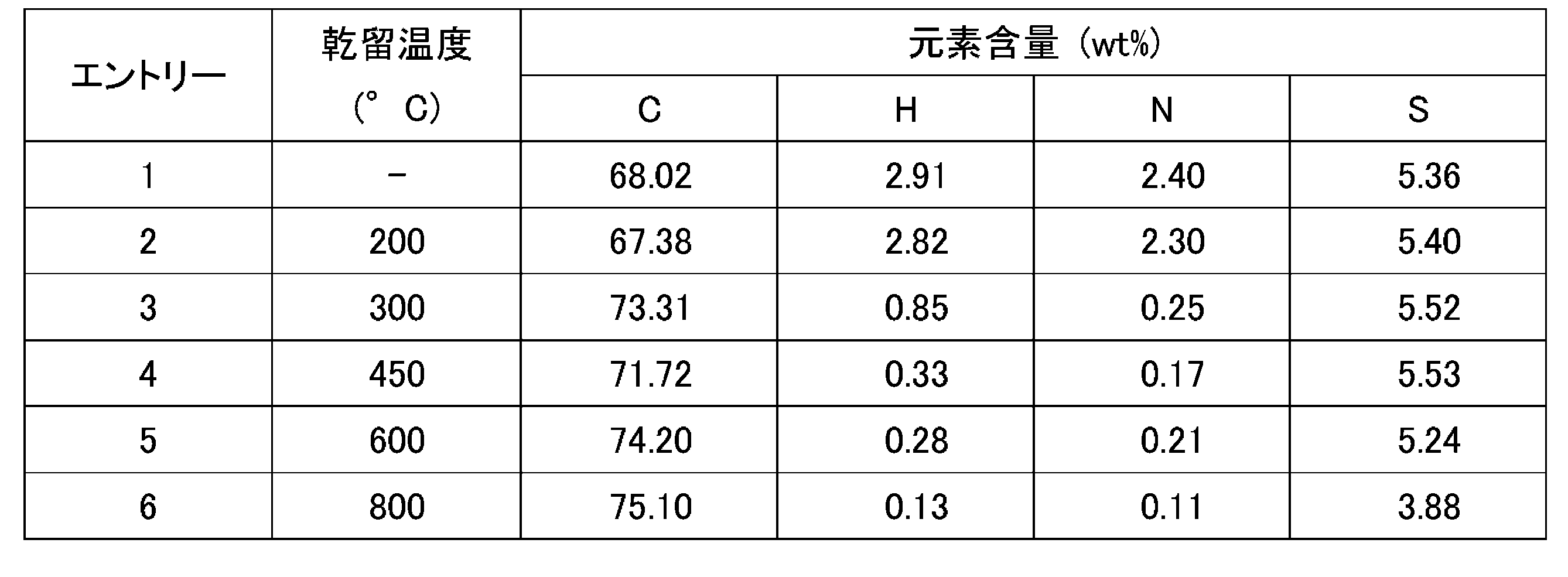
(4)ニッケル・ロジウム乾留触媒の(走査型)透過電子顕微鏡((S)TEM)観察、及びエネルギー分散型X線分光法(EDS)マッピングデータによる分析
実施例1-1において様々な乾留温度(200-800 ℃)で合成したニッケル・ロジウム乾留触媒、及び、ニッケル・ロジウムクロロ錯体[NiIICl(N2S2)RhIIICl(η5-C5Me5)]のそれぞれにつき、(S)TEM観察およびEDSマッピングを行い、ナノ粒子の分析を行なった。ここで、(S)TEM観察およびEDSマッピングは、ニッケル・ロジウム乾留触媒またはニッケル・ロジウムクロロ錯体(5mg)とカーボンブラック(5mg)との混合物のうちの1mgをサンプルとして行なった。
図5に、600℃で合成したニッケル・ロジウム乾留触媒について得られた、(S)TEM観察とEDSマッピングの結果を示した。
また、図20-1に、ニッケル・ロジウムクロロ錯体[NiIICl(N2S2)RhIIICl(η5-C5Me5)](「錯体1」)、および、200℃,230℃でそれぞれ合成したニッケル・ロジウム乾留触媒のそれぞれにつき、図20-2に、250℃,280℃および300℃でそれぞれ合成したニッケル・ロジウム乾留触媒のそれぞれにつき、TEMにより取得した明視野(BF)像、STEMにより取得した環状暗視野(ADF)像、ならびにEDS法により取得したそれぞれの元素(Rh、Ni、S)のEDSマッピングの結果を示した。
図20-1および図20-2の結果からは、以下のことが示されている:
* 200℃で合成したニッケル・ロジウム乾留触媒においては、数nmの粒径からなる微細な触媒粒子が一様に分散している様子が観察された。
* 230℃で合成したニッケル・ロジウム乾留触媒においては、平均粒径が10nmの粒子が、250℃で合成したニッケル・ロジウム乾留触媒においては、平均粒径が20nmの粒子が、280℃で合成したニッケル・ロジウム乾留触媒においては、平均粒径が25nmの粒子が、それぞれ生成していることが観察された。また、EDSマッピングの結果からは、これらの粒子では、Ni、Rh、Sが均一に分布していることが示唆される。
* 300℃以上で合成したニッケル・ロジウム乾留触媒においては、280℃以下で合成したニッケル・ロジウム乾留触媒と比べて、触媒を構成する粒子の粒径が大きく肥大化していることが観察された。また、EDSマッピングの結果からは、300℃以上で合成したニッケル・ロジウム乾留触媒においては、280℃以下で合成したニッケル・ロジウム乾留触媒とは異なり、粒子においてNi、Rh、Sが不均一に分布していることが示唆される(図5も参照のこと)。
以上の結果から、ニッケル・ロジウムクロロ錯体および280℃以下で合成したニッケル・ロジウム乾留触媒においては、触媒を構成する粒子においてNi、Rhがほぼ均一に分布している一方で、300℃以上で合成したニッケル・ロジウム乾留触媒においては、触媒を構成する粒子においてNi、Rh、Sの分布が偏ってくることが示唆される。ここで、本発明者は、触媒を構成する粒子において、Sは、粒子表面をコーティングする態様で分布しているのではなく、その大部分は、NiおよびRhと同じ位置に分布していると推測している。
また、上記ニッケル・イリジウムクロロ錯体およびこれを熱処理して得られるニッケル・イリジウム乾留触媒、並びに、上記ニッケル・ルテニウムヒドリド錯体およびこれを熱処理して得られるニッケル・ルテニウム乾留触媒についても、同様の分析を行った。
その結果、ニッケル・イリジウムクロロ錯体および200℃以下で合成したニッケル・イリジウム乾留触媒においては、触媒を構成する粒子においてNi、Irが均一に分布している一方で、300℃以上で合成したニッケル・イリジウム乾留触媒においては、触媒を構成する粒子においてNi、Ir、Sの分布が偏ってくることが示唆されている。ここで、本発明者は、触媒を構成する粒子において、SおよびNiは、粒子表面をコーティングする態様で分布しているのではなく、それらの大部分は、Irと同じ位置に分布していると推測している。
ニッケル・ルテニウムヒドリド錯体および300℃以下で合成したニッケル・ルテニウム乾留触媒においては、触媒を構成する粒子においてNi、Ruが均一に分布している一方で、400℃以上で合成したニッケル・ルテニウム乾留触媒においては、触媒を構成する粒子においてNi、Ru、Sの分布が偏ってくることが示唆されている。ここで、本発明者は、触媒を構成する粒子において、Sは、粒子表面をコーティングする態様で分布しているのではなく、それらの大部分は、Ni,Ruと同じ位置に分布していると推測している。
IV.酸化・還元反応実験
[実施例2-1]ニッケル・ロジウム乾留触媒を用いたH2酸化反応実験
<メチレンブルーを電子アクセプターに用いたH2酸化反応実験>
実施例1-1において乾留温度を600℃として合成したニッケル・ロジウム乾留触媒と30当量のメチレンブルーを水中(pH5)で混合し、H2雰囲気下(0.1-0.8MPa)、30℃で6時間撹拌した。UV-visスペクトルで生成したメチレンブルーの還元体(ロイコメチレンブルー)を定量し、ターンオーバー数(TON)を算出した。この条件におけるTON[(ロイコメチレンブルーのモル数)/(乾留触媒のモル数)]は、表2に示すように17であった。
[実施例2-1]ニッケル・ロジウム乾留触媒を用いたH2酸化反応実験
<メチレンブルーを電子アクセプターに用いたH2酸化反応実験>
実施例1-1において乾留温度を600℃として合成したニッケル・ロジウム乾留触媒と30当量のメチレンブルーを水中(pH5)で混合し、H2雰囲気下(0.1-0.8MPa)、30℃で6時間撹拌した。UV-visスペクトルで生成したメチレンブルーの還元体(ロイコメチレンブルー)を定量し、ターンオーバー数(TON)を算出した。この条件におけるTON[(ロイコメチレンブルーのモル数)/(乾留触媒のモル数)]は、表2に示すように17であった。
[比較例2-c1]異種二核錯体[NM]を用いたH2酸化反応実験
<メチレンブルーを電子アクセプターに用いたH2酸化反応実験>
乾留の有無による効果を確認するため、前記ニッケル・ロジウム乾留触媒に代えて、ニッケル・ロジウムクロロ錯体を用いたことを除き、実施例2-1と同様の実験を行った。
<メチレンブルーを電子アクセプターに用いたH2酸化反応実験>
乾留の有無による効果を確認するため、前記ニッケル・ロジウム乾留触媒に代えて、ニッケル・ロジウムクロロ錯体を用いたことを除き、実施例2-1と同様の実験を行った。
すなわち、[NiIICl(N2S2)RhIIICl(η5-C5Me5)]と30当量のメチレンブルーを水中(pH7)で混合し、H2雰囲気下(0.1-0.8MPa)、30℃で6時間撹拌した。UV-visスペクトルで生成したメチレンブルーの還元体(ロイコメチレンブルー)を定量し、ターンオーバー数(TON)を算出した。この条件におけるTONは、表2に示すように4であった。
[実施例3-1]ニッケル・ロジウム乾留触媒を用いたO2還元反応実験
実施例1-1において乾留温度を450℃として合成したニッケル・ロジウム乾留触媒のリン酸緩衝溶液(pH7)にH2を20分間バブリングした。反応溶液に18O2(2.0mL)をインジェクションし、25℃で5時間撹拌した。反応溶液をショートシリカゲルカラムに通すことで、触媒を除去した。反応溶液中に生成したH2 18O量をGC-MSにより定量し、ターンオーバー数(TON)を算出した。TON[{(H2 18Oのモル数)/(乾留触媒のモル数)}/2]は、表2に示すように、乾留触媒基準で1.7と求められた。
実施例1-1において乾留温度を450℃として合成したニッケル・ロジウム乾留触媒のリン酸緩衝溶液(pH7)にH2を20分間バブリングした。反応溶液に18O2(2.0mL)をインジェクションし、25℃で5時間撹拌した。反応溶液をショートシリカゲルカラムに通すことで、触媒を除去した。反応溶液中に生成したH2 18O量をGC-MSにより定量し、ターンオーバー数(TON)を算出した。TON[{(H2 18Oのモル数)/(乾留触媒のモル数)}/2]は、表2に示すように、乾留触媒基準で1.7と求められた。
[比較例3-c1]異種二核錯体[NM]を用いたO2還元反応実験
乾留の有無による効果を確認するため、前記ニッケル・ロジウム乾留触媒に代えて、ニッケル・ロジウムクロロ錯体を用いたことを除き、実施例3-1と同様の実験を行った。
乾留の有無による効果を確認するため、前記ニッケル・ロジウム乾留触媒に代えて、ニッケル・ロジウムクロロ錯体を用いたことを除き、実施例3-1と同様の実験を行った。
すなわち、[NiIICl(N2S2)RhIIICl(η5-C5Me5)]のリン酸緩衝溶液(pH 7)にH2を20分間バブリングした。反応溶液に18O2(2.0 mL)をインジェクションし、25℃で5時間撹拌した。反応溶液をショートシリカゲルカラムに通すことで、錯体を除去した。反応溶液中に生成したH2
18O量をGC-MSにより定量し、ターンオーバー数(TON)を算出した。TON[{(H2
18Oのモル数)/(錯体のモル数)}/2]は、表2に示すように、NiRh錯体基準で0.5と求められた。
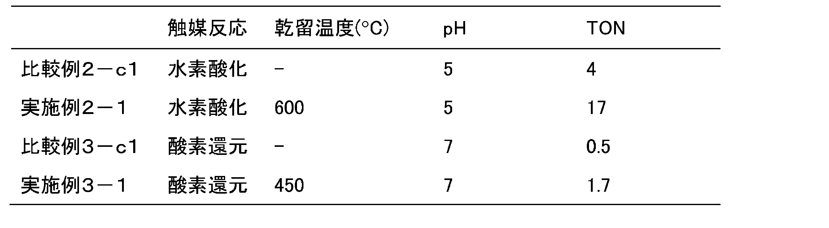
V.金属錯体または乾留錯体を電極触媒として有する燃料電池についての水素-酸素燃料電池評価
V-1A.ニッケル・ロジウムクロロ錯体あるいはニッケル・ロジウム乾留触媒をアノード触媒として有する燃料電池についての水素-酸素燃料電池評価
[比較例4A-c0]ニッケル・ロジウムクロロ錯体をアノード触媒として用いたときの燃料電池評価実験
ニッケル・ロジウムクロロ錯体[NiIICl(N2S2)RhIIICl(η5-C5Me5)](5.0mg)とカーボンブラック(5.0mg)とを混合し、得られる混合物を耐水性カーボンクロス(5cm2)上に塗布することで、アノード触媒としてニッケル・ロジウムクロロ錯体を含むアノード電極(以下「アノード電極NiRhc0」)を作成した。
V-1A.ニッケル・ロジウムクロロ錯体あるいはニッケル・ロジウム乾留触媒をアノード触媒として有する燃料電池についての水素-酸素燃料電池評価
[比較例4A-c0]ニッケル・ロジウムクロロ錯体をアノード触媒として用いたときの燃料電池評価実験
ニッケル・ロジウムクロロ錯体[NiIICl(N2S2)RhIIICl(η5-C5Me5)](5.0mg)とカーボンブラック(5.0mg)とを混合し、得られる混合物を耐水性カーボンクロス(5cm2)上に塗布することで、アノード触媒としてニッケル・ロジウムクロロ錯体を含むアノード電極(以下「アノード電極NiRhc0」)を作成した。
一方、Pt/C(11mg)をナフィオン(商標)溶液(59mg:ナフィオン/カーボン比=2(wt/wt))に加えて1時間超音波処理して得られる懸濁液を、耐水性カーボンクロス(5cm2)上に塗布することで、カソード触媒としてPt/Cを含むカソード電極(以下「カソード電極Pt」)を作成した。
また、ナフィオン(商標)膜212につき、3%過酸化水素水で1時間、1.0M硫酸水で1時間、および、脱イオン水で1時間、それぞれ煮沸することにより前処理を行った。
前記前処理を行ったナフィオン(商標)膜212を、前記アノード電極NiRhc0と前記カソード電極Ptとではさみ、膜電極接合体(MEA)を得た。このMEAは、カーボンクロスからなる層と、アノード触媒を含む層と、ナフィオン(商標)膜212からなる層と、カソード触媒を含む層と、カーボンクロスからなる層とをこの順番で有している。このMEAにおいて、ナフィオン(商標)膜212は、プロトン伝導膜として機能する。このMEAを燃料電池セル(5cm2)に組み込むことで、図6に示す構成を有する燃料電池とした。この燃料電池は、MEAの両側に、流路を内蔵した1対の集電板を有している。ここで、燃料電池の外部から導入されるアノードガスは、アノード側に配された集電板を通じてアノードに供給され、燃料電池の外部から導入されるカソードガスは、カソード側に配された集電板を通じてカソードに供給される。
前記前処理を行ったナフィオン(商標)膜212を、前記アノード電極NiRhc0と前記カソード電極Ptとではさみ、膜電極接合体(MEA)を得た。このMEAは、カーボンクロスからなる層と、アノード触媒を含む層と、ナフィオン(商標)膜212からなる層と、カソード触媒を含む層と、カーボンクロスからなる層とをこの順番で有している。このMEAにおいて、ナフィオン(商標)膜212は、プロトン伝導膜として機能する。このMEAを燃料電池セル(5cm2)に組み込むことで、図6に示す構成を有する燃料電池とした。この燃料電池は、MEAの両側に、流路を内蔵した1対の集電板を有している。ここで、燃料電池の外部から導入されるアノードガスは、アノード側に配された集電板を通じてアノードに供給され、燃料電池の外部から導入されるカソードガスは、カソード側に配された集電板を通じてカソードに供給される。
得られた燃料電池につき、アノードガスとして水素、カソードガスとして酸素を用い、60℃での燃料電池評価を行った。ここで、燃料電池評価は、燃料電池につきリニアスイープボルタンメトリーを用いて電流-電位特性を測定し、得られた電流-電圧特性曲線から最大電力密度を算出することによって行った。その結果、図9と表3に示すように電池として機能した。
[比較例4A-c1]乾留温度100℃で合成したニッケル・ロジウム乾留触媒をアノード触媒として用いたときの燃料電池評価実験
実施例1-1において乾留温度100℃で合成したニッケル・ロジウム乾留触媒(以下「NiRh乾留触媒100」)(5.0mg)を耐水性カーボンクロス(5cm2)上に塗布することで、アノード触媒としてNiRh乾留触媒100を含むアノード電極(以下「アノード電極NiRhc1」)を作成した。
実施例1-1において乾留温度100℃で合成したニッケル・ロジウム乾留触媒(以下「NiRh乾留触媒100」)(5.0mg)を耐水性カーボンクロス(5cm2)上に塗布することで、アノード触媒としてNiRh乾留触媒100を含むアノード電極(以下「アノード電極NiRhc1」)を作成した。
そして、アノード電極NiRhc0に代えてこのアノード電極NiRhc1を用いたことを除いては比較例4A-c0と同様に、膜電極接合体(MEA)および燃料電池の作成、並びに、燃料電池評価を行った。その結果、図9と表3に示すように電池として機能した。
[比較例4A-c2]乾留温度200℃で合成したニッケル・ロジウム乾留触媒をアノード触媒として用いたときの燃料電池評価実験
NiRh乾留触媒100に代えて、実施例1-1において乾留温度200℃で合成したニッケル・ロジウム乾留触媒(以下「NiRh乾留触媒200」)を用いたことを除いては比較例4A-c1と同様にアノード電極(以下「アノード電極NiRhc2」)、膜電極接合体(MEA)および燃料電池の作成、並びに、燃料電池評価を行った。その結果、図9と表3に示すように電池として機能した。
NiRh乾留触媒100に代えて、実施例1-1において乾留温度200℃で合成したニッケル・ロジウム乾留触媒(以下「NiRh乾留触媒200」)を用いたことを除いては比較例4A-c1と同様にアノード電極(以下「アノード電極NiRhc2」)、膜電極接合体(MEA)および燃料電池の作成、並びに、燃料電池評価を行った。その結果、図9と表3に示すように電池として機能した。
[実施例4A-1]乾留温度300℃で合成したニッケル・ロジウム乾留触媒をアノード触媒として用いたときの燃料電池評価実験
NiRh乾留触媒100に代えて、実施例1-1において乾留温度300℃で合成したニッケル・ロジウム乾留触媒(以下「NiRh乾留触媒300」)を用いたことを除いては比較例4A-c1と同様にアノード電極(以下「アノード電極NiRh1」)、膜電極接合体(MEA)および燃料電池の作成、並びに、燃料電池評価を行った。その結果、図9と表3に示すように電池として機能した。
NiRh乾留触媒100に代えて、実施例1-1において乾留温度300℃で合成したニッケル・ロジウム乾留触媒(以下「NiRh乾留触媒300」)を用いたことを除いては比較例4A-c1と同様にアノード電極(以下「アノード電極NiRh1」)、膜電極接合体(MEA)および燃料電池の作成、並びに、燃料電池評価を行った。その結果、図9と表3に示すように電池として機能した。
[実施例4A-2]乾留温度400℃で合成したニッケル・ロジウム乾留触媒をアノード触媒として用いたときの燃料電池評価実験
NiRh乾留触媒100に代えて、実施例1-1において乾留温度400℃で合成したニッケル・ロジウム乾留触媒(以下「NiRh乾留触媒400」)を用いたことを除いては比較例4A-c1と同様にアノード電極(以下「アノード電極NiRh2」)、膜電極接合体(MEA)および燃料電池の作成、並びに、燃料電池評価を行った。その結果、図9と表3に示すように電池として機能した。
NiRh乾留触媒100に代えて、実施例1-1において乾留温度400℃で合成したニッケル・ロジウム乾留触媒(以下「NiRh乾留触媒400」)を用いたことを除いては比較例4A-c1と同様にアノード電極(以下「アノード電極NiRh2」)、膜電極接合体(MEA)および燃料電池の作成、並びに、燃料電池評価を行った。その結果、図9と表3に示すように電池として機能した。
[実施例4A-3]乾留温度500℃で合成したニッケル・ロジウム乾留触媒をアノード触媒として用いたときの燃料電池評価実験
NiRh乾留触媒100に代えて、実施例1-1において乾留温度500℃で合成したニッケル・ロジウム乾留触媒(以下「NiRh乾留触媒500」)を用いたことを除いては比較例4A-c1と同様にアノード電極(以下「アノード電極NiRh3」)、膜電極接合体(MEA)および燃料電池の作成、並びに、燃料電池評価を行った。その結果、図9と表3に示すように電池として機能した。
NiRh乾留触媒100に代えて、実施例1-1において乾留温度500℃で合成したニッケル・ロジウム乾留触媒(以下「NiRh乾留触媒500」)を用いたことを除いては比較例4A-c1と同様にアノード電極(以下「アノード電極NiRh3」)、膜電極接合体(MEA)および燃料電池の作成、並びに、燃料電池評価を行った。その結果、図9と表3に示すように電池として機能した。
[実施例4A-4]乾留温度600℃で合成したニッケル・ロジウム乾留触媒をアノード触媒として用いたときの燃料電池評価実験
NiRh乾留触媒100に代えて、実施例1-1において乾留温度600℃で合成したニッケル・ロジウム乾留触媒(以下「NiRh乾留触媒600」)を用いたことを除いては比較例4A-c1と同様にアノード電極(以下「アノード電極NiRh4」)、膜電極接合体(MEA)および燃料電池の作成、並びに、燃料電池評価を行った。その結果、図9と表3に示すように電池として機能した。また、図7に、燃料電池評価によって得られた電流密度に対するセル電圧及び出力密度の関係を表すチャートを示す。
NiRh乾留触媒100に代えて、実施例1-1において乾留温度600℃で合成したニッケル・ロジウム乾留触媒(以下「NiRh乾留触媒600」)を用いたことを除いては比較例4A-c1と同様にアノード電極(以下「アノード電極NiRh4」)、膜電極接合体(MEA)および燃料電池の作成、並びに、燃料電池評価を行った。その結果、図9と表3に示すように電池として機能した。また、図7に、燃料電池評価によって得られた電流密度に対するセル電圧及び出力密度の関係を表すチャートを示す。
[実施例4A-5]乾留温度700℃で合成したニッケル・ロジウム乾留触媒をアノード触媒として用いたときの燃料電池評価実験
NiRh乾留触媒100に代えて、実施例1-1において乾留温度700℃で合成したニッケル・ロジウム乾留触媒(以下「NiRh乾留触媒700」)を用いたことを除いては比較例4A-c1と同様にアノード電極(以下「アノード電極NiRh5」)、膜電極接合体(MEA)および燃料電池の作成、並びに、燃料電池評価を行った。その結果、図9と表3に示すように電池として機能した。
NiRh乾留触媒100に代えて、実施例1-1において乾留温度700℃で合成したニッケル・ロジウム乾留触媒(以下「NiRh乾留触媒700」)を用いたことを除いては比較例4A-c1と同様にアノード電極(以下「アノード電極NiRh5」)、膜電極接合体(MEA)および燃料電池の作成、並びに、燃料電池評価を行った。その結果、図9と表3に示すように電池として機能した。
[実施例4A-6]乾留温度800℃で合成したニッケル・ロジウム乾留触媒をアノード触媒として用いたときの燃料電池評価実験
NiRh乾留触媒100に代えて、実施例1-1において乾留温度800℃で合成したニッケル・ロジウム乾留触媒(以下「NiRh乾留触媒800」)を用いたことを除いては比較例4A-c1と同様にアノード電極(以下「アノード電極NiRh6」)、膜電極接合体(MEA)および燃料電池の作成、並びに、燃料電池評価を行った。その結果、図9と表3に示すように電池として機能した。
NiRh乾留触媒100に代えて、実施例1-1において乾留温度800℃で合成したニッケル・ロジウム乾留触媒(以下「NiRh乾留触媒800」)を用いたことを除いては比較例4A-c1と同様にアノード電極(以下「アノード電極NiRh6」)、膜電極接合体(MEA)および燃料電池の作成、並びに、燃料電池評価を行った。その結果、図9と表3に示すように電池として機能した。
V-1B.ニッケル・イリジウム乾留触媒をアノード触媒として有する燃料電池についての水素-酸素燃料電池評価
[実施例4B-1]乾留温度600℃で合成したニッケル・イリジウム乾留触媒をアノード触媒として用いたときの燃料電池評価実験
実施例1-2において乾留温度600℃で合成したニッケル・イリジウム乾留触媒(以下「NiIr乾留触媒600」)(5.0mg)を耐水性カーボンクロス(5cm2)上に塗布することで、アノード電極(以下「アノード電極NiIr1」)を作成した。
[実施例4B-1]乾留温度600℃で合成したニッケル・イリジウム乾留触媒をアノード触媒として用いたときの燃料電池評価実験
実施例1-2において乾留温度600℃で合成したニッケル・イリジウム乾留触媒(以下「NiIr乾留触媒600」)(5.0mg)を耐水性カーボンクロス(5cm2)上に塗布することで、アノード電極(以下「アノード電極NiIr1」)を作成した。
そして、アノード電極NiRhc0に代えてこのアノード電極NiIr1を用いたことを除いては比較例4A-c0と同様に、膜電極接合体(MEA)および燃料電池の作成、並びに、燃料電池評価を行った。その結果、表3に示すように電池として機能した。
V-1C.ニッケル・ルテニウム乾留触媒をアノード触媒として有する燃料電池についての水素-酸素燃料電池評価
[実施例4C-1]乾留温度600 ℃でニッケル・ルテニウム乾留触媒をアノード触媒として用いたときの燃料電池評価実験
実施例1-3において乾留温度600℃で合成したニッケル・ルテニウム乾留触媒(以下「NiRu乾留触媒600」)(5.0mg)をカーボンクロス(5cm2)上に塗布することで、アノード触媒としてニッケル・ルテニウム乾留触媒600を含むアノード電極(以下「アノード電極NiRu1」)を作成した。
[実施例4C-1]乾留温度600 ℃でニッケル・ルテニウム乾留触媒をアノード触媒として用いたときの燃料電池評価実験
実施例1-3において乾留温度600℃で合成したニッケル・ルテニウム乾留触媒(以下「NiRu乾留触媒600」)(5.0mg)をカーボンクロス(5cm2)上に塗布することで、アノード触媒としてニッケル・ルテニウム乾留触媒600を含むアノード電極(以下「アノード電極NiRu1」)を作成した。
そして、アノード電極NiRhc0に代えてこのアノード電極NiRu1を用いたことを除いては比較例4A-c0と同様に、膜電極接合体(MEA)および燃料電池の作成、並びに、燃料電池評価を行った。その結果、表3に示すように電池として機能した。
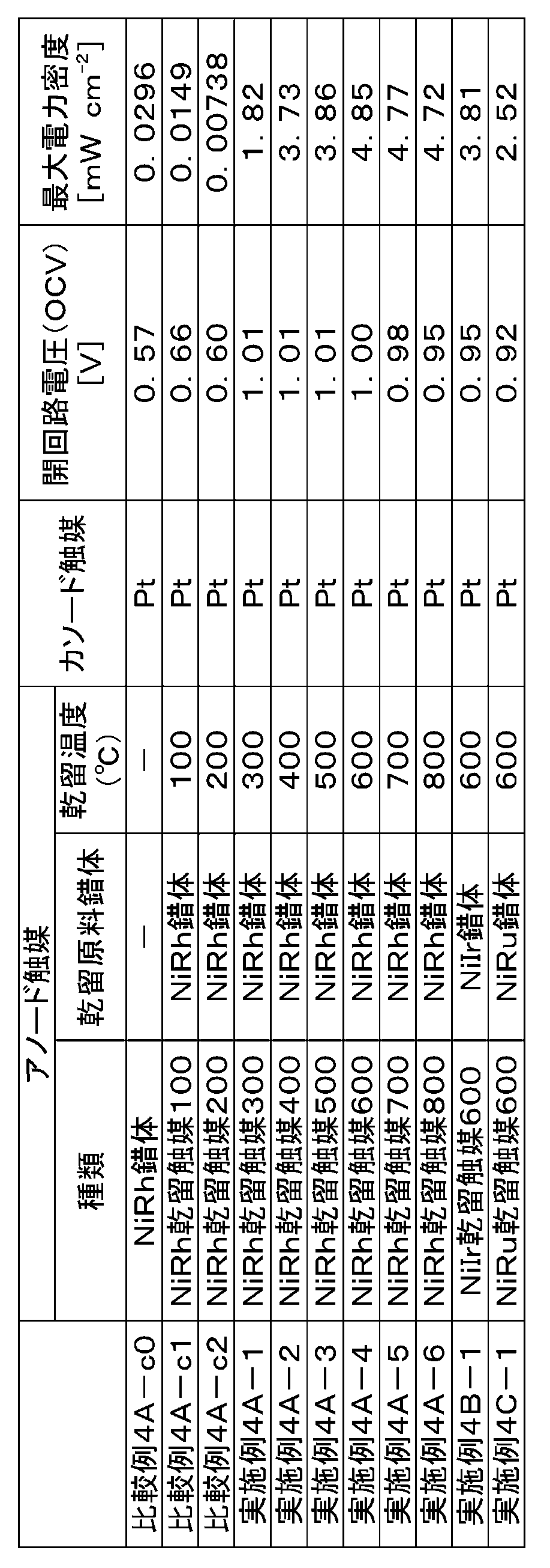
V-2A.ニッケル・ロジウムクロロ錯体あるいはニッケル・ロジウム乾留触媒をカソード触媒として有する燃料電池についての水素-酸素燃料電池評価
[比較例5A-c0]ニッケル・ロジウムクロロ錯体をカソード触媒として用いたときの燃料電池評価実験
ニッケル・ロジウムクロロ錯体[NiIICl(N2S2)RhIIICl(η5-C5Me5)](5.0mg)とカーボンブラック(5.0mg)とを混合し、得られる混合物を耐水性カーボンクロス(5cm2)上に塗布することで、カソード触媒としてニッケル・ロジウムクロロ錯体を含むカソード電極(以下「カソード電極NiRhc0」)を作成した。
[比較例5A-c0]ニッケル・ロジウムクロロ錯体をカソード触媒として用いたときの燃料電池評価実験
ニッケル・ロジウムクロロ錯体[NiIICl(N2S2)RhIIICl(η5-C5Me5)](5.0mg)とカーボンブラック(5.0mg)とを混合し、得られる混合物を耐水性カーボンクロス(5cm2)上に塗布することで、カソード触媒としてニッケル・ロジウムクロロ錯体を含むカソード電極(以下「カソード電極NiRhc0」)を作成した。
一方、Pt/C(11mg)をナフィオン(商標)溶液(59mg:ナフィオン/カーボン比=2(wt/wt))に加えて1時間超音波処理して得られる懸濁液を、耐水性カーボンクロス(5cm2)上に塗布することで、アノード触媒としてPt/Cを含むアノード電極(以下「アノード電極Pt」)を作成した。
また、ナフィオン(商標)膜212につき、3%過酸化水素水で1時間、1.0M硫酸水で1時間、および、脱イオン水で1時間、それぞれ煮沸することにより前処理を行った。
前記前処理を行ったナフィオン(商標)膜212を、前記カソード電極NiRhc0と前記アノード電極Ptとではさみ、膜電極接合体(MEA)を得た。このMEAは、カーボンクロスからなる層と、アノード触媒を含む層と、ナフィオン(商標)膜212からなる層と、カソード触媒を含む層と、カーボンクロスからなる層とをこの順番で有している。このMEAを燃料電池セル(5cm2)に組み込むことで燃料電池とした。
前記前処理を行ったナフィオン(商標)膜212を、前記カソード電極NiRhc0と前記アノード電極Ptとではさみ、膜電極接合体(MEA)を得た。このMEAは、カーボンクロスからなる層と、アノード触媒を含む層と、ナフィオン(商標)膜212からなる層と、カソード触媒を含む層と、カーボンクロスからなる層とをこの順番で有している。このMEAを燃料電池セル(5cm2)に組み込むことで燃料電池とした。
得られた燃料電池につき、アノードガスとして水素、カソードガスとして酸素を用い、60℃での燃料電池評価を行った。ここで、燃料電池評価は、燃料電池につきリニアスイープボルタンメトリーを用いて電流-電位特性を測定し、得られた電流-電圧特性曲線から最大電力密度を算出することによって行った。その結果、表4に示すように電池として機能した。
[比較例5A-c1]乾留温度100℃で合成したニッケル・ロジウム乾留触媒をカソード触媒として用いたときの燃料電池評価実験
実施例1-1において乾留温度100℃で合成したニッケル・ロジウム乾留触媒(以下「NiRh乾留触媒100」)(5.0mg)を耐水性カーボンクロス(5cm2)上に塗布することで、カソード触媒としてNiRh乾留触媒100を含むカソード電極(以下「カソード電極NiRhc1」)を作成した。
実施例1-1において乾留温度100℃で合成したニッケル・ロジウム乾留触媒(以下「NiRh乾留触媒100」)(5.0mg)を耐水性カーボンクロス(5cm2)上に塗布することで、カソード触媒としてNiRh乾留触媒100を含むカソード電極(以下「カソード電極NiRhc1」)を作成した。
そして、カソード電極NiRhc0に代えてこのカソード電極NiRhc1を用いたことを除いては比較例5A-c0と同様に、膜電極接合体(MEA)および燃料電池の作成、並びに、燃料電池評価を行った。その結果、図10と表4に示すように電池として機能した。
[比較例5A-c2]乾留温度200℃で合成したニッケル・ロジウム乾留触媒をカソード触媒として用いたときの燃料電池評価実験
NiRh乾留触媒100に代えて、実施例1-1において乾留温度200 ℃で合成したニッケル・ロジウム乾留触媒(以下「NiRh乾留触媒200」)を用いたことを除いては比較例5A-c1と同様にカソード電極(以下「カソード電極NiRhc2」)、膜電極接合体(MEA)および燃料電池の作成、並びに、燃料電池評価を行った。その結果、図10と表4に示すように電池として機能した。
NiRh乾留触媒100に代えて、実施例1-1において乾留温度200 ℃で合成したニッケル・ロジウム乾留触媒(以下「NiRh乾留触媒200」)を用いたことを除いては比較例5A-c1と同様にカソード電極(以下「カソード電極NiRhc2」)、膜電極接合体(MEA)および燃料電池の作成、並びに、燃料電池評価を行った。その結果、図10と表4に示すように電池として機能した。
[実施例5A-1]乾留温度300℃で合成したニッケル・ロジウム乾留触媒をカソード触媒として用いたときの燃料電池評価実験
NiRh乾留触媒100に代えて、実施例1-1において乾留温度300℃で作成したニッケル・ロジウム乾留触媒(以下「NiRh乾留触媒300」)を用いたことを除いては比較例5A-c1と同様にカソード電極(以下「カソード電極NiRh1」)、膜電極接合体(MEA)および燃料電池の作成、並びに、燃料電池評価を行った。その結果、図10と表4に示すように電池として機能した。
NiRh乾留触媒100に代えて、実施例1-1において乾留温度300℃で作成したニッケル・ロジウム乾留触媒(以下「NiRh乾留触媒300」)を用いたことを除いては比較例5A-c1と同様にカソード電極(以下「カソード電極NiRh1」)、膜電極接合体(MEA)および燃料電池の作成、並びに、燃料電池評価を行った。その結果、図10と表4に示すように電池として機能した。
[実施例5A-2]乾留温度400℃で合成したニッケル・ロジウム乾留触媒をカソード触媒として用いたときの燃料電池評価実験
NiRh乾留触媒100に代えて、実施例1-1において乾留温度400℃で合成したニッケル・ロジウム乾留触媒(以下「NiRh乾留触媒400」)を用いたことを除いては比較例5A-c1と同様にカソード電極(以下「カソード電極NiRh2」)、膜電極接合体(MEA)および燃料電池の作成、並びに、燃料電池評価を行った。その結果、図10と表4に示すように電池として機能した。
NiRh乾留触媒100に代えて、実施例1-1において乾留温度400℃で合成したニッケル・ロジウム乾留触媒(以下「NiRh乾留触媒400」)を用いたことを除いては比較例5A-c1と同様にカソード電極(以下「カソード電極NiRh2」)、膜電極接合体(MEA)および燃料電池の作成、並びに、燃料電池評価を行った。その結果、図10と表4に示すように電池として機能した。
[実施例5A-3]乾留温度500℃で合成したニッケル・ロジウム乾留触媒をカソード触媒として用いたときの燃料電池評価実験
NiRh乾留触媒100に代えて、実施例1-1において乾留温度500℃で合成したニッケル・ロジウム乾留触媒(以下「NiRh乾留触媒500」)を用いたことを除いては比較例5A-c1と同様にカソード電極(以下「カソード電極NiRh3」)、膜電極接合体(MEA)および燃料電池の作成、並びに、燃料電池評価を行った。その結果、図10と表4に示すように電池として機能した。
NiRh乾留触媒100に代えて、実施例1-1において乾留温度500℃で合成したニッケル・ロジウム乾留触媒(以下「NiRh乾留触媒500」)を用いたことを除いては比較例5A-c1と同様にカソード電極(以下「カソード電極NiRh3」)、膜電極接合体(MEA)および燃料電池の作成、並びに、燃料電池評価を行った。その結果、図10と表4に示すように電池として機能した。
[実施例5A-4]乾留温度600℃で合成したニッケル・ロジウム乾留触媒をカソード触媒として用いたときの燃料電池評価実験
NiRh乾留触媒100に代えて、実施例1-1において乾留温度600℃で合成したニッケル・ロジウム乾留触媒(以下「NiRh乾留触媒600」)を用いたことを除いては比較例5A-c1と同様にカソード電極(以下「カソード電極NiRh4」)、膜電極接合体(MEA)および燃料電池の作成、並びに、燃料電池評価を行った。その結果、図10と表4に示すように電池として機能した。また、図8に、燃料電池評価によって得られた電流密度に対するセル電圧及び出力密度の関係を表すチャートを示す。
NiRh乾留触媒100に代えて、実施例1-1において乾留温度600℃で合成したニッケル・ロジウム乾留触媒(以下「NiRh乾留触媒600」)を用いたことを除いては比較例5A-c1と同様にカソード電極(以下「カソード電極NiRh4」)、膜電極接合体(MEA)および燃料電池の作成、並びに、燃料電池評価を行った。その結果、図10と表4に示すように電池として機能した。また、図8に、燃料電池評価によって得られた電流密度に対するセル電圧及び出力密度の関係を表すチャートを示す。
[実施例5A-5]乾留温度700℃で合成したニッケル・ロジウム乾留触媒をカソード触媒として用いたときの燃料電池評価実験
NiRh乾留触媒100に代えて、実施例1-1において乾留温度700℃で合成したニッケル・ロジウム乾留触媒(以下「NiRh乾留触媒700」)を用いたことを除いては比較例5A-c1と同様にカソード電極(以下「カソード電極NiRh5」)、膜電極接合体(MEA)および燃料電池の作成、並びに、燃料電池評価を行った。その結果、図10と表4に示すように電池として機能した。
NiRh乾留触媒100に代えて、実施例1-1において乾留温度700℃で合成したニッケル・ロジウム乾留触媒(以下「NiRh乾留触媒700」)を用いたことを除いては比較例5A-c1と同様にカソード電極(以下「カソード電極NiRh5」)、膜電極接合体(MEA)および燃料電池の作成、並びに、燃料電池評価を行った。その結果、図10と表4に示すように電池として機能した。
[実施例5A-6]乾留温度800℃で合成したニッケル・ロジウム乾留触媒をカソード触媒として用いたときの燃料電池評価実験
NiRh乾留触媒100に代えて、実施例1-1において乾留温度800℃で合成したニッケル・ロジウム乾留触媒(以下「NiRh乾留触媒800」)を用いたことを除いては比較例5A-c1と同様にカソード電極(以下「カソード電極NiRh6」)、膜電極接合体(MEA)および燃料電池の作成、並びに、燃料電池評価を行った。その結果、図10と表4に示すように電池として機能した。
NiRh乾留触媒100に代えて、実施例1-1において乾留温度800℃で合成したニッケル・ロジウム乾留触媒(以下「NiRh乾留触媒800」)を用いたことを除いては比較例5A-c1と同様にカソード電極(以下「カソード電極NiRh6」)、膜電極接合体(MEA)および燃料電池の作成、並びに、燃料電池評価を行った。その結果、図10と表4に示すように電池として機能した。
V-2B.ニッケル・イリジウム乾留触媒をカソード触媒として有する燃料電池についての水素-酸素燃料電池評価
[実施例5B-1]乾留温度600℃で合成したニッケル・イリジウム乾留触媒をカソード触媒として用いたときの燃料電池評価実験
実施例1-2において乾留温度600℃で合成したニッケル・イリジウム乾留触媒(以下「NiIr乾留触媒600」)(5.0mg)を耐水性カーボンクロス(5cm2)上に塗布することで、カソード電極(以下「カソード電極NiIr1」)を作成した。
[実施例5B-1]乾留温度600℃で合成したニッケル・イリジウム乾留触媒をカソード触媒として用いたときの燃料電池評価実験
実施例1-2において乾留温度600℃で合成したニッケル・イリジウム乾留触媒(以下「NiIr乾留触媒600」)(5.0mg)を耐水性カーボンクロス(5cm2)上に塗布することで、カソード電極(以下「カソード電極NiIr1」)を作成した。
そして、カソード電極NiRhc0に代えてこのカソード電極NiIr1を用いたことを除いては比較例5A-c0と同様に、膜電極接合体(MEA)および燃料電池の作成、並びに、燃料電池評価を行った。その結果、表4に示すように電池として機能した。
V-2C.ニッケル・ルテニウム乾留触媒をカソード触媒として有する燃料電池についての水素-酸素燃料電池評価
[実施例5C-1]乾留温度600℃で合成したニッケル・ルテニウム乾留触媒をカソード触媒として用いたときの燃料電池評価実験
実施例1-3において乾留温度600℃で合成したニッケル・ルテニウム乾留触媒(以下「NiRu乾留触媒600」)(5.0mg)を耐水性カーボンクロス(5cm2)上に塗布することで、カソード電極(以下「カソード電極NiRu1」)を作成した。
[実施例5C-1]乾留温度600℃で合成したニッケル・ルテニウム乾留触媒をカソード触媒として用いたときの燃料電池評価実験
実施例1-3において乾留温度600℃で合成したニッケル・ルテニウム乾留触媒(以下「NiRu乾留触媒600」)(5.0mg)を耐水性カーボンクロス(5cm2)上に塗布することで、カソード電極(以下「カソード電極NiRu1」)を作成した。
そして、カソード電極NiRhc0に代えてこのカソード電極NiRu1を用いたことを除いては比較例5A-c0と同様に、膜電極接合体(MEA)および燃料電池の作成、並びに、燃料電池評価を行った。その結果、表4に示すように電池として機能した。
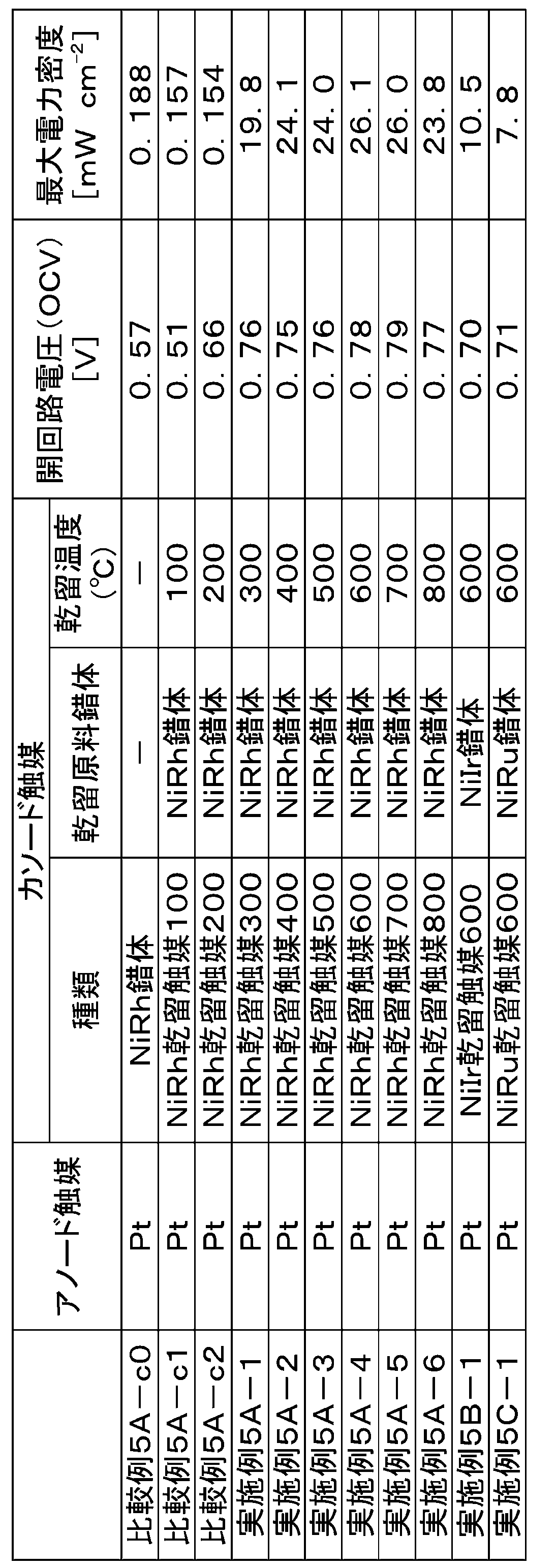
V-3A.ニッケル・ロジウムクロロ錯体あるいはニッケル・ロジウム乾留触媒をアノード触媒及びカソード触媒として有する燃料電池についての水素-酸素燃料電池評価
[比較例6A-c0]ニッケル・ロジウムクロロ錯体をアノード触媒とカソード触媒の両方に用いたときの水素-酸素燃料電池評価
ニッケル・ロジウムクロロ錯体[NiIICl(N2S2)RhIIICl(η5-C5Me5)](5.0mg)とカーボンブラック(5.0mg)とを混合し、得られる混合物を耐水性カーボンクロス(5cm2)上に塗布することで、アノード電極(以下「アノード電極NiRhc0」)及びカソード電極(以下「カソード電極NiRhc0」)を作成した。
[比較例6A-c0]ニッケル・ロジウムクロロ錯体をアノード触媒とカソード触媒の両方に用いたときの水素-酸素燃料電池評価
ニッケル・ロジウムクロロ錯体[NiIICl(N2S2)RhIIICl(η5-C5Me5)](5.0mg)とカーボンブラック(5.0mg)とを混合し、得られる混合物を耐水性カーボンクロス(5cm2)上に塗布することで、アノード電極(以下「アノード電極NiRhc0」)及びカソード電極(以下「カソード電極NiRhc0」)を作成した。
また、ナフィオン(商標)膜212につき、3%過酸化水素水で1時間、1.0M硫酸水で1時間、および、脱イオン水で1時間、それぞれ煮沸することにより前処理を行った。
前記前処理を行ったナフィオン(商標)膜212を、前記カソード電極NiRhc0と前記アノード電極NiRhc0とではさみ、膜電極接合体(MEA)を得た。このMEAは、カーボンクロスからなる層と、アノード触媒を含む層と、ナフィオン(商標)膜212からなる層と、カソード触媒を含む層と、カーボンクロスからなる層とをこの順番で有している。このMEAを燃料電池セル(5cm2)に組み込むことで燃料電池とした。
前記前処理を行ったナフィオン(商標)膜212を、前記カソード電極NiRhc0と前記アノード電極NiRhc0とではさみ、膜電極接合体(MEA)を得た。このMEAは、カーボンクロスからなる層と、アノード触媒を含む層と、ナフィオン(商標)膜212からなる層と、カソード触媒を含む層と、カーボンクロスからなる層とをこの順番で有している。このMEAを燃料電池セル(5cm2)に組み込むことで燃料電池とした。
得られた燃料電池につき、燃料電池評価を行った。ここで、燃料電池評価は、燃料電池につきリニアスイープボルタンメトリーを用いて電流-電位特性を測定し、得られた電流-電圧特性曲線から最大電力密度を算出することによって行った。その結果、表5に示すように電池として機能した。
[実施例6A-1]ニッケル・ロジウム乾留触媒をアノードとカソード触媒の両方に用いた水素-酸素燃料電池評価
実施例1-1において乾留温度600℃で作成したニッケル・ロジウム乾留触媒(以下「NiRh乾留触媒100」)(5.0mg)を耐水性カーボンクロス(5cm2)上に塗布することで、アノード電極(以下「アノード電極NiRh1」)及びカソード電極(以下「カソード電極NiRh1」)を作成した。
実施例1-1において乾留温度600℃で作成したニッケル・ロジウム乾留触媒(以下「NiRh乾留触媒100」)(5.0mg)を耐水性カーボンクロス(5cm2)上に塗布することで、アノード電極(以下「アノード電極NiRh1」)及びカソード電極(以下「カソード電極NiRh1」)を作成した。
そして、アノード電極NiRhc0に代えてアノード電極NiRhc1を用い、かつ、カソード電極NiRhc0に代えてカソード電極NiRhc1を用いたことを除いては比較例6A-c0と同様に、膜電極接合体(MEA)および燃料電池の作成、並びに、燃料電池評価を行った。その結果、図11と表5に示すように電池として機能した。
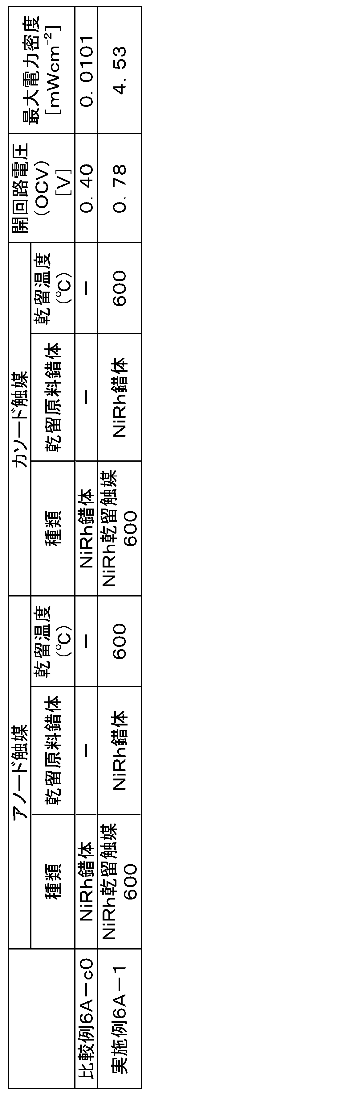
VI.金属錯体または乾留錯体を電極触媒として有する燃料電池についての電極触媒能評価
[比較例7-c1]ニッケル・ロジウムクロロ錯体をアノード電極触媒、白金をカソード電極触媒に用いた水素―酸素燃料電池のターフェルプロット及びインピーダンス測定による電極触媒能評価
参照電極として可逆水素電極を有する構成とした以外は比較例4A-c0と同様に燃料電池を作成し、得られた燃料電池につき、アノードガスとして水素、カソードガスとして酸素を用い、60℃でのターフェルプロット及びインピーダンススペクトルを得た。
[比較例7-c1]ニッケル・ロジウムクロロ錯体をアノード電極触媒、白金をカソード電極触媒に用いた水素―酸素燃料電池のターフェルプロット及びインピーダンス測定による電極触媒能評価
参照電極として可逆水素電極を有する構成とした以外は比較例4A-c0と同様に燃料電池を作成し、得られた燃料電池につき、アノードガスとして水素、カソードガスとして酸素を用い、60℃でのターフェルプロット及びインピーダンススペクトルを得た。
ここで、ターフェルプロット及びインピーダンス測定は、いずれも、東洋テクニカ株式会社製燃料電池評価装置APM-09、Solartron Model 1287A Potentiostat/Galvanostat、および1255B Frequency Response Analyzerを用い、アノードにニッケル・ロジウムクロロ錯体を用い、カソードに白金を用い、参照電極には可逆水素電極を用い、測定温度を60℃として実施した。
得られたターフェルプロットを、図12に示す。ここで、図12において、点線は、IRフリー過電圧の比較的高い領域のプロットから得られる近似直線を表し、この近似直線をIRフリー過電圧の低い領域に外挿したときにおけるIRフリー過電圧0における値から交換電流密度を求めた。
得られたインピーダンススペクトルを、図16に示す。
ターフェルプロットとインピーダンス測定から求めたニッケル・ロジウム錯体による水素酸化反応の交換電流密度は、表6に示すように0.0286 mA cm-2であった。
ターフェルプロットとインピーダンス測定から求めたニッケル・ロジウム錯体による水素酸化反応の交換電流密度は、表6に示すように0.0286 mA cm-2であった。
[実施例7-1]ニッケル・ロジウム乾留触媒をアノード電極触媒、白金をカソード電極触媒に用いた水素―酸素燃料電池のターフェルプロット及びインピーダンス測定による電極触媒能評価
参照電極として可逆水素電極を有する構成とした以外は実施例4A-4と同様に燃料電池を作成し、得られた燃料電池につき、アノードガスとして水素、カソードガスとして酸素を用い、比較例7-c1と同様に60℃でのターフェルプロット及びインピーダンススペクトルを得た。このターフェルプロット及びインピーダンス測定は、アノードとしてニッケル・ロジウム乾留触媒(NiRh乾留触媒600)を用い、カソードとして白金を用い、参照電極として可逆水素電極を用いて行われたことになる。得られたターフェルプロットおよびインピーダンススペクトルを、それぞれ図13および図17に示す。
参照電極として可逆水素電極を有する構成とした以外は実施例4A-4と同様に燃料電池を作成し、得られた燃料電池につき、アノードガスとして水素、カソードガスとして酸素を用い、比較例7-c1と同様に60℃でのターフェルプロット及びインピーダンススペクトルを得た。このターフェルプロット及びインピーダンス測定は、アノードとしてニッケル・ロジウム乾留触媒(NiRh乾留触媒600)を用い、カソードとして白金を用い、参照電極として可逆水素電極を用いて行われたことになる。得られたターフェルプロットおよびインピーダンススペクトルを、それぞれ図13および図17に示す。
ターフェルプロットとインピーダンス測定から求めた乾留触媒による水素酸化反応の交換電流密度は、表6に示すように13.9 mA cm-2であり、ニッケル・ロジウム錯体と比較して486倍に向上した。
[比較例8-c1]ニッケル・ロジウムクロロ錯体をカソード電極触媒、白金をアノード電極触媒に用いた水素―酸素燃料電池のターフェルプロット及びインピーダンス測定による電極触媒能評価
参照電極として可逆水素電極を有する構成とした以外は比較例5A-c0と同様に燃料電池を作成し、得られた燃料電池につき、アノードガスとして水素、カソードガスとして酸素を用い、比較例7-c1と同様に60℃でのターフェルプロット及びインピーダンススペクトルを得た。このターフェルプロット及びインピーダンス測定は、アノードとして白金を用い、カソードとしてニッケル・ロジウムクロロ錯体を用い、参照電極として可逆水素電極を用いて行われたことになる。得られたターフェルプロットおよびインピーダンススペクトルを、それぞれ図14および図18に示す。
参照電極として可逆水素電極を有する構成とした以外は比較例5A-c0と同様に燃料電池を作成し、得られた燃料電池につき、アノードガスとして水素、カソードガスとして酸素を用い、比較例7-c1と同様に60℃でのターフェルプロット及びインピーダンススペクトルを得た。このターフェルプロット及びインピーダンス測定は、アノードとして白金を用い、カソードとしてニッケル・ロジウムクロロ錯体を用い、参照電極として可逆水素電極を用いて行われたことになる。得られたターフェルプロットおよびインピーダンススペクトルを、それぞれ図14および図18に示す。
ターフェルプロットとインピーダンス測定から求めたニッケル・ロジウム錯体による酸素還元反応の交換電流密度は、表6に示すように0.0161 mA cm-2であった。
[実施例8-1]ニッケル・ロジウム乾留触媒をカソード電極触媒、白金をアノード電極触媒に用いた水素―酸素燃料電池のターフェルプロット及びインピーダンス測定による電極触媒能評価
参照電極として可逆水素電極を有する構成とした以外は実施例5A-4と同様に燃料電池を作成し、得られた燃料電池につき、アノードガスとして水素、カソードガスとして酸素を用い、比較例7-c1と同様に60℃でのターフェルプロット及びインピーダンススペクトルを得た。このターフェルプロット及びインピーダンス測定は、アノードとして白金を用い、カソードとしてニッケル・ロジウム乾留触媒(NiRh乾留触媒600)を用い、参照電極として可逆水素電極を用いて行われたことになる。得られたターフェルプロットおよびインピーダンススペクトルを、それぞれ図15および図19に示す。
参照電極として可逆水素電極を有する構成とした以外は実施例5A-4と同様に燃料電池を作成し、得られた燃料電池につき、アノードガスとして水素、カソードガスとして酸素を用い、比較例7-c1と同様に60℃でのターフェルプロット及びインピーダンススペクトルを得た。このターフェルプロット及びインピーダンス測定は、アノードとして白金を用い、カソードとしてニッケル・ロジウム乾留触媒(NiRh乾留触媒600)を用い、参照電極として可逆水素電極を用いて行われたことになる。得られたターフェルプロットおよびインピーダンススペクトルを、それぞれ図15および図19に示す。
ターフェルプロットとインピーダンス測定から求めた乾留触媒による酸素還元反応の交換電流密度は、表6に示すように10.5 mA cm-2であり、ニッケル・ロジウム錯体と比較して652倍に向上した。
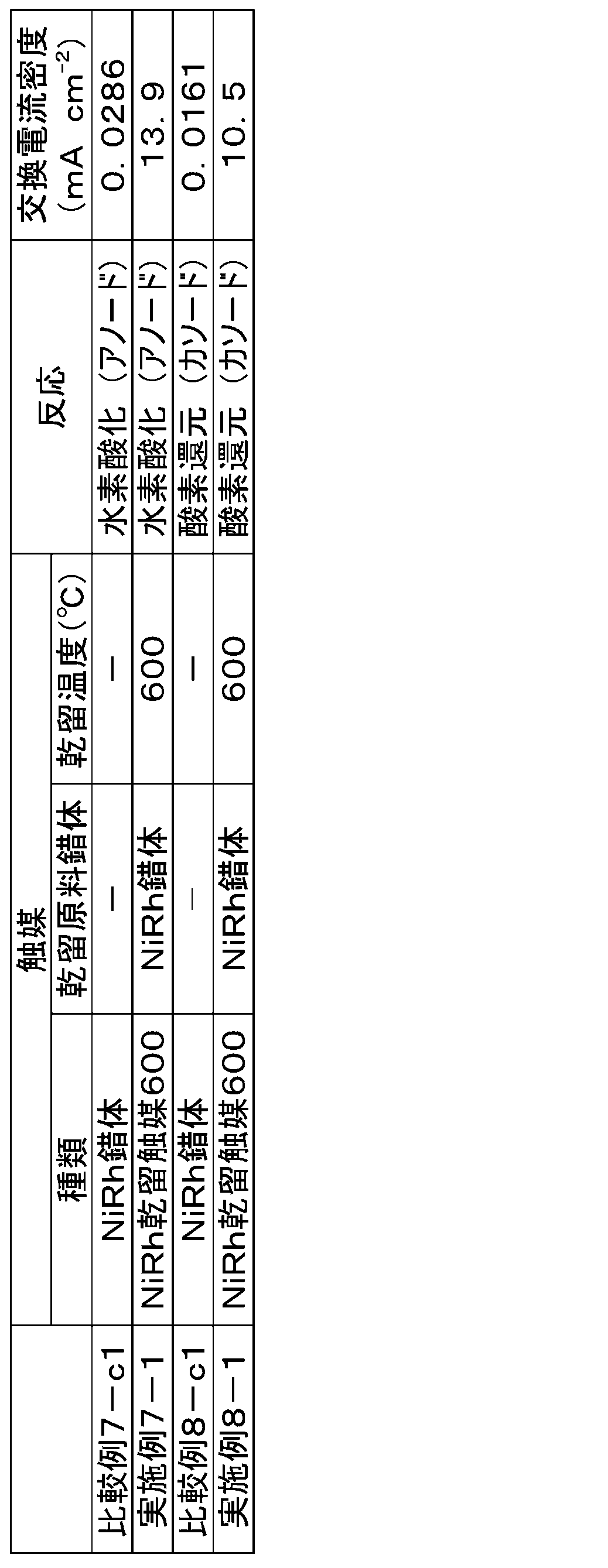
Claims (17)
- 第1の遷移金属M1および第2の遷移金属M2を構成元素として含む触媒成分と導電性材料とを含む電極触媒であって、
第1の遷移金属M1、第2の遷移金属M2、炭素、水素、窒素および硫黄を構成元素として含み、かつ、水素の含有量および窒素の含有量がともに1重量%未満である粒子であり、
当該粒子の表面に第1の遷移金属M1の硫化物と第2の遷移金属M2が観測される電極触媒。 - 第1の遷移金属M1および第2の遷移金属M2を構成元素として含む触媒成分と導電性材料とを含む電極触媒であって、
第1の遷移金属M1、第2の遷移金属M2、炭素、水素、窒素および硫黄を構成元素として含み、かつ、水素の含有量および窒素の含有量がともに1重量%未満である粒子であり、
当該粒子の表面に第1の遷移金属M1の硫化物と金属態の第2の遷移金属M2が観測される電極触媒。 - 前記第1の遷移金属M1が、Ni、Mn、Fe、Co、Cu、およびZnからなる群より選ばれるいずれかであり、
前記第2の遷移金属M2が、Ru、Rh、Pd、Ag、Ir、およびPtからなる群より選ばれるいずれかである、請求項1または2に記載の電極触媒。 - 前記第1の遷移金属M1が、Niであり、
前記第2の遷移金属M2が、Ru、Rh、およびIrからなる群より選ばれるいずれかである、請求項1または2に記載の電極触媒。 - 前記粒子の表面に、さらに第2の遷移金属M2の硫化物が観測される、請求項1~4のいずれか1項に記載の電極触媒。
- 前記導電性材料が、アセチレンブラック、バルカン、ケッチェンブラック、ブラックパール、黒鉛化アセチレンブラック、黒鉛化バルカン、黒鉛化ケッチェンブラック、黒鉛化ブラックパール、カーボンナノチューブ、カーボンナノファイバー、カーボンナノホーン、およびカーボンフィブリルからなる群より選ばれるいずれかである、請求項1~5のいずれか1項に記載の電極触媒。
- 下記工程1aおよび2aを含む、電極触媒の製造方法:
工程1a:下記式(1)

工程2a:前記工程1aで得られた混合物を乾留させる工程。 - 前記工程2aが、真空下かつ100~800℃の温度で行われる、請求項7に記載の製造方法。
- 前記温度が300~800℃の範囲内である、請求項8に記載の製造方法。
- 前記真空が、真空度10~20Paである、請求項8または9に記載の製造方法。
- 前記導電性材料が、アセチレンブラック、バルカン、ケッチェンブラック、ブラックパール、黒鉛化アセチレンブラック、黒鉛化バルカン、黒鉛化ケッチェンブラック、黒鉛化ブラックパール、カーボンナノチューブ、カーボンナノファイバー、カーボンナノホーン、およびカーボンフィブリルからなる群より選ばれるいずれかである、請求項7~10のいずれか1項に記載の製造方法。
- 請求項10に記載の製造方法で得られた電極触媒。
- 請求項1~6,12のいずれか1項に記載の電極触媒を含む燃料電池用電極。
- カソードと、アノードと、前記カソードと前記アノードとの間に配置されたプロトン伝導膜とを有する膜電極接合体であって、カソードとアノードとからなる群より選ばれるいずれか1以上が請求項13に記載の燃料電池用電極である膜電極接合体。
- 請求項14に記載の膜電極接合体を備えることを特徴とする燃料電池。
- 請求項13に記載の燃料電池用電極を、カソード、アノード、または、カソードとアノードとの両方として有する燃料電池。
- 水素-酸素型燃料電池である請求項15または16に記載の燃料電池。
Applications Claiming Priority (2)
| Application Number | Priority Date | Filing Date | Title |
|---|---|---|---|
| JP2020145079A JP2023171977A (ja) | 2020-08-28 | 2020-08-28 | 電極触媒およびその製造方法、並びに燃料電池 |
| JP2020-145079 | 2020-08-28 |
Publications (1)
| Publication Number | Publication Date |
|---|---|
| WO2022045290A1 true WO2022045290A1 (ja) | 2022-03-03 |
Family
ID=80353435
Family Applications (1)
| Application Number | Title | Priority Date | Filing Date |
|---|---|---|---|
| PCT/JP2021/031498 Ceased WO2022045290A1 (ja) | 2020-08-28 | 2021-08-27 | 電極触媒およびその製造方法、並びに燃料電池 |
Country Status (2)
| Country | Link |
|---|---|
| JP (1) | JP2023171977A (ja) |
| WO (1) | WO2022045290A1 (ja) |
Citations (2)
| Publication number | Priority date | Publication date | Assignee | Title |
|---|---|---|---|---|
| JP2002329500A (ja) * | 2001-03-02 | 2002-11-15 | National Institute Of Advanced Industrial & Technology | 低温型燃料電池の燃料極用電極触媒 |
| WO2006083029A1 (ja) * | 2005-02-03 | 2006-08-10 | Toyota Jidosha Kabushiki Kaisha | 触媒材料およびその製造方法 |
-
2020
- 2020-08-28 JP JP2020145079A patent/JP2023171977A/ja active Pending
-
2021
- 2021-08-27 WO PCT/JP2021/031498 patent/WO2022045290A1/ja not_active Ceased
Patent Citations (2)
| Publication number | Priority date | Publication date | Assignee | Title |
|---|---|---|---|---|
| JP2002329500A (ja) * | 2001-03-02 | 2002-11-15 | National Institute Of Advanced Industrial & Technology | 低温型燃料電池の燃料極用電極触媒 |
| WO2006083029A1 (ja) * | 2005-02-03 | 2006-08-10 | Toyota Jidosha Kabushiki Kaisha | 触媒材料およびその製造方法 |
Also Published As
| Publication number | Publication date |
|---|---|
| JP2023171977A (ja) | 2023-12-06 |
Similar Documents
| Publication | Publication Date | Title |
|---|---|---|
| Li et al. | Boosting oxygen reduction activity of Fe-NC by partial copper substitution to iron in Al-air batteries | |
| Liu et al. | The solid‐phase synthesis of an Fe‐N‐C electrocatalyst for high‐power proton‐exchange membrane fuel cells | |
| Park et al. | Architecting the high‐entropy oxides on 2D MXene nanosheets by rapid microwave‐heating strategy with robust photoelectrochemical oxygen evolution performance | |
| Bhowmick et al. | Improved performance of microbial fuel cell by using conductive ink printed cathode containing Co3O4 or Fe3O4 | |
| KR100745736B1 (ko) | 카본나노튜브, 이를 포함한 담지 촉매 및 상기 담지 촉매를이용한 연료전지 | |
| Cheng et al. | A template-free method to synthesis high density iron single atoms anchored on carbon nanotubes for high temperature polymer electrolyte membrane fuel cells | |
| Berghian-Grosan et al. | Platinum nanoparticles coated by graphene layers: A low-metal loading catalyst for methanol oxidation in alkaline media | |
| KR101624641B1 (ko) | 연료전지용 전극 촉매, 그 제조방법, 및 이 전극 촉매를 이용한 막 전극 접합체와 연료전지 | |
| Huang et al. | Microwave synthesis and electrochemical performance of a PtPb alloy catalyst for methanol and formic acid oxidation | |
| Flórez-Montaño et al. | Ni@ Pt nanodisks with low Pt content supported on reduced graphene oxide for methanol electrooxidation in alkaline media | |
| Na et al. | Boosting electrocatalytic activity with the formation of abundant heterointerfaces and N, S dual-doped carbon nanotube for rechargeable Zn-air battery | |
| Yang et al. | Covalent organic polymers derived carbon incorporated with cobalt oxides as a robust oxygen reduction reaction catalyst for fuel cells | |
| JP2007207662A (ja) | 燃料電池用電極触媒及びその製造方法並びに該触媒を用いた燃料電池 | |
| Qiao et al. | Pyrolytic carbon‐coated Cu‐Fe alloy nanoparticles with high catalytic performance for oxygen electroreduction | |
| US20070078052A1 (en) | Methanol tolerant catalyst material | |
| Heydari et al. | Fabrication of electrocatalyst based on nitrogen doped graphene as highly efficient and durable support for using in polymer electrolyte fuel cell | |
| WO2017208742A1 (ja) | 触媒担持用カーボン及びその製造方法 | |
| Milikić et al. | A Pt/MnV2O6 nanocomposite for the borohydride oxidation reaction | |
| Jiang et al. | Electrocatalytic activity of metalloporphyrins grown in situ on graphene sheets toward oxygen reduction reaction in an alkaline medium | |
| Kakati et al. | Hydrothermal synthesis of PtRu on CNT/SnO2 composite as anode catalyst for methanol oxidation fuel cell | |
| JP2016508439A (ja) | 触媒 | |
| Qu et al. | Mild synthesis of layer-by-layer SnO2 nanosheet/Pt/graphene composites as catalysts for ethanol electro-oxidation | |
| Cheng et al. | The influence of a new fabrication procedure on the catalytic activity of ruthenium–selenium catalysts | |
| Huynh et al. | Heat treatment for enhancing Ir-based catalysts enclosed in a carbon layer for electrochemical oxygen evolution reaction | |
| Etesami et al. | Solvent-free synthesis of FeCo alloy nanoparticle-embedded nitrogen-doped carbon nanotubes for oxygen reduction in zinc-air batteries |
Legal Events
| Date | Code | Title | Description |
|---|---|---|---|
| 121 | Ep: the epo has been informed by wipo that ep was designated in this application |
Ref document number: 21861711 Country of ref document: EP Kind code of ref document: A1 |
|
| NENP | Non-entry into the national phase |
Ref country code: DE |
|
| 122 | Ep: pct application non-entry in european phase |
Ref document number: 21861711 Country of ref document: EP Kind code of ref document: A1 |
|
| NENP | Non-entry into the national phase |
Ref country code: JP |