WO2022044751A1 - プログラム、処理装置、基地局装置 - Google Patents
プログラム、処理装置、基地局装置 Download PDFInfo
- Publication number
- WO2022044751A1 WO2022044751A1 PCT/JP2021/029027 JP2021029027W WO2022044751A1 WO 2022044751 A1 WO2022044751 A1 WO 2022044751A1 JP 2021029027 W JP2021029027 W JP 2021029027W WO 2022044751 A1 WO2022044751 A1 WO 2022044751A1
- Authority
- WO
- WIPO (PCT)
- Prior art keywords
- base station
- communication system
- wireless communication
- restricted area
- center
- Prior art date
- Legal status (The legal status is an assumption and is not a legal conclusion. Google has not performed a legal analysis and makes no representation as to the accuracy of the status listed.)
- Ceased
Links
Images



Classifications
-
- H—ELECTRICITY
- H04—ELECTRIC COMMUNICATION TECHNIQUE
- H04W—WIRELESS COMMUNICATION NETWORKS
- H04W16/00—Network planning, e.g. coverage or traffic planning tools; Network deployment, e.g. resource partitioning or cells structures
- H04W16/18—Network planning tools
-
- H—ELECTRICITY
- H04—ELECTRIC COMMUNICATION TECHNIQUE
- H04W—WIRELESS COMMUNICATION NETWORKS
- H04W16/00—Network planning, e.g. coverage or traffic planning tools; Network deployment, e.g. resource partitioning or cells structures
- H04W16/24—Cell structures
- H04W16/28—Cell structures using beam steering
-
- H—ELECTRICITY
- H04—ELECTRIC COMMUNICATION TECHNIQUE
- H04B—TRANSMISSION
- H04B7/00—Radio transmission systems, i.e. using radiation field
- H04B7/02—Diversity systems; Multi-antenna system, i.e. transmission or reception using multiple antennas
- H04B7/04—Diversity systems; Multi-antenna system, i.e. transmission or reception using multiple antennas using two or more spaced independent antennas
- H04B7/06—Diversity systems; Multi-antenna system, i.e. transmission or reception using multiple antennas using two or more spaced independent antennas at the transmitting station
- H04B7/0613—Diversity systems; Multi-antenna system, i.e. transmission or reception using multiple antennas using two or more spaced independent antennas at the transmitting station using simultaneous transmission
- H04B7/0615—Diversity systems; Multi-antenna system, i.e. transmission or reception using multiple antennas using two or more spaced independent antennas at the transmitting station using simultaneous transmission of weighted versions of same signal
- H04B7/0617—Diversity systems; Multi-antenna system, i.e. transmission or reception using multiple antennas using two or more spaced independent antennas at the transmitting station using simultaneous transmission of weighted versions of same signal for beam forming
-
- H—ELECTRICITY
- H04—ELECTRIC COMMUNICATION TECHNIQUE
- H04W—WIRELESS COMMUNICATION NETWORKS
- H04W16/00—Network planning, e.g. coverage or traffic planning tools; Network deployment, e.g. resource partitioning or cells structures
- H04W16/14—Spectrum sharing arrangements between different networks
-
- H—ELECTRICITY
- H04—ELECTRIC COMMUNICATION TECHNIQUE
- H04W—WIRELESS COMMUNICATION NETWORKS
- H04W16/00—Network planning, e.g. coverage or traffic planning tools; Network deployment, e.g. resource partitioning or cells structures
- H04W16/24—Cell structures
- H04W16/30—Special cell shapes, e.g. doughnuts or ring cells
Definitions
- the present invention relates to a processing technique, and particularly to a program, a processing device, and a base station device for determining parameters when a base station device is installed.
- Non-Patent Document 1 In order for a mobile communication operator to obtain a license for a 5G system, it is essential to adjust interference with existing systems that use the same frequency band. For example, satellite communication systems have already been assigned to the 3.7 GHz band and 28 GHz band used in 5G systems. In order to reduce the interference from the base station equipment of the 5G system to the communication equipment of the existing satellite communication system, the direction of the electrical beam of the base station equipment is restricted so as not to be directed to the existing communication equipment (for example). , See Non-Patent Document 1).
- Interference from each base station device is accumulated in order to guarantee protection for the existing system and for the mobile communication operator to obtain a license for the 5G system.
- interference is calculated using the maximum antenna pattern of the base station appliance.
- the maximum antenna pattern has the maximum antenna gain in each direction for all beams.
- the present invention has been made in view of these problems, and an object of the present invention is to provide a technique for suppressing a decrease in the number of installed base station devices while reducing interference with an existing system.
- the program of a certain aspect of the present invention is included in the first wireless communication system among the first wireless communication system and the second wireless communication system that use the same frequency band and are different from each other. It is a program for determining the conditions for installing each of the plurality of base station devices, and is included in the second wireless communication system when a signal is transmitted from each of the plurality of base station devices while changing the azimuth angle.
- Another aspect of the present invention is a processing device.
- This device is for installing each of a plurality of base station devices included in the first wireless communication system among the first wireless communication system and the second wireless communication system that use the same frequency band and are different from each other.
- It is a processing device that determines the conditions, and when a signal is transmitted from each of a plurality of base station devices while changing the azimuth angle, the interference power of the signal received by the target station included in the second wireless communication system is determined.
- the acquisition unit acquired for each combination of the base station device and the azimuth angle, and the range of the azimuth angle at which the ratio of the magnitude of the interference power larger than the first threshold value is larger than the second threshold value are specified as the restricted area. It includes a specific unit and a determination unit that determines the direction of the center of each beam of the plurality of base station devices so that the center of each beam of the plurality of base station devices is not included in the restricted area.
- Yet another aspect of the present invention is a base station device.
- This device includes a receiving unit that receives information and a setting unit that sets the direction of the center of the beam based on the information received by the receiving unit.
- the present invention it is possible to suppress the reduction in the number of base station devices installed while reducing the interference with the existing system.
- interference from the base station equipment to the existing system is evaluated as the worst case for the 5G system.
- Interference from the base station equipment to the existing system corresponds to interference from the satellite communication system to the space station at 28 GHz.
- the transmit power is set to the maximum transmit power and the antenna pattern is set to the maximum antenna pattern. Based on the evaluation results under such conditions, it is possible to deploy the base station device in a range where the added value of the interference becomes smaller than the threshold value of the existing system.
- Non-Patent Document 1 the electrical beam is restricted. Therefore, the three radio units in one base station device are freely arranged, but the use of the beam is restricted, which causes a decrease in coverage and capacity.
- the limitation of coexistence with the existing system is relaxed by limiting the direction of each of the plurality of base station devices in common. Since each direction of the plurality of base station devices is restricted in common, it is not necessary to restrict the electrical beam which deteriorates the performance of 5G in terms of coverage and capacity. Therefore, the number of base station devices deployed under the constraint of interference is increased.
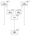
- FIG. 1 shows the configuration of the first wireless communication system 10 and the second wireless communication system 20.
- the first wireless communication system 10 includes a first base station device 100a and a second base station device 100b collectively referred to as a base station device 100, a first terminal device 150a and a second terminal device 150b collectively referred to as a terminal device 150.
- the second radio communication system 20 includes a space station 200 and an earth station 250.
- the number of base station devices 100 and terminal devices 150 included in the first wireless communication system 10 is not limited to "2".
- the first wireless communication system 10 is, for example, a 5G communication system and corresponds to the above-mentioned 5G system.
- the 28 GHz band is used, and communication between the base station device 100 and the terminal device 150 is executed.
- the second wireless communication system 20 is, for example, a satellite communication system, and corresponds to the above-mentioned existing system.
- the 28 GHz band is used, and communication from the earth station 250 to the space station 200 is executed.
- a frequency band other than the 28 GHz band may be used for communication from the space station 200 to the earth station 250.
- the first wireless communication system 10 and the second wireless communication system 20 use the same frequency band and are different systems from each other.
- a process for installing a plurality of base station devices 100 in a situation where communication between the space station 200 and the earth station 250 in the second wireless communication system 20 is being executed will be described.
- the interference power received by the space station 200 from the base station device 100 must be smaller than the allowable value specified in the second radio communication system 20.
- the space station 200 is sometimes called a target station.
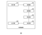
- FIG. 2 shows the configuration of the processing device 300.
- the processing device 300 includes a reception unit 310, a processing unit 320, an acquisition unit 330, a specific unit 340, a determination unit 350, and an output unit 360.
- the processing device 300 is a computer that executes an application program for determining conditions for installing each of the plurality of base station devices 100.
- the reception unit 310 has an interface operated by the user, and from the user via the interface, the position information of each of the plurality of base station devices 100 included in the first wireless communication system 10 (hereinafter, “first position information”). ”) And the position information of the space station 200 included in the second wireless communication system 20 (hereinafter referred to as“ second position information ”).
- first position information the position information of each of the plurality of base station devices 100 included in the first wireless communication system 10
- second position information the position information of the space station 200 included in the second wireless communication system 20
- the second position information indicates the position information of the geostationary satellite.
- the reception unit 310 outputs a plurality of first position information and the second position information to the processing unit 320.
- the processing unit 320 is a propagation path simulator, and executes, for example, a ray trace simulation.
- the processing unit 320 derives the received power when the signals transmitted by each of the plurality of base station devices 100 are received by the space station 200 as interference power for each base station device 100 by ray tracing simulation.
- simulation parameters such as transmission power in the base station apparatus 100 are set so as to be compatible with the 5G communication system.
- the azimuth angle of each base station device 100 with respect to the antenna is "0 degrees” for true north, “90 degrees” for true east, “180 degrees” for true south, and “270 degrees” for true west. It is specified clockwise so that it is “degree”.
- the processing unit 320 adjusts the azimuth angles of the plurality of base station devices 100 to "0 degrees” and then transmits a signal in the direction of the azimuth angles, the processing unit 320 transfers the interference power in the space station 200 to each base station device 100. Derived to. Following this, the processing unit 320 changes the azimuth angles of the plurality of base station devices 100 to derive the interference power in the space station 200 for each base station device 100.
- the azimuth angles of the base station devices 100 are set to the same value. That is, when the processing unit 320 transmits a signal while changing the azimuth angles of the plurality of base station devices 100 by the same value, the interference power of the signal received by the space station 200 is set with the base station device 100. Derived for each azimuth combination.
- the acquisition unit 330 acquires the result of the ray trace simulation in the processing unit 320. More specifically, the acquisition unit 330 acquires the interference power derived for each combination of the base station device 100 and the azimuth angle.
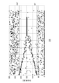
- FIG. 3 shows the distribution of the interference power with respect to the azimuth angle acquired by the acquisition unit 330.
- the vertical axis shows the azimuth angle [degrees].
- black circles indicate interference powers of ⁇ 230 dBm / MHz or less
- cross marks indicate interference powers of ⁇ 180 dBm / MHz or more.
- the specific unit 340 receives the distribution shown in FIG. 3 from the acquisition unit 330.
- the interference from the base station device 100 with respect to the space station 200 in geosynchronous orbit falls into two categories: interference power of -230 dBm / MHz or less and interference power of -180 dBm / MHz or more. being classified.
- the two categories do not consider the elevation angles of the plurality of base station devices 100.
- the identification unit 340 specifies the range of the azimuth angle including the interference power of ⁇ 180 dBm / MHz or more from the distribution in FIG.
- a range of 80 to 258 degrees is specified.
- the specified range is referred to as a "restricted area”.
- FIG. 4 shows a restricted area 400 specified by the specific unit 340.
- the azimuth is specified to be clockwise.
- the range of the azimuth angle of 80 degrees to 258 degrees is defined as the restricted area 400.
- the interference power in the space station 200 may exceed the allowable value or is relatively small.
- ⁇ 180 dBm / MHz may be referred to as a threshold value. Further, the threshold value is not limited to ⁇ 180 dBm / MHz. As a result, the plurality of base station devices 100 having an azimuth angle of 80 degrees to 258 degrees are not deployed.
- the determination unit 350 determines the orientation of the plurality of base station devices 100 based on the restricted area 400 specified by the specific unit 340.
- the antenna provided in each base station device 100 is a plurality of sector antennas.
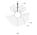
- FIG. 5 shows the configuration of the sector antenna 140 in the base station device 100.
- the azimuths in the figure are shown as before.
- the antenna includes a first sector antenna 140a, a second sector antenna 140b, and a third sector antenna 140c, which are collectively referred to as a sector antenna 140.
- the number of sector antennas 140 included in the antenna is not limited to "3".
- the center direction of the beam of the first sector antenna 140a is oriented at an azimuth angle of "0 degrees”
- the center direction of the beam of the second sector antenna 140b is directed at an azimuth angle of "120 degrees”
- the center direction of the beam of the third sector antenna 140c is directed. Faces the azimuth "180 degrees”.
- the beam width of the first sector antenna 140a has an azimuth angle of "300 to 60 degrees”
- the beam width of the second sector antenna 140b has an azimuth angle of "60 degrees to 180 degrees”
- the beam width of the third sector antenna 140c The beam width is "180 to 300 degrees”. That is, the center directions of the beams of each sector antenna 140 have different azimuth angles, and the beam width is a width of "-60 degrees” to "+60 degrees" with respect to the center direction of the beam.
- the determination unit 350 determines the direction of the center of each beam of the plurality of base station devices 100 so that the center of each beam of the plurality of base station devices 100 is not included in the restricted area 400.
- FIG. 6 shows the center direction of the beam determined by the determination unit 350.
- the restricted area 400 is shown in the same manner as in FIG. Here, the first sector antenna 140a facing "0 degrees", which is an azimuth angle other than 80 degrees to 258 degrees in the restricted area 400, is selected. That is, the determination unit 350 selects the sector antenna 140 whose beam center does not face the restricted area 400.
- the space station is determined by determining the direction of the center of each beam of the plurality of base station devices 100 so as not to be included in the restricted area 400, that is, by limiting the azimuth angle of the base station device 100.
- the interference given to 200 is reduced.
- the beam of the base station device 100 can be used without limitation in the sector of the base station device 100. As a result, the number of base station devices 100 that can be deployed increases.
- the determination unit 350 may determine the position where each of the plurality of base station devices 100 is installed.
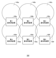
- FIG. 7 shows the arrangement of the base station apparatus 100 determined by the determination unit 350.
- the first base station apparatus 100a to the sixth base station apparatus 100f are shown.
- the first sector antenna 140a is selected in each base station device 100.
- the first base station apparatus 100a forms the first communicable area 142a
- the second base station apparatus 100b forms the second communicable area 142b
- the sixth base station device 100f forms the sixth communicable area 142f.
- the first communicable area 142a to the sixth communicable area 142f are collectively referred to as the communicable area 142.
- the communicable area 142 is an area communicable with the base station device 100, which is an area covered by the beam of the base station device 100.
- the second communicable area 142b is formed in the direction of the azimuth angle "0 degree” from the second base station device 100b.
- the second communicable area 142b does not cover the directions of the azimuth angles "90 degrees”, “180 degrees”, and "270 degrees” from the second base station device 100b.
- the fifth base station In order to cover the direction of the azimuth angle "180 degrees” from the second base station apparatus 100b not covered by the second communicable area 142b, the fifth base station in the direction of the azimuth angle "180 degrees” from the second base station apparatus 100b.
- the device 100e is arranged. Since the fifth base station device 100e faces the same azimuth as the second base station device 100b, the direction of the azimuth angle "180 degrees” from the second base station device 100b is covered by the fifth communicable area 142e.
- the first base station station In order to cover the direction of the azimuth angle "270 degrees” from the second base station apparatus 100b not covered by the second communicable area 142b, the first base station station in the direction of the azimuth angle "270 degrees” from the second base station apparatus 100b.
- the device 100a is arranged, and the fourth base station device 100d is arranged in the direction of the azimuth angle "270 degrees” from the fifth base station device 100e.
- the relative positional relationship between the first base station device 100a and the fourth base station device 100d is the same as the relative positional relationship between the second base station device 100b and the fifth base station device 100e.
- the direction of the azimuth angle "270 degrees" from the second base station device 100b is the first communicable area. It is covered by 142a and the fourth communicable area 142d.
- the third base station In order to cover the direction of the azimuth angle "90 degrees” from the second base station apparatus 100b not covered by the second communicable area 142b, the third base station in the direction of the azimuth angle "90 degrees” from the second base station apparatus 100b.
- the device 100c is arranged, and the sixth base station device 100f is arranged in the direction of the azimuth angle "90 degrees” from the fifth base station device 100e.
- the relative positional relationship between the third base station device 100c and the sixth base station device 100f is the same as the relative positional relationship between the second base station device 100b and the fifth base station device 100e.
- the direction of the azimuth angle "90 degrees" from the second base station device 100b is the third communicable area. It is covered by 142c and the sixth communicable area 142f. That is, the other base station apparatus 100 is arranged so that the area not covered by one base station apparatus 100 is covered by the communicable area 142 formed by the other base station apparatus 100.
- the output unit 360 outputs information regarding the direction of the center of the beam determined by the determination unit 350 and information regarding the arrangement of the base station device 100.
- the output may be displayed on a monitor or sent as electronic data.
- the output unit 360 When the output unit 360 is connected to each base station device 100 via a network (not shown), the output unit 360 provides information regarding the direction of the center of the beam determined by the determination unit 350 to each base station device. It may be transmitted to 100.
- This configuration can be realized by a CPU (Central Processing Unit), memory, or other LSI (Large Scale Integration) of any computer in terms of hardware, and by a program loaded in memory in terms of software.
- CPU Central Processing Unit
- LSI Large Scale Integration
- FIG. 8 shows the configuration of the base station device 100.
- the base station device 100 includes a wired communication unit 110, a setting unit 120, a wireless communication unit 130, and a sector antenna 140.
- the wired communication unit 110 is connected to a network (not shown), and executes communication with a core network composed of routers and servers, or with other base station devices 100, via the network. ..
- the receiving unit 112 of the wired communication unit 110 receives the information from the processing device 300.
- the setting unit 120 sets the direction of the center of the beam in the sector antenna 140 based on the information received by the receiving unit 112.
- the wireless communication unit 130 uses the sector antenna 140 whose center direction of the beam is set by the setting unit 120 to perform communication with the terminal device 150 of FIG. 1. Since known techniques may be used for the wired communication unit 110 and the wireless communication unit 130, the description thereof will be omitted here.
- This configuration can be realized by a CPU (Central Processing Unit), memory, or other LSI (Large Scale Integration) of any computer in terms of hardware, and by a program loaded in memory in terms of software.
- CPU Central Processing Unit
- LSI Large Scale Integration
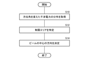
- FIG. 9 is a flowchart showing a determination procedure by the processing device 300.
- the acquisition unit 330 acquires the distribution of the interference power with different azimuth angles (S10).
- the specifying unit 340 specifies the restricted area 400 based on the distribution of the interference power (S12).
- the determination unit 350 determines the direction of the center of the beam (S14).
- the range of the azimuth angle including the interference power above the threshold value is specified as the restricted area, and the center of each beam of the plurality of base station devices is not included in the restricted area. Since the direction of the center of each beam of the base station device is determined, the interference with the space station can be reduced. Further, since the interference with the space station is reduced, it is possible to suppress the reduction in the number of base station devices installed. Further, since the reduction in the number of base station devices installed is suppressed, the installation of base station devices can be expanded. In addition, since the beam is not restricted, it is possible to suppress a decrease in coverage and capacity.
- the processing can be simplified. Further, since the position where each of the plurality of base station devices is installed is also determined, it is possible to suppress a decrease in the area covered by the plurality of base station devices. Further, since the information regarding the direction of the determined beam center is output, the information regarding the determined beam center direction can be used. Further, since the direction of the center of the beam is set based on the information received from the processing device, the center of the beam can be directed in the direction in which the interference with the space station is reduced.
- the base station device 100 in this embodiment includes a plurality of sector antennas 140.
- the present invention is not limited to this, and for example, the base station apparatus 100 may include one sector antenna 140 that can be rotated in a horizontal plane so that the azimuth angle can be changed.
- the sector antenna 140 is directed in the direction determined by the determination unit 350. According to this modification, the degree of freedom of configuration can be improved.
- the satellite communication system is already arranged as the second wireless communication system 20.
- the present invention is not limited to this, and for example, another satellite communication system different from the second wireless communication system 20 may already be arranged as the third wireless communication system.
- the third wireless communication system uses the same frequency band as the first wireless communication system 10 and the second wireless communication system 20.
- the space station 200 included in the second wireless communication system 20 is referred to as a "second space station (second target station)”
- the restricted area 400 for the second wireless communication system 20 is referred to as a "second restricted area”. .
- the space station included in the third wireless communication system is called a "third space station (third target station)"
- the restricted area for the third wireless communication system is called a "third restricted area”.
- the processing unit 320, the acquisition unit 330, and the specific unit 340 perform the same processing as before for the third space station of the third radio communication system, so that the interference power in the third space station can be calculated.
- the range of the azimuth angle including the interference power equal to or higher than the threshold value is specified as the third restricted area.
- the specific unit 340 derives a comprehensive restricted area by combining the second restricted area and the third restricted area. For example, the total restricted area is derived by adding the range of the azimuth angle in the second restricted area and the range of the azimuth angle in the third control area. If the second restricted area is in the range of 80 to 258 degrees and the third restricted area is in the range of 10 to 230 degrees, the total restricted area is in the range of 10 to 258 degrees.
- the comprehensive restricted area may be derived based on the overlapping portion of the azimuth range in the second restricted area and the azimuth range in the third control area. If the second restricted area is in the range of 80 to 258 degrees and the third restricted area is in the range of 10 to 230 degrees, the total restricted area is in the range of 80 to 230 degrees.
- the determination unit 350 determines that the center of each beam of the plurality of base station devices 100 is not included in the total restricted area. According to this modification, the degree of freedom of configuration can be improved.
- the present invention it is possible to suppress the reduction in the number of base station devices installed while reducing the interference with the existing system.
Landscapes
- Engineering & Computer Science (AREA)
- Computer Networks & Wireless Communication (AREA)
- Signal Processing (AREA)
- Mobile Radio Communication Systems (AREA)
Abstract
Description
Claims (7)
- 同一の周波数帯を使用し、かつ互いに異なった第1無線通信システムと第2無線通信システムのうち、前記第1無線通信システムに含まれる複数の基地局装置のそれぞれを設置するための条件を決定するプログラムであって、
前記複数の基地局装置のそれぞれから方位角を変えながら信号を送信した場合に、前記第2無線通信システムに含まれる対象局に受信される信号の干渉電力を、基地局装置と方位角の組合せ毎に取得するステップと、
しきい値以上の干渉電力が含まれる方位角の範囲を制限エリアとして特定するステップと、
前記複数の基地局装置のそれぞれのビームの中心を前記制限エリアに含めないように、前記複数の基地局装置のそれぞれのビームの中心の方向を決定するステップとをコンピュータに実行させるためのプログラム。 - 前記複数の基地局装置のそれぞれは複数のセクタアンテナを備え、
前記ビームの中心の方向を決定するステップは、前記制限エリアにビームの中心が向かないセクタアンテナを選択する請求項1に記載のプログラム。 - 前記ビームの中心の方向を決定するステップは、前記複数の基地局装置のそれぞれを設置する位置も決定する請求項1または2に記載のプログラム。
- 前記第1無線通信システムと前記第2無線通信システムと同一の周波数帯を使用する第3無線通信システムが存在し、
前記第2無線通信システムに含まれる対象局を第2対象局と呼び、前記第2無線通信システムに対する制限エリアを第2制限エリアと呼ぶ場合、前記第3無線通信システムに含まれる対象局は第3対象局と呼ばれ、前記第3無線通信システムに対する制限エリアは第3制限エリアと呼ばれ、
前記複数の基地局装置のそれぞれから方位角を変えながら信号を送信した場合に、前記第3対象局に受信される信号の干渉電力を、基地局装置と方位角の組合せ毎に取得するステップと、
前記第3対象局における干渉電力のうち、しきい値以上の干渉電力が含まれる方位角の範囲を前記第3制限エリアとして特定するステップと、
前記第2制限エリアと前記第3制限エリアとを組み合わせることによって、総合制限エリアを導出するステップとをさらに備え、
前記ビームの中心の方向を決定するステップは、前記複数の基地局装置のそれぞれのビームの中心を前記総合制限エリアに含めないようにする請求項1から3のいずれかに記載のプログラム。 - 同一の周波数帯を使用し、かつ互いに異なった第1無線通信システムと第2無線通信システムのうち、前記第1無線通信システムに含まれる複数の基地局装置のそれぞれを設置するための条件を決定する処理装置であって、
前記複数の基地局装置のそれぞれから方位角を変えながら信号を送信した場合に、前記第2無線通信システムに含まれる対象局に受信される信号の干渉電力を、基地局装置と方位角の組合せ毎に取得する取得部と、
しきい値以上の干渉電力が含まれる方位角の範囲を制限エリアとして特定する特定部と、
前記複数の基地局装置のそれぞれのビームの中心を前記制限エリアに含めないように、前記複数の基地局装置のそれぞれのビームの中心の方向を決定する決定部と、
を備える処理装置。 - 前記決定部において決定したビームの中心の方向に関する情報を出力する出力部をさらに備える請求項5に記載の処理装置。
- 請求項6に記載の処理装置からの情報を受信する受信部と、
前記受信部において受信した情報をもとに、ビームの中心の方向を設定する設定部と、
を備える基地局装置。
Priority Applications (2)
| Application Number | Priority Date | Filing Date | Title |
|---|---|---|---|
| US17/799,688 US12432572B2 (en) | 2020-08-26 | 2021-08-04 | Non-transitory computer readable storage medium, processing device, and base station device for determining parameter when base station device is installed |
| JP2022545604A JP7457819B2 (ja) | 2020-08-26 | 2021-08-04 | プログラム、処理装置、基地局装置 |
Applications Claiming Priority (2)
| Application Number | Priority Date | Filing Date | Title |
|---|---|---|---|
| JP2020-142904 | 2020-08-26 | ||
| JP2020142904 | 2020-08-26 |
Publications (1)
| Publication Number | Publication Date |
|---|---|
| WO2022044751A1 true WO2022044751A1 (ja) | 2022-03-03 |
Family
ID=80355070
Family Applications (1)
| Application Number | Title | Priority Date | Filing Date |
|---|---|---|---|
| PCT/JP2021/029027 Ceased WO2022044751A1 (ja) | 2020-08-26 | 2021-08-04 | プログラム、処理装置、基地局装置 |
Country Status (3)
| Country | Link |
|---|---|
| US (1) | US12432572B2 (ja) |
| JP (1) | JP7457819B2 (ja) |
| WO (1) | WO2022044751A1 (ja) |
Citations (1)
| Publication number | Priority date | Publication date | Assignee | Title |
|---|---|---|---|---|
| WO2019026375A1 (ja) * | 2017-08-04 | 2019-02-07 | ソニー株式会社 | 制御装置、無線装置、方法及び記録媒体 |
Family Cites Families (5)
| Publication number | Priority date | Publication date | Assignee | Title |
|---|---|---|---|---|
| WO2010061775A1 (ja) * | 2008-11-26 | 2010-06-03 | 京セラ株式会社 | 基地局装置および基地局装置の制御方法 |
| CN106470064B (zh) * | 2015-08-21 | 2021-07-30 | 北京三星通信技术研究有限公司 | 发送分集方法及设备 |
| DE102019002516B4 (de) * | 2019-04-07 | 2025-01-30 | Androtec Gmbh | Messanordnung und Verfahren zur optischen oder quasioptischen Positionsbestimmung |
| WO2020230659A1 (ja) * | 2019-05-15 | 2020-11-19 | ソニー株式会社 | 情報処理装置、情報処理方法、及び通信装置 |
| US11019506B2 (en) * | 2019-06-25 | 2021-05-25 | Commscope Technologies Llc | Multi-beam base station antennas having wideband radiating elements |
-
2021
- 2021-08-04 WO PCT/JP2021/029027 patent/WO2022044751A1/ja not_active Ceased
- 2021-08-04 US US17/799,688 patent/US12432572B2/en active Active
- 2021-08-04 JP JP2022545604A patent/JP7457819B2/ja active Active
Patent Citations (1)
| Publication number | Priority date | Publication date | Assignee | Title |
|---|---|---|---|---|
| WO2019026375A1 (ja) * | 2017-08-04 | 2019-02-07 | ソニー株式会社 | 制御装置、無線装置、方法及び記録媒体 |
Non-Patent Citations (1)
| Title |
|---|
| KIM SEUNGMO; VISOTSKY EUGENE; MOORUT PRAKASH; BECHTA KAMIL; GHOSH AMITAVA; DIETRICH CARL: "Coexistence of 5G With the Incumbents in the 28 and 70 GHz Bands", IEEE JOURNAL ON SELECTED AREAS IN COMMUNICATIONS, IEEE SERVICE CENTER, PISCATAWAY., US, vol. 35, no. 6, 1 June 2017 (2017-06-01), US , pages 1254 - 1268, XP011651314, ISSN: 0733-8716, DOI: 10.1109/JSAC.2017.2687238 * |
Also Published As
| Publication number | Publication date |
|---|---|
| US12432572B2 (en) | 2025-09-30 |
| JPWO2022044751A1 (ja) | 2022-03-03 |
| JP7457819B2 (ja) | 2024-03-28 |
| US20230066234A1 (en) | 2023-03-02 |
Similar Documents
| Publication | Publication Date | Title |
|---|---|---|
| US20250253921A1 (en) | Beam selection method and device | |
| US7313391B2 (en) | Modeling of RF point source reference for analysis of wireless signal propagation | |
| US8718541B2 (en) | Techniques for optimal location and configuration of infrastructure relay nodes in wireless networks | |
| Amer et al. | Caching to the sky: Performance analysis of cache-assisted CoMP for cellular-connected UAVs | |
| WO2015161005A1 (en) | System and method for spectrum sharing | |
| US12143827B2 (en) | Communication control apparatus, communication apparatus, and proxy apparatus | |
| KR20180059274A (ko) | Tdma 기반의 무선통신시스템에서 송수신 성능을 향상시키기 위한 빔포밍 안테나의 제어 방법 및 이를 수행하는 무선통신장치 | |
| US20210120433A1 (en) | Communication control device, communication control method, and computer program | |
| CN113573318B (zh) | 频谱使用方法、系统、天线和网络设备 | |
| Kanatas | Coordinates distributions in finite uniformly random networks | |
| US20230114713A1 (en) | Radio frequency (rf)-based ranging and imaging in a wireless communications circuit, particularly for a wireless communications system (wcs) | |
| WO2024008518A1 (en) | Interference-limited transmission from access points | |
| KR102135766B1 (ko) | 시간율을 고려한 이동통신 시스템이 고정 시스템에 미치는 간섭 영향 평가 방법 및 장치 | |
| Cui et al. | Coverage analysis of cellular-connected UAV communications with 3GPP antenna and channel models | |
| WO2022044751A1 (ja) | プログラム、処理装置、基地局装置 | |
| Armeniakos et al. | Angular distance-based performance analysis of mmWave cellular networks | |
| US8326314B1 (en) | Uncoordinated microwave paths in coordinated frequency bands | |
| KR102631820B1 (ko) | Tvws 지향성 안테나를 이용한 원거리 통신 시스템 제어 방법 | |
| US11272377B1 (en) | Site survey for wireless base station placement | |
| Lin et al. | Outage performance for UAV communications under imperfect beam alignment: A stochastic geometry approach | |
| Ma et al. | Optimizing the Tradeoff Between Incumbent Protection and Secondary Transmissions with AFC | |
| US20250150146A1 (en) | Method and radio base station comprising antennas for providing coverage in a cell | |
| US12604220B2 (en) | OTA estimation of an RF parameter of a radio transmitter | |
| Armeniakos et al. | Analysis of Cell Association in mmWave Networks based on Euclidean and Angular Distances | |
| Mikail et al. | Coexistence of 5G and fixed satellite services on MM-wave band |
Legal Events
| Date | Code | Title | Description |
|---|---|---|---|
| 121 | Ep: the epo has been informed by wipo that ep was designated in this application |
Ref document number: 21861179 Country of ref document: EP Kind code of ref document: A1 |
|
| ENP | Entry into the national phase |
Ref document number: 2022545604 Country of ref document: JP Kind code of ref document: A |
|
| NENP | Non-entry into the national phase |
Ref country code: DE |
|
| 122 | Ep: pct application non-entry in european phase |
Ref document number: 21861179 Country of ref document: EP Kind code of ref document: A1 |
|
| WWG | Wipo information: grant in national office |
Ref document number: 17799688 Country of ref document: US |