WO2022044211A1 - 管理装置、管理方法および管理プログラム - Google Patents
管理装置、管理方法および管理プログラム Download PDFInfo
- Publication number
- WO2022044211A1 WO2022044211A1 PCT/JP2020/032398 JP2020032398W WO2022044211A1 WO 2022044211 A1 WO2022044211 A1 WO 2022044211A1 JP 2020032398 W JP2020032398 W JP 2020032398W WO 2022044211 A1 WO2022044211 A1 WO 2022044211A1
- Authority
- WO
- WIPO (PCT)
- Prior art keywords
- measurement
- rule
- information
- node
- management device
- Prior art date
- Legal status (The legal status is an assumption and is not a legal conclusion. Google has not performed a legal analysis and makes no representation as to the accuracy of the status listed.)
- Ceased
Links
Images




Classifications
-
- H—ELECTRICITY
- H04—ELECTRIC COMMUNICATION TECHNIQUE
- H04L—TRANSMISSION OF DIGITAL INFORMATION, e.g. TELEGRAPHIC COMMUNICATION
- H04L47/00—Traffic control in data switching networks
- H04L47/10—Flow control; Congestion control
- H04L47/24—Traffic characterised by specific attributes, e.g. priority or QoS
- H04L47/2425—Traffic characterised by specific attributes, e.g. priority or QoS for supporting services specification, e.g. SLA
-
- H—ELECTRICITY
- H04—ELECTRIC COMMUNICATION TECHNIQUE
- H04W—WIRELESS COMMUNICATION NETWORKS
- H04W28/00—Network traffic management; Network resource management
- H04W28/02—Traffic management, e.g. flow control or congestion control
- H04W28/0268—Traffic management, e.g. flow control or congestion control using specific QoS parameters for wireless networks, e.g. QoS class identifier [QCI] or guaranteed bit rate [GBR]
Definitions
- the present invention relates to a management device, a management method and a management program.
- telemetry information which is measurement information of various measurement items such as traffic amount, delay amount, and jitter related to communication quality
- Patent Document 1 When providing a service based on SLA, it is necessary to measure with fine particle size such as user unit instead of line unit or device unit.
- the processing load of the measurement source node and the notification destination node may increase, or the storage capacity may be compressed.
- the present invention has been made in view of the above, and an object of the present invention is to reduce the number of times of measurement and notification of telemetry information while maintaining the measurement accuracy of telemetry information.
- the management device uses a storage unit for storing operation information, the operation information, and measurement information notified from a node to measure information. It has a judgment unit for determining whether or not it is necessary to change the measurement rule of the above, and an instruction unit for instructing the related node to change the rule when it is determined that the change of the rule is necessary. It is characterized by that.
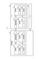
- FIG. 1 is a diagram for explaining an outline of the management device of the present embodiment.
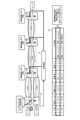
- FIG. 2 is a schematic diagram illustrating a schematic configuration of the management device of the present embodiment.
- FIG. 3 is a diagram illustrating a data structure of operational information.
- FIG. 4 is a diagram for explaining the processing of the management device.
- FIG. 5 is a diagram for explaining the processing of the management device.
- FIG. 6 is a diagram for explaining the processing of the management device.
- FIG. 7 is a diagram for explaining the processing of the management device.
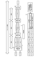
- FIG. 8 is a sequence diagram showing a management processing procedure.
- FIG. 9 is a diagram for explaining the management device of another embodiment.
- FIG. 10 is a diagram showing an example of a computer that executes a management program.
- FIG. 1 is a diagram for explaining an outline of the management device of the present embodiment.
- the management device 10 is interconnected with the nodes 20 (nodes 1 to 5) constituting the communication system 1 to be processed.
- the management device 10 manages operational information such as the network configuration of the communication system 1 and the SLA conditions of each user. Further, the management device 10 acquires measurement information (telemetry information) related to the operating state and communication quality from the node 20 and executes the management process described later.
- the management device 10 monitors the operation status and the communication quality status by using the operation information and the measurement information, and is related when the occurrence of a failure or the change of the status such as the band limitation is detected. Instruct the node 20 to change rules such as measurement items and measurement frequency of measurement information. The instructed node 20 notifies the management device 10 of the measurement information measured by the changed rule. This makes it possible to suppress unnecessary measurement and notification of measurement information while maintaining the measurement accuracy of the measurement information. Therefore, it is possible to reduce the processing load of the node 20 and suppress the pressure on the storage capacity.
- FIG. 2 is a schematic diagram illustrating a schematic configuration of the management device of the present embodiment.
- the management device 10 of the present embodiment is realized by a general-purpose computer or the like, and includes a communication control unit 11, a storage unit 12, and a control unit 13.
- the communication control unit 11 is realized by a NIC (Network Interface Card) or the like, and communicates with an external device such as another network device via a telecommunication line such as a LAN (Local Area Network) or the Internet and the control unit 13. Control.
- the communication control unit 11 controls communication between the node 20 arranged in the communication system 1 and the control unit 13.
- the storage unit 12 is realized by a semiconductor memory element such as a RAM (Random Access Memory) or a flash memory (Flash Memory), or a storage device such as a hard disk or an optical disk.
- the storage unit 12 stores in advance a processing program for operating the management device 10, data used during execution of the processing program, and the like, or temporarily stores each time the processing is performed.
- the storage unit 12 may be configured to communicate with the control unit 13 via the communication control unit 11.
- the storage unit 12 stores the operation information 12a.
- the operation information 12a includes information on services used by each user and information on a network composed of nodes 20. Prior to the management process described later, these pieces of information are acquired from a providing device or the like that manages information and the like related to service provision, and are stored in the storage unit 12.
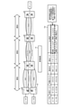
- FIG. 3 is a diagram illustrating the data structure of the operation information.
- the user 1 is using the service A, belongs to the slice 1, and is serviced via the NWs 1, 3, 4 and the nodes 1, 3, 4, 5. It is shown that A is provided and the like. Further, it is shown that the SLA provision condition of the service A is a delay of xxx (ms) or less and a band of yyy (bps) or more.
- the operation information 12a includes past measurement information.
- the measurement information includes information indicating an operating state and communication quality.
- the measurement information is a traffic amount, a delay amount, a jitter, and the like.
- the measurement information is acquired from the node 20 and stored in the storage unit 12 during the execution of the management process.
- the control unit 13 is realized by using a CPU (Central Processing Unit), an NP (Network Processor), an FPGA (Field Programmable Gate Array), or the like, and executes a processing program stored in a memory. As a result, the control unit 13 functions as a determination unit 13a and an instruction unit 13b.
- a CPU Central Processing Unit
- NP Network Processor
- FPGA Field Programmable Gate Array
- the determination unit 13a may be implemented in any of the nodes 20.
- the control unit 13 may include other functional units.
- the control unit 13 may be mounted on any of the nodes 20.
- the determination unit 13a determines whether or not it is necessary to change the measurement rule 22a of the measurement information by using the operation information 12a and the measurement information notified from the node 20. Specifically, the determination unit 13a monitors the operation status and the communication quality status by using the operation information 12a and the measurement information received via the communication control unit (11, 21). Then, the determination unit 13a determines whether or not it is necessary to change the rule 22a set in the node 20 when the occurrence of a failure or the change in the situation such as the band limitation is detected. Then, for example, the determination unit 13a determines that it is necessary to change the rule 22a set in the node 20 when the user or the node 20 is affected by the occurrence of a failure or a change in the situation such as bandwidth limitation. do.
- the measurement information includes information indicating the operation status and communication quality.
- the measurement information is a traffic amount, a delay amount, a jitter, and the like.
- Rule 22a also includes items and frequencies for measurement of measurement information.
- rule 22a includes the frequency of notification of measurement information.
- the instruction unit 13b instructs the related node 20 to change the rule.
- the instruction unit 13b changes the rule 22a so as to reduce the frequency of measurement and notification for the node 20 affected by the occurrence of a failure, band limitation, etc. via the communication control unit (11, 21). Instruct.
- instruction unit 13b may change the rule 22a and instruct the node 20 to apply the changed rule.
- the node 20 is realized by a general-purpose computer or the like, and includes a communication control unit 21, a storage unit 22, and a control unit 23.
- the node 20 measures the measurement information according to a predetermined rule 22a and notifies the management device 10.
- the communication control unit 21 is realized by a NIC (Network Interface Card) or the like, and communicates with an external device such as another network device via a telecommunication line such as a LAN (Local Area Network) or the Internet and the control unit 23. Control.
- the communication control unit 21 controls communication between the management device 10 and other nodes 20 and the control unit 23.
- the storage unit 22 is realized by a semiconductor memory element such as a RAM (Random Access Memory) or a flash memory (Flash Memory), or a storage device such as a hard disk or an optical disk.
- the storage unit 22 stores in advance a processing program for operating the node 20, data used during execution of the processing program, and the like, or temporarily stores each time the processing is performed.
- the storage unit 22 may be configured to communicate with the control unit 23 via the communication control unit 21.
- the storage unit 22 stores the rule 22a.
- rule 22a includes items of measurement information and frequency of measurement. That is, the measurement unit 23a, which will be described later, measures the measurement information according to the rule 22a.
- rule 22a includes the frequency of notification of measurement information.
- the notification unit 23b which will be described later, notifies the management device 10 of the measurement information according to this rule 22a.
- the notification unit 23b which will be described later, updates the changed rule 22a.
- the control unit 23 is realized by using a CPU (Central Processing Unit), an NP (Network Processor), an FPGA (Field Programmable Gate Array), etc., and executes a processing program stored in a memory. As a result, the control unit 23 functions as the measurement unit 23a and the notification unit 23b.
- a CPU Central Processing Unit
- NP Network Processor
- FPGA Field Programmable Gate Array
- the measuring unit 23a measures the measurement information according to the rule 22a. For example, the measurement unit 23a performs the measurement of the item specified by the rule 22a at the frequency specified by the rule 22a and outputs the measurement information. As described above, the measurement information is, for example, a traffic amount, a delay amount, a jitter, and the like.
- the notification unit 23b notifies the management device 10 of the measurement information measured by the measurement unit 23a via the communication control unit (11, 21). Further, when the management device 10 instructs the change of the rule via the communication control unit (11, 21), the notification unit 23b updates the rule 22a of the storage unit 22 to the changed rule 22a. After that, the measurement unit 23a outputs the measurement information according to the changed rule 22a.
- FIGS. 4 to 7 are diagrams for explaining the processing of the management device 10. For example, as shown in FIG. 4, when a failure occurs in a certain network section or node 20 and affects communication, the operation status, communication quality, and the like of the communication via the failure point are confirmed. There is no need to measure the measurement information for this.
- the management device 10 detects the occurrence of a failure based on the measurement information acquired from the node 20. Then, with reference to the operation information 12a, the user or slice affected by the failure is identified, and the node 20 used by the identified user or slice is instructed to apply a rule for reducing the frequency of measurement or notification.
- the management device 10 refers to the operation information 12a, identifies that the users 1 and 2 and the slices 1 and 2 are affected by the failure, and determines that the rule 22a needs to be changed. Then, the management device 10 informs the other nodes 20 (node 1, node 2, node 4, node 5) used by the users 1 and 2 and the slices 1 and 2 so that the frequency of measurement and notification is reduced. Is instructing to change.
- the management device 10 refers to the operation information 12a, identifies that the user 1 and the slice 1 are affected by the failure, and determines that the rule 22a needs to be changed. Then, the management device 10 instructs the user 1 and the other nodes 20 (node 1, node 4, node 5) used by the slice 1 to change the rule 22a so as to reduce the frequency of measurement and notification. .. In this case, the user 1 and the node 2 not used by the slice 1 are not instructed to change the rule 22a. As a result, the measurement accuracy at the node 2 is maintained.
- the management device 10 instructs the user or slice to change the rule 22a so as to reduce the frequency of measurement and notification.
- the management device 10 instructs the change of the rule 22a so as to reduce the frequency of measurement and notification to the same extent as the user who is not the quality assurance user.
- the frequency of measurement may be set higher than that of other users because it has a large effect on communication equipment and communication of other users.
- the management device 10 instructs to apply a rule for reducing the frequency of measurement and notification.
- the management device 10 refers to the operation information 12a and instructs the other nodes 20 (nodes 3 to 5) used by the user 1 to change the rule 22a so as to reduce the frequency of measurement and notification. is doing.
- FIG. 6 illustrates a case where the measurement information includes parameters such as a delay amount and a packet loss rate in which the values of each network section are accumulated to determine the value of the entire network.
- the management device 10 determines the danger from the past and latest measurement information of each network section, and changes the frequency of measurement of other network sections.
- the management device 10 refers to the operation information 12a, and from the delay amount of the SLA allowed in the End-to-End in the slice 1, the target delay amount (delay 1, 4,) of each network section (NW1, 3, 4). Set 3 and 4). Then, the management device 10 normally measures the delay amount of each network section at predetermined intervals, and when the target delay amount is about to be exceeded in any of the network sections, the network section and other network sections are likely to be exceeded. Increase the frequency of measurements in the network section to enhance monitoring.
- FIG. 7 illustrates a case where end-to-end measurement is possible for parameters such as the delay amount and the packet loss rate in which the values of each network section are accumulated to determine the value of the entire network. There is. In such a case, the risk or the like may be determined from the past and latest measurement information of the End-to-End, and the frequency of measurement in each network section may be changed.
- the management device 10 causes the slice 1 to normally measure the end-to-end delay at a predetermined frequency, and stops or suppresses the measurement in each network section. Then, the management device 10 refers to the operation information 12a, and when the End-to-End delay amount is about to exceed the target value of the SLA, the frequency of measuring the delay amount for each network section is increased or restarted. To do. This makes it possible to identify the network section that causes the delay and determine the network section that improves the communication quality. In this way, by suppressing the frequency of normal measurement and increasing the frequency of measurement only when the risk is high, the processing load of measurement is reduced as a whole.
- FIG. 8 is a sequence diagram showing a management processing procedure.
- FIG. 8 illustrates a case where the measurement rule of the node B is changed based on the measurement information of the node A.
- the sequence of FIG. 8 is started, for example, at the timing when the user inputs an operation instructing the start.
- the measurement unit 23a measures the operating state and communication quality according to the normal rule 22a in which the measurement items and frequencies are defined, and outputs the measurement information.
- the notification unit 23b determines, for example, the necessity of notification according to the rule 22a in which the frequency of notification is defined, and notifies the management device 10 of the latest measurement information (step S2).
- the determination unit 13a determines whether or not it is necessary to change the measurement rule 22a of the node by using the measurement information notified from the node 20 and the operation information 12a of the storage unit 12. (Steps S3 to S4).
- the instruction unit 13b instructs the related node 20 (node B in the example shown in FIG. 8) to change the measurement rule 22a (step). S5).
- the notification unit 23b changes the measurement rule based on the instruction, and updates the rule 22a of the storage unit 22 to the changed rule (step). S6).
- the measurement unit 23a performs measurement and outputs measurement information according to the changed rule 22a (step S7). Further, the notification unit 23b notifies the management device 10 of the measurement information according to the changed rule 22a. By repeating the above processing, a series of management processing is completed.
- the storage unit 12 stores the operation information. Further, the determination unit 13a determines whether or not it is necessary to change the measurement rule 22a of the measurement information by using the operation information and the measurement information notified from the node 20. Further, when it is determined that the rule change is necessary, the instruction unit 13b instructs the related node 20 to change the rule 22a.
- FIG. 9 is a diagram for explaining the management device of another embodiment.
- the management device 10 may be mounted on any of the nodes 20 as a management function unit.
- a plurality of management devices 10 may be mounted on a plurality of nodes 20.
- each management function unit collects measurement information from its own node 20 and other management function units, and monitors the operation status and the communication quality status. Then, when a change in the situation such as the occurrence of a failure or a band limitation is detected, the management function unit of the related node 20 is instructed to change the measurement item of the measurement information and the rule such as the measurement frequency.
- the management device 10 and the node 20 can be implemented by installing a management program that executes the above management process as package software or online software on a desired computer.
- the information processing device can be made to function as the management device 10 or the node 20.
- the information processing device referred to here includes a desktop type or notebook type personal computer.
- the information processing device includes smartphones, mobile communication terminals such as mobile phones and PHS (Personal Handyphone System), and slate terminals such as PDAs (Personal Digital Assistants).
- the function of the management device 10 may be implemented in the cloud server.
- FIG. 10 is a diagram showing an example of a computer that executes a management program.
- the computer 1000 has, for example, a memory 1010, a CPU 1020, a hard disk drive interface 1030, a disk drive interface 1040, a serial port interface 1050, a video adapter 1060, and a network interface 1070. Each of these parts is connected by a bus 1080.
- the memory 1010 includes a ROM (Read Only Memory) 1011 and a RAM 1012.
- the ROM 1011 stores, for example, a boot program such as a BIOS (Basic Input Output System).
- BIOS Basic Input Output System
- the hard disk drive interface 1030 is connected to the hard disk drive 1031.
- the disk drive interface 1040 is connected to the disk drive 1041.
- a removable storage medium such as a magnetic disk or an optical disk is inserted into the disk drive 1041.
- a mouse 1051 and a keyboard 1052 are connected to the serial port interface 1050.
- a display 1061 is connected to the video adapter 1060.
- the hard disk drive 1031 stores, for example, the OS 1091, the application program 1092, the program module 1093, and the program data 1094. Each of the information described in the above embodiment is stored in, for example, the hard disk drive 1031 or the memory 1010.
- the management program is stored in the hard disk drive 1031 as, for example, a program module 1093 in which a command executed by the computer 1000 is described.
- the program module 1093 in which each process executed by the management device 10 described in the above embodiment is described is stored in the hard disk drive 1031.
- the data used for information processing by the management program is stored as program data 1094 in, for example, the hard disk drive 1031.
- the CPU 1020 reads the program module 1093 and the program data 1094 stored in the hard disk drive 1031 into the RAM 1012 as needed, and executes each of the above-mentioned procedures.
- the program module 1093 and program data 1094 related to the management program are not limited to the case where they are stored in the hard disk drive 1031. For example, they are stored in a removable storage medium and read by the CPU 1020 via the disk drive 1041 or the like. May be done. Alternatively, the program module 1093 and the program data 1094 related to the management program are stored in another computer connected via a network such as a LAN or WAN (Wide Area Network), and are read out by the CPU 1020 via the network interface 1070. You may.
- a network such as a LAN or WAN (Wide Area Network)
- Communication system 10 Management device 11 Communication control unit 12 Storage unit 12a Operation information 13 Control unit 13a Judgment unit 13b Instruction unit 20 Nodes (nodes 1 to 5, nodes A and B) 21 Communication control unit 22 Storage unit 22a Rule 23 Control unit 23a Measurement unit 23b Notification unit
Landscapes
- Engineering & Computer Science (AREA)
- Computer Networks & Wireless Communication (AREA)
- Signal Processing (AREA)
- Data Exchanges In Wide-Area Networks (AREA)
Abstract
記憶部(12)が、運用情報(12a)を記憶する。判断部(13a)が、運用情報(12a)と、ノード(20)から通知された測定情報とを用いて、測定情報の測定のルール(22a)を変更する必要があるか否かを判断する。指示部(13b)が、ルールの変更が必要と判断された場合に、関連するノード(20)にルール(22a)の変更を指示する。
Description
本発明は、管理装置、管理方法および管理プログラムに関する。
現在、第5世代移動通信システム(5G)等における低遅延や広帯域等の特性を活用した新しいサービスの創出が期待されている。そのようなサービスでは、利用に際して必要となる低遅延、広帯域等の特性に関する品質を保証するSLA(Service Level Agreement)の仕組みが重要となる。
SLAを実現するためには、通信品質に関わるトラフィック量、遅延量、ジッタ等の各種測定項目の測定情報であるテレメトリ情報が必要となる(特許文献1参照)。SLAに基づくサービスを提供する場合には、回線単位や装置単位ではなくユーザ単位等の細かい粒度での測定が必要となる。
しかしながら、従来技術では、ユーザが増加するとテレメトリ情報の測定や通知の回数が増大する。そのため、測定元のノードや通知先のノードの処理負荷が増大したり、記憶容量を圧迫したりする恐れがある。
本発明は、上記に鑑みてなされたものであって、テレメトリ情報の測定精度を維持しながら、テレメトリ情報の測定や通知の回数を低減することを目的とする。
上述した課題を解決し、目的を達成するために、本発明に係る管理装置は、運用情報を記憶する記憶部と、前記運用情報と、ノードから通知された測定情報とを用いて、測定情報の測定のルールを変更する必要があるか否かを判断する判断部と、前記ルールの変更が必要と判断された場合に、関連するノードに前記ルールの変更を指示する指示部と、を有することを特徴とする。
本発明によれば、テレメトリ情報の測定精度を維持しながら、テレメトリ情報の測定や通知の回数を低減することが可能となる。
以下、図面を参照して、本発明の一実施形態を詳細に説明する。なお、この実施形態により本発明が限定されるものではない。また、図面の記載において、同一部分には同一の符号を付して示している。
[管理装置の概要]
図1は、本実施形態の管理装置の概要を説明するための図である。図1に示すように、管理装置10は、処理対象の通信システム1を構成するノード20(ノード1~ノード5)と相互に接続される。管理装置10は、通信システム1のネットワーク構成や各ユーザのSLA条件等の運用情報を管理する。また、管理装置10は、ノード20から運用状態や通信品質に関する測定情報(テレメトリ情報)を取得して、後述する管理処理を実行する。
図1は、本実施形態の管理装置の概要を説明するための図である。図1に示すように、管理装置10は、処理対象の通信システム1を構成するノード20(ノード1~ノード5)と相互に接続される。管理装置10は、通信システム1のネットワーク構成や各ユーザのSLA条件等の運用情報を管理する。また、管理装置10は、ノード20から運用状態や通信品質に関する測定情報(テレメトリ情報)を取得して、後述する管理処理を実行する。
具体的には、管理装置10は、運用情報と測定情報とを用いて、運用状態や通信品質の状況を監視して、障害の発生や帯域制限等の状況の変化を検知した場合に、関連するノード20に、測定情報の測定項目や測定頻度等のルールの変更を指示する。指示されたノード20は、変更後のルールで測定した測定情報を管理装置10に通知する。これにより、測定情報の測定精度を維持しつつ不要な測定情報の測定や通知を抑止することが可能となる。したがって、ノード20の処理負荷を低減し、記憶容量の圧迫を抑止することが可能となる。
[管理装置の構成]
図2は、本実施形態の管理装置の概略構成を例示する模式図である。図2に示すように、本実施形態の管理装置10は、汎用コンピュータ等で実現され、通信制御部11、記憶部12、および制御部13を備える。
図2は、本実施形態の管理装置の概略構成を例示する模式図である。図2に示すように、本実施形態の管理装置10は、汎用コンピュータ等で実現され、通信制御部11、記憶部12、および制御部13を備える。
通信制御部11は、NIC(Network Interface Card)等で実現され、LAN(Local Area Network)やインターネットなどの電気通信回線を介した他のネットワーク装置等の外部の装置と制御部13との通信を制御する。例えば、通信制御部11は、通信システム1内に配置されたノード20と制御部13との通信を制御する。
記憶部12は、RAM(Random Access Memory)、フラッシュメモリ(Flash Memory)等の半導体メモリ素子、または、ハードディスク、光ディスク等の記憶装置によって実現される。記憶部12には、管理装置10を動作させる処理プログラムや、処理プログラムの実行中に使用されるデータなどが予め記憶され、あるいは処理の都度一時的に記憶される。なお、記憶部12は、通信制御部11を介して制御部13と通信する構成でもよい。
本実施形態において、記憶部12は、運用情報12aを記憶する。運用情報12aは、各ユーザの利用サービスに関する情報、ノード20で構成されるネットワークの情報を含む。これらの情報は、後述する管理処理に先立って、サービス提供に関する情報等を管理する提供装置等から取得され、記憶部12に記憶される。
ここで、図3は、運用情報のデータ構成を例示する図である。図3に例示する運用情報12aでは、例えば、ユーザ1について、サービスAを利用していること、スライス1に所属し、NW1,3,4およびノード1,3,4,5を経由してサービスAが提供されること等が示されている。また、このサービスAのSLA提供条件が、xxx(ms)以下の遅延およびyyy(bps)以上の帯域であることが示されている。
また、運用情報12aは、過去の測定情報を含む。ここで、測定情報は、運用状態および通信品質を示す情報を含む。例えば、測定情報は、トラフィック量、遅延量、ジッタ等である。測定情報は後述するように、管理処理の実行中に、ノード20から取得され、記憶部12に記憶される。
図2の説明に戻る。制御部13は、CPU(Central Processing Unit)やNP(Network Processor)やFPGA(Field Programmable Gate Array)等を用いて実現され、メモリに記憶された処理プログラムを実行する。これにより、制御部13は、判断部13aおよび指示部13bとして機能する。
なお、これらの機能部は、それぞれが異なるハードウェアに実装されてもよい。例えば、判断部13aが、ノード20のいずれかに実装されてもよい。また、制御部13は、その他の機能部を備えてもよい。また、制御部13がノード20のいずれかに実装されてもよい。
判断部13aは、運用情報12aと、ノード20から通知された測定情報とを用いて、測定情報の測定のルール22aを変更する必要があるか否かを判断する。具体的には、判断部13aは、運用情報12aと、通信制御部(11、21)を介して受信した測定情報とを用いて、運用状態や通信品質の状況を監視する。そして、判断部13aは、障害の発生や帯域制限等の状況の変化を検知した場合に、ノード20に設定されているルール22aを変更する必要があるか否かを判断する。そして、例えば、判断部13aは、障害の発生や帯域制限等の状況の変化により、ユーザやノード20に影響がある場合に、ノード20に設定されているルール22aを変更する必要があると判断する。
ここで、上記したように、測定情報は、運用状態および通信品質を示す情報を含む。例えば、測定情報は、トラフィック量、遅延量、ジッタ等である。また、ルール22aは、測定情報の測定についての項目および頻度を含む。また、ルール22aは、測定情報の通知の頻度を含む。
指示部13bは、ルール22aの変更が必要と判断された場合に、関連するノード20にルールの変更を指示する。例えば、指示部13bは、障害の発生や帯域制限等によって影響を受けるノード20に対し、通信制御部(11、21)を介して、測定や通知の頻度を低減するようにルール22aの変更を指示する。
なお、指示部13bがルール22aを変更し、変更後のルールの適用をノード20に指示してもよい。
[ノードの構成]
図2に示すように、ノード20は、汎用コンピュータ等で実現され、通信制御部21、記憶部22および制御部23を備える。例えば、ノード20は、所定のルール22aに従って、測定情報の測定を実施して、管理装置10に通知する。
図2に示すように、ノード20は、汎用コンピュータ等で実現され、通信制御部21、記憶部22および制御部23を備える。例えば、ノード20は、所定のルール22aに従って、測定情報の測定を実施して、管理装置10に通知する。
通信制御部21は、NIC(Network Interface Card)等で実現され、LAN(Local Area Network)やインターネットなどの電気通信回線を介した他のネットワーク装置等の外部の装置と制御部23との通信を制御する。例えば、通信制御部21は、管理装置10や他のノード20と制御部23との通信を制御する。
記憶部22は、RAM(Random Access Memory)、フラッシュメモリ(Flash Memory)等の半導体メモリ素子、または、ハードディスク、光ディスク等の記憶装置によって実現される。記憶部22には、ノード20を動作させる処理プログラムや、処理プログラムの実行中に使用されるデータなどが予め記憶され、あるいは処理の都度一時的に記憶される。なお、記憶部22は、通信制御部21を介して制御部23と通信する構成でもよい。
本実施形態において、記憶部22は、ルール22aを記憶する。上記したように、ルール22aは、測定情報の項目および測定の頻度を含む。つまり、後述する測定部23aが、ルール22aに従って、測定情報の測定を実施する。また、ルール22aは、測定情報の通知の頻度を含む。後述する通知部23bは、このルール22aに従って、測定情報を管理装置10に通知する。
なお、管理装置10からルール22aの変更が指示された場合には、後述する通知部23bが、変更後のルール22aに更新する。
制御部23は、CPU(Central Processing Unit)やNP(Network Processor)やFPGA(Field Programmable Gate Array)等を用いて実現され、メモリに記憶された処理プログラムを実行する。これにより、制御部23は、測定部23aおよび通知部23bとして機能する。
測定部23aは、ルール22aに従って、測定情報を測定する。例えば、測定部23aは、ルール22aで指定された項目の測定を、ルール22aで指定された頻度で実施して測定情報を出力する。測定情報は、上記したように、例えば、トラフィック量、遅延量、ジッタ等である。
通知部23bは、測定部23aが測定した測定情報を、通信制御部(11、21)を介して管理装置10に通知する。また、通知部23bは、管理装置10から通信制御部(11、21)を介して、ルールの変更を指示された場合には、記憶部22のルール22aを変更後のルール22aに更新する。以降、測定部23aは、変更後のルール22aに従って、測定情報を出力する。
次に、図4~図7は、管理装置10の処理を説明するための図である。例えば、図4に示すように、あるネットワーク区間やノード20で障害が発生して通信に影響を及ぼしている場合に、障害箇所を経由する通信について、運用状態や通信品質等の状況を確認するための測定情報の測定は必要がない。
その場合に、管理装置10は、ノード20から取得した測定情報によって障害の発生を検知する。そして、運用情報12aを参照して、障害の影響があるユーザやスライスを特定し、特定したユーザやスライスが利用するノード20に対し、測定や通知の頻度を低減するルールの適用を指示する。
図4(a)に示す例では、ノード3で発生した障害を検知して、ノード3およびスライス1、2を経由する通信に障害の影響がある場合が例示されている。この場合に、管理装置10は、運用情報12aを参照して、ユーザ1、2およびスライス1、2に障害の影響があることを特定し、ルール22aの変更が必要と判断している。そして、管理装置10は、ユーザ1、2およびスライス1、2が利用する他のノード20(ノード1、ノード2、ノード4、ノード5)に、測定や通知の頻度を低減するようにルール22aの変更を指示している。
また、図4(b)に示す例では、スライス1で発生した障害を検知して、スライス1を経由する通信に障害の影響がある場合が例示されている。この場合に、管理装置10は、運用情報12aを参照して、ユーザ1およびスライス1に障害の影響があることを特定し、ルール22aの変更が必要と判断している。そして、管理装置10は、ユーザ1およびスライス1が利用する他のノード20(ノード1、ノード4、ノード5)に、測定や通知の頻度を低減するようにルール22aの変更を指示している。なお、この場合には、ユーザ1およびスライス1が利用しないノード2には、ルール22aの変更は指示しない。これにより、ノード2での測定精度は維持される。
また、図5に示すように、あるネットワーク区間において、あるユーザまたはスライスに対して利用データ量の超過に伴う速度制限等の通信制限(帯域制限)がかかった場合に、当該ユーザまたはスライスのトラフィック量には、他のネットワーク区間でも同様の通信制限がかかる。そこで、管理装置10は、当該ユーザまたはスライスについて、測定や通知の頻度を低減するようにルール22aの変更を指示する。
具体的には、例えば、品質保証(SLA)ユーザについては、品質保証のために細かい測定項目の測定情報が必要であるところ、通信制限がかかった場合に制限される測定項目は品質保証の対象から外れることになると考えられる。したがって、管理装置10は、品質保証ユーザではないユーザと同程度にまで、測定や通知の頻度を低減するようにルール22aの変更を指示する。
あるいは、ヘビーユーザについては、通信設備や他のユーザの通信に与える影響が大きいため、他のユーザより測定の頻度が高く設定される場合がある。このようなヘビーユーザに対して通信制限がかかった場合には、通信設備や他のユーザの通信に与える影響が相対的に小さくなる。この場合には、管理装置10は、測定や通知の頻度を低減するルールの適用を指示する。
図5に示す例では、ノード1から取得した測定情報からユーザ1に対して通信制限がかかったことを検知した場合が例示されている。この場合に、管理装置10は、運用情報12aを参照し、ユーザ1が利用する他のノード20(ノード3~5)に対し、測定や通知の頻度を低減するようにルール22aの変更を指示している。
また、図6には、遅延量やパケットロス率等、各ネットワーク区間の値を積み上げてネットワーク全体の値が決まるようなパラメータが、測定情報に含まれる場合について例示されている。このような場合に、管理装置10は、各ネットワーク区間の過去および最新の測定情報から危険性を判断し、他のネットワーク区間の測定の頻度を変更させる。
例えば、管理装置10は、運用情報12aを参照し、スライス1においてEnd-to-Endで許容されるSLAの遅延量から、各ネットワーク区間(NW1、3、4)の目標遅延量(遅延1、3、4)を設定しておく。そして管理装置10は、通常は、各ネットワーク区間の遅延量を所定の間隔で測定させる一方で、いずれかのネットワーク区間で目標遅延量を超過しそうになった場合には、当該ネットワーク区間および他のネットワーク区間において測定の頻度を上げて監視を強化する。
これにより、他のネットワーク区間における小さな変動によってネットワーク全体での遅延量の許容量を超過してしまう事態を、未然に防止することが可能となる。このように、通常の測定の頻度は抑え、危険性が高い場合にだけ測定の頻度を上げることにより、全体として測定の処理負荷が低減する。
また、図7には、遅延量やパケットロス率等、各ネットワーク区間の値を積み上げてネットワーク全体の値が決まるようなパラメータについて、End-to-Endでの測定も可能な場合が例示されている。このような場合には、End-to-Endの過去および最新の測定情報から危険性等を判断し、各ネットワーク区間の測定の頻度を変更させてもよい。
例えば、管理装置10は、スライス1において、通常はEnd-to-End遅延を所定の頻度で測定させ、各ネットワーク区間での測定は停止または頻度を抑えておく。そして、管理装置10は、運用情報12aを参照し、End-to-End遅延量がSLAの目標値を超過しそうになった場合には、ネットワーク区間ごとの遅延量の測定の頻度を上げたり再開したりする。これにより、遅延の原因となるネットワーク区間を特定したり、通信品質の改善を行うネットワーク区間を判断したりすることが可能となる。このように、通常の測定の頻度は抑えて、危険性が高い場合にだけ測定の頻度を上げることにより、全体として測定の処理負荷が低減する。
[管理処理]
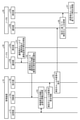
次に、図8を参照して、本実施形態に係る管理装置10による管理処理について説明する。図8は、管理処理手順を示すシーケンス図である。図8には、ノードAの測定情報に基づいて、ノードBの測定のルールが変更される場合が例示されている。図8のシーケンスは、例えば、ユーザが開始を指示する操作入力を行ったタイミングで開始される。
次に、図8を参照して、本実施形態に係る管理装置10による管理処理について説明する。図8は、管理処理手順を示すシーケンス図である。図8には、ノードAの測定情報に基づいて、ノードBの測定のルールが変更される場合が例示されている。図8のシーケンスは、例えば、ユーザが開始を指示する操作入力を行ったタイミングで開始される。
まず、ノード20(図8に示すノードA)において、測定部23aが、測定の項目や頻度が規定された通常のルール22aに従って、運用状態や通信品質の測定を実施して、測定情報を出力する(ステップS1)。また、通知部23bが、例えば、通知の頻度が規定されたルール22aに従って、通知の要否を判断して、最新の測定情報を管理装置10に通知する(ステップS2)。
管理装置10では、判断部13aが、ノード20から通知された測定情報と、記憶部12の運用情報12aとを用いて、ノードの測定のルール22aを変更する必要があるか否かを判断する(ステップS3~S4)。
そして、判断部13aがルールの変更が必要と判断した場合には、指示部13bが、関連するノード20(図8に示す例ではノードB)に、測定のルール22aの変更を指示する(ステップS5)。
測定のルール22aの変更を指示されたノード20(ノードB)では、通知部23bが、指示に基づいて測定のルールを変更し、記憶部22のルール22aを変更後のルールに更新する(ステップS6)。
その後、測定部23aは、変更後のルール22aに従って、測定を実施して測定情報を出力する(ステップS7)。また、通知部23bが、変更後のルール22aに従って、管理装置10に測定情報を通知する。以上の処理を繰り返すことにより、一連の管理処理が終了する。
以上、説明したように、本実施形態の管理装置10において、記憶部12が、運用情報を記憶する。また、判断部13aが、運用情報と、ノード20から通知された測定情報とを用いて、測定情報の測定のルール22aを変更する必要があるか否かを判断する。また、指示部13bが、ルールの変更が必要と判断された場合に、関連するノード20にルール22aの変更を指示する。
これにより、管理装置10は、テレメトリ情報の測定精度を維持しながら、テレメトリ情報の測定や通知の回数を低減することが可能となる。したがって、測定元や通知先のノード20の処理負荷が低減し、記憶容量の圧迫を抑止することが可能となる。
[他の実施形態]
上記実施形態の管理装置10は、通信システム1のノード20とは異なるハードウェアに実装されているが、これに限定されない。図9は、他の実施形態の管理装置を説明するための図である。例えば、図9(a)に示すように、管理装置10が管理機能部として、ノード20のいずれかに実装されてもよい。
上記実施形態の管理装置10は、通信システム1のノード20とは異なるハードウェアに実装されているが、これに限定されない。図9は、他の実施形態の管理装置を説明するための図である。例えば、図9(a)に示すように、管理装置10が管理機能部として、ノード20のいずれかに実装されてもよい。
あるいは、図9(b)に示すように、複数の管理装置10(管理機能部)が複数のノード20に実装されてもよい。この場合には、各管理機能部は、自ノード20と他の管理機能部とから測定情報を収集し、運用状態や通信品質の状況を監視する。そして、障害の発生や帯域制限等の状況の変化を検知した場合に、関連するノード20の管理機能部に、測定情報の測定項目や測定頻度等のルールの変更を指示する。
[プログラム]
上記実施形態に係る管理装置10およびノード20が実行する処理をコンピュータが実行可能な言語で記述したプログラムを作成することもできる。一実施形態として、管理装置10およびノード20は、パッケージソフトウェアやオンラインソフトウェアとして上記の管理処理を実行する管理プログラムを所望のコンピュータにインストールさせることによって実装できる。例えば、上記の管理プログラムを情報処理装置に実行させることにより、情報処理装置を管理装置10またはノード20として機能させることができる。ここで言う情報処理装置には、デスクトップ型またはノート型のパーソナルコンピュータが含まれる。また、その他にも、情報処理装置にはスマートフォン、携帯電話機やPHS(Personal Handyphone System)などの移動体通信端末、さらには、PDA(Personal Digital Assistant)などのスレート端末などがその範疇に含まれる。また、管理装置10の機能を、クラウドサーバに実装してもよい。
上記実施形態に係る管理装置10およびノード20が実行する処理をコンピュータが実行可能な言語で記述したプログラムを作成することもできる。一実施形態として、管理装置10およびノード20は、パッケージソフトウェアやオンラインソフトウェアとして上記の管理処理を実行する管理プログラムを所望のコンピュータにインストールさせることによって実装できる。例えば、上記の管理プログラムを情報処理装置に実行させることにより、情報処理装置を管理装置10またはノード20として機能させることができる。ここで言う情報処理装置には、デスクトップ型またはノート型のパーソナルコンピュータが含まれる。また、その他にも、情報処理装置にはスマートフォン、携帯電話機やPHS(Personal Handyphone System)などの移動体通信端末、さらには、PDA(Personal Digital Assistant)などのスレート端末などがその範疇に含まれる。また、管理装置10の機能を、クラウドサーバに実装してもよい。
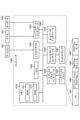
図10は、管理プログラムを実行するコンピュータの一例を示す図である。コンピュータ1000は、例えば、メモリ1010と、CPU1020と、ハードディスクドライブインタフェース1030と、ディスクドライブインタフェース1040と、シリアルポートインタフェース1050と、ビデオアダプタ1060と、ネットワークインタフェース1070とを有する。これらの各部は、バス1080によって接続される。
メモリ1010は、ROM(Read Only Memory)1011およびRAM1012を含む。ROM1011は、例えば、BIOS(Basic Input Output System)等のブートプログラムを記憶する。ハードディスクドライブインタフェース1030は、ハードディスクドライブ1031に接続される。ディスクドライブインタフェース1040は、ディスクドライブ1041に接続される。ディスクドライブ1041には、例えば、磁気ディスクや光ディスク等の着脱可能な記憶媒体が挿入される。シリアルポートインタフェース1050には、例えば、マウス1051およびキーボード1052が接続される。ビデオアダプタ1060には、例えば、ディスプレイ1061が接続される。
ここで、ハードディスクドライブ1031は、例えば、OS1091、アプリケーションプログラム1092、プログラムモジュール1093およびプログラムデータ1094を記憶する。上記実施形態で説明した各情報は、例えばハードディスクドライブ1031やメモリ1010に記憶される。
また、管理プログラムは、例えば、コンピュータ1000によって実行される指令が記述されたプログラムモジュール1093として、ハードディスクドライブ1031に記憶される。具体的には、上記実施形態で説明した管理装置10が実行する各処理が記述されたプログラムモジュール1093が、ハードディスクドライブ1031に記憶される。
また、管理プログラムによる情報処理に用いられるデータは、プログラムデータ1094として、例えば、ハードディスクドライブ1031に記憶される。そして、CPU1020が、ハードディスクドライブ1031に記憶されたプログラムモジュール1093やプログラムデータ1094を必要に応じてRAM1012に読み出して、上述した各手順を実行する。
なお、管理プログラムに係るプログラムモジュール1093やプログラムデータ1094は、ハードディスクドライブ1031に記憶される場合に限られず、例えば、着脱可能な記憶媒体に記憶されて、ディスクドライブ1041等を介してCPU1020によって読み出されてもよい。あるいは、管理プログラムに係るプログラムモジュール1093やプログラムデータ1094は、LANやWAN(Wide Area Network)等のネットワークを介して接続された他のコンピュータに記憶され、ネットワークインタフェース1070を介してCPU1020によって読み出されてもよい。
以上、本発明者によってなされた発明を適用した実施形態について説明したが、本実施形態による本発明の開示の一部をなす記述および図面により本発明は限定されることはない。すなわち、本実施形態に基づいて当業者等によりなされる他の実施形態、実施例および運用技術等は全て本発明の範疇に含まれる。
1 通信システム
10 管理装置
11 通信制御部
12 記憶部
12a 運用情報
13 制御部
13a 判断部
13b 指示部
20 ノード(ノード1~5、ノードA、B)
21 通信制御部
22 記憶部
22a ルール
23 制御部
23a 測定部
23b 通知部
10 管理装置
11 通信制御部
12 記憶部
12a 運用情報
13 制御部
13a 判断部
13b 指示部
20 ノード(ノード1~5、ノードA、B)
21 通信制御部
22 記憶部
22a ルール
23 制御部
23a 測定部
23b 通知部
Claims (6)
- 運用情報を記憶する記憶部と、
前記運用情報と、ノードから通知された測定情報とを用いて、測定情報の測定のルールを変更する必要があるか否かを判断する判断部と、
前記ルールの変更が必要と判断された場合に、関連するノードに前記ルールの変更を指示する指示部と、
を有することを特徴とする管理装置。 - 前記運用情報は、各ユーザの利用サービスに関する情報、前記ノードで構成されるネットワークの情報、および過去の測定情報を含むことを特徴とする請求項1に記載の管理装置。
- 前記測定情報は、運用状態および通信品質を示す情報を含むことを特徴とする請求項1に記載の管理装置。
- 前記ルールは、前記測定情報の項目および測定の頻度を含むことを特徴とする請求項1に記載の管理装置。
- 管理装置で実行される管理方法であって、
運用情報を記憶する記憶部を参照し、前記運用情報と、ノードから通知された測定情報とを用いて、測定情報の測定のルールを変更する必要があるか否かを判断する判断工程と、
前記ルールの変更が必要と判断された場合に、関連するノードに前記ルールの変更を指示する指示工程と、
を含んだことを特徴とする管理方法。 - 運用情報を記憶する記憶部を参照し、前記運用情報と、ノードから通知された測定情報とを用いて、測定情報の測定のルールを変更する必要があるか否かを判断する判断ステップと、
前記ルールの変更が必要と判断された場合に、関連するノードに前記ルールの変更を指示する指示ステップと、
をコンピュータに実行させるための管理プログラム。
Priority Applications (2)
| Application Number | Priority Date | Filing Date | Title |
|---|---|---|---|
| JP2022545163A JP7472990B2 (ja) | 2020-08-27 | 2020-08-27 | 管理装置、管理方法および管理プログラム |
| PCT/JP2020/032398 WO2022044211A1 (ja) | 2020-08-27 | 2020-08-27 | 管理装置、管理方法および管理プログラム |
Applications Claiming Priority (1)
| Application Number | Priority Date | Filing Date | Title |
|---|---|---|---|
| PCT/JP2020/032398 WO2022044211A1 (ja) | 2020-08-27 | 2020-08-27 | 管理装置、管理方法および管理プログラム |
Publications (1)
| Publication Number | Publication Date |
|---|---|
| WO2022044211A1 true WO2022044211A1 (ja) | 2022-03-03 |
Family
ID=80354890
Family Applications (1)
| Application Number | Title | Priority Date | Filing Date |
|---|---|---|---|
| PCT/JP2020/032398 Ceased WO2022044211A1 (ja) | 2020-08-27 | 2020-08-27 | 管理装置、管理方法および管理プログラム |
Country Status (2)
| Country | Link |
|---|---|
| JP (1) | JP7472990B2 (ja) |
| WO (1) | WO2022044211A1 (ja) |
Cited By (1)
| Publication number | Priority date | Publication date | Assignee | Title |
|---|---|---|---|---|
| JP7781359B1 (ja) * | 2025-02-25 | 2025-12-05 | 三菱電機株式会社 | ネットワーク管理システム、統合管理装置、収集装置およびネットワーク管理方法 |
Citations (1)
| Publication number | Priority date | Publication date | Assignee | Title |
|---|---|---|---|---|
| JP2017220840A (ja) * | 2016-06-08 | 2017-12-14 | 日本電信電話株式会社 | ネットワーク監視・制御装置、ネットワーク監視・制御方法、及びネットワーク監視・制御プログラム |
Family Cites Families (1)
| Publication number | Priority date | Publication date | Assignee | Title |
|---|---|---|---|---|
| US9668165B2 (en) | 2014-04-02 | 2017-05-30 | Softbank Corp. | Measuring communication quality via a mobile communication network |
-
2020
- 2020-08-27 JP JP2022545163A patent/JP7472990B2/ja active Active
- 2020-08-27 WO PCT/JP2020/032398 patent/WO2022044211A1/ja not_active Ceased
Patent Citations (1)
| Publication number | Priority date | Publication date | Assignee | Title |
|---|---|---|---|---|
| JP2017220840A (ja) * | 2016-06-08 | 2017-12-14 | 日本電信電話株式会社 | ネットワーク監視・制御装置、ネットワーク監視・制御方法、及びネットワーク監視・制御プログラム |
Cited By (1)
| Publication number | Priority date | Publication date | Assignee | Title |
|---|---|---|---|---|
| JP7781359B1 (ja) * | 2025-02-25 | 2025-12-05 | 三菱電機株式会社 | ネットワーク管理システム、統合管理装置、収集装置およびネットワーク管理方法 |
Also Published As
| Publication number | Publication date |
|---|---|
| JP7472990B2 (ja) | 2024-04-23 |
| JPWO2022044211A1 (ja) | 2022-03-03 |
Similar Documents
| Publication | Publication Date | Title |
|---|---|---|
| Das et al. | Adaptive stream processing using dynamic batch sizing | |
| CN108475207B (zh) | 云应用的联合自动缩放 | |
| KR20100109368A (ko) | 서버 로드 용량 결정 시스템 | |
| US20160117180A1 (en) | Auto-scaling thresholds in elastic computing environments | |
| US20140289719A1 (en) | Automatic version management | |
| CN111625592B (zh) | 分布式数据库的负载均衡方法和装置 | |
| CN112527544B (zh) | 一种服务器、触发熔断的方法及装置 | |
| US10171572B2 (en) | Server pool management | |
| WO2022059208A1 (ja) | 学習装置、学習方法及び学習プログラム | |
| JP7472990B2 (ja) | 管理装置、管理方法および管理プログラム | |
| US10616064B2 (en) | Soft reservation techniques and systems for virtualized environments | |
| CN114222001B (zh) | 边缘设备及方法、系统、电子设备及存储介质 | |
| CN116204310A (zh) | 一种资源调度方法、装置、设备及存储介质 | |
| US20180095440A1 (en) | Non-transitory computer-readable storage medium, activation control method, and activation control device | |
| CN110380982A (zh) | 一种流量控制方法及相关装置 | |
| US11632319B2 (en) | Processing device and moving method | |
| US10193823B2 (en) | Rich resource management incorporating usage statistics for fairness | |
| US20250330393A1 (en) | Application-specific sla thresholds for sd-wan application aware routing | |
| CN118138632A (zh) | 一种微服务架构的扩展处理方法和系统 | |
| CN119127232A (zh) | 一种微服务模块构建方法、装置、电子设备和存储介质 | |
| CN113254209A (zh) | 一种容量管理方法、装置、电子设备及可读存储介质 | |
| Lemoine | Kubernetes horizontal pod autoscaler enhanced design for protected workloads | |
| JP6554062B2 (ja) | 流量制御方法および流量制御装置 | |
| CN114205414A (zh) | 基于服务网格的数据处理方法、装置、电子设备和介质 | |
| JP6749871B2 (ja) | 情報処理システム及びデータ同期方法 |
Legal Events
| Date | Code | Title | Description |
|---|---|---|---|
| ENP | Entry into the national phase |
Ref document number: 2022545163 Country of ref document: JP Kind code of ref document: A |
|
| NENP | Non-entry into the national phase |
Ref country code: DE |
|
| 122 | Ep: pct application non-entry in european phase |
Ref document number: 20951464 Country of ref document: EP Kind code of ref document: A1 |