WO2022044151A1 - マーカ描画装置、システム及び方法 - Google Patents
マーカ描画装置、システム及び方法 Download PDFInfo
- Publication number
- WO2022044151A1 WO2022044151A1 PCT/JP2020/032147 JP2020032147W WO2022044151A1 WO 2022044151 A1 WO2022044151 A1 WO 2022044151A1 JP 2020032147 W JP2020032147 W JP 2020032147W WO 2022044151 A1 WO2022044151 A1 WO 2022044151A1
- Authority
- WO
- WIPO (PCT)
- Prior art keywords
- marker
- time
- spatial position
- tracking point
- drawing device
- Prior art date
- Legal status (The legal status is an assumption and is not a legal conclusion. Google has not performed a legal analysis and makes no representation as to the accuracy of the status listed.)
- Ceased
Links
Images









Classifications
-
- G—PHYSICS
- G06—COMPUTING OR CALCULATING; COUNTING
- G06F—ELECTRIC DIGITAL DATA PROCESSING
- G06F3/00—Input arrangements for transferring data to be processed into a form capable of being handled by the computer; Output arrangements for transferring data from processing unit to output unit, e.g. interface arrangements
- G06F3/01—Input arrangements or combined input and output arrangements for interaction between user and computer
- G06F3/03—Arrangements for converting the position or the displacement of a member into a coded form
- G06F3/033—Pointing devices displaced or positioned by the user, e.g. mice, trackballs, pens or joysticks; Accessories therefor
- G06F3/0346—Pointing devices displaced or positioned by the user, e.g. mice, trackballs, pens or joysticks; Accessories therefor with detection of the device orientation or free movement in a three-dimensional [3D] space, e.g. 3D mice, 6-DOF [six degrees of freedom] pointers using gyroscopes, accelerometers or tilt-sensors
-
- G—PHYSICS
- G06—COMPUTING OR CALCULATING; COUNTING
- G06F—ELECTRIC DIGITAL DATA PROCESSING
- G06F3/00—Input arrangements for transferring data to be processed into a form capable of being handled by the computer; Output arrangements for transferring data from processing unit to output unit, e.g. interface arrangements
- G06F3/01—Input arrangements or combined input and output arrangements for interaction between user and computer
- G06F3/048—Interaction techniques based on graphical user interfaces [GUI]
- G06F3/0481—Interaction techniques based on graphical user interfaces [GUI] based on specific properties of the displayed interaction object or a metaphor-based environment, e.g. interaction with desktop elements like windows or icons, or assisted by a cursor's changing behaviour or appearance
Definitions
- the present invention relates to a marker drawing device, a system and a method, and particularly relates to drawing a marker composed of an augmented reality (AR) object.
- AR augmented reality
- Patent Document 1 describes "instruction points” regarding "a display processing device, a display processing method, and a program that can provide a better user experience when performing virtual display in a real space”.
- the recognition processing unit performs recognition processing for recognizing an instruction point that indicates a point in real space for creating a virtual space image (virtual space image).
- the operation information acquisition unit changes during creation of a virtual rendering image.
- the virtual drawing data processing unit incorporates modifications based on the operation information and acquires virtual drawing data for drawing the virtual drawing image being created according to the instruction point.
- the virtual rendered image display processing unit performs display processing for displaying the virtual rendered image being created on the display screen in real time based on the virtual rendered data (summary excerpt).
- Patent Document 1 When drawing an AR object in Patent Document 1, "a user performs a touch operation of touching a line drawing operation button with the finger of the left hand after moving the fingertip of the right hand to a position where the virtual drawing image starts to be drawn". (Refer to paragraph 0030 of the patent document), "The user performs a touch operation by touching the line drawing operation button with the finger of the left hand after moving the fingertip of the right hand to the position where the virtual drawing image is finished" (Patent Document). As described in paragraph 0030), it was necessary to draw the AR object and to draw and end it separately.
- Patent Document 1 states that the drawing of the marker starts and ends. It is necessary to perform the operation for. This is a fact that the demonstrator who wants to talk about important things is made aware of the operation for drawing the marker, and as a result, the demonstrator's thinking and utterance are interrupted.
- the present invention has been made in view of the above circumstances, and draws a marker by an AR object without performing a marker drawing start operation and a drawing end operation separately from the marker drawing operation including the gesture drawing operation.
- the purpose is to perform a marker drawing start operation and a drawing end operation separately from the marker drawing operation including the gesture drawing operation.
- the present invention has the configuration described in the claims.
- the present invention has a camera that captures a subject, a ranging sensor that detects the spatial position of the subject, a display, a memory, the camera, the ranging sensor, the display, and the above.
- a marker drawing device including a processor connected to each of the memories, wherein the processor analyzes an image of the subject captured by the camera, and based on the output of the ranging sensor, the space of the subject. The position is recorded in the memory in chronological order, and the spatial position of the tracking point on the subject at the second time is within the drawing determination time based on the first time before the second time.
- a virtual real object consisting of a marker drawn at a spatial position where at least one of the spatial positions of the tracking point until the time when the drawing stop condition is satisfied is displayed on the display.
- the schematic diagram of the marker drawing system which concerns on this embodiment The figure which shows the field of view of the MR experience person. External view of HMD. HMD block diagram. Program block diagram expanded in RAM. Block diagram of VR service server. Block diagram of MR support server.
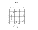
- the figure which shows the example of the locus data stored in RAM (the example where the start point and the end point match).
- the figure which shows the example of the locus data stored in RAM (the example which provides the margin).
- the figure which shows the example which the forward marker can draw.
- the figure which shows the drawing example of the forward direction marker The figure which shows the drawing example of the forward direction marker.
- AR objects virtual reality objects
- AR objects virtual reality objects
- an AR marker is drawn on the portion to be focused on, so that the portion to be focused on can be shared and visually recognized by a plurality of people, and the portion to be focused on can be visually recognized even after the finger is released.
- the present invention relates to a marker drawing device and a method capable of confirming that it is an AR display.
- a marker is drawn without using a controller. This eliminates the need to switch the controller, and since it is not necessary to switch to the drawing mode in the middle of the explanation, it is characterized in that it is a marker drawing device and method that can perform AR drawing by a natural operation.
- FIG. 1 is a schematic diagram of a marker drawing system 10 according to this embodiment.
- the MR experience person 2 wears the HMD2a on the head and visually recognizes the MR space 1.
- the MR experiencers 3 and 4 wear the HMDs 3a and 4a on their heads and visually recognize the MR space 1.
- Each of the HMDs 2a, 3a, and 4a is connected to the access point 1a by wireless communication by transmitting and receiving the wireless LAN signal 1b.
- the wireless LAN signal 1b is merely an example of a wireless communication signal, and is not limited to the LAN signal, and may be a wireless communication signal used in telephone network communication such as LTE, 4G, and 5G.
- the access point 1a is arranged in the MR space 1.
- the access point 1a is connected to the network 7 outside the MR space 1 and is connected to the VR service server 8 and the mixed reality support server (hereinafter referred to as “MR support server”) 9 placed on the HMD2a and 3a and the network 7. Have them communicate with each other.
- MR support server mixed reality support server
- the drawing target of the marker 6 is not limited to a real object, but may be an AR object of an automobile.
- MR space 1 is a space that assumes sales promotion of a car, and is not a space limited to one specific MR experience person 2, but multiple people like MR experience person 3 and 4 can experience MR at the same time. You may go.
- the MR experience person 2 is a product explainer and observes the same automobile 5 and marker 6 as the MR experience person 3 and 4 from different directions.
- MR experiencers 2, 3 and 4 wearing transparent (semi-transparent) or video see-through type HMD2a, 3a and 4a simultaneously visually recognize an actual automobile 5 and draw a marker 6 on it.
- the present embodiment can also be applied to an immersive HMD2a, 3a, 4a in which an automobile is displayed as an AR object and a marker 6 is superimposed on the vehicle and drawn.
- FIG. 2 is a diagram showing the field of view of the MR experience person 2 in FIG.
- the arm 2ar and the fingertip 2f of the MR experience person 2 and the marker 6 drawn from the fingertip are superimposed and displayed on the right front part of the automobile 5.
- the marker 6 can be seen superimposed on the automobile 5 from the MR experienced person 3 and the MR experienced person 4.
- FIG. 3 is an external view of HMD2a, 3a, and 4a as an example of a marker drawing device.
- the HMD2a is a video see-through type HMD. Since HMD3a and 4a have the same configuration as HMD2a, the description thereof will be omitted.
- the HMD2a includes a range-finding camera 112 having parallax and a display 102.
- the HMD2a captures the foreground with the ranging camera 112, and displays the marker 6 drawn by CG or the like on the display 102 arranged in front of the MR experience person 2 by synthesizing the image captured by the ranging camera 112.
- the range-finding camera 112 includes the left camera 112a and the right camera 112b, and is a range-finding camera for measuring the distance to the object being photographed.
- the display 102 is a flat display and includes a left-eye display 102a and a right-eye display 102b.
- the image for the left eye is displayed on the display 102a for the left eye
- the image for the right eye is displayed on the display 102b for the right eye.
- the HMD2a corresponds to the three-dimensional display.
- the method for realizing the three-dimensional display does not matter.
- the HMD2a includes a controller 100 and a mounting housing 190.
- the HMD2a is mounted on the head of the mounting housing 190.
- the display 102 superimposes the marker 6 on the real space image and projects it.
- the image of the AR object for the left eye is superimposed on the image captured by the left camera 112a
- the image of the AR object for the right eye is superimposed on the image captured by the right camera 112b and displayed on the display 102, so that the marker 6 looks as if it were a real space. It is displayed three-dimensionally (three-dimensionally) so that it is at a predetermined distance.
- FIG. 4 is a block diagram of HMD2a.
- the same ones as those in FIG. 5 are assigned the same numbers.
- the HMD2a is a distance measuring camera including a processor 101 including a CPU and an MPU, a display 102 (including a left-eye display 102a and a right-eye display 102b), a ROM 103, a RAM 104, a storage 105, an in-camera 111, a left camera 112a, and a right camera 112b.
- a processor 101 including a CPU and an MPU
- a display 102 including a left-eye display 102a and a right-eye display 102b
- a ROM 103 including a left-eye display 102a and a right-eye display 102b
- RAM 104 includes a storage 105, an in-camera 111, a left camera 112a, and a right camera 112b.
- microphone 121, speaker 122, operation interface (I / F) 130 (corresponding to an operation member), wireless LAN communication device 141 (for example, a device using Wifi (registered trademark)), proximity
- the sensor group 160 includes a GPS 161, a gyro sensor 162, a geomagnetic sensor 163, an acceleration sensor 164, an illuminance sensor 165, a proximity sensor 166, a depth sensor (ToF sensor) 167, and a line-of-sight detection sensor 168.
- the distance measuring camera 112 is used as the distance measuring sensor, and the distance measuring image (sensor) captured by the distance measuring camera 112 in the vertical and horizontal directions and the depth direction of the tracking point to be tracked for drawing the marker 6. It corresponds to the output.) Is analyzed and detected.
- the subject may be photographed by a single-view camera (so-called out-camera) that captures the outside world, and at the same time, the depth sensor 167 may measure the distance in the depth direction of the subject, and the gyro sensor 162 may measure the change in the position in the vertical and horizontal directions. ..
- the out-camera, the depth sensor 167, and the gyro sensor 162 are combined to form a distance measuring camera.
- the operation I / F 130 is, for example, a button provided on the side surface of the mounting housing 190.
- FIG. 5 shows a program block diagram expanded in the RAM 104.
- the program 200 and the data 210 necessary for executing the program 200 are expanded in the RAM 104.
- the program 200 includes an operating system 201 necessary for executing the basic operation of the HMD2a and a marker drawing application 202. Further, as another application example different from the marker drawing application 202, there may be application A203 and application B204.
- the locus data 211 of the fingertip of the MR experience person 2 is stored and expanded as the data necessary for drawing the marker 6.
- the locus data 211 is data in which the spatial coordinates of the fingertips are recorded along the time series, and includes the spatial coordinates and the time data.
- the HMD2a may include a part or all of the processes executed by the VR service server 8 and the MR support server 9 described below.
- FIG. 6 is a block diagram of the VR service server 8.
- the VR service server 8 includes a network interface (network I / F) 81 such as a wired LAN, a CPU 82, a RAM 83, and a storage 84, which are connected to each other via an internal bus 85.
- network I / F network interface
- the storage 84 may be combined with a flash ROM, a hard disk drive, or the like.
- the storage 84 stores the VR service program 86.
- the CPU 82 expands and executes the VR service program 86 in the RAM 83.
- the storage 84 stores the VR data 87 necessary for executing the VR service program 86.
- the VR data 87 for example, the three-dimensional VR object data of the automobile is stored, and the HMDs 2a, 3a, and 4a worn by the MR experiencers 2, 3, and 4 are configured as an immersive HMD. Then, MR experiencers 2, 3 and 4 may share a VR space, display a car made of a VR object in the VR space, and further draw a marker 6 to have a dialogue.
- FIG. 7 is a block diagram of the MR support server 9.
- the MR support server 9 includes a network I / F 91 such as a wired LAN, a CPU 92, a RAM 93, and a storage 94, which are connected to each other via an internal bus 95.
- the storage 94 may be combined with a flash ROM, a hard disk drive, or the like.
- the storage 94 includes a marker drawing program 96.
- the CPU 92 expands and executes the marker drawing program 96 in the RAM 93.
- the MR data 97 is the marker data required to execute the marker drawing program 96.
- the first embodiment is an embodiment in which a marker is drawn when the coordinates of a point to be tracked for drawing the marker (hereinafter referred to as “tracking point”) overlap with coordinates that are the same as or close to the past.
- FIG. 8 is a flowchart showing the flow of the marker drawing process according to the first embodiment.
- the processing example shown in FIG. 8 is an example of drawing a marker when the coordinates of the tracking point overlap with the coordinates within a certain time in the past.
- the HMDs 2a, 3a, and 4a log in to the MR support server 9 and perform user registration in order to share the same MR space 1 (S01).
- S01 MR space 1
- the HMD2a functions as a first marker drawing device for drawing a marker
- the HMD3a and 4a functions as a second marker drawing device for displaying a marker drawn by another marker drawing device
- the HMDs 2a, 3a, and 4a may function as a first marker drawing device and a second marker drawing device, respectively.
- the processor 101 of the HMD2a acquires a distance measurement image (including a subject image and distance data) captured by the distance measurement camera 112 (S02).
- the processor 101 analyzes the image of the subject captured in the distance measurement image, and identifies and registers the tracking object, for example, the fingertip 2f of the subject or the tip of the rod-shaped member held by the subject as a tracking point (S03).
- the fingertip 2f is used as the tracking point.
- the processor 101 associates the coordinates of the recognized tracking point with the time when the tracking point is detected (may be the time when the distance measurement image is captured) and records it in the trajectory data 211 (see FIG. 9) (S04).
- the coordinates of the tracking point registered in this step may be relative coordinates with respect to HMD2a.
- absolute coordinates that can be shared by the HMD2a, 3a and 4a are required in the process described later.
- the "absolute coordinates" here may be a spatial coordinate system defined in MR space 1 in addition to GPS system coordinates. For example, a combination of the base point space coordinates that specify the position of the HMD2a in the MR space 1 and the relative coordinates of the tracking point with respect to the HMD2a may be used.
- FIG. 9 is an example of the locus data 211 stored in the RAM 104.
- the real space seen from the HMD2a is divided into a plurality of blocks in a mesh shape (see FIG. 9A), and the coordinates are defined by the numbers uniquely indicating each block. Then, the coordinates (block number) at which the tracking point is detected and the detection time are stored in association with each other.
- Each block has a depth along the depth direction when viewed from HMD2a. That is, although each block is drawn as a two-dimensional square in FIG. 9, it is actually a rectangular parallelepiped or cubic space having a depth in the direction perpendicular to the paper surface of FIG. Therefore, the three-dimensional coordinates in one block are regarded as the same coordinates and recorded in the locus data 211.
- the coordinates of the tracking point are actually limited to one point in the three-dimensional coordinate system, but the coordinates within the allowable range that can be regarded as the same coordinates in the vicinity can be treated as the same coordinates. Further, by giving the block a width in the depth direction, even if there is a positional deviation of the tracking point in the depth direction from the viewpoint of HMD2a, it can be treated as the same coordinates.
- the processor 101 determines whether the coordinates that are the same as or close to the newly recorded coordinates have been recorded in the locus data 211 in the past (S05).
- the processor 101 detects the same coordinate C6 in the past as the time (121) when the current coordinate (C6) was detected.
- the time difference ⁇ t from the time (101) is calculated, and it is determined whether the time difference ⁇ t is included in the drawing determination time (S06).
- the “drawing determination time” is a predetermined time for determining whether or not the movement of the tracking point is a movement for drawing a marker. For example, it may be 1 second.
- the processor 101 determines whether or not the time difference ⁇ t is included in the “drawing determination time” by the following equation (1) (S06).
- -U_lim Upper limit of drawing judgment time. A value to determine that the tracking point is needed to move from the start point to the end point of the marker in order to draw the marker.
- step S11 If the processor 101 determines that the same or adjacent coordinates have not been recorded in the past (S05: No), or the time difference ⁇ t is not within the drawing determination time (S06: No), the process proceeds to step S11.
- the processor 101 connects the coordinates (C6, B6, ... D6, C6) between the time (101) when the same coordinate C6 was detected in the past and the time (121) when the current coordinate C6 was detected.
- the marker 6 is drawn and displayed on the display 102 of the HMD2a (S07).
- the coordinates (C6) of the past (time 101) and the coordinates of the position (C6) of the current fingertip 2f are the same in the locus data 211, and the history time (time 101) is specified. If it is within the range (for example, the time is greater than 100 and less than 110), the marker 6 having C6 as the start point and the end point is drawn.
- the processor 101 transmits the drawn spatial position information of the marker 6 to the MR support server 9 (S08), and the MR support server 9 transmits the spatial position information of the marker 6 to each of the HMDs 3a and 4a (S09).
- the position of the HMD2a does not deviate significantly within the drawing determination time
- only one base point space coordinate in the absolute coordinate space of the HMD2a for defining the spatial position information may be used, and the drawing determination time may be one. If the length is defined so that the deviation of the absolute coordinates of can be observed, the absolute coordinates of HMD2a may be recorded in the coordinates of the locus data 211 instead of the block number.
- each block is the relative coordinates of the HMD2a, and converting this to the absolute coordinates requires the base point space coordinates that are the positions of the HMD2a.
- the base point space coordinates at each measurement time are required, but if the HMD2a does not move, a common base point space coordinate value can be used.
- Each of the HMDs 3a and 4a displays the marker 6 on the respective display 102 based on the received spatial position information of the marker 6 (S10). At that time, each of the HMDs 3a and 4a is displayed by performing occlusion processing between the subject of the distance measuring image captured by the distance measuring camera 112 of each HMD 3a and 4a and the marker 6.
- a user's finger or the tip of a pointer held by the user is registered as a tracking point without using a controller, the coordinates of the tracking point are compared with the past coordinates, and a marker can be drawn if they match. Therefore, the user can display the marker in AR by moving the finger along the shape of the marker to be drawn without inputting the instruction to draw the marker.
- the drawn marker can be shared and visually recognized by multiple people existing in the same MR space 1.
- the second embodiment is an embodiment in which it is detected that a tracking point (for example, a fingertip) finger draws the same locus in space a plurality of times within a specified time, and the second and subsequent finger loci are drawn by AR. ..
- a tracking point for example, a fingertip
- the "trajectory” here is used to mean a trace that the tracking point has passed once.
- the current (immediately before) locus is expressed as the current spatial position of the finger.
- FIG. 10 is a flowchart showing the flow of the marker drawing process according to the second embodiment.
- the MR support server 9 When each of HMD2a, 3a, and 4a logs in to the MR support server 9 and registers as a user (S01), the MR support server 9 turns off the forward flag, the reverse flag, and the drawing flag (S101).
- the MR support server 9 has one forward flag and one reverse flag as a whole, that is, even if there are a plurality of tracking points, only one. On the other hand, there is one drawing flag for each tracking point. Therefore, the number of drawing flags is set to the same as the number of tracking points. After that, the distance measurement image is acquired (S02), the tracking point is recognized (S03), and the tracking point is recorded in the trajectory data (S04).
- step S11 If the same or close coordinates are not recorded in the past for a certain period (S102: No), the drawing flags of all tracking points are turned off (S103). Then, the process proceeds to step S11.
- step S102 the tracking point that traces the past trajectory is targeted regardless of the forward direction or the reverse direction.
- step S104 it is determined whether the coordinate immediately before the tracking point is the same as or close to the coordinate one after the past coordinate (reverse direction) (S106). If affirmative, that is, if the user traces in the reverse direction (S106: Yes), the reverse direction flag is turned ON (S107), and the process proceeds to step S108.
- step S106 If step S106 is negative (S106: No), the forward flag is ON, and the reverse flag is also ON (S108: Yes), the forward flag and the reverse flag are turned OFF (S109), and the process proceeds to step S103. move on. In this case, it is considered that the tracing direction has changed in the middle, so the count in step S111 is reset.
- the forward flag is ON and the reverse flag is not ON, that is, if either the forward flag or the reverse flag is ON and the other is OFF, or both are OFF (S108: No), the tracking point Turn on the drawing flag (S110).
- the counting of the number of tracking points with the drawing flag ON is started, and if the numerical value is equal to or greater than the specified number (S111: Yes), the marker drawing / HMD (own device) device displays the tracking points with the drawing flag ON. (S112). As a result, a marker is drawn when the length (the number of tracking points) of the specified number or more is traced. After that, the spatial position information of the marker is transmitted to the MR support server 9 (S08).
- step S08 onward the processes described in steps S09 to S11 are executed.
- the position of each time is indicated by using a block indicating a part of the real space, and the determination of step S21 or S24 is performed by the difference between the blocks. You may. In this case, by including a plurality of coordinates in one block, it is possible to absorb the fluctuation of the position of the tracking point and determine the marker drawing.
- FIG. 11A shows an example in which the forward marker can be drawn
- FIG. 11B shows an example in which the forward marker cannot be drawn.
- step S21 since the affirmative judgment of step S21 continues for a certain period at consecutive times, the forward marker can be drawn.
- step S21 since the affirmative judgment of step S21 does not continue at consecutive times, the forward marker cannot be drawn.
- the locus history overlaps with the points P1 and Pn, they are not drawn for a certain period of time or because the times are not continuous.
- the following restrictions may be provided because drawing is not performed due to accidental overlapping of trajectories.
- the part (area or volume) where the loci overlap is less than a certain value, it is not drawn.
- the drawing is not performed. This may correspond to either a forward marker (a shape drawn with a single stroke such as a circle, a quadrangle, or a triangle) or a reverse marker.
- the second locus portion may be drawn when the second locus of the repetition is closed, that is, when it overlaps with the third locus.
- the second locus is drawn after overlapping with the third locus.
- the direction changes once on the trajectory, and when the direction changes again, it is drawn. Similar to the above, it may be configured so that it is not drawn unless it is completely traced twice.
- the current spatial position of the tracking point and the past spatial position are not drawn simply by overlapping. .. This makes it difficult for the marker to be drawn unintentionally.
- the present invention is not limited to the above-mentioned first embodiment and the second embodiment, and various changes within the range not deviating from the gist of the invention, for example, a mode that holds even if they are replaced in reverse order in the steps of the flowchart, and unnecessary components.
- the present invention includes an embodiment in which a component that does not have or has a similar effect is replaced. Further, in the above embodiment, for example, the following application examples can be considered, and an embodiment in which they are appropriately combined is also included in the present invention.
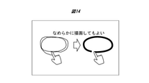
- a freehand line may be smoothed and converted into a smooth circle or straight line for drawing.
- [Application 3] You may draw the first locus so that only you can see it, and make it easier to trace the second one.
- the processor 101 constantly displays the locus history for a certain period of time, and draws by tracing the second locus before the first locus is hidden. At that time, the first locus is displayed only on the HMD2a. Or, if the first locus history and the second finger space position overlap, change the color of the locus history displayed only to you, for example, if it is a circle, you can draw a marker when you finish tracing to the second intersection. good. Furthermore, if you do not want to draw due to accidental overlap, you can stop by stopping the movement of your finger after the color changes and before reaching the intersection.
- the same effect can be obtained by drawing after changing the direction again.
- the marker is displayed on the HMD2a
- the position information and drawing information of the marker are also received by the HMD3a and 4a via the MR support server 9, and only the marker is shared with the HMD2a.
- a marker In a marker consisting of a closed region such as a circle, a marker may be attached to the entire inside of the closed region. For example, by making the area inside the outline of the marker a semi-transparent color, the part to be noticed can be emphasized more and the background part can be seen.
- the tracking point is the reflection point of the laser pointer and the locus of the laser pointer projected on the real object overlaps a plurality of times
- the locus may be drawn as a marker by AR.
- finger recognition with a camera or the like, it is possible to recognize the trajectory of what has moved in the foreground (against the original background).
- the pointer 11 whose tip point (spatial position) separated from the finger by a specified distance (corresponding to the pointer length) is linked to the movement of the finger with reference to the position of the finger is set by AR. It is displayed, and the tip point of the pointer 11 is set as the tracking point. Then, when the loci of the tips of the pointers 11 overlap each other a plurality of times, the marker 6 may be drawn by AR.
- the "designated direction" may be, for example, the axial direction of the finger, or may be the depth direction of the range-finding camera 112 or the depth sensor 167 provided in the HMD2a.
- MR space 1a Access point 1b: Wireless LAN signal 2, 3, 4: Experiencer 2a, 3a, 4a: HMD 2ar: Arm 2f: Fingertip 5: Automobile 6: Marker 7: Network 8: VR service server 9: MR support server 10: Marker drawing system 11: Pointer 81: Network I / F 82: CPU 83: RAM 84: Storage 85: Internal bus 86: VR service program 87: VR data 91: Network I / F 92: CPU 93: RAM 94: Storage 95: Internal bus 96: Marker drawing program 100: Controller 101: Processor 102: Display 102a: Left eye display 102b: Right eye display 103: ROM 104: RAM 105: Storage 106: Bus 111: In-camera 112: Distance measuring camera 112a: Left camera 112b: Right camera 121: Microphone 122: Speaker 130: Operation I / F 141: Wireless LAN communication device 142: Proximity wireless communication device 143: Telephone network communication device 150: Vibrat
Landscapes
- Engineering & Computer Science (AREA)
- General Engineering & Computer Science (AREA)
- Theoretical Computer Science (AREA)
- Human Computer Interaction (AREA)
- Physics & Mathematics (AREA)
- General Physics & Mathematics (AREA)
- User Interface Of Digital Computer (AREA)
Abstract
カメラが被写体を撮像した画像及び測距センサが検出した被写体の空間位置を示すセンサ出力を取得し、画像及び被写体の空間位置を時系列に沿って記録し、被写体上にある追跡点の第2時刻における空間位置が、第2時刻よりも前の第1時刻を基準とする描画判定時間内における追跡点の軌跡履歴を含む空間内に重なるかを判断し、肯定と判断すると、軌跡履歴、又は第2時刻から第2時刻よりも後に描画停止条件が成立する時刻までの追跡点の空間位置、の少なくとも一方が通過した空間位置に描画されたマーカからなる仮想現実物体をディスプレイに表示する。
Description
本発明は、マーカ描画装置、システム及び方法に係り、特に拡張現実(AR:Augmented Reality)オブジェクトからなるマーカの描画に関する。
ARオブジェクトを描画する技術として、特許文献1には、「実空間で仮想表示を行う場合により良好なユーザ体験を提供することができる表示処理装置及び表示処理方法、並びにプログラム」に関して、「指示点認識処理部は、仮想空間画像(仮想空間画像)を作成するための実空間上の点を指示する指示点を認識する認識処理を行う。操作情報取得部は、仮想レンダリング画像を作成中に変更するためのユーザ操作に応じた操作情報を取得する。仮想描画データ処理部は、操作情報に基づく修正を組み込んで、指示点に応じて作成中の仮想描画画像を描画するための仮想描画データを生成する。仮想レンダリング画像表示処理部は、仮想レンダリングデータに基づいて、作成中の仮想レンダリング画像をリアルタイムで表示画面に表示させる表示処理を行う(要約抜粋)」という記載がある。
特許文献1でARオブジェクトを描画する際には、「ユーザが、仮想描画画像を描き始める位置まで右手の指先を移動させた後、左手の指でライン描画操作ボタンをタッチするタッチ操作を行う」(特許文献の段落0030参照)、「ユーザが、仮想描画画像を描き終える位置まで右手の指先を移動させた後、左手の指でライン描画操作ボタンをタッチするタッチ操作を行う」(特許文献の段落0030参照)とあるように、ARオブジェクトの描画と、それを描画させる、及び終了させる操作が別途必要だった。
従って、例えばARオブジェクトを複数人で共有してデモンストレーションを行っている場合に、ARオブジェクトを用いて関心領域を描画するためのマーカを付けようとすると、特許文献1ではマーカの描画開始、終了のための操作を行う必要がある。これは、重要な話をしたいと考えるデモンストレーターにとって、マーカを描画するための操作を意識して行わせる結果、デモンストレーターの思考や発話の中断を招くという実情がある。
本発明は上記実情に鑑みてなされたものであり、マーカの描画開始操作や描画終了操作をゼスチャーによるものも含めてマーカの描画操作とは別途に行うことなくARオブジェクトによるマーカを描画することを目的とする。
上記課題を解決するために、本発明は、特許請求の範囲に記載の構成を備える。その一例をあげるならば、本発明は、被写体を撮像するカメラと、前記被写体の空間位置を検出する測距センサと、ディスプレイと、メモリと、前記カメラ、前記測距センサ、前記ディスプレイ、及び前記メモリのそれぞれに接続されたプロセッサと、を備えるマーカ描画装置であって、前記プロセッサは、前記カメラが前記被写体を撮像した画像を解析し、前記測距センサの出力に基づいて、前記被写体の空間位置を時系列に沿って前記メモリに記録し、前記被写体上にある追跡点の第2時刻における空間位置が、前記第2時刻よりも前の第1時刻を基準とする描画判定時間内における前記追跡点の軌跡履歴を含む空間内に重なるかを判断し、前記第2時刻における前記追跡点の空間位置が前記軌跡履歴に重なる場合は、前記軌跡履歴、又は前記第2時刻から当該第2時刻よりも後に描画停止条件が成立する時刻までの前記追跡点の空間位置、の少なくとも一方が通過した空間位置に描画されたマーカからなる仮想現実物体を前記ディスプレイに表示する。
本発明によれば、マーカの描画開始操作や描画終了操作をゼスチャーによるものも含めてマーカの描画操作とは別途に行うことなくARオブジェクトによるマーカを描画することができる。なお、上記した以外の課題、構成及び効果は、以下の実施形態の説明により明らかにされる。
以下、図面を用いて本発明の実施形態について説明する。全図を通じて同一の構成には同一の符号を付して重複説明を省略する。
<各実施形態に共通する説明>
初めに、本実施形態の概略について説明する。
初めに、本実施形態の概略について説明する。
ARを用いた会議、プレゼンテーション等では、立体として空間上に見えるARオブジェクト(仮想現実物体)や現実物体の注目させたい部分にARオブジェクトでマーカの描画が行えると便利である。また、通常の会議、プレゼンテーション等で説明を行う際でも、現実物体の注目させたい部分を指先、指示棒等で繰り返しなぞることは自然な動作である。
本実施形態は、上記の動作が行われた時に、その注目させたい部分にARのマーカを描くことで、注目させたい部分を複数人で共有して視認し、指が離れた後も注目部分であることをAR表示により確認できるマーカ描画装置及び方法に関する。
更に、従来技術でもコントローラのボタン操作や、ゼスチャーにより描画モードへ切り替える、等の動作により空間にAR描画することは可能であったが、本実施形態では、コントローラを使用することなくマーカを描画することにより、コントローラの持ち替えの手間が不要になり、説明途中での描画モードへの切り替えが不要なため自然な動作でAR描画が行えるマーカ描画装置及び方法である点に特徴がある。
(マーカ描画システムの構成)
図1は、本実施形態に係るマーカ描画システム10の概要図である。
図1は、本実施形態に係るマーカ描画システム10の概要図である。
図1にて、MR体験者2はHMD2aを頭部に装着し、MR空間1を視認する。同様にMR体験者3、4は、HMD3a、4aを頭部に装着し、MR空間1を視認する。
HMD2a、3a、4aのそれぞれは、アクセスポイント1aと、無線LAN信号1bを送受信して無線通信接続される。無線LAN信号1bは、無線通信信号の一例にすぎず、LAN信号に限定されることなく、LTE、4G、5Gといった電話網通信で用いられる無線通信信号でもよい。
アクセスポイント1aは、MR空間1に配置されている。そしてアクセスポイント1aは、MR空間1の外のネットワーク7に接続して、HMD2a、3aとネットワーク7上に置かれているVRサービスサーバ8及び複合現実支援サーバ(以下「MR支援サーバ」)9のそれぞれと通信を行わせる。VR(Virtual Reality)とは、仮想現実空間のことである。
現実空間には、現実物体からなる自動車5がある。この自動車5に隣接した空間がマーカ6の描画対象である。マーカ6の描画対象は現実物体に限らず、自動車のARオブジェクトであってもよい。
MR空間1は、車のセールスプロモーションを想定した空間であり、特定の一人のMR体験者2に限定された空間ではなく、MR体験者3、4のように、複数の人が同時にMR体験を行っていてもよい。MR体験者2は商品説明員であって、MR体験者3、4と同じ自動車5及びマーカ6を異なる方向から観測している。
図1では、透過型(半透過型)又はビデオシースルー型のHMD2a、3a、4aを装着したMR体験者2,3,4が、現実の自動車5を同時に視認し、それにマーカ6を重ねて描画したが、没入型のHMD2a、3a、4aにARオブジェクトで自動車を表示しそれにマーカ6を重ねて描画する態様でも、本実施形態は適用できる。
図2は、図1におけるMR体験者2の視界を示す図である。
図2に示すようにMR体験者2の視界では、自動車5の右前部にMR体験者2の腕2ar及び指先2fと、あたかも指先から描画されたマーカ6が重ねて表示される。MR体験者3、MR体験者4からもマーカ6が自動車5に重ねて表示されて見える。
但し、MR体験者2、3、4を基準として、マーカ6と自動車5とでオクルージョン処理を行って表示される。すなわち、HMD3a、4aでは、現実物体である自動車5とマーカ6の距離の前後関係が反映されて表示される。従って、MR体験者4は、マーカ6が自動車よりも前にあるので、マーカ6の一部分が自動車5で隠されて見えるように、マーカ6の描画データを加工するオクルージョン処理を行う。
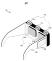
図3は、マーカ描画装置の一例としてのHMD2a、3a、4aの外観図である。HMD2aは、ビデオシースルー型のHMDである。HMD3a、4aは、HMD2aと同じ構成であるため説明を省略する。
HMD2aは、視差を有する測距カメラ112とディスプレイ102を備える。HMD2aは、測距カメラ112で前景を撮影し、MR体験者2の前面に配置するディスプレイ102に、測距カメラ112で撮影する画像にCG等で描画したマーカ6を合成して表示する。
測距カメラ112は、左カメラ112a及び右カメラ112bを含み、撮影している対象物との距離を測るための測距カメラである。ディスプレイ102は平面ディスプレイであり、左目用ディスプレイ102a及び右目用ディスプレイ102bを含む。左目用ディスプレイ102aには左目用の画像、右目用ディスプレイ102bには右目用画像を表示する。これにより、HMD2aは、3次元表示に対応している。なお、本願ではHMD2aは3次元表示ができればよいため、3次元表示の実現方法は問わない。
更にHMD2aは、コントローラ100、及び装着用筐体190を備える。装着用筐体190で、HMD2aを頭部に装着する。
ディスプレイ102は、マーカ6を、現実空間画像に重畳して映し出す。この時、左カメラ112aで撮影する画像に左目用ARオブジェクトの画像を、右カメラ112bで撮影する画像に右目用ARオブジェクトの画像を重畳してディスプレイ102に表示して、マーカ6があたかも現実空間の所定の距離にあるように立体的(3次元的に)に表示する。
図4は、HMD2aのブロック図である。図4にて、図5と同一のものには同一の番号を付している。
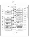
HMD2aは、CPUやMPUからなるプロセッサ101、ディスプレイ102(左目用ディスプレイ102a及び右目用ディスプレイ102bを含む)、ROM103、RAM104、ストレージ105、インカメラ111、左カメラ112a及び右カメラ112bを含む測距カメラ112、マイク121、スピーカ122、操作インタフェース(I/F)130(操作部材に相当する)、無線LAN通信器141(例えばWifi(登録商標)を使用した機器)、近接無線通信器142(例えばBluetooth(登録商標)を使用した機器)、LTE、4G、5Gに対応した電話網通信器143、バイブレータ150、センサ群160、及びRTC170を備え、これらがバス106を介して互いに接続されている。
センサ群160は、GPS161、ジャイロセンサ162、地磁気センサ163、加速度センサ164、照度センサ165、近接センサ166、深度センサ(ToFセンサ)167及び視線検出センサ168を含む。本実施形態では、測距センサとして測距カメラ112を用い、マーカ6を描画するために追跡する追跡点の上下左右方向及び奥行方向の空間位置を測距カメラ112が撮像した測距画像(センサ出力に相当する。)を解析して検出する。しかし、外界を撮像する単視点のカメラ(いわゆるアウトカメラ)で被写体を撮影し、同時に深度センサ167で被写体の奥行方向の距離、ジャイロセンサ162で上下左右方向の位置の変化を測定してもよい。この場合、アウトカメラと深度センサ167、ジャイロセンサ162とを組み合わせて測距カメラを構成する。
操作I/F130は、例えば装着用筐体190の側面に備えられたボタンである。
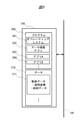
図5は、RAM104に展開されるプログラムブロック図を示す。
RAM104には、プログラム200とプログラム200を実行するために必要なデータ210とが展開される。
プログラム200は、HMD2aの基本動作の実行に必要なオペレーティングシステム201と、マーカ描画アプリ202がある。更にマーカ描画アプリ202とは異なる他のアプリ例として、アプリA203、アプリB204があってもよい。
データ210には、マーカ6の描画に必要なデータとして、MR体験者2の指先の軌跡データ211が記憶・展開される。軌跡データ211は、指先の空間座標が時系列に沿って記録されたデータであり、空間座標と時刻データとが含まれる。
なおHMD2aは、下記で説明するVRサービスサーバ8やMR支援サーバ9で実行する処理の一部もしくは全部を含んでもよい。
図6は、VRサービスサーバ8のブロック図である。VRサービスサーバ8は、有線LAN等のネットワークインターフェース(ネットワークI/F)81、CPU82、RAM83、ストレージ84を含み、これらが内部バス85を介して互いに接続される。
ストレージ84はFlash ROMのほか、ハードディスクドライブ等と組み合わせたものであってもよい。ストレージ84は、VRサービスプログラム86を格納する。CPU82は、VRサービスプログラム86をRAM83に展開して実行する。
更にストレージ84は、VRサービスプログラム86を実行するのに必要なVRデータ87を格納する。
VRデータ87として、例えば自動車の3次元VRオブジェクトデータを格納しておくと共に、MR体験者2、3、4が装着するHMD2a、3a、4aを没入型のHMDとして構成する。そして、MR体験者2、3、4がVR空間を共有し、そのVR空間にVRオブジェクトからなる自動車を表示し、更にマーカ6を描画して対話をしてもよい。
図7は、MR支援サーバ9のブロック図である。MR支援サーバ9は、有線LAN等のネットワークI/F91、CPU92、RAM93,ストレージ94を含み、これらが内部バス95を介して互いに接続される。
ストレージ94はFlash ROMのほか、ハードディスクドライブ等と組み合わせたものであってもよい。ストレージ94は、マーカ描画プログラム96を含む。CPU92は、マーカ描画プログラム96をRAM93に展開して実行する。
またMRデータ97は、マーカ描画プログラム96を実行するのに必要なマーカデータである。
<第1実施形態>
第1実施形態は、マーカを描画するために追跡する点(以下「追跡点」という)の座標が過去と同一又は近接する座標に重なるとマーカを描画する実施形態である。
第1実施形態は、マーカを描画するために追跡する点(以下「追跡点」という)の座標が過去と同一又は近接する座標に重なるとマーカを描画する実施形態である。
図8は、第1実施形態に係るマーカ描画処理の流れを示すフローチャートである。図8に示す処理例は、追跡点の座標が、過去の一定時間内の座標と重なったらマーカを描画する例である。
MR支援サーバ9のCPU92はマーカ描画プログラム96を実行し、マーカ描画システム10が起動しているものとする。HMD2a、3a、4aは、同一のMR空間1を共有するために、MR支援サーバ9にログインしてユーザ登録を行う(S01)。以下、説明の便宜のため、HMD2aがマーカを描画する第1マーカ描画装置として機能し、HMD3a、4aが他のマーカ描画装置が描画したマーカを表示する第2マーカ描画装置として機能する例について説明するが、HMD2a、3a、4aはそれぞれ第1マーカ描画装置、第2マーカ描画装置として機能してもよい。
HMD2aのプロセッサ101は、測距カメラ112で撮像した測距画像(被写体画像と距離データとを含む)を取得する(S02)。
プロセッサ101は、測距画像に撮像された被写体の画像解析を行い、追跡対象物、例えば被写体の指先2fや被写体が把持した棒状部材の先端を追跡点として識別し登録する(S03)。本例では指先2fを追跡点とする。
プロセッサ101は、認識した追跡点の座標と追跡点を検出した時刻(測距画像の撮像時刻でもよい)を関連付けて軌跡データ211(図9参照)に記録する(S04)。本ステップで登録する追跡点の座標は、HMD2aを基準とした相対座標でもよい。但し、他のHMD3a、4aでマーカ6を共有するためには後述する処理において、HMD2a、3a、4aで共有できる絶対座標が必要となる。ここでいう「絶対座標」とは、GPS系座標の他、MR空間1内で定義された空間座標系でもよい。例えばHMD2aのMR空間1内の位置を特定する基点空間座標と、HMD2aを基準とする追跡点の相対座標との組み合わせでもよい。
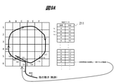
図9は、RAM104に記憶される軌跡データ211の例である。軌跡データ211では、HMD2aからみた現実空間をメッシュ状に複数のブロックに分割し(図9(a)参照)、各ブロックを固有に示す番号で座標を定義する。そして、追跡点が検出された座標(ブロック番号)と、検出時刻とを対応づけて格納する。
各ブロックは、HMD2aからみて奥行方向に沿った深さを有している。すなわち、各ブロックは、図9では2次元の正方形として描画されているが、実際には、図9の紙面垂直方向に深さを持った直方体状、又は立方体状の空間である。よって、一つのブロック内の3次元座標は、同一の座標とみなして軌跡データ211に記録する。
これにより、実際は追跡点の座標は3次元座標系での1点に限定されるが、近隣の同一の座標とみなせる許容範囲にある座標は、同一の座標として扱える。また、ブロックに奥行方向の幅を持たせることで、HMD2aからみて、追跡点の奥行方向の位置ズレがあっても同一の座標として扱える。
プロセッサ101は、新たに記録された座標と同じ又は近接する座標が軌跡データ211に過去記録されているかを判断する(S05)。
プロセッサ101は、今回の座標(C6)がすでに軌跡データ211に書き込まれていたら(S05:Yes)、今回の座標(C6)が検出された時刻(121)と過去に同一の座標C6が検出された時刻(101)との時間差Δtを演算し、時間差Δtか描画判定時間内に含まれるかを判断する(S06)。「描画判定時間」は、追跡点の動きがマーカを描画するための動きであるか否かを判定するために予め定義された時間である。例えば1秒でもよい。
プロセッサ101は、下式(1)により、時間差Δtが「描画判定時間」に含まれるか判断する(S06)。
L_lim<Δt<U_lim・・・(1)
ここで、
・L_lim:描画判定時間下限値。マーカを描画せず、単に追跡点が測距画像に撮像されているだけの状態かを判断するための値。
・U_lim:描画判定時間上限値。マーカを描画するために追跡点がマーカの始点から終点に移動するために必要と判断するための値。
L_lim<Δt<U_lim・・・(1)
ここで、
・L_lim:描画判定時間下限値。マーカを描画せず、単に追跡点が測距画像に撮像されているだけの状態かを判断するための値。
・U_lim:描画判定時間上限値。マーカを描画するために追跡点がマーカの始点から終点に移動するために必要と判断するための値。
プロセッサ101が、過去に同じ又は近接する座標が記録されていない(S05:No)、又は時間差Δtは描画判定時間内にないと判断すると(S06:No)、ステップS11へ進む。
プロセッサ101が、時間差Δtは描画判定時間に含まれると判断すると(S06:Yes)、マーカ描画処理を行う(S07)。
プロセッサ101は、過去に同一の座標C6が検出された時刻(101)から今回の座標C6が検出された時刻(121)までの間の座標(C6、B6、・・・D6、C6)をつなぐマーカ6を描画し、HMD2aのディスプレイ102に表示する(S07)。
本例では、図9Aに示すように、軌跡データ211において過去(時刻101)の座標(C6)と現在の指先2fの位置(C6)の座標が同じで、履歴の時刻(時刻101)が指定範囲内(例えば時刻が100より大きく110未満)ならば、C6を始点、終点とするマーカ6を描画する。
また、図9Bマージン領域を設定する場合は、過去(時刻101)の位置(C6)と現在の指先2fの位置の座標が近接(C5)していて、時間差Δtが描画判定時間内ならば、(C6)を始点、(C6又はC5)を終点とするマーカ6を描画する。
プロセッサ101は、描画したマーカ6の空間位置情報をMR支援サーバ9へ送信し(S08)、MR支援サーバ9は、HMD3a、4aのそれぞれにマーカ6の空間位置情報を送信する(S09)。描画判定時間内に、HMD2aの位置は大きくはずれないという前提であれば、空間位置情報を定義するためのHMD2aの絶対座標空間内における基点空間座標は一つだけでもよいし、描画判定時間がHMD2aの絶対座標のずれを観測できる程度の長さで定義されていれば、軌跡データ211の座標にブロック番号ではなくHMD2aの絶対座標を記録すればよい。即ち、各ブロックは、HMD2aの相対座標であり、これを絶対座標に変換するのは、HMD2aの位置である基点空間座標が必要である。言い方を変えると、本来、各測定時刻での基点空間座標が必要であるが、HMD2aが動かなければ、共通の基点空間座標の値を用いることができる。
HMD3a、4aのそれぞれは、受信したマーカ6の空間位置情報を基に、それぞれのディスプレイ102にマーカ6を表示する(S10)。その際、HMD3a、4aのそれぞれは、各HMD3a、4aの測距カメラ112で撮像した測距画像の被写体とマーカ6との間でオクルージョン処理をして表示する。
ログアウト処理がされなければ(S11:No)ステップS02へ戻る。ログアウトをすると(S11:Yes)と一連の処理を終了する。
本実施形態によれば、コントローラを用いることなく、ユーザの指やユーザが把持したポインタの先端を追跡点として登録し、その追跡点の座標を過去の座標と比べ、一致すればマーカを描ける。従って、ユーザはマーカを描く指示の入力操作をすることなく、描きたいマーカの形状に沿って指を動かせばマーカをARで表示させることができる。
更に描画したマーカを同一のMR空間1に存在する複数人で共有して視認することもできる。
<第2実施形態>
第2実施形態は、追跡点(例えば指先)指が空間上に同じ軌跡を指定時間内に複数回描いたことを検知して、2回目以降の指の軌跡をARで描画する実施形態である。プレゼンテーションで説明時に、ある注目点を強調する際には、指で円を複数回描く、指を強調したい部分の上で往復させる、等の動作をすることがあるため、その動作を認識して描画を行う。ここでいう「軌跡」とは、追跡点が1度通った跡という意味で使用している。本実施形態では、「過去の軌跡」と「現在の軌跡」と二つの軌跡がある。そこで、両者を区別するために、過去の軌跡を「軌跡履歴」と表現する。現在(直前)の軌跡は、現在の指の空間位置と表現する。
第2実施形態は、追跡点(例えば指先)指が空間上に同じ軌跡を指定時間内に複数回描いたことを検知して、2回目以降の指の軌跡をARで描画する実施形態である。プレゼンテーションで説明時に、ある注目点を強調する際には、指で円を複数回描く、指を強調したい部分の上で往復させる、等の動作をすることがあるため、その動作を認識して描画を行う。ここでいう「軌跡」とは、追跡点が1度通った跡という意味で使用している。本実施形態では、「過去の軌跡」と「現在の軌跡」と二つの軌跡がある。そこで、両者を区別するために、過去の軌跡を「軌跡履歴」と表現する。現在(直前)の軌跡は、現在の指の空間位置と表現する。
図10は、第2実施形態に係るマーカ描画処理の流れを示すフローチャートである。
HMD2a、3a、4aのそれぞれは、MR支援サーバ9にログインしてユーザ登録を行うと(S01)、MR支援サーバ9は、順方向フラグ、逆方向フラグ、描画フラグをOFFにする(S101)。MR支援サーバ9は、順方向フラグ及び逆方向フラグのそれぞれを全体に一つ、即ち複数の追跡点があっても、1つだけ有する。一方、描画フラグは、追跡点1つにつき1つ有する。従って、描画フラグは、追跡点の数と同数設けられる。その後、測距画像を取得し(S02)、追跡点を認識し(S03)、軌跡データに記録する(S04)。
一定期間の過去に、同じまたは近接する座標が記録されていなければ(S102:No)、全追跡点の描画フラグをOFFにする(S103)。その後ステップS11へ進む。
ステップS102では、順方向又は逆方向に関係なく、過去の軌跡をなぞった追跡点を対象にする。
一定期間の過去に、同じまたは近接する座標が記録されていれば(S102:Yes)、追跡点の一つ前の座標が過去の座標の一つ前の座標と同一又は近接している(順方向)かを判定する(S104)。肯定、即ちユーザが順方向になぞれば(S104:Yes)、順方向フラグをONにして(S105)、ステップS106へ進む。
ステップS104が否定であれば(S104:No)、追跡点の一つ前の座標が過去の座標の一つ後の座標と同一又は近接している(逆方向)かを判定する(S106)。肯定、即ちユーザが逆方向になぞれば(S106:Yes)、逆方向フラグをONにして(S107)、ステップS108へ進む。
ステップS106が否定(S106:No)であり、順方向フラグがON、かつ逆方向フラグもONであれば(S108:Yes)、順方向フラグ及び逆方向フラグをOFFにし(S109)、ステップS103へ進む。この場合は、途中でなぞる方向が変わったと考えられるので、ステップS111のカウントをリセットする。
順方向フラグがONかつ逆方向フラグもON、ではない、即ち、順方向フラグ又は逆方向フラグのどちらか一方がONで他方がOFF、又は両方OFFであれば(S108:No)、追跡点の描画フラグをONにする(S110)。
描画フラグがONの追跡点の数のカウントを開始し、その数値が指定の数以上であると(S111:Yes)、描画フラグONの追跡点にマーカ描画・HMD(自装置)装置で表示する(S112)。これにより、指定の数以上の長さ(追跡点の数)をなぞるとマーカが描画される。その後、マーカの空間位置情報をMR支援サーバ9に送信する(S08)。
ステップS08以降は、既述のステップS09~S11までの処理を実行する。
更に第1実施形態と同様、追跡点の位置を示すのに、現実空間の一部領域を示すブロックを用いて各時刻の位置を表し、ブロック間の異同により、ステップS21又はS24の判定を行ってもよい。この場合、1ブロックに複数の座標を含めることで、追跡点の位置の揺らぎを吸収してマーカ描画の判定を行うことができる。
図11Aは、順方向マーカが描画できる例を示し、図11Bは、順方向マーカが描画できない例を示す。
図11Aでは、連続した時刻でステップS21の肯定の判断が一定期間続くので順方向マーカが描画できている。
一方、図11Bでは、連続した時刻でステップS21の肯定の判断が続かないので、順方向マーカが描画できない。図11Bでは、点P1、Pnとで軌跡履歴は重なるが一定期間連続しないか、時刻が連続しないため描画しない。
上記第1実施形態、第2実施形態において、偶然軌跡が重なることで描画が行われないために、下記制限を設けてもよい。一例として、軌跡が重なる部分(面積又は体積)が一定値以下の場合は描画しない。例えば図11Bのように、軌跡が交差する場合などは描画しない。これは、順方向マーカ(円や四角形、三角形のように一筆書きでかける形状)や、逆方向マーカのどちらの対応でもよい。
また図12に示すように、順方向マーカを書く動作の場合、繰り返しの2回目の軌跡が閉じた時、すなわち、3回目の軌跡と重なった時に2回目の軌跡部分を描画してもよい。その際、図13に示すように、3回目の軌跡と重なってから2回目の軌跡を描画する。これにより、完全に2回なぞらないと描画されず、偶然軌跡が重なったことで、描画が行われることが防止できる。
また往復の直線の場合、軌跡上で方向が一度変わり、再度方向が変わったら描画する。上記と同様、完全に2回なぞらないと描画しないように構成してもよい。
本実施形態によれば、第1実施形態の効果に加えて、軌跡が重なってからマーカを描画することで、追跡点の現在の空間位置と過去の空間位置とが単に重なっただけでは描画されない。これにより、マーカが意図せずに描画されにくくなる。
<その他の実施形態>
本発明は上記第1実施形態、第2実施形態に限定されず、発明の趣旨を逸脱しない範囲での各種変更、例えばフローチャートのステップにおいて逆順に置き換えても成立する態様や、不要な構成要素を有していなかったり、同様の効果を奏する構成要素を置換したりする態様は、本発明に含まれる。また、上記実施形態には、例えば下記の応用例が考えられ、適宜組みあわせた態様も、本発明に含まれる。
本発明は上記第1実施形態、第2実施形態に限定されず、発明の趣旨を逸脱しない範囲での各種変更、例えばフローチャートのステップにおいて逆順に置き換えても成立する態様や、不要な構成要素を有していなかったり、同様の効果を奏する構成要素を置換したりする態様は、本発明に含まれる。また、上記実施形態には、例えば下記の応用例が考えられ、適宜組みあわせた態様も、本発明に含まれる。
[応用例1]
なぞる回数で線種を変える。2回で黒、3回で赤、など色を変える。太さ、点線、等形状を変える。
なぞる回数で線種を変える。2回で黒、3回で赤、など色を変える。太さ、点線、等形状を変える。
[応用2]
図14に示すように、フリーハンドの線に対してスムージング処理を施し、滑らかな円や直線に変換して描画してもよい。
図14に示すように、フリーハンドの線に対してスムージング処理を施し、滑らかな円や直線に変換して描画してもよい。
[応用3]
一回目の軌跡を自分だけに見えるように描画して、2回目をなぞりやすくしてもよい。プロセッサ101は、軌跡履歴を常時一定時間表示させ、1回目の軌跡が非表示になる前に2回目をなぞると描画する。その際、HMD2aにだけ1回目の軌跡を表示する。又は、1回目の軌跡履歴と2回目の指の空間位置が重なったら自分だけに表示している軌跡履歴の色を変え、例えば円ならば2回目の交点までなぞり終えたらマーカを描画してもよい。更に、偶然重なった等で描画したくない時は、色が変わってから交点に達する前に指の動きを止めれば中止できる。逆方向マーカ(往復の線)の場合は、再度方向転換したら描画する、等で同様の効果が得られる。HMD2aにマーカを表示すると、そのマーカの位置情報や描画情報は、MR支援サーバ9を介してHMD3a、4aにも受信され、マーカだけをHMD2aと共有する。
一回目の軌跡を自分だけに見えるように描画して、2回目をなぞりやすくしてもよい。プロセッサ101は、軌跡履歴を常時一定時間表示させ、1回目の軌跡が非表示になる前に2回目をなぞると描画する。その際、HMD2aにだけ1回目の軌跡を表示する。又は、1回目の軌跡履歴と2回目の指の空間位置が重なったら自分だけに表示している軌跡履歴の色を変え、例えば円ならば2回目の交点までなぞり終えたらマーカを描画してもよい。更に、偶然重なった等で描画したくない時は、色が変わってから交点に達する前に指の動きを止めれば中止できる。逆方向マーカ(往復の線)の場合は、再度方向転換したら描画する、等で同様の効果が得られる。HMD2aにマーカを表示すると、そのマーカの位置情報や描画情報は、MR支援サーバ9を介してHMD3a、4aにも受信され、マーカだけをHMD2aと共有する。
[応用4]
描画する人が複数いる場合には、描画する人ごとにマーカの色、線種を異ならせることで、誰が描画したマーカであるかの判別を容易にする。本例では、軌跡の検知を複数のHMDのうちの一つのHMDに搭載されたカメラで行う場合を説明する。HMD2a、3a、4aがMR支援サーバ9にログインすると、MR支援サーバ9がいずれか一つのHMD、例えば、HMD2aにのみマーカ描画権限を付与し、マーカ描画権限を有するHMD2aだけが複数のHMD装着者の追跡点を追跡し、追跡点に応じてマーカの色や線種などの表示態様を変えることで実現できる。なお、各人の追跡点の検知をそれぞれ各人のHMDに搭載したカメラで行う場合には、HMDごとに色や線種を変えたマーカをMR支援サーバ9に登録することで実現できる。
描画する人が複数いる場合には、描画する人ごとにマーカの色、線種を異ならせることで、誰が描画したマーカであるかの判別を容易にする。本例では、軌跡の検知を複数のHMDのうちの一つのHMDに搭載されたカメラで行う場合を説明する。HMD2a、3a、4aがMR支援サーバ9にログインすると、MR支援サーバ9がいずれか一つのHMD、例えば、HMD2aにのみマーカ描画権限を付与し、マーカ描画権限を有するHMD2aだけが複数のHMD装着者の追跡点を追跡し、追跡点に応じてマーカの色や線種などの表示態様を変えることで実現できる。なお、各人の追跡点の検知をそれぞれ各人のHMDに搭載したカメラで行う場合には、HMDごとに色や線種を変えたマーカをMR支援サーバ9に登録することで実現できる。
[応用5]
1回目と2回目の軌跡の視線(カメラ)の奥行き方向の位置ズレに対しては、同一とみなす許容範囲を(上下左右方向よりも)大きくすることで、描画を意図したのに描画されないことを防ぐ。同じ目的で、図形が1回目と2回目で平行移動した場合は重なっているとみなしてもよい。
1回目と2回目の軌跡の視線(カメラ)の奥行き方向の位置ズレに対しては、同一とみなす許容範囲を(上下左右方向よりも)大きくすることで、描画を意図したのに描画されないことを防ぐ。同じ目的で、図形が1回目と2回目で平行移動した場合は重なっているとみなしてもよい。
[応用6]
円のような閉領域からなるマーカでは、閉領域の内部全体にマーカを付してもよい。例えばマーカの輪郭線よりも内側の領域を半透明の色にすることで、注目させたい部分がより強調でき、かつ、背景部分も見える。
円のような閉領域からなるマーカでは、閉領域の内部全体にマーカを付してもよい。例えばマーカの輪郭線よりも内側の領域を半透明の色にすることで、注目させたい部分がより強調でき、かつ、背景部分も見える。
[応用7]
追跡点をレーザポインタの反射点とし、現実物体に投射されたレーザポインタの軌跡が複数回重なった場合に、ARで軌跡をマーカとして描出してもよい。カメラ等での指認識の代わりに、(元々ある背景に対して)前景で動いたものの軌跡を認識することで可能になる。
追跡点をレーザポインタの反射点とし、現実物体に投射されたレーザポインタの軌跡が複数回重なった場合に、ARで軌跡をマーカとして描出してもよい。カメラ等での指認識の代わりに、(元々ある背景に対して)前景で動いたものの軌跡を認識することで可能になる。
[応用8]
図15に示すように、指の位置を基準とし、指から指定の方向に指定の距離(ポインタ長に相当する)離れた先端点(空間位置)が指の動きに連動するポインタ11をARで表示し、そのポインタ11の先端点を追跡点とする。そしてポインタ11の先端の軌跡が複数回重なった場合に、ARでマーカ6を描いてもよい。「指定方向」とは、例えば指の軸方向でもよいし、HMD2aに備えられた測距カメラ112や深度センサ167の奥行方向でもよい。
図15に示すように、指の位置を基準とし、指から指定の方向に指定の距離(ポインタ長に相当する)離れた先端点(空間位置)が指の動きに連動するポインタ11をARで表示し、そのポインタ11の先端点を追跡点とする。そしてポインタ11の先端の軌跡が複数回重なった場合に、ARでマーカ6を描いてもよい。「指定方向」とは、例えば指の軸方向でもよいし、HMD2aに備えられた測距カメラ112や深度センサ167の奥行方向でもよい。
[応用9]
背景の画像(例えばPC画面やプロジェクタ画面)とARオブジェクト(マーカの付与対象となる被マーカ描画仮想現実物体、例えば自動車のARオブジェクト)とを紐づけてマーカの描画情報を保存、再生してもよい。例えば、前の画面の表示にもどり、それに紐づいた被マーカ描画仮想現実物体を表示したときに書いたマーカを描画しなおしてもよい。これは、例えば、MR支援サーバ9とHMD2aから4aを連携して、現在表示している被マーカ描画仮想現実物体を固有に示すARO―IDにマーカの描画情報を関連付けて保存しておき、ARO―IDをHMD2aから4aが取得した際に、関連付けられたマーカの描画情報を合わせて取得することで実現可能である。
背景の画像(例えばPC画面やプロジェクタ画面)とARオブジェクト(マーカの付与対象となる被マーカ描画仮想現実物体、例えば自動車のARオブジェクト)とを紐づけてマーカの描画情報を保存、再生してもよい。例えば、前の画面の表示にもどり、それに紐づいた被マーカ描画仮想現実物体を表示したときに書いたマーカを描画しなおしてもよい。これは、例えば、MR支援サーバ9とHMD2aから4aを連携して、現在表示している被マーカ描画仮想現実物体を固有に示すARO―IDにマーカの描画情報を関連付けて保存しておき、ARO―IDをHMD2aから4aが取得した際に、関連付けられたマーカの描画情報を合わせて取得することで実現可能である。
1 :MR空間
1a :アクセスポイント
1b :無線LAN信号
2、3、4 :体験者
2a、3a、4a :HMD
2ar :腕
2f :指先
5 :自動車
6 :マーカ
7 :ネットワーク
8 :VRサービスサーバ
9 :MR支援サーバ
10 :マーカ描画システム
11 :ポインタ
81 :ネットワークI/F
82 :CPU
83 :RAM
84 :ストレージ
85 :内部バス
86 :VRサービスプログラム
87 :VRデータ
91 :ネットワークI/F
92 :CPU
93 :RAM
94 :ストレージ
95 :内部バス
96 :マーカ描画プログラム
100 :コントローラ
101 :プロセッサ
102 :ディスプレイ
102a :左目用ディスプレイ
102b :右目用ディスプレイ
103 :ROM
104 :RAM
105 :ストレージ
106 :バス
111 :インカメラ
112 :測距カメラ
112a :左カメラ
112b :右カメラ
121 :マイク
122 :スピーカ
130 :操作I/F
141 :無線LAN通信器
142 :近接無線通信器
143 :電話網通信器
150 :バイブレータ
160 :センサ群
161 :GPS
162 :ジャイロセンサ
163 :地磁気センサ
164 :加速度センサ
165 :照度センサ
166 :近接センサ
167 :深度センサ
168 :視線検出センサ
170 :RTC
190 :装着用筐体
200 :プログラム
201 :オペレーティングシステム
202 :マーカ描画アプリ
203 :アプリA
204 :アプリB
210 :データ
211 :軌跡データ
1a :アクセスポイント
1b :無線LAN信号
2、3、4 :体験者
2a、3a、4a :HMD
2ar :腕
2f :指先
5 :自動車
6 :マーカ
7 :ネットワーク
8 :VRサービスサーバ
9 :MR支援サーバ
10 :マーカ描画システム
11 :ポインタ
81 :ネットワークI/F
82 :CPU
83 :RAM
84 :ストレージ
85 :内部バス
86 :VRサービスプログラム
87 :VRデータ
91 :ネットワークI/F
92 :CPU
93 :RAM
94 :ストレージ
95 :内部バス
96 :マーカ描画プログラム
100 :コントローラ
101 :プロセッサ
102 :ディスプレイ
102a :左目用ディスプレイ
102b :右目用ディスプレイ
103 :ROM
104 :RAM
105 :ストレージ
106 :バス
111 :インカメラ
112 :測距カメラ
112a :左カメラ
112b :右カメラ
121 :マイク
122 :スピーカ
130 :操作I/F
141 :無線LAN通信器
142 :近接無線通信器
143 :電話網通信器
150 :バイブレータ
160 :センサ群
161 :GPS
162 :ジャイロセンサ
163 :地磁気センサ
164 :加速度センサ
165 :照度センサ
166 :近接センサ
167 :深度センサ
168 :視線検出センサ
170 :RTC
190 :装着用筐体
200 :プログラム
201 :オペレーティングシステム
202 :マーカ描画アプリ
203 :アプリA
204 :アプリB
210 :データ
211 :軌跡データ
Claims (11)
- 被写体を撮像するカメラと、
前記被写体の空間位置を検出する測距センサと、
ディスプレイと、
メモリと、
前記カメラ、前記測距センサ、前記ディスプレイ、及び前記メモリのそれぞれに接続されたプロセッサと、を備えるマーカ描画装置であって、
前記プロセッサは、
前記カメラが前記被写体を撮像した画像を解析し、前記測距センサの出力に基づいて、前記被写体の空間位置を時系列に沿って前記メモリに記録し、
前記被写体上にある追跡点の第2時刻における空間位置が、前記第2時刻よりも前の第1時刻を基準とする描画判定時間内における前記追跡点の軌跡履歴を含む空間内に重なるかを判断し、
前記第2時刻における前記追跡点の空間位置が前記軌跡履歴に重なる場合は、前記軌跡履歴、又は前記第2時刻から当該第2時刻よりも後に描画停止条件が成立する時刻までの前記追跡点の空間位置、の少なくとも一方が通過した空間位置に描画されたマーカからなる仮想現実物体を前記ディスプレイに表示する、
マーカ描画装置。 - 請求項1に記載のマーカ描画装置であって、
前記プロセッサは、
前記第2時刻における前記追跡点の空間位置及び移動の向きが、前記軌跡履歴の位置及び向きと同一または同一とみなすと許容範囲に含まれる場合、前記軌跡履歴が通過した空間位置に前記軌跡履歴の向きに一致する順方向マーカからなる仮想現実物体を前記ディスプレイに表示する、
マーカ描画装置。 - 請求項1に記載のマーカ描画装置であって、
前記プロセッサは、
前記第2時刻における前記追跡点の空間位置及び移動の向きが、前記軌跡履歴の位置及び向きと逆向きまたは逆向きと同一とみなせる向き、かつ位置が同一または同一とみなす許容範囲に含まれる場合、前記第2時刻から描画停止条件が成立するまでの時刻に前記追跡点が通過した空間位置に、前記軌跡履歴の向きとは逆方向のマーカからなる仮想現実物体を前記ディスプレイに表示する、
マーカ描画装置。 - 請求項1に記載のマーカ描画装置であって、
前記測距センサは、前記マーカ描画装置からみた前記追跡点の上下左右方向の位置及び奥行方向の位置を測定し、
前記プロセッサは、
前記追跡点の奥行方向の位置ズレに対しては同一とみなす許容範囲を、前記追跡点の上下左右方向の位置ズレに対する許容範囲よりも大きくする、
マーカ描画装置。 - 請求項1に記載のマーカ描画装置であって、
前記プロセッサは、
前記被写体から指定方向に沿って予め定められたポインタ長に相当する距離ほど離れた空間位置である先端点が前記被写体の動きに連動するポインタからなる仮想現実物体を前記ディスプレイに表示し、
前記ポインタの先端点を追跡点として前記軌跡履歴及び前記空間位置の演算処理を実行する、
マーカ描画装置。 - 請求項1に記載のマーカ描画装置であって、
前記プロセッサは、
前記画像を解析し、前記被写体として認識された指、又は棒状のポインタの先端を前記追跡点として登録する、又は前記被写体として現実物体にレーザポインタが照射された反射点を前記追跡点として登録する、
マーカ描画装置。 - 請求項1乃至6のいずれか一つに記載の複数のマーカ描画装置と、
前記複数のマーカ描画装置に含まれる第1マーカ描画装置及び第2マーカ描画装置のそれぞれが通信接続する複合現実支援サーバと、を含むマーカ描画システムであって、
前記第1マーカ描画装置及び前記第2マーカ描画装置のそれぞれは、前記複合現実支援サーバと通信するための通信器を更に備え、
前記第1マーカ描画装置は、前記マーカからなる仮想現実物体を表示する現実空間における空間位置情報を前記複合現実支援サーバに送信し、
前記複合現実支援サーバは、前記第2マーカ描画装置に対して前記空間位置情報を前記第2マーカ描画装置に送信し、
前記第2マーカ描画装置は、前記空間位置情報を受信し、前記第2マーカ描画装置に備えられた前記ディスプレイに前記マーカからなる仮想現実物体を表示する、
マーカ描画システム。 - 請求項7に記載のマーカ描画システムであって、
前記第1マーカ描画装置のディスプレイは、前記軌跡履歴を一定時間表示し、前記軌跡履歴が表示されている間に前記第2時刻における前記追跡点の空間位置が前記軌跡履歴に重なると、前記マーカからなる仮想現実物体を前記ディスプレイに表示し、空間位置情報を前記複合現実支援サーバに送信する、
マーカ描画システム。 - 請求項7に記載のマーカ描画システムであって、
前記複合現実支援サーバは、前記第1マーカ描画装置又は前記第2マーカ描画装置のうち前記第1マーカ描画装置にのみ前記マーカの描画を許可する権限を付与し、
前記第1マーカ描画装置は、複数の追跡点のそれそれについて前記軌跡履歴及び前記第2時刻における空間位置を検出し、追跡点毎に表示態様が異なるマーカを描画する、
マーカ描画システム。 - 請求項7に記載のマーカ描画システムであって、
前記複合現実支援サーバは、前記マーカが描画される被マーカ描画仮想現実物体を前記第1マーカ描画装置及び前記第2マーカ描画装置に送信し、
前記第1マーカ描画装置及び前記第2マーカ描画装置の少なくとも一つが前記被マーカ描画仮想現実物体に前記マーカを描画すると、当該マーカの空間位置情報を前記被マーカ描画仮想現実物体と紐づけて記録し、
前記第1マーカ描画装置及び前記第2マーカ描画装置において前記被マーカ描画仮想現実物体が非表示となった後、再び前記被マーカ描画仮想現実物体が表示されると前記被マーカ描画仮想現実物体に紐づけられた前記マーカの空間位置情報に基づいて前記マーカも再表示される、
マーカ描画システム。 - マーカ描画方法であって、
カメラが被写体を撮像した画像及び測距センサが検出した前記被写体の空間位置を示すセンサ出力を取得するステップと、
前記画像及び前記被写体の空間位置を演算して時系列に沿って記録するステップと、
前記被写体上にある追跡点の第2時刻における空間位置が、前記第2時刻よりも前の第1時刻を基準とする描画判定時間内における前記追跡点の軌跡履歴を含む空間内に重なるかを判断するステップと、
前記第2時刻における前記追跡点の空間位置が前記軌跡履歴に重なる場合は、前記軌跡履歴、又は前記第2時刻から当該第2時刻よりも後に描画停止条件が成立する時刻までの前記追跡点の空間位置、の少なくとも一方が通過した空間位置に描画されたマーカからなる仮想現実物体をディスプレイに表示するステップと、
を含むマーカ描画方法。
Priority Applications (1)
| Application Number | Priority Date | Filing Date | Title |
|---|---|---|---|
| PCT/JP2020/032147 WO2022044151A1 (ja) | 2020-08-26 | 2020-08-26 | マーカ描画装置、システム及び方法 |
Applications Claiming Priority (1)
| Application Number | Priority Date | Filing Date | Title |
|---|---|---|---|
| PCT/JP2020/032147 WO2022044151A1 (ja) | 2020-08-26 | 2020-08-26 | マーカ描画装置、システム及び方法 |
Publications (1)
| Publication Number | Publication Date |
|---|---|
| WO2022044151A1 true WO2022044151A1 (ja) | 2022-03-03 |
Family
ID=80352872
Family Applications (1)
| Application Number | Title | Priority Date | Filing Date |
|---|---|---|---|
| PCT/JP2020/032147 Ceased WO2022044151A1 (ja) | 2020-08-26 | 2020-08-26 | マーカ描画装置、システム及び方法 |
Country Status (1)
| Country | Link |
|---|---|
| WO (1) | WO2022044151A1 (ja) |
Citations (3)
| Publication number | Priority date | Publication date | Assignee | Title |
|---|---|---|---|---|
| JP2002182892A (ja) * | 2000-12-13 | 2002-06-28 | Nippon Telegr & Teleph Corp <Ntt> | オブジェクトの選択確定方法及びオブジェクトの選択確定プログラムを記憶した記憶媒体 |
| JP2013003961A (ja) * | 2011-06-20 | 2013-01-07 | Konica Minolta Business Technologies Inc | 空間手書きシステム及び電子ペン |
| WO2016092617A1 (ja) * | 2014-12-08 | 2016-06-16 | 日立マクセル株式会社 | 投射型映像表示装置及び映像表示方法 |
-
2020
- 2020-08-26 WO PCT/JP2020/032147 patent/WO2022044151A1/ja not_active Ceased
Patent Citations (3)
| Publication number | Priority date | Publication date | Assignee | Title |
|---|---|---|---|---|
| JP2002182892A (ja) * | 2000-12-13 | 2002-06-28 | Nippon Telegr & Teleph Corp <Ntt> | オブジェクトの選択確定方法及びオブジェクトの選択確定プログラムを記憶した記憶媒体 |
| JP2013003961A (ja) * | 2011-06-20 | 2013-01-07 | Konica Minolta Business Technologies Inc | 空間手書きシステム及び電子ペン |
| WO2016092617A1 (ja) * | 2014-12-08 | 2016-06-16 | 日立マクセル株式会社 | 投射型映像表示装置及び映像表示方法 |
Similar Documents
| Publication | Publication Date | Title |
|---|---|---|
| US10095030B2 (en) | Shape recognition device, shape recognition program, and shape recognition method | |
| CN107810465B (zh) | 用于产生绘制表面的系统和方法 | |
| US10007351B2 (en) | Three-dimensional user interface device and three-dimensional operation processing method | |
| CN106662925B (zh) | 使用头戴式显示器设备的多用户注视投影 | |
| KR101844390B1 (ko) | 사용자 인터페이스 제어를 위한 시스템 및 기법 | |
| US11520409B2 (en) | Head mounted display device and operating method thereof | |
| US11244511B2 (en) | Augmented reality method, system and terminal device of displaying and controlling virtual content via interaction device | |
| US9933853B2 (en) | Display control device, display control program, and display control method | |
| US20180165853A1 (en) | Head-mounted display apparatus and virtual object display system | |
| US9979946B2 (en) | I/O device, I/O program, and I/O method | |
| US20070002037A1 (en) | Image presentation system, image presentation method, program for causing computer to execute the method, and storage medium storing the program | |
| JP5930618B2 (ja) | 空間手書きシステム及び電子ペン | |
| US9906778B2 (en) | Calibration device, calibration program, and calibration method | |
| JP2017146651A (ja) | 画像処理方法及び画像処理プログラム | |
| CN111083463A (zh) | 虚拟内容的显示方法、装置、终端设备及显示系统 | |
| CN104637080B (zh) | 一种基于人机交互的三维绘图系统及方法 | |
| JP2017182340A (ja) | 情報処理装置、情報処理方法、及びプログラム | |
| KR102954147B1 (ko) | 전자 장치 및 그 동작 방법 | |
| US9594436B2 (en) | Three-dimensional image display device, cursor display method therefor, and computer program | |
| WO2017169272A1 (ja) | 情報処理装置、情報処理方法、及びプログラム | |
| JP2016110177A (ja) | 3次元入力装置及び入力システム | |
| US20250259397A1 (en) | Dynamic three-dimensional surface sketching | |
| JP2019045997A (ja) | 情報処理装置及びその方法、プログラム | |
| KR20200120467A (ko) | Hmd 장치 및 그 동작 방법 | |
| CN107562226A (zh) | 一种3d绘图系统及方法 |
Legal Events
| Date | Code | Title | Description |
|---|---|---|---|
| 121 | Ep: the epo has been informed by wipo that ep was designated in this application |
Ref document number: 20951405 Country of ref document: EP Kind code of ref document: A1 |
|
| NENP | Non-entry into the national phase |
Ref country code: DE |
|
| 122 | Ep: pct application non-entry in european phase |
Ref document number: 20951405 Country of ref document: EP Kind code of ref document: A1 |
|
| NENP | Non-entry into the national phase |
Ref country code: JP |