WO2022044121A1 - リソース量推定装置、リソース量推定方法及びプログラム - Google Patents
リソース量推定装置、リソース量推定方法及びプログラム Download PDFInfo
- Publication number
- WO2022044121A1 WO2022044121A1 PCT/JP2020/032029 JP2020032029W WO2022044121A1 WO 2022044121 A1 WO2022044121 A1 WO 2022044121A1 JP 2020032029 W JP2020032029 W JP 2020032029W WO 2022044121 A1 WO2022044121 A1 WO 2022044121A1
- Authority
- WO
- WIPO (PCT)
- Prior art keywords
- resource
- time
- amount
- allocation
- measurement
- Prior art date
- Legal status (The legal status is an assumption and is not a legal conclusion. Google has not performed a legal analysis and makes no representation as to the accuracy of the status listed.)
- Ceased
Links
Images




Classifications
-
- G—PHYSICS
- G06—COMPUTING OR CALCULATING; COUNTING
- G06F—ELECTRIC DIGITAL DATA PROCESSING
- G06F9/00—Arrangements for program control, e.g. control units
- G06F9/06—Arrangements for program control, e.g. control units using stored programs, i.e. using an internal store of processing equipment to receive or retain programs
- G06F9/46—Multiprogramming arrangements
- G06F9/50—Allocation of resources, e.g. of the central processing unit [CPU]
- G06F9/5005—Allocation of resources, e.g. of the central processing unit [CPU] to service a request
- G06F9/5027—Allocation of resources, e.g. of the central processing unit [CPU] to service a request the resource being a machine, e.g. CPUs, Servers, Terminals
- G06F9/5055—Allocation of resources, e.g. of the central processing unit [CPU] to service a request the resource being a machine, e.g. CPUs, Servers, Terminals considering software capabilities, i.e. software resources associated or available to the machine
-
- G—PHYSICS
- G06—COMPUTING OR CALCULATING; COUNTING
- G06F—ELECTRIC DIGITAL DATA PROCESSING
- G06F11/00—Error detection; Error correction; Monitoring
- G06F11/30—Monitoring
- G06F11/34—Recording or statistical evaluation of computer activity, e.g. of down time, of input/output operation ; Recording or statistical evaluation of user activity, e.g. usability assessment
- G06F11/3409—Recording or statistical evaluation of computer activity, e.g. of down time, of input/output operation ; Recording or statistical evaluation of user activity, e.g. usability assessment for performance assessment
- G06F11/3433—Recording or statistical evaluation of computer activity, e.g. of down time, of input/output operation ; Recording or statistical evaluation of user activity, e.g. usability assessment for performance assessment for load management
-
- G—PHYSICS
- G06—COMPUTING OR CALCULATING; COUNTING
- G06F—ELECTRIC DIGITAL DATA PROCESSING
- G06F17/00—Digital computing or data processing equipment or methods, specially adapted for specific functions
- G06F17/10—Complex mathematical operations
- G06F17/18—Complex mathematical operations for evaluating statistical data, e.g. average values, frequency distributions, probability functions, regression analysis
-
- G—PHYSICS
- G06—COMPUTING OR CALCULATING; COUNTING
- G06F—ELECTRIC DIGITAL DATA PROCESSING
- G06F9/00—Arrangements for program control, e.g. control units
- G06F9/06—Arrangements for program control, e.g. control units using stored programs, i.e. using an internal store of processing equipment to receive or retain programs
- G06F9/46—Multiprogramming arrangements
- G06F9/50—Allocation of resources, e.g. of the central processing unit [CPU]
- G06F9/5005—Allocation of resources, e.g. of the central processing unit [CPU] to service a request
-
- G—PHYSICS
- G06—COMPUTING OR CALCULATING; COUNTING
- G06F—ELECTRIC DIGITAL DATA PROCESSING
- G06F2209/00—Indexing scheme relating to G06F9/00
- G06F2209/50—Indexing scheme relating to G06F9/50
- G06F2209/503—Resource availability
Definitions
- the present invention relates to a resource amount estimation device, a resource amount estimation method, and a program.
- the processing time varies depending on the utilization rate of physical calculation resources such as servers and links used by the calculation function and the communication function.
- the processing time can be shortened by assigning the calculation function and the communication function to the occupying device.
- the device In order to allocate the calculation / communication function to the device with low resource utilization rate, the device is being used while considering the requirements such as the CPU required for serverless computing and the estimated communication data amount and the physical calculation resource for service. And the technology to derive the communication path and allocate the calculation / communication function for serverless computing processing has been studied for many years.
- resource information such as the amount of data and CPU utilization rate from the server or network switch is aggregated in the allocation location calculation function, and the collected resource information is used as an algorithm.
- the allocation location was calculated by applying to.
- the point to be considered is the freshness of the resource information used, that is, the amount of elapsed time from the measurement time of the resource information to the calculation time of the allocation location.
- the allocation location calculation function calculates the optimum allocation location based on the obtained resource information, the situation may change when actually allocating the route, and the solution may not be the optimum solution. There is.
- the present invention has been made in view of the above points, and an object of the present invention is to increase the possibility of resource allocation suitable for the time of resource allocation.
- the resource amount estimation device includes an acquisition unit that acquires the measured value of the resource amount of the resource, the measurement time of the measured value, and the statistical information about the resource in response to the resource allocation request.
- the measurement value acquired by the acquisition unit and the elapsed time from the measurement time to the scheduled allocation time of the resource are input to the model for estimating the future resource amount based on the statistical information, and the allocation schedule It has a calculation unit for calculating an estimated value of the resource amount at time.
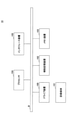
- FIG. 1 is a diagram showing an example of a system configuration according to an embodiment of the present invention.
- the resource allocation device 10 is connected to one or more client devices 30 via a network.
- the resource allocation device 10 is also connected to a plurality of service execution devices 20 constituting the service platform P1 via a network.
- the plurality of service execution devices 20 are connected to each other via a network.
- the network section between the two pairs of service execution devices 20 is referred to as a “link”.
- the service platform P1 is a computer system that provides a predetermined service (for example, a network service) by using virtual machine technology, SDN (Software Defined Network) technology, or the like.
- Each service execution device 20 is a computer on which software (in this embodiment, a virtual machine (VM (Virtual Machine))) that executes processing related to the service is operated.
- VM Virtual Machine
- the client device 30 is a computer that requests the resource allocation device 10 to allocate system resources (hereinafter, simply referred to as “resources”) required for the service.
- the resource allocation device 10 is one or more computers that execute resource allocation according to a request from the client device 30 (hereinafter referred to as “resource allocation request”) to the service platform P1.
- FIG. 2 is a diagram showing a hardware configuration example of the resource allocation device 10 according to the first embodiment.
- the resource allocation device 10 of FIG. 2 has a drive device 100, an auxiliary storage device 102, a memory device 103, a processor 104, an interface device 105, and the like, which are connected to each other by a bus B, respectively.
- the program that realizes the processing in the resource allocation device 10 is provided by a recording medium 101 such as a CD-ROM.
- a recording medium 101 such as a CD-ROM.
- the program is installed in the auxiliary storage device 102 from the recording medium 101 via the drive device 100.
- the program does not necessarily have to be installed from the recording medium 101, and may be downloaded from another computer via the network.
- the auxiliary storage device 102 stores the installed program and also stores necessary files, data, and the like.
- the memory device 103 reads the program from the auxiliary storage device 102 and stores it when there is an instruction to start the program.
- the processor 104 is a CPU or GPU (Graphics Processing Unit), or a CPU and GPU, and executes a function related to the resource allocation device 10 according to a program stored in the memory device 103.
- the interface device 105 is used as an interface for connecting to a network.
- the client device 30, the service execution device 20, and the like may also have a hardware configuration as shown in FIG.
- FIG. 3 is a diagram showing a functional configuration example of the resource allocation device 10 according to the first embodiment.
- the resource allocation device 10 includes an input reception unit 11, a measurement information acquisition unit 12, an estimated value calculation unit 13, a resource allocation unit 14, and the like. Each of these parts is realized by a process of causing the processor 104 to execute one or more programs installed in the resource allocation device 10.
- FIG. 4 is a diagram showing a functional configuration example of the service execution device 20 according to the first embodiment.
- the service execution device 20 includes a resource measurement unit 21, a time measurement unit 22, a measurement information notification unit 23, a service execution unit 24, and the like. Each of these parts is realized by a process of causing the processor of the service execution device 20 to execute one or more programs installed in the service execution device 20.
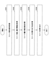
- FIG. 5 is a flowchart for explaining an example of the processing procedure executed by the resource allocation device 10 in the first embodiment.
- the input receiving unit 11 receives the resource allocation request from the client device 30.
- the resource allocation request includes, for example, information about VMs that need to be allocated (hereinafter referred to as "VM information"), a band required for communication between each VM (for example, 10 Mbps), and the like.
- VM information includes, for example, the type (that is, the function) of the execution processing of the VM, the execution order of each VM, and the like for each required VM.
- the measurement information acquisition unit 12 acquires statistical information regarding the amount of resources and the operating status or usage status of resources from each service execution device 20 and each link connecting the service execution devices 20 (S102). From each service execution device 20, for example, the amount of resources related to VM arithmetic processing such as the utilization rate of the processor (hereinafter referred to as “arithmetic resource amount”) and statistical information (hereinafter referred to as “device statistical information”). Is obtained. From each link, for example, the amount of resources related to communication between VMs such as free bandwidth (hereinafter referred to as "communication resource amount”) and statistical information (hereinafter referred to as "link statistical information”) are acquired. Examples of device statistical information and link statistical information include an average resource allocation occurrence rate, an average resource allocation time, and the like.
- the average resource allocation occurrence rate means the number of VM allocations per unit time
- the average resource allocation time means the average operating time of the VMs related to one allocation.
- the operating time means the period from the allocation of the VM to the release of the VM.
- the average resource allocation occurrence rate means the number of times a flow occurs per unit time
- the average resource allocation time means the average duration of one flow.
- the flow means a series of communications between the same communication partners.
- the average resource allocation time, average resource allocation occurrence rate, average resource usage amount, and burst traffic generation process of each resource are the same values for each resource allocation request.
- the amount of arithmetic resources and the device statistical information are measured by the resource measurement unit 21 of each service execution device 20. Further, the communication resource amount and link statistical information whose time (measurement time) at the time of measurement of the calculation resource amount and device statistical information is measured by the time measurement unit 22 of each service execution device 20 and their measurement time are, for example,. It is measured by a network device such as a switch that constitutes a link.
- the measurement information acquisition unit 12 requests each service execution device 20 and each switch to transmit the resource amount and statistical information.
- the resource measurement unit 21 of each service execution device 20 receives the request, the resource measurement unit 21 measures the amount of arithmetic resources at that time, and the time measurement unit 22 measures the time at that time.
- the measurement information notification unit 23 of each service execution device 20 is a device obtained from the measurement of the arithmetic resource amount and the measurement time of the arithmetic resource amount, and the resource amount asynchronous (for example, periodically) with the request.
- the statistical information is transmitted to the measurement information acquisition unit 12.
- each network device receives the request, it measures the amount of communication resources and the measurement time at that time.
- Each network device transmits the measurement time of the communication resource amount and the communication resource amount, and the link statistical information obtained from the measurement asynchronous to the request (for example, periodically) to the measurement information acquisition unit 12. ..
- the estimated value calculation unit 13 estimates the estimated value of the future resource amount for each resource amount (each arithmetic resource amount and each communication resource amount) based on the statistical information acquired in step S102. (Hereinafter referred to as “estimation model”), the measured value of the resource amount acquired in step S102 and the elapsed time from the measurement time of the resource amount to the scheduled resource allocation completion time are input and calculated (hereinafter referred to as "estimation model"). S103).
- the estimation model is constructed using queuing theory modeled at M / M / 100/100.
- M / M / 100/100 means a model in which the amount of resources that can be allocated is 100 and the maximum value of the amount of resources that can be allocated is 100.
- the case where the band per flow is 1 Mbps and the maximum value of the band that can be allocated is 100 Mbps corresponds to M / M / 100/100.
- the probability for each band i after t seconds is as follows. It can be calculated based on the equation.
- the value of t is the elapsed time from the measurement time of the resource amount to the scheduled resource allocation completion time.
- the estimated resource allocation completion time may be calculated by the estimated value calculation unit 13 based on, for example, past actual results.
- step S103 the estimated value calculation unit 13 t j for t, ⁇ , and ⁇ in the equation (1) for each link and for each band i in 1 Mbps increments of 0 to 100 Mbps. , ⁇ j , ⁇ j are substituted to calculate P j (t j ).
- t j is the elapsed time from the measurement time of the communication resource of the link j to the scheduled resource allocation completion time.
- ⁇ j is the average resource allocation occurrence rate of the link j.
- ⁇ j is the average resource allocation time of the link j .
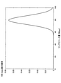
- P j (0.1) ⁇ P j (0, 0.1), ..., P j for the equation (1).
- the estimated value calculation unit 13 calculates the estimated value c j of the band after t j seconds for each link j based on the probability distribution of the band of the link j after t j seconds. As shown in the following equation (2), the expected value (mean value) of the probability distribution is calculated as the estimated value cj .
- the amount of each communication resource used for the route calculation is corrected as shown in FIG. 7, for example.
- the communication resource amount (measured value) at the time of measuring the link L1 was 60 Mbps, but the communication resource amount (estimated value) at the scheduled resource allocation completion time was corrected to 80 Mbps. ..
- the communication resource amount (measured value) at the time of measuring the link L2 was 40 Mbps, it is shown that the communication resource amount (estimated value) at the scheduled resource allocation completion time was estimated to be 30 Mbps.
- the communication resource amount (measured value) at the time of link L3 measurement was 80 Mbps, but the communication resource amount (estimated value) at the scheduled resource allocation completion time was estimated to be 50 Mbps.
- the resource allocation unit 14 calculates the service execution device 20 to which the resource is allocated, the link for allocating the communication path between the VMs, and the like, based on the estimated value calculated for each resource amount (S104).
- the resource allocation unit 14 executes resource allocation according to the resource allocation request based on the calculation result in step S104 (S105).
- steps S104 and S105 may be performed based on known techniques.
- the second embodiment will explain the differences from the first embodiment.
- the points not particularly mentioned in the second embodiment may be the same as those in the first embodiment.
- steps S102 and S103 in FIG. 5 are different from those in the first embodiment.
- step S102 the measurement information acquisition unit 12 acquires time-series data of each resource amount) (calculation resource amount, communication resource amount) from each service execution device 20 and each link.
- the time-series data is, for example, a history of the amount of resources measured periodically.
- the estimated value calculation unit 13 calculates the estimated value of the resource allocation completion time (t seconds after the measurement time) for each resource amount by using the estimation model based on the statistical processing based on the time series data.
- the estimated value calculation unit 13 acquires the measured value r1 at the measured time and the measured value r2 t seconds after the measured time for each measured time of the time series data, and (r1). , R2) Generate a pair of measured values.
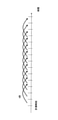
- FIG. 8 is a diagram for explaining the generation of a pair of the measured value for each measurement time and the measured value after t seconds.
- Each vertical line on the number line in FIG. 8 indicates the measurement time. If the measurement is not performed at the timing that completely matches after t seconds, the measurement value at the nearest measurement time may be acquired after t seconds. Each pair thus acquired shows the transition of the measured value in t seconds.
- the estimated value calculation unit 13 discretizes the measured values r1 and r2 of each pair. Specifically, the measured values included in the same discrete section among the preset discrete sections are discretized so as to have the same value. For example, discretization may be performed by rounding to the nearest whole number.
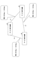
- the estimated value calculation unit 13 generates a graph showing the transition pattern from r1 to r2 based on the discretized pair group.
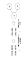
- FIG. 9 is a diagram for explaining discretization and generation of transition patterns.
- FIG. 9 shows pairs such as (10.1%, 20.3%) and (10.3%, 15.1%). When each of these measurements is discretized, for example, by rounding to the nearest whole number, each pair becomes (10%, 20%), (10%, 15%). According to these two pairs, for 10%, it can be seen that there are two transition patterns to 20% or 15% in t seconds.
- the graph showing this transition pattern is the rightmost figure of FIG.
- the common r1 transition source
- the common r2 transition destination
- the graph is referred to as a “transition graph”.
- the estimated value calculation unit 13 counts the number of occurrences of each transition pattern for each transition pattern having the same transition source node, and divides the number of occurrences by the total number of transition patterns related to the transition source node. , Calculate the probability of occurrence (probability of transition from each measured value).
- FIG. 10 is a diagram for explaining the probability of occurrence of the transition pattern.
- FIG. 10 shows that there is a possibility of transition from 10% to 20% or 15%, and the transition probabilities are 40% and 60%, respectively. That is, at this stage, the occurrence probability (transition probability) of the transition pattern corresponding to the branch is given to each branch of the transition graph.
- the transition graph in this state serves as an estimation model used in the calculation of the estimated value in the second embodiment.
- the estimated value calculation unit 13 weights the transition probability of each transition pattern having the measured value (value acquired in step S102) of the arithmetic resource as the transition source node for each arithmetic resource.
- the weighted average of the value (resource amount) of the transition destination node of the pattern is calculated as the estimated value of the resource amount at the scheduled completion time of allocation.
- step S104 in FIG. 5 may be the same as those in the first embodiment.
- one transition graph may be generated based on the time series data from all the service execution devices 20, or may be generated for each service execution device 20. In the latter case, a transition graph based on the time series data of the service execution device 20 related to the arithmetic resource may be used for calculating the estimated value of the resource amount of a certain arithmetic resource.
- the estimated value calculation unit 13 similarly calculates the estimated value of the resource amount t seconds after the measurement time for each communication resource.
- the third embodiment will explain the differences from the first embodiment.
- the points not particularly mentioned in the third embodiment may be the same as those in the first embodiment.
- the learning of the estimation model is executed by the following procedures (1) to (3) before the processing procedure of FIG. 5 is executed.
- the estimation model may use a neural network or another model.
- the estimated value calculation unit 13 uses the time-series data as training data, and causes the estimation model to learn the transition relationship of the measurement time, the amount of resources, and the statistical information. For example, the transition pattern as described in the second embodiment is learned by the estimation model. At this time, the type of execution processing may be replaced with, for example, a numerical value indicating each type.
- the estimation model is a function that inputs the time, the amount of resources, and statistical information, and outputs the estimated value of the amount of resources at the time.
- the output judged to be significant may be input to the estimation model again, and the estimation model may be retrained.
- estimation model may be learned in common with all the service execution devices 20, or may be learned for each service execution device 20.
- the processing procedure of FIG. 5 is executed in a state where the estimation model has been trained.
- step S102 the measurement information acquisition unit 12 receives from each service execution device 20 the current calculation resource, the measurement time of the calculation resource, and the statistical information of the current service execution device 20 (for example, the number of operating VMs and the execution process of each VM). Type).
- step S103 the estimated value calculation unit 13 determines the arithmetic resource acquired from the service execution device 20 and the time t seconds after the measurement time of the arithmetic resource (that is, the scheduled resource allocation completion time) for each service execution device 20. ), And the statistical information of the current service execution device 20 is input to the trained AI system, and the estimated value of the arithmetic resource at the scheduled resource allocation completion time is calculated.
- the estimation model is constructed for each service execution device 20
- the estimation value calculation unit 13 uses the estimation model learned for the service execution device 20 for each service execution device 20.
- step S104 in FIG. 5 may be the same as those in the first embodiment.
- the estimated value calculation unit 13 similarly calculates the estimated value of the resource amount t seconds after the measurement for each communication resource.
- the resource amount at the time of measurement is corrected to the estimated value at the scheduled resource allocation completion time based on the model based on the statistical information about the resource. Therefore, even if there is a time lag between the time when the resource amount is measured and the time when the resource is allocated, it is possible to increase the possibility that the resource allocation suitable for the time when the resource is allocated is executed. As a result, for example, the VM processing time and the VM communication time are reduced, and it can be expected that the service usage cost is reduced.
- the resource allocation device 10 is an example of a resource amount estimation device.
Landscapes
- Engineering & Computer Science (AREA)
- Physics & Mathematics (AREA)
- Theoretical Computer Science (AREA)
- General Physics & Mathematics (AREA)
- General Engineering & Computer Science (AREA)
- Data Mining & Analysis (AREA)
- Software Systems (AREA)
- Pure & Applied Mathematics (AREA)
- Mathematical Analysis (AREA)
- Mathematical Physics (AREA)
- Mathematical Optimization (AREA)
- Computational Mathematics (AREA)
- Quality & Reliability (AREA)
- Evolutionary Biology (AREA)
- Life Sciences & Earth Sciences (AREA)
- Bioinformatics & Computational Biology (AREA)
- Operations Research (AREA)
- Probability & Statistics with Applications (AREA)
- Computer Hardware Design (AREA)
- Algebra (AREA)
- Bioinformatics & Cheminformatics (AREA)
- Databases & Information Systems (AREA)
- Debugging And Monitoring (AREA)
- Data Exchanges In Wide-Area Networks (AREA)
Abstract
リソース量推定装置は、リソースの割り当て要求に応じ、前記リソースのリソース量の計測値、前記計測値の計測時刻、及び前記リソースに関する統計情報を取得する取得部と、将来の前記リソース量を前記統計情報に基づいて推定するモデルに、前記取得部が取得した計測値と、前記計測時刻から前記リソースの割り当て予定時刻までの経過時間とを入力して、前記割り当て予定時刻における前記リソース量の推定値を計算する計算部と、を有することで、リソースの割り当て時点に適したリソースの割り当てが実施される可能性を高める。
Description
本発明は、リソース量推定装置、リソース量推定方法及びプログラムに関する。
仮想マシン技術やSDN(Software Defined Network)技術の発達に伴い、サービス利用者が利用したいときにオンデマンドにデータ処理機能を仮想マシンやコンテナの形で提供し、機能間の通信経路を動的に設定することで、利用者にネットワークサービスを提供できるようになった。このような状況を受けて、従来、利用の多寡にかかわらず期間単位の定額料金を支払っていた低利用率ユーザがサービス利用コストを下げるためのサービスとして、リソース利用期間にのみ課金されるサーバレスコンピューティングモデルが登場した。
サーバレスコンピューティングモデルでは、オンデマンドにリソースが割り当てられ、処理終了後リソースが開放される。このため、バースト的にリソース割り当てや仮想マシン間の通信が発生する、という特徴を有する。
利用料金を低減するための要求条件として、処理時間を短縮するということが挙げられる。処理時間は、計算機能及び通信機能が利用する、サーバやリンクなどの物理演算リソースの利用率により変化する。すいている装置に計算機能及び通信機能を割り当てることで、処理時間を短縮することができる。リソース利用率の低い装置に計算/通信機能を割り当てるため、サーバレスコンピューティング処理に必要とするCPUや想定通信データ量などの要求条件とサービス用物理演算リソースとを勘案しながら、すいている装置や通信経路を導き出し、サーバレスコンピューティング処理用計算/通信機能を割り当てる技術が長年検討されてきた。
A.Fischer et al., "Virtual Network Embedding: A Survey," IEEE COMMUNICATIONS SURVEYS & TUTORIALS, VOL.15, NO.4, pp.1888-1906, FOURTH QUARTER 2013.
従来技術は、計算機能及び通信機能の割り当て箇所を計算する際、サーバやネットワークスイッチなどからデータ量やCPU利用率などのリソース情報を、割り当て箇所計算機能に集約し、集めたリソース情報をアルゴリズムなどに適用することで割り当て箇所を計算していた。
ここで、考慮すべき点は、使用しているリソース情報の鮮度、すなわち、リソース情報の計測時刻から割り当て箇所の計算時点までの経過時間の大きさである。
通常、物理リソースから割り当て箇所計算機能に測定データが届くまで、データ転送遅延や処理遅延等の影響からタイムラグが発生する。このため、割り当て箇所計算機能が計算時点で参考にするリソース情報と、当該リソース情報を送信したサーバやスイッチが当該計算時点で観測している統計情報には誤差が存在する。
このため、割り当て箇所計算機能が、得られたリソース情報をもとに最適な割り当て箇所を計算したとしても、実際に経路を割り当てる際には状況が変化し、最適解ではなくなってしまう可能性が有る。
本発明は、上記の点に鑑みてなされたものであって、リソースの割り当て時点に適したリソースの割り当てが実施される可能性を高めることを目的とする。
そこで上記課題を解決するため、リソース量推定装置は、リソースの割り当て要求に応じ、前記リソースのリソース量の計測値、前記計測値の計測時刻、及び前記リソースに関する統計情報を取得する取得部と、将来の前記リソース量を前記統計情報に基づいて推定するモデルに、前記取得部が取得した計測値と、前記計測時刻から前記リソースの割り当て予定時刻までの経過時間とを入力して、前記割り当て予定時刻における前記リソース量の推定値を計算する計算部と、を有する。
リソースの割り当て時点に適したリソースの割り当てが実施される可能性を高めることができる。
以下、図面に基づいて本発明の実施の形態を説明する。図1は、本発明の実施の形態におけるシステム構成例を示す図である。図1に示されるように、リソース割当装置10は、ネットワークを介して1以上のクライアント装置30に接続される。リソース割当装置10は、また、サービス用プラットフォームP1を構成する複数のサービス実行装置20とネットワークを介して接続される。なお、複数のサービス実行装置20は、相互にネットワークを介して接続される。以下、2対のサービス実行装置20間のネットワーク区間を「リンク」という。
サービス用プラットフォームP1は、仮想マシン技術やSDN(Software Defined Network)技術等を用いて、所定のサービス(例えば、ネットワークサービス)を提供するコンピュータシステムである。各サービス実行装置20は、サービスに関する処理を実行するソフトウェア(本実施の形態では仮想マシン(VM(Virtual Machine)))が稼働するコンピュータである。
クライアント装置30は、サービスに必要なシステムリソース(以下、単に「リソース」という。)の割当をリソース割当装置10に要求するコンピュータである。
リソース割当装置10は、クライアント装置30からの要求(以下、「リソース割当要求」という。)に応じたリソースの割当を、サービス用プラットフォームP1に対して実行する1以上のコンピュータである。
図2は、第1の実施の形態におけるリソース割当装置10のハードウェア構成例を示す図である。図2のリソース割当装置10は、それぞれバスBで相互に接続されているドライブ装置100、補助記憶装置102、メモリ装置103、プロセッサ104、及びインタフェース装置105等を有する。
リソース割当装置10での処理を実現するプログラムは、CD-ROM等の記録媒体101によって提供される。プログラムを記憶した記録媒体101がドライブ装置100にセットされると、プログラムが記録媒体101からドライブ装置100を介して補助記憶装置102にインストールされる。但し、プログラムのインストールは必ずしも記録媒体101より行う必要はなく、ネットワークを介して他のコンピュータよりダウンロードするようにしてもよい。補助記憶装置102は、インストールされたプログラムを格納すると共に、必要なファイルやデータ等を格納する。
メモリ装置103は、プログラムの起動指示があった場合に、補助記憶装置102からプログラムを読み出して格納する。プロセッサ104は、CPU若しくはGPU(Graphics Processing Unit)、又はCPU及びGPUであり、メモリ装置103に格納されたプログラムに従ってリソース割当装置10に係る機能を実行する。インタフェース装置105は、ネットワークに接続するためのインタフェースとして用いられる。
なお、クライアント装置30及びサービス実行装置20等も図2に示されるようなハードウェア構成を有してもよい。
図3は、第1の実施の形態におけるリソース割当装置10の機能構成例を示す図である。図3において、リソース割当装置10は、入力受付部11、計測情報取得部12、推定値計算部13及びリソース割当部14等を有する。これら各部は、リソース割当装置10にインストールされた1以上のプログラムが、プロセッサ104に実行させる処理により実現される。
図4は、第1の実施の形態におけるサービス実行装置20の機能構成例を示す図である。図4において、サービス実行装置20は、リソース計測部21、時刻計測部22、計測情報通知部23及びサービス実行部24等を有する。れら各部は、サービス実行装置20にインストールされた1以上のプログラムが、サービス実行装置20のプロセッサに実行させる処理により実現される。
以下、リソース割当装置10が実行する処理手順について説明する。図5は、第1の実施の形態におけるリソース割当装置10が実行する処理手順の一例を説明するためのフローチャートである。
ステップS101において、入力受付部11は、クライアント装置30からのリソース割当要求を受信する。リソース割当要求としては、例えば、割当が必要なVMに関する情報(以下、「VM情報」という。)と、各VM間の通信に必要な帯域(例えば、10Mbps)等が含まれる。VM情報には、例えば、必要なVMごとに、当該VMの実行処理のタイプ(すなわち、機能)、各VMの実行順序等が含まれる。
続いて、計測情報取得部12は、各サービス実行装置20や、サービス実行装置20間を接続する各リンクから、リソース量やリソースの稼働状況又は利用状況に関する統計情報等を取得する(S102)。各サービス実行装置20からは、例えば、プロセッサの利用率等、VMの演算処理に関連するリソース量(以下、「演算リソース量」という。)及び統計情報(以下、「装置統計情報」という。)が取得される。各リンクからは、例えば、空き帯域等、VM間の通信に関連するリソース量(以下、「通信リソース量」という。)及び統計情報(以下、「リンク統計情報」という。)が取得される。装置統計情報及びリンク統計情報の一例としては、平均リソース割り当て発生レート及び平均リソース割り当て時間等が挙げられる。
サービス実行装置20に関して、平均リソース割り当て発生レートとは、単位時間当たりのVMの割り当て回数をいい、平均リソース割り当て時間とは、1回の割り当てに係るVMの稼働時間の平均をいう。稼働時間とは、VMが割り当てられてから当該VMが解放されるまでの期間をいう。
リンクに関して、平均リソース割り当て発生レートとは、単位時間当たりのフロー(flow)の発生回数をいい、平均リソース割り当て時間とは、1フローの継続時間の平均をいう。なお、フローとは、同一の通信相手間の一連の通信をいう。
なお、本実施の形態において、各リソースの平均リソース割り当て時間、平均リソース割り当て発生レート、平均リソース利用量、バーストトラヒック発生過程は、各リソース割当要求に対して同じ値であるとする。
演算リソース量及び装置統計情報は、各サービス実行装置20のリソース計測部21によって計測される。また、演算リソース量及び装置統計情報の計測時点の時刻(計測時刻)が各サービス実行装置20の時刻計測部22によって計測される
通信リソース量及びリンク統計情報、並びにそれらの計測時刻は、例えば、リンクを構成するスイッチ等のネットワーク装置によって計測される。
通信リソース量及びリンク統計情報、並びにそれらの計測時刻は、例えば、リンクを構成するスイッチ等のネットワーク装置によって計測される。
例えば、計測情報取得部12は、各サービス実行装置20及び各スイッチに対して、リソース量及び統計情報の送信を要求する。各サービス実行装置20のリソース計測部21は、当該要求を受信すると、その時点の演算リソース量を計測し、時刻計測部22は、その時点の時刻を計測する。各サービス実行装置20の計測情報通知部23は、当該演算リソース量及び当該演算リソース量の計測時刻と、当該要求とは非同期な(例えば、定期的に)なリソース量等の計測から得られる装置統計情報とを計測情報取得部12に送信する。また、各ネットワーク装置は、当該要求を受信すると、その時点の通信リソース量及び計測時刻を計測する。各ネットワーク装置は、当該通信リソース量及び当該通信リソース量の計測時刻と、当該要求とは非同期な(例えば、定期的に)な計測から得られるリンク統計情報とを計測情報取得部12に送信する。
続いて、推定値計算部13は、各リソース量(各演算リソース量及び各通信リソース量)について、将来のリソース量の推定値を、ステップS102において取得された各統計情報に基づいて推定するモデル(以下、「推定モデル」という。)に、ステップS102において取得されたリソース量の計測値及、及び当該リソース量の計測時刻からリソースの割り当て完了予定時刻までの経過時間を入力して計算する(S103)。第1の実施の形態において、推定モデルは、M/M/100/100でモデル化される待ち行列理論が用いられて構築される。ここでは、説明を単純化するため、通信リソース量及びリンク統計情報に基づいて、リソース割当完了予定時刻の通信リソース量を推定する例について説明する。なお、M/M/100/100は、割り当て可能なリソース量が100であり、割り当て可能なリソース量の最大値が100であるモデルを意味する。例えば、1フロー当たりの帯域が1Mbpsであり、割り当て可能な帯域の最大値が100Mbpsである場合が、M/M/100/100に該当する。
ここで、ステップS102において取得された通信リソース量がB(Mbps)、平均リソース割り当て発生レートがλ、平均リソース割り当て時間がμである場合、t秒後の帯域iごとの確率は、以下の状態方程式に基づいて算出可能である。なお、tの値は、リソース量の計測時刻からリソース割当完了予定時刻まで経過時間である。当該リソース割当完了予定時刻は、例えば、過去の実績等に基づいて、推定値計算部13が計算すればよい。
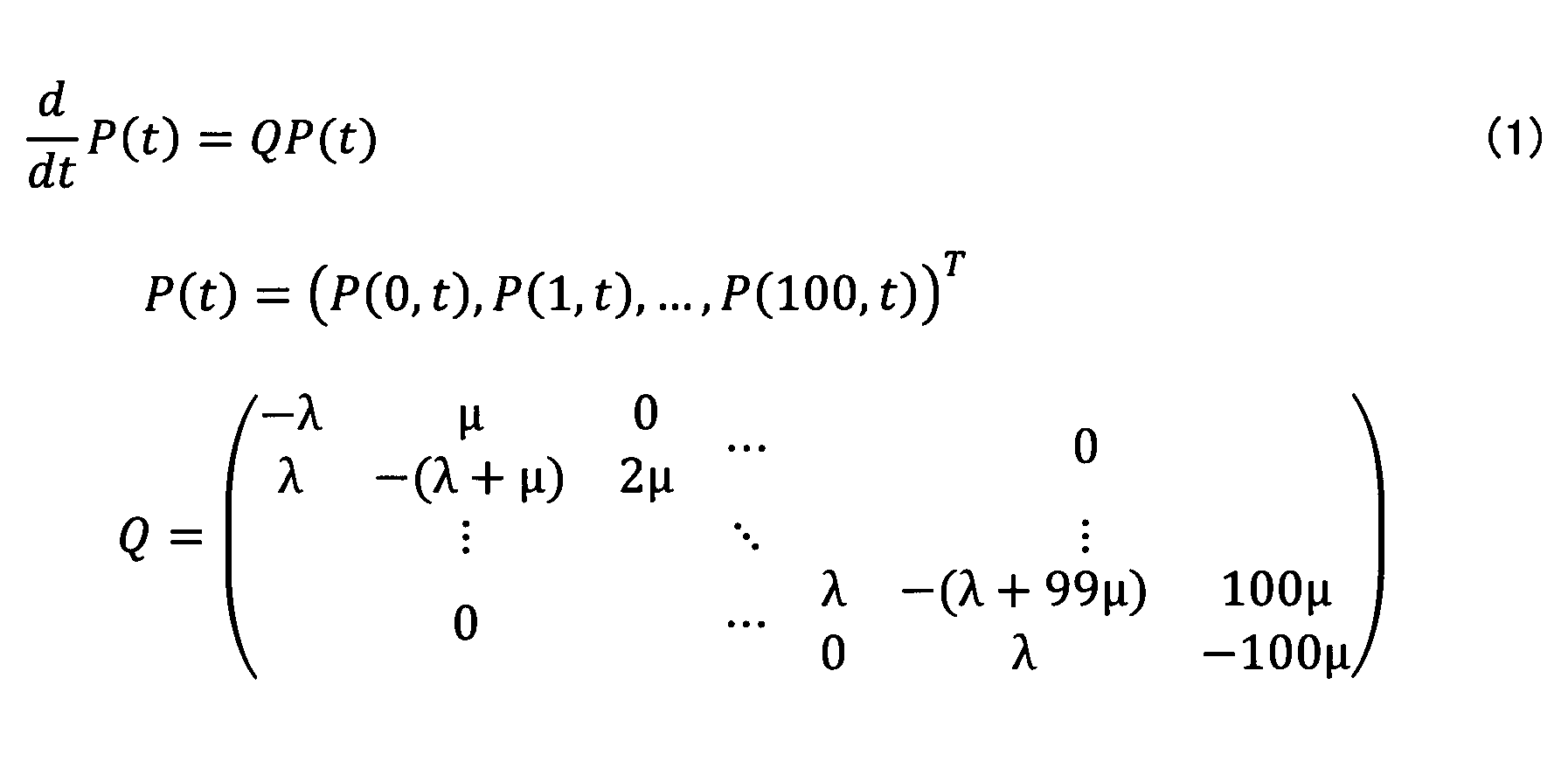
P(B,0)=1
P(i,0)=0(i≠B)
Q:状態遷移行列
したがって、ステップS103において、推定値計算部13は、リンクごとに、0~100Mbpsの1Mbps刻みの帯域iごとに、式(1)のt、λ、μに対して、tj、λj、μjを代入することで、Pj(tj)を計算する。なお、tjは、リンクjの通信リソースの計測時刻からリソース割当完了予定時刻までの経過時間である。λjは、リンクjの平均リソース割り当て発生レートである。μjは、リンクjの平均リソース割り当て時間である。Pj(tj)は、リンクjのtj秒後における各帯域の確率分布である。例えば、tj=100msecとした場合、式(1)は、図6に示されるような確率分布を示す。
すなわち、tj=100msecであるリンクjについて、推定値計算部13は、式(1)について、Pj(0.1)={Pj(0,0.1),...,Pj(100,0.1)}を計算することで、計測時刻から100msec後の帯域の確率分布を得る。
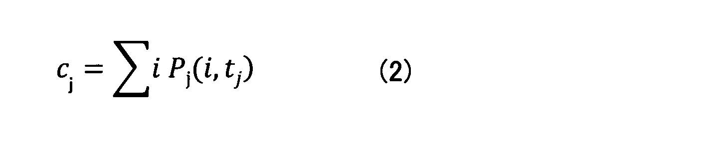
続いて、推定値計算部13は、各リンクjについて、当該リンクjの帯域のtj秒後の確率分布に基づいて、tj秒後の帯域の推定値cjを計算する。以下の式(2)に示される通り、確率分布の期待値(平均値)が推定値cjとして算出される。
なお、上記では、通信リソース量について述べたが、各演算リソース量についても同様の考え方で補正する(リソース割当完了予定時刻での推定値を算出する)ことができる。
続いて、リソース割当部14は、各リソース量について算出された推定値に基づいて、リソースの割り当て先とするサービス実行装置20や、VM間の通信経路を割り当てるリンク等を計算する(S104)。
続いて、リソース割当部14は、ステップS104の計算結果に基づき、リソース割当要求に応じたリソースの割り当てを実行する(S105)。
なお、ステップS104及びS105、公知技術に基づいて行われればよい。
次に、第2の実施の形態について説明する。第2の実施の形態では第1の実施の形態と異なる点について説明する。第2の実施の形態において特に言及されない点については、第1の実施の形態と同様でもよい。
第2の実施の形態では、図5のステップS102及びS103の内容が第1の実施の形態と異なる。
ステップS102において、計測情報取得部12は、各サービス実行装置20及び各リンクから、それぞれのリソース量)(演算リソース量、通信リソース量)の時系列データを取得する。当該時系列データは、例えば、定期的に計測されたリソース量の履歴である。
続くステップS103において、推定値計算部13は、各リソース量について、時系列データに基づく統計処理に基づく推定モデルを用いてリソース割当完了時刻(計測時刻からt秒後)の推定値を計算する。
当該統計処理の詳細について説明する。ここでは、演算リソース量(CPU利用率)についての推定値の計算方法を説明する。
まず、推定値計算部13は、時系列データの各計測値の計測時刻ごとに、当該計測時刻の計測値r1と、当該計測時刻からt秒後の計測値r2とを取得して、(r1,r2)の計測値のペアを生成する。
図8は、計測時刻ごとの計測値とt秒後の計測値とのペアの生成を説明するための図である。図8の数直線上の各垂直線は、計測時刻を示す。なお、t秒後に完全に一致するタイミングで計測が行われていない場合には、t秒後に最も近い計測時刻の計測値が取得されればよい。このように取得される各ペアは、t秒間における計測値の遷移を示す。
続いて、推定値計算部13は、各ペアの計測値r1及びr2を離散化する。具体的には、予め設定された各離散区間のうち同一の離散区間に含まれる計測値が同一の値になるように離散化される。例えば、小数点以下の四捨五入によって離散化が行われてもよい。推定値計算部13は、離散化されたペア群に基づいて、r1からr2への遷移パターンを示すグラフを生成する。
図9は、離散化及び遷移パターンの生成を説明するための図である。図9には、(10.1%,20.3%)及び(10.3%,15.1%)等のペアが示されている。これらの各計測値が、例えば、小数点以下の四捨五入によって離散化されると、各ペアは、(10%,20%)、(10%,15%)となる。この2つのペアによれば、10%については、t秒間において20%又は15%への2つの遷移パターンが存在することが分かる。この遷移パターンを示すグラフが図9の右端の図である。当該グラフでは、共通のr1(遷移元)は、同一のノード(遷移元ノード)に統合され、共通のr2(遷移先)は、同一のノード(遷移先ノード)に統合される。以下、当該グラフを「遷移グラフ」という。
続いて、推定値計算部13は、遷移元ノードを同じくする遷移パターンごとに、各遷移パターンの発生回数をカウントし、当該発生回数を当該遷移元ノードに係る遷移パターンの総数で除することで、発生確率(各計測値からの遷移確率)を算出する。
図10は、遷移パターンの発生確率を説明するための図である。図10には、10%からは20%又は15%へ遷移する可能性があり、それぞれの遷移確率は40%、60%であることが示されている。すなわち、この段階では、遷移グラフの各枝に当該枝に対応する遷移パターンの発生確率(遷移確率)が付与される。この状態の遷移グラフが、第2の実施の形態において推定値の計算に用いられる推定モデルとなる。
続いて、推定値計算部13は、各演算リソースについて、当該演算リソースの計測値(ステップS102で取得された値)を遷移元ノードとする各遷移パターンの遷移確率を重みとする、当該各遷移パターンの遷移先ノードの値(リソース量)の加重平均を、割当完了予定時刻の当該リソース量の推定値として計算する。
図5のステップS104以降は、第1の実施の形態と同様でよい。
なお、遷移グラフは、全てのサービス実行装置20からの時系列データに基づいて1つ生成されてもよいし、サービス実行装置20ごとに生成されてもよい。後者の場合、或る演算リソースのリソース量の推定値の計算には、当該演算リソースに係るサービス実行装置20の時系列データに基づく遷移グラフが用いられればよい。
また、上記では、便宜上、演算リソースについて述べたが、推定値計算部13は、各通信リソースについても同様に、計測時刻からt秒後のリソース量の推定値を計算する。
次に、第3の実施の形態について説明する。第3の実施の形態では第1の実施の形態と異なる点について説明する。第3の実施の形態において特に言及されない点については、第1の実施の形態と同様でもよい。
第3の実施の形態では、推定モデルとして機械学習に基づくモデルが用いられる例について説明する。なお、第3の実施の形態においては、便宜上、演算リソースを対象として説明する。
第3の実施の形態では、図5の処理手順が実行される前に推定モデルの学習が以下の(1)~(3)の手順で実行される。推定モデルは、ニューラルネットワークを用いたものでもよいし、他のモデルを用いたものでもよい。
(1)学習データとして、各サービス実行装置20のリソース計測部21が定期的な計測時刻において記録した、当該計測時刻、演算リソース量、当該リソース量に係るリソースを利用するソフトウェア(VM)に関する統計情報(例えば、稼働VM数、各VMの実行処理のタイプ)を各サービス実行装置20から計測情報取得部12が取得する。すなわち、各計測時点の計測時刻、リソース量及び統計情報を含む時系列データが取得される。
(2)推定値計算部13は、当該時系列データを学習データとして、計測時刻、リソース量及び統計情報の遷移関係を推定モデルに学習させる。例えば、第2の実施の形態において説明したような遷移パターンが推定モデルによって学習される。この際、実行処理のタイプは、例えば、各タイプを示す数値に置換されればよい。なお、当該推定モデルは、時刻、リソース量及び統計情報を入力とし、当該時刻のリソース量の推定値を出力する関数である。
(3)推定モデルによる出力を技術者が識別したうえで、有意と判断した出力を再度推定モデルに入力して、推定モデルが再学習されてもよい。
なお、推定モデルは、全てのサービス実行装置20に対して共通なものが学習されてよいし、サービス実行装置20ごとに学習が行われてもよい。
第3の実施の形態では、推定モデルが学習済みである状態において、図5の処理手順が実行される。
ステップS102において、計測情報取得部12は、各サービス実行装置20から現時点の演算リソース、当該演算リソースの計測時刻及び現時点のサービス実行装置20の統計情報(例えば、稼働VM数、各VMの実行処理のタイプ)を取得する。
ステップS103において、推定値計算部13は、サービス実行装置20ごとに、当該サービス実行装置20から取得された演算リソース、当該演算リソースの計測時刻からt秒後の時刻(すなわち、リソース割当完了予定時刻)、及び現時点のサービス実行装置20の統計情報を学習済みのAIシステムへ入力して、リソース割当完了予定時刻の当該演算リソースの推定値を計算する。なお、推定モデルがサービス実行装置20ごとに構築されている場合、推定値計算部13は、サービス実行装置20ごとに当該サービス実行装置20に関して学習済みの推定モデルを利用する。
図5のステップS104以降は、第1の実施の形態と同様でよい。
なお、上記では、便宜上、演算リソースについて述べたが、推定値計算部13は、各通信リソースについても同様に計測時からt秒後のリソース量の推定値を計算する。
上述したように、上記各実施の形態によれば、リソースに関する統計情報に基づくモデルに基づいて、計測時点のリソース量がリソース割当完了予定時刻における推定値に補正される。したがって、リソース量の計測時点とリソースの割り当て時点との間にタイムラグが存在する場合であっても、リソースの割り当て時点に適したリソースの割り当てが実施される可能性を高めることができる。その結果、例えば、VMの処理時間やVM通信時間が低減され、サービス利用コストの低減を期待することができる。
なお、上記各実施の形態において、リソース割当装置10は、リソース量推定装置の一例である。
以上、本発明の実施の形態について詳述したが、本発明は斯かる特定の実施形態に限定されるものではなく、請求の範囲に記載された本発明の要旨の範囲内において、種々の変形・変更が可能である。
10 リソース割当装置
11 入力受付部
12 計測情報取得部
13 推定値計算部
14 リソース割当部
20 サービス実行装置
21 リソース計測部
22 時刻計測部
23 計測情報通知部
24 サービス実行部
30 クライアント装置
100 ドライブ装置
101 記録媒体
102 補助記憶装置
103 メモリ装置
104 プロセッサ
105 インタフェース装置
B バス
P1 サービス用プラットフォーム
11 入力受付部
12 計測情報取得部
13 推定値計算部
14 リソース割当部
20 サービス実行装置
21 リソース計測部
22 時刻計測部
23 計測情報通知部
24 サービス実行部
30 クライアント装置
100 ドライブ装置
101 記録媒体
102 補助記憶装置
103 メモリ装置
104 プロセッサ
105 インタフェース装置
B バス
P1 サービス用プラットフォーム
Claims (7)
- リソースの割り当て要求に応じ、前記リソースのリソース量の計測値、前記計測値の計測時刻、及び前記リソースに関する統計情報を取得する取得部と、
将来の前記リソース量を前記統計情報に基づいて推定するモデルに、前記取得部が取得した計測値と、前記計測時刻から前記リソースの割り当て予定時刻までの経過時間とを入力して、前記割り当て予定時刻における前記リソース量の推定値を計算する計算部と、
を有することを特徴とするリソース量推定装置。 - 前記モデルは、待ち行列理論、統計処理、又は機械学習を用いたモデルである。
ことを特徴とする請求項1記載のリソース量推定装置。 - 前記統計情報は、前記リソースに関する平均リソース割り当て発生レート及び平均リソース割り当て時間、又は前記リソース量の時系列データを含む、
ことを特徴とする請求項1又は2記載のリソース量推定装置。 - リソースの割り当て要求に応じ、前記リソースのリソース量の計測値、前記計測値の計測時刻、及び前記リソースに関する統計情報を取得する取得手順と、
将来の前記リソース量を前記統計情報に基づいて推定するモデルに、前記取得手順が取得した計測値と、前記計測時刻から前記リソースの割り当て予定時刻までの経過時間とを入力して、前記割り当て予定時刻における前記リソース量の推定値を計算する計算手順と、
をコンピュータが実行することを特徴とするリソース量推定方法。 - 前記モデルは、待ち行列理論、統計処理、又は機械学習を用いたモデルである。
ことを特徴とする請求項4記載のリソース量推定方法。 - 前記統計情報は、前記リソースに関する平均リソース割り当て発生レート及び平均リソース割り当て時間、又は前記リソース量の時系列データを含む、
ことを特徴とする請求項4又は5記載のリソース量推定方法。 - 請求項4乃至6いずれか一項記載のリソース量推定方法をコンピュータに実行させることを特徴とするプログラム。
Priority Applications (3)
| Application Number | Priority Date | Filing Date | Title |
|---|---|---|---|
| PCT/JP2020/032029 WO2022044121A1 (ja) | 2020-08-25 | 2020-08-25 | リソース量推定装置、リソース量推定方法及びプログラム |
| US18/006,778 US20230305902A1 (en) | 2020-08-25 | 2020-08-25 | Resource quantity estimation apparatus, resource quantity estimation method and program |
| JP2022544933A JP7439938B2 (ja) | 2020-08-25 | 2020-08-25 | リソース量推定装置、リソース量推定方法及びプログラム |
Applications Claiming Priority (1)
| Application Number | Priority Date | Filing Date | Title |
|---|---|---|---|
| PCT/JP2020/032029 WO2022044121A1 (ja) | 2020-08-25 | 2020-08-25 | リソース量推定装置、リソース量推定方法及びプログラム |
Publications (1)
| Publication Number | Publication Date |
|---|---|
| WO2022044121A1 true WO2022044121A1 (ja) | 2022-03-03 |
Family
ID=80354878
Family Applications (1)
| Application Number | Title | Priority Date | Filing Date |
|---|---|---|---|
| PCT/JP2020/032029 Ceased WO2022044121A1 (ja) | 2020-08-25 | 2020-08-25 | リソース量推定装置、リソース量推定方法及びプログラム |
Country Status (3)
| Country | Link |
|---|---|
| US (1) | US20230305902A1 (ja) |
| JP (1) | JP7439938B2 (ja) |
| WO (1) | WO2022044121A1 (ja) |
Cited By (2)
| Publication number | Priority date | Publication date | Assignee | Title |
|---|---|---|---|---|
| JP7233664B1 (ja) | 2022-06-10 | 2023-03-07 | 17Live株式会社 | 品質予測のためのシステム、方法、及びコンピュータ可読媒体 |
| JP2024035626A (ja) * | 2022-09-02 | 2024-03-14 | 横河電機株式会社 | 情報提供装置、情報提供方法、情報提供プログラム、情報管理装置および情報管理プログラム |
Citations (2)
| Publication number | Priority date | Publication date | Assignee | Title |
|---|---|---|---|---|
| JP2015162701A (ja) * | 2014-02-26 | 2015-09-07 | 京セラ株式会社 | 携帯端末及びその無線通信制御方法 |
| JP2018026050A (ja) * | 2016-08-12 | 2018-02-15 | 富士通株式会社 | 並列処理装置、ジョブ管理プログラムおよびジョブ管理方法 |
Family Cites Families (2)
| Publication number | Priority date | Publication date | Assignee | Title |
|---|---|---|---|---|
| US9870269B1 (en) * | 2013-09-05 | 2018-01-16 | Amazon Technologies, Inc. | Job allocation in a clustered environment |
| US11656912B1 (en) * | 2020-02-10 | 2023-05-23 | Amazon Technologies, Inc. | Enabling conditional computing resource terminations based on forecasted capacity availability |
-
2020
- 2020-08-25 US US18/006,778 patent/US20230305902A1/en not_active Abandoned
- 2020-08-25 JP JP2022544933A patent/JP7439938B2/ja active Active
- 2020-08-25 WO PCT/JP2020/032029 patent/WO2022044121A1/ja not_active Ceased
Patent Citations (2)
| Publication number | Priority date | Publication date | Assignee | Title |
|---|---|---|---|---|
| JP2015162701A (ja) * | 2014-02-26 | 2015-09-07 | 京セラ株式会社 | 携帯端末及びその無線通信制御方法 |
| JP2018026050A (ja) * | 2016-08-12 | 2018-02-15 | 富士通株式会社 | 並列処理装置、ジョブ管理プログラムおよびジョブ管理方法 |
Cited By (4)
| Publication number | Priority date | Publication date | Assignee | Title |
|---|---|---|---|---|
| JP7233664B1 (ja) | 2022-06-10 | 2023-03-07 | 17Live株式会社 | 品質予測のためのシステム、方法、及びコンピュータ可読媒体 |
| JP2023180842A (ja) * | 2022-06-10 | 2023-12-21 | 17Live株式会社 | 品質予測のためのシステム、方法、及びコンピュータ可読媒体 |
| JP2024035626A (ja) * | 2022-09-02 | 2024-03-14 | 横河電機株式会社 | 情報提供装置、情報提供方法、情報提供プログラム、情報管理装置および情報管理プログラム |
| JP7779218B2 (ja) | 2022-09-02 | 2025-12-03 | 横河電機株式会社 | 情報提供装置、情報提供方法、情報提供プログラム、情報管理装置および情報管理プログラム |
Also Published As
| Publication number | Publication date |
|---|---|
| US20230305902A1 (en) | 2023-09-28 |
| JPWO2022044121A1 (ja) | 2022-03-03 |
| JP7439938B2 (ja) | 2024-02-28 |
Similar Documents
| Publication | Publication Date | Title |
|---|---|---|
| CN114930293B (zh) | 预测性自动扩展和资源优化 | |
| Bhattacharjee et al. | Barista: Efficient and scalable serverless serving system for deep learning prediction services | |
| Zhang et al. | Guaranteeing deadlines for inter-datacenter transfers | |
| US12333348B2 (en) | Allocating computing resources for deferrable virtual machines | |
| CN104951372B (zh) | 一种基于预测的Map/Reduce数据处理平台内存资源动态分配方法 | |
| US20210058453A1 (en) | Systems and methods for spike detection and load balancing resource management | |
| CN119376890A (zh) | 任务资源调度方法、装置、设备及存储介质 | |
| CN111381950A (zh) | 一种面向边缘计算环境基于多副本的任务调度方法和系统 | |
| US11526784B2 (en) | Real-time server capacity optimization tool using maximum predicted value of resource utilization determined based on historica data and confidence interval | |
| US11977761B2 (en) | Predictive allocation of ephemeral containers for cloud computing services | |
| CN109165093A (zh) | 一种计算节点集群弹性分配系统及方法 | |
| WO2016119412A1 (zh) | 一种云平台上的资源伸缩方法和一种云平台 | |
| KR102336297B1 (ko) | 공유 gpu 클러스터를 위한 분산 딥러닝 작업 스케줄링 방법 및 이를 기록한 컴퓨터 판독 가능 기록매체 | |
| Rac et al. | Cost-aware service placement and scheduling in the edge-cloud continuum | |
| WO2020206699A1 (en) | Predicting virtual machine allocation failures on server node clusters | |
| JV et al. | HAS: Hybrid auto-scaler for resource scaling in cloud environment | |
| JP7439938B2 (ja) | リソース量推定装置、リソース量推定方法及びプログラム | |
| CN100473021C (zh) | 用于通过调节网络控制进行自动的系统管理的系统和方法 | |
| CN119806839A (zh) | 一种资源分配方法及电子设备 | |
| Zhang et al. | Grandet: cost-aware traffic scheduling without prior knowledge in SD-WAN | |
| CN117321972A (zh) | 用于智能基础设施协调的基于机器学习的应用规模调整引擎 | |
| IL301738A (en) | Predictive block storage size allocation for cloud storage | |
| Lin et al. | A model-based scalability optimization methodology for cloud applications | |
| US11886901B2 (en) | VM performance guaranteeing system and VM performance guaranteeing method | |
| CN119739497A (zh) | 一种基于混合式架构的分布式资源管理和调度方法 |
Legal Events
| Date | Code | Title | Description |
|---|---|---|---|
| 121 | Ep: the epo has been informed by wipo that ep was designated in this application |
Ref document number: 20951375 Country of ref document: EP Kind code of ref document: A1 |
|
| ENP | Entry into the national phase |
Ref document number: 2022544933 Country of ref document: JP Kind code of ref document: A |
|
| NENP | Non-entry into the national phase |
Ref country code: DE |
|
| 122 | Ep: pct application non-entry in european phase |
Ref document number: 20951375 Country of ref document: EP Kind code of ref document: A1 |