WO2022038898A1 - 接合体、保持装置、および、静電チャック - Google Patents
接合体、保持装置、および、静電チャック Download PDFInfo
- Publication number
- WO2022038898A1 WO2022038898A1 PCT/JP2021/024111 JP2021024111W WO2022038898A1 WO 2022038898 A1 WO2022038898 A1 WO 2022038898A1 JP 2021024111 W JP2021024111 W JP 2021024111W WO 2022038898 A1 WO2022038898 A1 WO 2022038898A1
- Authority
- WO
- WIPO (PCT)
- Prior art keywords
- hole
- metal layer
- metal
- tubular member
- electrostatic chuck
- Prior art date
- Legal status (The legal status is an assumption and is not a legal conclusion. Google has not performed a legal analysis and makes no representation as to the accuracy of the status listed.)
- Ceased
Links
Images


Classifications
-
- C—CHEMISTRY; METALLURGY
- C04—CEMENTS; CONCRETE; ARTIFICIAL STONE; CERAMICS; REFRACTORIES
- C04B—LIME, MAGNESIA; SLAG; CEMENTS; COMPOSITIONS THEREOF, e.g. MORTARS, CONCRETE OR LIKE BUILDING MATERIALS; ARTIFICIAL STONE; CERAMICS; REFRACTORIES; TREATMENT OF NATURAL STONE
- C04B37/00—Joining burned ceramic articles with other burned ceramic articles or other articles by heating
- C04B37/02—Joining burned ceramic articles with other burned ceramic articles or other articles by heating with metallic articles
- C04B37/023—Joining burned ceramic articles with other burned ceramic articles or other articles by heating with metallic articles characterised by the interlayer used
- C04B37/026—Joining burned ceramic articles with other burned ceramic articles or other articles by heating with metallic articles characterised by the interlayer used consisting of metals or metal salts
-
- H—ELECTRICITY
- H10—SEMICONDUCTOR DEVICES; ELECTRIC SOLID-STATE DEVICES NOT OTHERWISE PROVIDED FOR
- H10P—GENERIC PROCESSES OR APPARATUS FOR THE MANUFACTURE OR TREATMENT OF DEVICES COVERED BY CLASS H10
- H10P72/00—Handling or holding of wafers, substrates or devices during manufacture or treatment thereof
- H10P72/70—Handling or holding of wafers, substrates or devices during manufacture or treatment thereof for supporting or gripping
- H10P72/72—Handling or holding of wafers, substrates or devices during manufacture or treatment thereof for supporting or gripping using electrostatic chucks
-
- H—ELECTRICITY
- H10—SEMICONDUCTOR DEVICES; ELECTRIC SOLID-STATE DEVICES NOT OTHERWISE PROVIDED FOR
- H10P—GENERIC PROCESSES OR APPARATUS FOR THE MANUFACTURE OR TREATMENT OF DEVICES COVERED BY CLASS H10
- H10P72/00—Handling or holding of wafers, substrates or devices during manufacture or treatment thereof
- H10P72/70—Handling or holding of wafers, substrates or devices during manufacture or treatment thereof for supporting or gripping
-
- C—CHEMISTRY; METALLURGY
- C04—CEMENTS; CONCRETE; ARTIFICIAL STONE; CERAMICS; REFRACTORIES
- C04B—LIME, MAGNESIA; SLAG; CEMENTS; COMPOSITIONS THEREOF, e.g. MORTARS, CONCRETE OR LIKE BUILDING MATERIALS; ARTIFICIAL STONE; CERAMICS; REFRACTORIES; TREATMENT OF NATURAL STONE
- C04B2237/00—Aspects relating to ceramic laminates or to joining of ceramic articles with other articles by heating
- C04B2237/02—Aspects relating to interlayers, e.g. used to join ceramic articles with other articles by heating
- C04B2237/12—Metallic interlayers
-
- C—CHEMISTRY; METALLURGY
- C04—CEMENTS; CONCRETE; ARTIFICIAL STONE; CERAMICS; REFRACTORIES
- C04B—LIME, MAGNESIA; SLAG; CEMENTS; COMPOSITIONS THEREOF, e.g. MORTARS, CONCRETE OR LIKE BUILDING MATERIALS; ARTIFICIAL STONE; CERAMICS; REFRACTORIES; TREATMENT OF NATURAL STONE
- C04B2237/00—Aspects relating to ceramic laminates or to joining of ceramic articles with other articles by heating
- C04B2237/30—Composition of layers of ceramic laminates or of ceramic or metallic articles to be joined by heating, e.g. Si substrates
- C04B2237/32—Ceramic
- C04B2237/34—Oxidic
- C04B2237/343—Alumina or aluminates
-
- C—CHEMISTRY; METALLURGY
- C04—CEMENTS; CONCRETE; ARTIFICIAL STONE; CERAMICS; REFRACTORIES
- C04B—LIME, MAGNESIA; SLAG; CEMENTS; COMPOSITIONS THEREOF, e.g. MORTARS, CONCRETE OR LIKE BUILDING MATERIALS; ARTIFICIAL STONE; CERAMICS; REFRACTORIES; TREATMENT OF NATURAL STONE
- C04B2237/00—Aspects relating to ceramic laminates or to joining of ceramic articles with other articles by heating
- C04B2237/30—Composition of layers of ceramic laminates or of ceramic or metallic articles to be joined by heating, e.g. Si substrates
- C04B2237/32—Ceramic
- C04B2237/36—Non-oxidic
- C04B2237/366—Aluminium nitride
-
- C—CHEMISTRY; METALLURGY
- C04—CEMENTS; CONCRETE; ARTIFICIAL STONE; CERAMICS; REFRACTORIES
- C04B—LIME, MAGNESIA; SLAG; CEMENTS; COMPOSITIONS THEREOF, e.g. MORTARS, CONCRETE OR LIKE BUILDING MATERIALS; ARTIFICIAL STONE; CERAMICS; REFRACTORIES; TREATMENT OF NATURAL STONE
- C04B2237/00—Aspects relating to ceramic laminates or to joining of ceramic articles with other articles by heating
- C04B2237/30—Composition of layers of ceramic laminates or of ceramic or metallic articles to be joined by heating, e.g. Si substrates
- C04B2237/40—Metallic
- C04B2237/403—Refractory metals
-
- C—CHEMISTRY; METALLURGY
- C04—CEMENTS; CONCRETE; ARTIFICIAL STONE; CERAMICS; REFRACTORIES
- C04B—LIME, MAGNESIA; SLAG; CEMENTS; COMPOSITIONS THEREOF, e.g. MORTARS, CONCRETE OR LIKE BUILDING MATERIALS; ARTIFICIAL STONE; CERAMICS; REFRACTORIES; TREATMENT OF NATURAL STONE
- C04B2237/00—Aspects relating to ceramic laminates or to joining of ceramic articles with other articles by heating
- C04B2237/50—Processing aspects relating to ceramic laminates or to the joining of ceramic articles with other articles by heating
- C04B2237/59—Aspects relating to the structure of the interlayer
- C04B2237/597—Aspects relating to the structure of the interlayer whereby the interlayer is continuous but porous, e.g. containing hollow or porous particles, macro- or micropores or cracks
-
- C—CHEMISTRY; METALLURGY
- C04—CEMENTS; CONCRETE; ARTIFICIAL STONE; CERAMICS; REFRACTORIES
- C04B—LIME, MAGNESIA; SLAG; CEMENTS; COMPOSITIONS THEREOF, e.g. MORTARS, CONCRETE OR LIKE BUILDING MATERIALS; ARTIFICIAL STONE; CERAMICS; REFRACTORIES; TREATMENT OF NATURAL STONE
- C04B2237/00—Aspects relating to ceramic laminates or to joining of ceramic articles with other articles by heating
- C04B2237/50—Processing aspects relating to ceramic laminates or to the joining of ceramic articles with other articles by heating
- C04B2237/62—Forming laminates or joined articles comprising holes, channels or other types of openings
-
- C—CHEMISTRY; METALLURGY
- C04—CEMENTS; CONCRETE; ARTIFICIAL STONE; CERAMICS; REFRACTORIES
- C04B—LIME, MAGNESIA; SLAG; CEMENTS; COMPOSITIONS THEREOF, e.g. MORTARS, CONCRETE OR LIKE BUILDING MATERIALS; ARTIFICIAL STONE; CERAMICS; REFRACTORIES; TREATMENT OF NATURAL STONE
- C04B2237/00—Aspects relating to ceramic laminates or to joining of ceramic articles with other articles by heating
- C04B2237/50—Processing aspects relating to ceramic laminates or to the joining of ceramic articles with other articles by heating
- C04B2237/76—Forming laminates or joined articles comprising at least one member in the form other than a sheet or disc, e.g. two tubes or a tube and a sheet or disc
- C04B2237/765—Forming laminates or joined articles comprising at least one member in the form other than a sheet or disc, e.g. two tubes or a tube and a sheet or disc at least one member being a tube
Definitions
- the present invention relates to a bonded body, a holding device, and an electrostatic chuck.
- a holding device for holding a wafer includes a ceramic member having a mounting surface on which the wafer is placed, a metal member for cooling the wafer, and a joint portion for joining the ceramic member and the metal member. It has a bonded body (for example, Patent Document 1).
- a metal layer may be placed at the joint of the joint in order to relieve the stress due to the difference in thermal expansion between the ceramic member and the metal member.
- the fluid in the through hole leaks from the inside of the through hole to the inside of the metal layer, or the fluid outside the holding device penetrates through the hole in the metal layer. There was a risk of flowing into the hole. In addition, debris from the metal layer may fall into the through hole.
- the present invention has been made to solve at least a part of the above-mentioned problems, and can be realized as the following forms.
- a bonded body in which the first member and the second member are joined via a joint portion including a metal layer having a plurality of holes communicating with each other.
- a metal layer having a plurality of holes communicating with each other.
- through holes communicating with each other are formed in the first member and the metal layer, respectively, and between the inside of the through holes formed in the metal layer and the inside of the metal layer, Cylindrical members are arranged.
- the metal layer included in the joint portion has a plurality of holes communicating with each other, and the metal layer is formed with through holes communicating with the through holes formed in the first member.
- a cylindrical member is arranged between the inside of the through hole of the metal layer and the inside of the metal layer.
- the second member may be formed with a through hole communicating with the through hole formed in the first member and the metal layer, respectively.
- the through holes formed in the first member and the metal layer, respectively, and the through holes formed in the second member communicate with each other.
- the tubular member suppresses the leakage of the fluid in the through hole to the metal layer and the inflow of the fluid inside the metal layer into the through hole.
- the change in the flow rate of the fluid flowing through the through hole of the second member with respect to the flow rate of the fluid flowing through the through hole of the second member becomes small. As a result, the fluid can be stably supplied from the first member side to the second member side or from the second member side to the first member side with the joint body interposed therebetween.
- one end of the tubular member is arranged inside a through hole formed in the first member, and the other end of the tubular member is the first. It may be arranged inside the through hole formed in the two members. According to this configuration, one end of the tubular member is arranged inside the through hole of the first member, and the other end is arranged inside the through hole of the second member.
- a bellows portion may be formed on the outer periphery of the tubular member in the circumferential direction.
- a bellows portion is formed on the outer periphery of the tubular member over the circumferential direction.
- the tubular member may be formed of the same material as the metal layer.
- the tubular member is made of the same material as the metal layer.
- the joint portion is formed of two types of materials, that is, the material of the tubular member and the metal layer, and the material of the brazing material. Therefore, the tubular member, the metal layer, and the brazing material are made of different materials. Compared to the case where it is formed, the composition of the joint is uniform regardless of the site. Therefore, the difference in thermal stress between the portions is less likely to occur at the joint portion, and the breakage of the joint body can be further suppressed.
- the cross section perpendicular to the axial direction of the tubular member may be circular.
- the tubular member is formed so that the cross section perpendicular to the axial direction has a circular shape.
- the tubular member is less likely to be deformed by the force acting from the direction intersecting the axis, so that the fluid moves between the through hole and the metal layer and the metal layer debris falls into the through hole. It can be suppressed.
- a holding device includes the above-mentioned joint body, and the second member includes a mounting surface on which a holding object is placed.
- the through holes formed in the first member and the metal layer and the through holes of the second member communicate with each other, the change in the flow rate of the fluid flowing through these through holes is suppressed. Therefore, the fluid can be stably supplied between the holding object and the mounting surface. Further, since the falling of the metal layer debris into the through hole is suppressed, it is possible to suppress the contamination of the object to be retained by the metal layer debris. As a result, the yield of the product can be improved.
- an electrostatic chuck includes the above-mentioned holding device, and the second member has an electrostatic adsorption electrode inside.
- the joint is formed with through holes for supplying fluid to the mounting surface.
- the tubular member arranged between the inside of the through hole of the metal layer and the inside of the metal layer can suppress the blockage of the through hole due to the leakage of the bonding material to the through hole. can.
- the falling of the metal layer debris into the through hole is suppressed, so that contamination by the metal layer debris can be suppressed. Therefore, it is possible to improve the yield of products manufactured by using the electrostatic chuck.
- the present invention can be realized in various aspects, for example, in the form of a device including a bonded body, a method for manufacturing a bonded body and a holding device, and the like.
- FIG. 1 is a perspective view showing the appearance of the electrostatic chuck 1 of the first embodiment.
- FIG. 2 is an overall cross-sectional view of the electrostatic chuck 1.
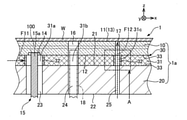
- FIG. 3 is a partial cross-sectional view of the electrostatic chuck 1.
- the electrostatic chuck 1 of the first embodiment is a holding device that holds the wafer W by adsorbing it by electrostatic attraction, and is provided in, for example, an etching device.
- the electrostatic chuck 1 includes a ceramic member 10, an electrode terminal 15, a lift pin 18, a metal member 20, and a joint portion 30. In the electrostatic chuck 1, the ceramic member 10, the joint portion 30, and the metal member 20 are laminated in this order in the z-axis direction (vertical direction).
- the joint body 1a composed of the ceramic member 10, the joint portion 30, and the metal member 20 is a substantially circular columnar body.
- the ceramic member 10 corresponds to the "second member” in the claims.
- the metal member 20 corresponds to the "first member” in the claims.
- Wafer W corresponds to the "retention target” in the claims.
- the ceramic member 10 is a plate-shaped member having a substantially circular shape, and is made of alumina (Al 2 O 3 ).
- the diameter of the ceramic member 10 is, for example, about 50 mm to 500 mm (usually about 200 mm to 350 mm), and the thickness of the ceramic member 10 is, for example, about 1 mm to 10 mm.
- the ceramic member 10 has a pair of main surfaces 11 and 12. A mounting surface 13 on which the wafer W is mounted is formed on the main surface 11 of one of the pair of main surfaces 11 and 12. The wafer W mounted on the mounting surface 13 is attracted to the mounting surface 13 by the electrostatic attraction generated by the electrostatic adsorption electrode 100 (see FIGS. 2 and 3) arranged inside the ceramic member 10. It is fixed.
- a recess 14 is formed on the other main surface 12.
- an end portion 15a of an electrode terminal 15 that supplies electric power from a power source (not shown) to the electrostatic adsorption electrode 100 is arranged.
- the ceramic forming the ceramic member 10 is aluminum nitride (AlN), zirconia (ZrO 2 ), silicon nitride (Si 3 N 4 ), silicon carbide (SiC), itria (Y 2 O 3 ), or the like. good.
- the through hole 16 penetrates the ceramic member 10 in the z-axis direction, and the lift pin 18 is inserted.
- the through hole 17 is a flow path through which the helium gas supplied between the mounting surface 13 and the wafer W flows when the wafer W is mounted on the mounting surface 13.
- the metal member 20 is a substantially circular planar plate-shaped member made of stainless steel, and has a pair of main surfaces 21 and 22.
- the diameter of the metal member 20 is, for example, about 220 mm to 550 mm (usually 220 mm to 350 mm), and the thickness of the metal member 20 is, for example, about 20 mm to 40 mm.
- a refrigerant flow path 200 is formed inside the metal member 20 (see FIG. 2). When a refrigerant such as a fluorine-based inert liquid or water flows through the refrigerant flow path 200, the ceramic member 10 is cooled through the joint portion 30, and the wafer W placed on the ceramic member 10 is cooled.
- the type of metal forming the metal member 20 may be copper (Cu), aluminum (Al), aluminum alloy, titanium (Ti), titanium alloy, or the like.
- Three through holes 23, 24, and 25 are formed in the metal member 20. As shown in FIG. 3, each of the three through holes 23, 24, and 25 penetrates the ceramic member 10 in the z-axis direction.
- the electrode terminal 15 is inserted through the through hole 23.
- the lift pin 18 is inserted into the through hole 24.
- the through hole 25 is a flow path through which the helium gas supplied between the mounting surface 13 and the wafer W flows when the wafer W is mounted on the mounting surface 13.
- the joint portion 30 includes a metal layer 31, a tubular member 32, and a brazing material 33, and joins the ceramic member 10 and the metal member 20.
- the metal layer 31 is a plate-shaped member having a substantially circular planar shape, and is a porous body having a plurality of holes communicating with each other.
- the metal layer 31 is a felt formed of metal fibers containing titanium (Ti), and is arranged between the ceramic member 10 and the metal member 20.
- the metal layer 31 is not limited to felt formed from metal fibers, and may be a porous material or a mesh structural material. Further, the metal forming the metal layer 31 may be formed of nickel (Ni), aluminum, copper, brass, alloys thereof, stainless steel, or the like.
- the through hole 31a communicates the recess 14 of the ceramic member 10 with the through hole 23 of the metal member 20.
- the through hole 31b communicates the through hole 16 of the ceramic member 10 and the through hole 24 of the metal member 20.
- the through hole 31c communicates the through hole 17 of the ceramic member 10 and the through hole 25 of the metal member 20. That is, through holes 23, 25, 31a, and 31c that communicate with each other are formed in the metal member 20 and the metal layer 31, respectively, and the through holes formed in the metal member 20 and the metal layer 31 are formed in the ceramic member 10, respectively.
- a through hole 17 communicating with the holes 25 and 31c is formed.
- the tubular member 32 is a cylindrical member, which is a member which is open vertically and whose side surface is sealed. As shown in FIG. 3, the tubular member 32 is arranged inside each of the through hole 31a and the through hole 31c.
- the tubular member 32 is formed of a metal containing titanium, which is the same material as the metal layer 31, and is suitable for use in a high temperature environment.
- the tubular member 32 has a height of 0.5 mm to 2.0 mm and an outer wall thickness of 0.01 mm to 0.15 mm.
- FIG. 4 is a first view illustrating the tubular member 32, and is an enlarged view of part A in FIG.
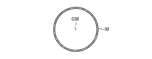
- FIG. 5 is a second view illustrating the tubular member 32, and is a cross-sectional view perpendicular to the axis C32 of the tubular member 32.
- one end 32a of the two ends 32a and 32b is in contact with one main surface 21 of the metal member 20, and the other end 32b is the other of the ceramic member 10. Is in contact with the main surface 12 of the.
- one end 32a and one main surface 21 of the metal member 20 are joined by a brazing material (not shown), and the other end 32b and the other main surface 12 of the ceramic member 10 are not shown. It is joined by a non-wax material.
- the cross section of the tubular member 32 perpendicular to the axis C32 direction is circular (see FIG. 5).
- the tubular member 32 arranged inside the through hole 31a regulates the movement of fluid between the inside of the through hole 31a and the inside of the metal layer 31.
- the tubular member 32 arranged inside the through hole 31c regulates the movement of the fluid between the inside of the through hole 31c and the inside of the metal layer 31.
- the through hole 25 of the metal member 20, the through hole 31c of the metal layer 31, and the helium gas flowing through the through hole 17 of the ceramic member 10 are suppressed from leaking into the inside of the metal layer 31, and the metal layer is prevented from leaking. Fragments of the metal fiber of 31 are suppressed from falling into the through hole 31c.
- the brazing filler metal 33 is a silver (Ag) -based brazing filler metal, and while entering the plurality of holes of the metal layer 31, the other main surface 12 of the ceramic member 10 and the one main surface 21 of the metal member 20 respectively. It is joined to.
- the brazing material 33 is a brazing material containing titanium (Ti), a filler material such as solder, an adhesive material such as a silicone resin, an acrylic resin, an epoxy resin, or an inorganic adhesive material such as glass paste. There may be.
- a metal foil hereinafter, “” “Metal leaf on the metal member side”
- the metal layer 31 on which the through holes 31a, 31b, and 31c are formed is arranged on the metal foil on the metal member side, and the tubular member 32 is inserted into each of the through holes 31a, 31c.
- another metal foil hereinafter referred to as "metal foil on the ceramic member side" to be the brazing material 33 is arranged on the side of the metal layer 31 opposite to the metal member 20.
- the ceramic member 10 is arranged on the metal foil on the ceramic member side, the ceramic member 10 and the metal layer 31 are joined by using the metal foil on the ceramic member side, and the metal member 20 and the metal member 20 are joined by using the metal foil on the metal member side. It is joined to the metal layer 31. As a result, the bonded body 1a is completed.
- the electrostatic chuck 1 is completed by assembling the electrode terminal 15 and the lift pin 18 to the completed joint body 1a.
- FIG. 6 is a cross-sectional view of the electrostatic chuck 5 of the comparative example.
- the tubular member 32 on the electrostatic chuck 1 of the present embodiment will be described in comparison with the electrostatic chuck 5 of the comparative example.
- the tubular member is not arranged inside the through holes 31a and 31c of the joint portion 30.
- the processing gas stays around the electrostatic chuck 5.
- This processing gas may flow into the through hole 31a through a plurality of holes formed inside the metal layer 31 (see the dotted arrow F01 in FIG. 6). Further, with the inflow of the processing gas at this time, fragments of the metal fibers of the metal layer 31 may fall into the through hole 31a.
- the through hole 25 of the metal member 20, the through hole 31c of the joint portion 30, and the ceramic member 10 are between the mounting surface 13 and the wafer W.
- Helium gas is supplied through the through hole 17 of the above.
- the helium gas passing through the inside of the through hole 31c of the joint portion 30 leaks from the through hole 31c to the plurality of holes of the metal layer 31 (see the dotted arrow F02 in FIG. 6).
- the flow rate of helium gas flowing through the through hole 31c may decrease, and it is difficult to stably supply helium gas between the mounting surface 13 and the wafer W.
- the residual gas in the joint portion 30 may flow into the through hole 31c, and the inflow of the residual gas into the through hole 31c may contaminate the wafer W. Further, with the inflow of the residual gas, the fragments of the metal fibers of the metal layer 31 fall into the through hole 31c and move to the mounting surface 13 together with the helium gas, and adhere to the wafer W to contaminate the wafer W. There is a risk.
- the tubular member 32 is arranged inside the through hole 31a of the joint portion 30 (see FIG. 3).
- the processing gas staying around the electrostatic chuck 1 is blocked by the tubular member 32 arranged inside the through hole 31a, so that it is difficult for the processing gas to flow into the through holes 23, 31a and the recess 14 (FIG. 3).
- the fragments of the metal fibers of the metal layer 31 are also suppressed from entering the through holes 23, 31a and the recess 14 by the tubular member 32.
- the tubular member 32 is arranged inside the through hole 31c of the joint portion 30 (see FIG. 3).
- the helium gas flowing through the through hole 31c of the joint portion 30 does not leak into the inside of the metal layer 31 in the through hole 31c, and is stably supplied between the mounting surface 13 and the wafer W ( (See the dotted arrow F12 in FIG. 3), the helium gas atmosphere between the mounting surface 13 and the wafer W can be stabilized.
- the residual gas in the joint portion 30 is suppressed from flowing into the through hole 31c, contamination of the wafer W is suppressed.
- the debris of the metal fiber of the metal layer 31 is suppressed from falling into the through hole 31c with the inflow of the residual gas of the joint portion 30, the debris is suppressed from contaminating the wafer W.
- the metal layer 31 included in the joint portion 30 has a plurality of holes communicating with each other, and the metal layer 31 is formed on the metal member 20.
- Through holes 31a and 31c communicating with the through holes 23 and 25 are formed.
- a tubular member 32 that regulates the movement of gas between the inside of each of the through holes 31a and 31c and the inside of the metal layer 31 is arranged inside each of the through holes 31a and 31c of the metal layer 31 arranged. ..
- the tubular member 32 arranged inside the through hole 31a suppresses the inflow of the processing gas of the wafer W into the through hole 31a, and the metal fiber fragments of the metal layer 31 fall into the through hole 31a. Can be suppressed.
- tubular member 32 arranged inside the through hole 31c is a through hole for the metal fiber fragments of the metal layer 31 while suppressing the leakage of helium gas flowing through the through hole 31c into the metal layer 31. It is possible to suppress the fall to 31a.
- the through holes 25 and 31c formed in the metal member 20 and the metal layer 31, respectively, and the through holes 17 formed in the ceramic member 10 communicate with each other.
- the through hole 31c formed in the metal layer 31 helium gas flowing through the through hole 31c is suppressed from leaking to the metal layer 31, and fluid inside the metal layer 31 is suppressed from flowing into the inside of the through hole 31c. Therefore, the change in the flow rate of the helium gas flowing through the through hole 17 of the ceramic member 10 with respect to the flow rate of the helium gas flowing through the through hole 25 of the metal member 20 becomes small.
- the helium gas can be stably supplied from the metal member 20 side to the ceramic member 10 side across the bonded body 1a, so that the helium gas can be stably supplied between the wafer W and the mounting surface 13. Can be supplied.
- the tubular member 32 is formed of the same material as the metal layer 31.
- the joint portion 30 is formed of two types of materials, the material of the metal layer 31 and the tubular member 32, and the material of the brazing material 33, so that the brazing material, the metal layer, and the tubular member are separate.
- the composition of the joint portion 30 becomes uniform regardless of the site. Therefore, the difference in thermal stress between the portions is less likely to occur in the joint portion 30, and damage to the joint body 1a can be suppressed.
- the tubular member 32 is formed so that the cross section perpendicular to the axis C32 direction has a circular shape. As a result, the tubular member 32 is less likely to be deformed by the force acting from the direction intersecting the axis C32, so that the fluid moves between the through holes 31a and 31c and the metal layer 31 and the through holes 31a and 31c It is possible to further suppress the falling of the debris of the metal layer 31 to the metal layer 31.
- FIG. 7 is a cross-sectional view of the electrostatic chuck 2 of the second embodiment.
- the electrostatic chuck 2 of the second embodiment has a different shape of the tubular member as compared with the electrostatic chuck 1 of the first embodiment (FIG. 3).
- the electrostatic chuck 2 of the present embodiment includes a ceramic member 10, an electrode terminal 15, a lift pin 18, a metal member 20, and a joint portion 40.
- the joint portion 40 joins the ceramic member 10 and the metal member 20, and includes a metal layer 31, a tubular member 42, and a brazing material 33.
- the joint body 2a composed of the ceramic member 10, the joint portion 40, and the metal member 20 is a substantially circular columnar body.
- the tubular member 42 is a member having a substantially cylindrical shape, and is a member that is open up and down and whose side surface is sealed. As shown in FIG. 7, the tubular member 42 is arranged inside each of the through hole 31a and the through hole 31c.
- the tubular member 42 arranged inside the through hole 31a suppresses the inflow of the processing gas of the wafer W into the through hole 31a and suppresses the falling of the metal fiber fragments of the metal layer 31 into the through hole 31a. do.
- the tubular member 42 arranged inside the through hole 31c suppresses the leakage of helium gas flowing through the through hole 31c into the metal layer 31, while suppressing the leakage of helium gas flowing through the through hole 31c into the through hole 31a of the metal fiber fragments of the metal layer 31. Suppress the fall to.
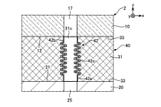
- FIG. 8 is an enlarged cross-sectional view of the electrostatic chuck 2 and is an enlarged view of part B in FIG.
- the tubular member 42 has two ends 42a, 42b and a bellows portion 42c connecting the two ends 42a, 42b.
- One end portion 42a is located on the minus side of the tubular member 42 in the z-axis direction and comes into contact with one main surface 21 of the metal member 20.
- the other end portion 42b is located on the positive side of the tubular member 42 in the z-axis direction and comes into contact with the other main surface 12 of the ceramic member 10.
- the bellows portion 42c is formed on the outer periphery of the tubular member 42 over the circumferential direction. The bellows portion 42c is deformed according to the relationship between the position of one end portion 42a and the position of the other end portion 42b.
- a bellows portion 42c is formed on the outer periphery of the tubular member 42 in the circumferential direction.
- FIG. 9 is a partial cross-sectional view of the electrostatic chuck 3 of the third embodiment.
- the electrostatic chuck 3 of the third embodiment is different from the electrostatic chuck 1 of the first embodiment (FIG. 3) in the position of the end portion of the tubular member.
- the electrostatic chuck 3 of the present embodiment includes a ceramic member 10, an electrode terminal 15, a lift pin 18, a metal member 20, and a joint portion 50.
- the joint portion 50 joins the ceramic member 10 and the metal member 20, and includes a metal layer 31, tubular members 52 and 53, and a brazing material 33.
- the joint body 3a composed of the ceramic member 10, the joint portion 50, and the metal member 20 is a substantially circular columnar body.
- the tubular member 52 is a cylindrical member, which is a member which is open vertically and whose side surface is sealed, and is arranged inside the through hole 31a of the metal layer 31. As shown in FIG. 9, the tubular member 52 has one end 52a of the two ends 52a and 52b arranged inside the through hole 23 of the metal member 20. The other end 52b is in contact with the other main surface 12 of the ceramic member 10. As a result, it becomes difficult to form a gap between the metal member 20 and the tubular member 52, so that the inflow of the processing gas of the wafer W into the through hole 31a is suppressed, and the metal fiber fragments of the metal layer 31 penetrate. The fall into the hole 31a is suppressed.
- the other end portion 52b of the tubular member 52 may be arranged in a groove formed in the other main surface 12 of the ceramic member 10.
- FIG. 10 is an enlarged cross-sectional view of the electrostatic chuck 3 and is an enlarged view of a portion C in FIG.
- the tubular member 53 is a cylindrical member, which is a member which is open vertically and whose side surfaces are sealed, and is arranged inside the through hole 31c of the metal layer 31.
- one end 53a of the two ends 53a and 53b is arranged inside the through hole 25 of the metal member 20.
- the other end 53b is arranged inside the through hole 17 of the ceramic member 10.
- one end 52a of the tubular member 52 is arranged inside the through hole 23 of the metal member 20.
- One end 53a of the tubular member 53 is arranged inside the through hole 25 of the metal member 20, and the other end 53b is arranged inside the through hole 17 of the ceramic member 10.
- the tubular members 52 and 53 are affected by the thermal stress generated inside the electrostatic chuck 3 when the ceramic member 10 and the metal member 20 are joined by the joint portion 50 or when the electrostatic chuck 3 is used at a high temperature. Separation from the ceramic member 10 and the metal member 20 is suppressed. Therefore, it is possible to further restrict the movement of the fluid between the inside of the through hole 31c and the inside of the metal layer 31, and further suppress the debris of the metal layer 31 from falling into the through hole 31c.
- the "joint” includes a ceramic member 10 and a metal member 20.
- the combination of members constituting the "joint body” is not limited to this.
- it may be a bonded body in which ceramic members are bonded to each other, or a bonded body in which metal members are bonded to each other.
- it may be formed of materials other than ceramics and metals.
- it may be formed of a resin such as glass, glass epoxy, a thermoplastic resin and a thermosetting resin, paper phenol, paper epoxy, a glass composite, a metal member having an insulating member thereof formed on the surface, or the like.
- the ceramic member 10 has a recess 14 communicating with the through hole 31a of the joint portion 30 and a through hole 17 as a "through hole of the second member" communicating with the through hole 31c.
- the "second member" may be formed with either a recess or a "through hole” that communicates with the through hole of the joint. Further, the recess and the through hole may not be formed, or a plurality of through holes may be formed.
- the tubular member is formed of a metal containing titanium, which is the same material as the metal layer.
- the material forming the tubular member and the material forming the metal layer may be different, and the material is not limited to the metal containing titanium.
- a metal other than titanium may be used, or a ceramic material such as alumina or aluminum nitride may be used.
- it is desirable that the tubular member is a dense body.
- the tubular member has a circular cross section perpendicular to the axial direction of the tubular member.
- the cross section of the tubular member perpendicular to the axial direction does not have to be circular.
- the electrostatic chuck is provided in the etching apparatus.
- the field of application of the electrostatic chuck is not limited to this.
- it may be an electrostatic chuck provided with a heater for heating the wafer.
- the electrostatic chuck includes a heater, the electrostatic chuck is used in a high temperature environment. Therefore, it is desirable that the material forming the tubular member is made of a metal having a high heat resistant temperature.
- the electrostatic chuck may be used for fixing, straightening, transporting, and the like of a wafer in a semiconductor manufacturing apparatus.
- the device including the "holding device” including the bonded body is not limited to the electrostatic chuck, and for example, a CVD (Chemical Vapor Deposition) device, a PVD (Physical Vapor Deposition) device, a PLD (Pulsed Laser Deposition) device, and the like. It may be used as a heater for a vacuum device, a susceptor, or a mounting table. Therefore, the force for holding the object to be held is not limited to the electrostatic attraction.
- CVD Chemical Vapor Deposition
- PVD Physical Vapor Deposition
- PLD Pulsed Laser Deposition
- At least one of the space between the ceramic member and the joint and the metal member and the joint may be provided with another layer such as a metal layer.
- the other layer may be, for example, a layer formed by evaporation of titanium in the brazing material forming the joint, a metallized layer formed in advance, or the like.
- the joints 1a, 2a, and 3a of the ceramic member 10, the joints 30, 40, and 50, and the metal member 20 are assumed to be substantially circular columnar bodies.
- the shape of the "joint” is not limited to this. For example, it may have a rectangular shape, a polygonal shape, or the like.
- one end 52a of the tubular member 52 arranged around the electrode terminal 15 is arranged inside the through hole 23 on one main surface 21 side of the metal member 20.
- the position where the end portion of the tubular member is arranged is not limited to this.
- FIG. 11 is a cross-sectional view of a modified example of the electrostatic chuck 3 of the third embodiment.
- one end 52a of the tubular member 52 is arranged inside the through hole 25 on the other main surface 22 side of the metal member 20. That is, the tubular member 52 may be arranged so as to penetrate the metal member 20. Further, in the third embodiment, the tubular member 53 may also be arranged so as to penetrate the ceramic member 10 and the metal member 20.
- one end 52a of the tubular member 52 is arranged inside the through hole 23 of the metal member 20, and the other end 52b is in contact with the other main surface 12 of the ceramic member 10. is doing.
- the tubular member of the joint portion may have any one of the two ends arranged inside the through hole of any one of the members adjacent to the joint portion. As a result, the tubular member is prevented from separating the end portion of the tubular member from the member inserted inside the through hole, so that between the inside of the through hole of the metal layer and the inside of the metal layer. While further restricting the movement of the fluid, it is possible to further prevent debris from the metal layer from falling into the through holes.
Landscapes
- Chemical & Material Sciences (AREA)
- Engineering & Computer Science (AREA)
- Ceramic Engineering (AREA)
- Materials Engineering (AREA)
- Structural Engineering (AREA)
- Organic Chemistry (AREA)
- Container, Conveyance, Adherence, Positioning, Of Wafer (AREA)
- Ceramic Products (AREA)
- Electrical Discharge Machining, Electrochemical Machining, And Combined Machining (AREA)
Priority Applications (4)
| Application Number | Priority Date | Filing Date | Title |
|---|---|---|---|
| JP2022543306A JP7300069B2 (ja) | 2020-08-21 | 2021-06-25 | 接合体、保持装置、および、静電チャック |
| CN202180013930.9A CN115066408B (zh) | 2020-08-21 | 2021-06-25 | 接合体、保持装置以及静电卡盘 |
| US18/041,284 US20230303457A1 (en) | 2020-08-21 | 2021-06-25 | Joined body, holding device, and electrostatic chuck |
| KR1020227027559A KR102814220B1 (ko) | 2020-08-21 | 2021-06-25 | 접합체, 유지 장치, 및 정전 척 |
Applications Claiming Priority (2)
| Application Number | Priority Date | Filing Date | Title |
|---|---|---|---|
| JP2020-139760 | 2020-08-21 | ||
| JP2020139760 | 2020-08-21 |
Publications (1)
| Publication Number | Publication Date |
|---|---|
| WO2022038898A1 true WO2022038898A1 (ja) | 2022-02-24 |
Family
ID=80350311
Family Applications (1)
| Application Number | Title | Priority Date | Filing Date |
|---|---|---|---|
| PCT/JP2021/024111 Ceased WO2022038898A1 (ja) | 2020-08-21 | 2021-06-25 | 接合体、保持装置、および、静電チャック |
Country Status (6)
| Country | Link |
|---|---|
| US (1) | US20230303457A1 (https=) |
| JP (1) | JP7300069B2 (https=) |
| KR (1) | KR102814220B1 (https=) |
| CN (1) | CN115066408B (https=) |
| TW (1) | TWI798730B (https=) |
| WO (1) | WO2022038898A1 (https=) |
Families Citing this family (2)
| Publication number | Priority date | Publication date | Assignee | Title |
|---|---|---|---|---|
| WO2021261284A1 (ja) * | 2020-06-26 | 2021-12-30 | 日本特殊陶業株式会社 | 接合体、および静電チャック |
| JPWO2025220065A1 (https=) * | 2024-04-15 | 2025-10-23 |
Citations (7)
| Publication number | Priority date | Publication date | Assignee | Title |
|---|---|---|---|---|
| JPS59156976A (ja) * | 1983-02-25 | 1984-09-06 | 臼井国際産業株式会社 | 金属部材とセラミツク部材との結合体及びその結合方法 |
| JP2004050267A (ja) * | 2002-07-23 | 2004-02-19 | Ngk Insulators Ltd | 接合体の製造方法および接合体 |
| JP2007331026A (ja) * | 2006-06-19 | 2007-12-27 | Nhk Spring Co Ltd | 接合体及び接合用ろう材 |
| JP2017033983A (ja) * | 2015-07-29 | 2017-02-09 | 京セラ株式会社 | 試料保持具 |
| JP2018006737A (ja) * | 2016-06-28 | 2018-01-11 | 日本特殊陶業株式会社 | 保持装置および保持装置の製造方法 |
| WO2018230446A1 (ja) * | 2017-06-13 | 2018-12-20 | 日本碍子株式会社 | 半導体製造装置用部材 |
| JP2020109806A (ja) * | 2019-01-07 | 2020-07-16 | 京セラ株式会社 | 試料保持具 |
Family Cites Families (6)
| Publication number | Priority date | Publication date | Assignee | Title |
|---|---|---|---|---|
| JP3485390B2 (ja) | 1995-07-28 | 2004-01-13 | 京セラ株式会社 | 静電チャック |
| US6490146B2 (en) * | 1999-05-07 | 2002-12-03 | Applied Materials Inc. | Electrostatic chuck bonded to base with a bond layer and method |
| DE60326599D1 (de) * | 2002-09-06 | 2009-04-23 | Ork Corp | Metallbalgrohr, verfahren zur herstellung desselben und flexibles rohr für hochdruckfluid |
| US8956459B2 (en) * | 2005-02-23 | 2015-02-17 | Kyocera Corporation | Joined assembly, wafer holding assembly, attaching structure thereof and method for processing wafer |
| US7709099B2 (en) * | 2005-07-04 | 2010-05-04 | Kyocera Corporation | Bonded body, wafer support member using the same, and wafer treatment method |
| US11715652B2 (en) * | 2018-09-28 | 2023-08-01 | Ngk Insulators, Ltd. | Member for semiconductor manufacturing apparatus |
-
2021
- 2021-06-25 KR KR1020227027559A patent/KR102814220B1/ko active Active
- 2021-06-25 WO PCT/JP2021/024111 patent/WO2022038898A1/ja not_active Ceased
- 2021-06-25 JP JP2022543306A patent/JP7300069B2/ja active Active
- 2021-06-25 TW TW110123298A patent/TWI798730B/zh active
- 2021-06-25 CN CN202180013930.9A patent/CN115066408B/zh active Active
- 2021-06-25 US US18/041,284 patent/US20230303457A1/en active Pending
Patent Citations (7)
| Publication number | Priority date | Publication date | Assignee | Title |
|---|---|---|---|---|
| JPS59156976A (ja) * | 1983-02-25 | 1984-09-06 | 臼井国際産業株式会社 | 金属部材とセラミツク部材との結合体及びその結合方法 |
| JP2004050267A (ja) * | 2002-07-23 | 2004-02-19 | Ngk Insulators Ltd | 接合体の製造方法および接合体 |
| JP2007331026A (ja) * | 2006-06-19 | 2007-12-27 | Nhk Spring Co Ltd | 接合体及び接合用ろう材 |
| JP2017033983A (ja) * | 2015-07-29 | 2017-02-09 | 京セラ株式会社 | 試料保持具 |
| JP2018006737A (ja) * | 2016-06-28 | 2018-01-11 | 日本特殊陶業株式会社 | 保持装置および保持装置の製造方法 |
| WO2018230446A1 (ja) * | 2017-06-13 | 2018-12-20 | 日本碍子株式会社 | 半導体製造装置用部材 |
| JP2020109806A (ja) * | 2019-01-07 | 2020-07-16 | 京セラ株式会社 | 試料保持具 |
Also Published As
| Publication number | Publication date |
|---|---|
| KR20220124252A (ko) | 2022-09-13 |
| KR102814220B1 (ko) | 2025-05-28 |
| CN115066408A (zh) | 2022-09-16 |
| TWI798730B (zh) | 2023-04-11 |
| JP7300069B2 (ja) | 2023-06-28 |
| US20230303457A1 (en) | 2023-09-28 |
| JPWO2022038898A1 (https=) | 2022-02-24 |
| CN115066408B (zh) | 2023-12-05 |
| TW202226438A (zh) | 2022-07-01 |
Similar Documents
| Publication | Publication Date | Title |
|---|---|---|
| JP7108586B2 (ja) | 保持装置 | |
| JP2017126641A (ja) | 保持装置 | |
| KR102929866B1 (ko) | 접합체 및 정전 척 | |
| JP7430489B2 (ja) | 静電チャック、静電チャック装置 | |
| WO2022038898A1 (ja) | 接合体、保持装置、および、静電チャック | |
| KR20130099792A (ko) | 이종접합 냉각구조체 및 그 제조방법 | |
| JP7828498B2 (ja) | 保持装置 | |
| JP7214868B2 (ja) | ウエハ載置台 | |
| JP2021111662A (ja) | 保持装置 | |
| JP7688551B2 (ja) | 保持部材及びその製造方法 | |
| JP7388998B2 (ja) | 保持装置 | |
| JP7710891B2 (ja) | 保持装置 | |
| KR102363647B1 (ko) | 베이스 플레이트 구조체 및 그 제조방법, 기판 고정 장치 | |
| JP7717026B2 (ja) | 保持装置及び静電チャック | |
| JP7674924B2 (ja) | 保持装置 | |
| JPH11323549A (ja) | 基板保持装置 | |
| JP7509731B2 (ja) | 保持装置 | |
| JP7774114B1 (ja) | 保持装置 | |
| JP3987841B2 (ja) | ウェハ保持装置 | |
| JP7721738B1 (ja) | 保持装置 | |
| JP7653927B2 (ja) | 保持装置 | |
| CN121549091A (zh) | 具备供电端子零件的构件 | |
| JP2025113271A (ja) | 保持装置 | |
| JP2019040998A (ja) | 試料保持具 | |
| JP2025159574A (ja) | 保持装置 |
Legal Events
| Date | Code | Title | Description |
|---|---|---|---|
| 121 | Ep: the epo has been informed by wipo that ep was designated in this application |
Ref document number: 21858048 Country of ref document: EP Kind code of ref document: A1 |
|
| ENP | Entry into the national phase |
Ref document number: 2022543306 Country of ref document: JP Kind code of ref document: A |
|
| ENP | Entry into the national phase |
Ref document number: 20227027559 Country of ref document: KR Kind code of ref document: A |
|
| NENP | Non-entry into the national phase |
Ref country code: DE |
|
| 122 | Ep: pct application non-entry in european phase |
Ref document number: 21858048 Country of ref document: EP Kind code of ref document: A1 |