WO2022034815A1 - Vehicle surroundings recognition device - Google Patents
Vehicle surroundings recognition device Download PDFInfo
- Publication number
- WO2022034815A1 WO2022034815A1 PCT/JP2021/028524 JP2021028524W WO2022034815A1 WO 2022034815 A1 WO2022034815 A1 WO 2022034815A1 JP 2021028524 W JP2021028524 W JP 2021028524W WO 2022034815 A1 WO2022034815 A1 WO 2022034815A1
- Authority
- WO
- WIPO (PCT)
- Prior art keywords
- time
- ego vehicle
- unit
- vehicle
- future
- Prior art date
- Legal status (The legal status is an assumption and is not a legal conclusion. Google has not performed a legal analysis and makes no representation as to the accuracy of the status listed.)
- Ceased
Links
Images


Classifications
-
- B—PERFORMING OPERATIONS; TRANSPORTING
- B60—VEHICLES IN GENERAL
- B60W—CONJOINT CONTROL OF VEHICLE SUB-UNITS OF DIFFERENT TYPE OR DIFFERENT FUNCTION; CONTROL SYSTEMS SPECIALLY ADAPTED FOR HYBRID VEHICLES; ROAD VEHICLE DRIVE CONTROL SYSTEMS FOR PURPOSES NOT RELATED TO THE CONTROL OF A PARTICULAR SUB-UNIT
- B60W40/00—Estimation or calculation of non-directly measurable driving parameters for road vehicle drive control systems not related to the control of a particular sub unit, e.g. by using mathematical models
- B60W40/02—Estimation or calculation of non-directly measurable driving parameters for road vehicle drive control systems not related to the control of a particular sub unit, e.g. by using mathematical models related to ambient conditions
-
- B—PERFORMING OPERATIONS; TRANSPORTING
- B60—VEHICLES IN GENERAL
- B60W—CONJOINT CONTROL OF VEHICLE SUB-UNITS OF DIFFERENT TYPE OR DIFFERENT FUNCTION; CONTROL SYSTEMS SPECIALLY ADAPTED FOR HYBRID VEHICLES; ROAD VEHICLE DRIVE CONTROL SYSTEMS FOR PURPOSES NOT RELATED TO THE CONTROL OF A PARTICULAR SUB-UNIT
- B60W50/00—Details of control systems for road vehicle drive control not related to the control of a particular sub-unit, e.g. process diagnostic or vehicle driver interfaces
- B60W50/08—Interaction between the driver and the control system
- B60W50/14—Means for informing the driver, warning the driver or prompting a driver intervention
-
- B—PERFORMING OPERATIONS; TRANSPORTING
- B60—VEHICLES IN GENERAL
- B60W—CONJOINT CONTROL OF VEHICLE SUB-UNITS OF DIFFERENT TYPE OR DIFFERENT FUNCTION; CONTROL SYSTEMS SPECIALLY ADAPTED FOR HYBRID VEHICLES; ROAD VEHICLE DRIVE CONTROL SYSTEMS FOR PURPOSES NOT RELATED TO THE CONTROL OF A PARTICULAR SUB-UNIT
- B60W60/00—Drive control systems specially adapted for autonomous road vehicles
- B60W60/001—Planning or execution of driving tasks
- B60W60/0011—Planning or execution of driving tasks involving control alternatives for a single driving scenario, e.g. planning several paths to avoid obstacles
-
- G—PHYSICS
- G08—SIGNALLING
- G08G—TRAFFIC CONTROL SYSTEMS
- G08G1/00—Traffic control systems for road vehicles
- G08G1/01—Detecting movement of traffic to be counted or controlled
- G08G1/0104—Measuring and analyzing of parameters relative to traffic conditions
- G08G1/0108—Measuring and analyzing of parameters relative to traffic conditions based on the source of data
- G08G1/0112—Measuring and analyzing of parameters relative to traffic conditions based on the source of data from the vehicle, e.g. floating car data [FCD]
-
- G—PHYSICS
- G08—SIGNALLING
- G08G—TRAFFIC CONTROL SYSTEMS
- G08G1/00—Traffic control systems for road vehicles
- G08G1/01—Detecting movement of traffic to be counted or controlled
- G08G1/0104—Measuring and analyzing of parameters relative to traffic conditions
- G08G1/0125—Traffic data processing
- G08G1/0133—Traffic data processing for classifying traffic situation
-
- G—PHYSICS
- G08—SIGNALLING
- G08G—TRAFFIC CONTROL SYSTEMS
- G08G1/00—Traffic control systems for road vehicles
- G08G1/01—Detecting movement of traffic to be counted or controlled
- G08G1/0104—Measuring and analyzing of parameters relative to traffic conditions
- G08G1/0137—Measuring and analyzing of parameters relative to traffic conditions for specific applications
- G08G1/0141—Measuring and analyzing of parameters relative to traffic conditions for specific applications for traffic information dissemination
-
- G—PHYSICS
- G08—SIGNALLING
- G08G—TRAFFIC CONTROL SYSTEMS
- G08G1/00—Traffic control systems for road vehicles
- G08G1/01—Detecting movement of traffic to be counted or controlled
- G08G1/04—Detecting movement of traffic to be counted or controlled using optical or ultrasonic detectors
-
- B—PERFORMING OPERATIONS; TRANSPORTING
- B60—VEHICLES IN GENERAL
- B60W—CONJOINT CONTROL OF VEHICLE SUB-UNITS OF DIFFERENT TYPE OR DIFFERENT FUNCTION; CONTROL SYSTEMS SPECIALLY ADAPTED FOR HYBRID VEHICLES; ROAD VEHICLE DRIVE CONTROL SYSTEMS FOR PURPOSES NOT RELATED TO THE CONTROL OF A PARTICULAR SUB-UNIT
- B60W50/00—Details of control systems for road vehicle drive control not related to the control of a particular sub-unit, e.g. process diagnostic or vehicle driver interfaces
- B60W50/08—Interaction between the driver and the control system
- B60W50/14—Means for informing the driver, warning the driver or prompting a driver intervention
- B60W2050/146—Display means
-
- B—PERFORMING OPERATIONS; TRANSPORTING
- B60—VEHICLES IN GENERAL
- B60W—CONJOINT CONTROL OF VEHICLE SUB-UNITS OF DIFFERENT TYPE OR DIFFERENT FUNCTION; CONTROL SYSTEMS SPECIALLY ADAPTED FOR HYBRID VEHICLES; ROAD VEHICLE DRIVE CONTROL SYSTEMS FOR PURPOSES NOT RELATED TO THE CONTROL OF A PARTICULAR SUB-UNIT
- B60W2420/00—Indexing codes relating to the type of sensors based on the principle of their operation
- B60W2420/40—Photo, light or radio wave sensitive means, e.g. infrared sensors
- B60W2420/403—Image sensing, e.g. optical camera
-
- B—PERFORMING OPERATIONS; TRANSPORTING
- B60—VEHICLES IN GENERAL
- B60W—CONJOINT CONTROL OF VEHICLE SUB-UNITS OF DIFFERENT TYPE OR DIFFERENT FUNCTION; CONTROL SYSTEMS SPECIALLY ADAPTED FOR HYBRID VEHICLES; ROAD VEHICLE DRIVE CONTROL SYSTEMS FOR PURPOSES NOT RELATED TO THE CONTROL OF A PARTICULAR SUB-UNIT
- B60W2554/00—Input parameters relating to objects
- B60W2554/40—Dynamic objects, e.g. animals, windblown objects
- B60W2554/404—Characteristics
- B60W2554/4041—Position
-
- B—PERFORMING OPERATIONS; TRANSPORTING
- B60—VEHICLES IN GENERAL
- B60W—CONJOINT CONTROL OF VEHICLE SUB-UNITS OF DIFFERENT TYPE OR DIFFERENT FUNCTION; CONTROL SYSTEMS SPECIALLY ADAPTED FOR HYBRID VEHICLES; ROAD VEHICLE DRIVE CONTROL SYSTEMS FOR PURPOSES NOT RELATED TO THE CONTROL OF A PARTICULAR SUB-UNIT
- B60W2554/00—Input parameters relating to objects
- B60W2554/40—Dynamic objects, e.g. animals, windblown objects
- B60W2554/404—Characteristics
- B60W2554/4042—Longitudinal speed
-
- B—PERFORMING OPERATIONS; TRANSPORTING
- B60—VEHICLES IN GENERAL
- B60W—CONJOINT CONTROL OF VEHICLE SUB-UNITS OF DIFFERENT TYPE OR DIFFERENT FUNCTION; CONTROL SYSTEMS SPECIALLY ADAPTED FOR HYBRID VEHICLES; ROAD VEHICLE DRIVE CONTROL SYSTEMS FOR PURPOSES NOT RELATED TO THE CONTROL OF A PARTICULAR SUB-UNIT
- B60W2554/00—Input parameters relating to objects
- B60W2554/80—Spatial relation or speed relative to objects
- B60W2554/802—Longitudinal distance
Definitions
- the present disclosure relates to a vehicle surroundings recognition device for an ego vehicle, in particular, which reduces complexity, e.g., of the hardware which is used and which provides increased accuracy and reliability of the output, and which is generally applicable because it can be integrated easily into vehicles or mono cameras.
- Autonomous vehicles rely on sensors to recognize the surrounding environment (surroundings) including objects therein.
- Typical autonomous vehicle software architectures fuse information from multiple sensors such as cameras, LiDARs and radars to accurately perceive the environment. Cameras are used to detect and classify object types such as vehicles, traffic signs, pedestrians, etc. LiDARs are used to measure the position and orientation of objects whilst radars are used to measure the velocity.
- US2019/0317519A1 describes a system architecture which uses a three-dimensional (3D) distance determination module which determines a distance to an object based on a 3D representation having a dimension that best matches the dimensions (e.g., a length, a width, or an area, e.g., length by width) of a two-dimensional (2D) bounding/boundary box.
- the module for the distance estimation is based on search algorithms, such as greedy search or binary search.
- the distance to the object at the present time can only be estimated after the orientation and the 3D size of the object was estimated.
- WO2019/177562A1 describes a system architecture which uses machine learning models for detecting an object in an image and for determining the distance to the detected object at the present time.
- the present disclosure proposes a technology that can be used to simultaneously estimate and predict the pose (i.e. position, orientation and its derivatives) and dimension of surrounding objects from a single optical sensor, e.g., a (mono) camera.
- a single optical sensor e.g., a (mono) camera.
- One benefit is the lower complexity and costs compared to existing approaches that require multiple sensors (e.g. camera, LiDAR, Radar) to achieve possibly the accuracy and reliability of the present disclosure.
- a vehicle surroundings recognition device for an ego vehicle which may include an optical sensor communicably connected to the vehicle surroundings recognition device.
- the optical sensor may be an imaging semiconductor, i.e. an image sensor, such as a CCD or CMOS sensor, or it may be a camera further including optical lenses and the like.
- the optical sensor is a single sensor or a mono camera. The use of a mono camera can save costs and reduces system complexity in comparison to, e.g., a stereo camera or a combination of different sensors, such as Lidar or radar.
- the vehicle surroundings recognition device may comprise at least or may be integrated into a computing unit and may be configured to receive image data at a present time t from the optical sensor mounted on the ego vehicle.
- the term “present time t” may preferably indicate the actual time while a time t-n belongs to the past and times t+k and t+Dt are future times.
- the image data may be received preferably at the present time t.
- the image data processing such as the object detection, may start at the present time t.
- the vehicle surroundings recognition device may further be configured to detect objects in the received image data, wherein an object may relate to persons, pedestrians, animals, vehicles, roadways, lane markers, hazards and objects in general relative to the position of the vehicle. It may further be configured to determine at least the distance between a (or each) detected object and the ego vehicle as well as the velocity of a (or each) detected object. The distance and the velocity is determined for the present time t, which preferably means at the time at which the image was taken/received/processing thereof started.
- the vehicle surroundings recognition device may be configured to predict at least a future distance of a (or each) detected object to the ego vehicle.
- a plurality of future distance values is determined for a (or each) detected object for a predefined time interval starting at the present time t to a future time t+k.
- a set of a future set/sequence of distance values for a detected object is generated, wherein the future time interval is segmented into a predefined number of time points for each of which a distance value is generated.
- a plurality of distance values at different times between the time t and the time t+k is determined.
- the vehicle surroundings recognition device may be configured to compensate the motion of the ego vehicle based on a processing and communication time delay Dt at the time t+Dt.
- the time interval Dt includes or is the time needed for the processing of the object detection and the prediction as well as for the signal transfer between subunits of the vehicle surroundings recognition device and/or within a network (latency).
- the time interval Dt may be measured in real-time by the vehicle surroundings recognition device, another vehicle control device or a dedicated sub unit, it may be estimated based on previous comparable scenarios or it may be calculated/determined if the relevant parameters are known or estimable.
- the compensation allows to recalculate, in particular, the position change of the ego vehicle during the short time interval from the time t to the time t+Dt.
- the vehicle surroundings recognition device may be configured to output a sequence of images including image frames in the interval of time t (preferably the interval starts at t+Dt) to t+k.
- the images may include the position of the ego vehicle and the (Cartesian) positions as well as (Euclidean) distances, dimensions, etc. of the detected object(s). The distances etc. may take into account the compensated/corrected position of the ego vehicle at the time t+Dt.
- the output may be fed to a route planning device of an autonomously driving ego vehicle, to a navigation system and/or to the driver of the ego vehicle.
- the present aspect allows technically beneficial that even only by use of a mono camera (a single optical sensor) a high accuracy and reliability of the output information about detected objects can be achieved.
- the information about the positions, and other information of the detect objects in the (near) future render possible a more precise route planning which, e.g., increases the safety in view of the avoiding of collisions.
- the accuracy is also increased due to the position correction of the ego vehicle’s position which changes during the time interval of receiving the image(s) from the optical sensor to the finalization of the processing of the image(s).
- the present device can take this shift of the position into account for further improved accuracy and reliability.
- the complexity of the system is reduced in comparison to ego vehicle systems which require a plurality of different input sources for detecting and recognizing the environment of the ego vehicle, e.g., the complexity of calibration between multiple sensors. Further, e.g., the integration into existing vehicle cameras, especially mono cameras, can be easily performed because of the technical benefit that a calibration of camera parameters or the like is not necessary.
- the vehicle surroundings recognition device may comprise a detection unit that at least may be communicably connected to the optical sensor of the ego vehicle and a prediction unit.
- the prediction unit preferably a part of the vehicle surroundings recognition device, may be at least communicably connected to the detection unit and an ego vehicle compensation unit, which may be a part of the vehicle surroundings recognition device.
- the ego vehicle compensation unit may be at least communicably connected to a processing and communication time delay determination unit, which may be part of another device, an ego vehicle driving parameters unit, which may be part of another device and which may receive data from sensors of the ego vehicle, such as speed sensors, yaw sensors, position sensors, engine parameter sensors, etc., the prediction unit and an output image data unit, which may be part of the vehicle surroundings recognition device.
- the detection unit may be configured to receive the image data from the optical sensor at the present time t, to detect one or more objects in the image data and to output object information data about the one or more detected objects to the prediction unit, said object information data of each of the one or more detected objects including at least the distance to the ego vehicle and the velocity at the present time t.
- the object information data may further include the object’s orientation, its bounding box coordinates, and its dimensions.
- the prediction unit may be configured to predict, at least based on said object information data received from the detection unit, future object information data about the one or more detected objects.
- Said future object information data of each of the one or more detected objects may include at least future distance values to the ego vehicle between the present time t and a future time t+k.
- the future object information data may further include the object’s orientation, its bounding box coordinates, and its dimensions.
- the ego vehicle compensation unit may be configured to correct the position of the ego vehicle at a time t+Dt based on ego vehicle driving data received from the ego vehicle driving parameters unit and the processing time delay Dt received from the processing time delay determination unit.
- the ego vehicle driving data may include the velocity, the yaw and the like of the ego vehicle.
- the processing time delay determination unit may be configured to measure, estimate, calculate and/or determine the time interval Dt (latency).
- the output image data unit may be configured to receive the corrected position of the ego vehicle at the time t+Dt, said object information data output by the detection unit and said future object information data output by the prediction unit and to generate a sequence of image data from time t+Dt to time t+k in a time interval from the time t to t+Dt.
- the time interval t to t+Dt is the time interval during which the processing/generation of the future image data/object information data is performed.
- the image data may at least include all detected objects including their (future) object information data as well as the position of the ego vehicle.
- the setup of the communicably interconnected units allows to process the received image data flexibly in different use scenarios.
- the object distance estimation may be separated from the object detection and thus two specialized and therefore more precise units configured/trained for a specific purpose can be employed.
- the units can be distributed over different locations in a system possibly including remote computing units, the computing unit in the ego vehicle and the like which allows to adapt the hardware architecture to different use scenarios.
- the image data received by the detection unit at the present time t may comprise/may be formatted as a sequence of image frames including a plurality of frames from a time t-n to the present time t, wherein t-n is a time in the past relative to the present time t.
- the number of frames may be defined by time (or time difference) or by a predefined value, e.g. it may be defined that a time frame is set for each millisecond or shorter or longer, or, e.g., it may be defined that in the time interval t-n to t a predefined number (irrespective of the duration of the interval) of frames shall be used/present.
- sequences of images/image frames as an input into the device provided at the time t improves the data base for the detection of objects and the prediction processing for calculating the images of the future time interval. Increased accuracy and reliability can be achieved thereby.
- the object detection which may be preferably a part of/integrated into the detection unit, may use a trained machine learning (ML) model and/or a trained artificial intelligence (AI) model for detecting an object.
- ML machine learning
- AI artificial intelligence
- the model(s) may be included in the detection unit or the detection unit may be communicably connected to the models if they are separately stored from the detection unit (e.g. in a network-based server/computing unit).
- the machine learning model and/or the artificial intelligence model of the detection unit may be trained to determine as the object information data, for each detected object, the type of the detected object, the orientation of the detected object in regard of an ego-vehicle-based coordinate system, a boundary box of the detected object and the coordinates in the ego vehicle based coordinate system, the dimensions (or size) of the detected object, the distance to the ego vehicle and/or the velocity of the detected object.
- the type of an object may be, as explained above, e.g. categorize the objects into pedestrian, car, truck, obstacle, or the like.
- the orientation of a detected object may be detected relative to the ego vehicle and may indicate, e.g. the direction of an axis thereof, e.g. the longitudinal axis.
- the term boundary box preferably may be a rectangular or 4-cornered area which is surrounding the outer dimensions of the detected object in the image plane (as close as possible without cutting the outer boundary lines of the object).
- the boundary box may be defined by the coordinates of its upper-left corner and bottom-right corner.
- the dimensions may include the length, the width, the height, etc. of the detected object and the size may indicate the area or one of the dimensions.
- the distance may be preferably defined based on a coordinate system which may have its origin at the optical sensor of the ego vehicle or any other well defined position of the ego vehicle.
- the above combination/set of parameters allows to detect and determine the position and the behavior of a detected object in a very precise manner while, at the same time, the number of parameters is relatively low which reduces computational effort and the data traffic.
- the entire device can achieve high accuracy/precision with a low complexity of the required hardware/software architecture.
- the prediction may use a trained machine learning model and/or a trained artificial intelligence model for performing, e.g., a time-series analysis for predicting the future information data.
- the model(s) may be included in the prediction unit or the prediction unit may be communicably connected to the models if they are separately stored from the prediction unit (e.g. in a network-based server).
- the machine learning model and/or the artificial intelligence model may be trained to determine as the future object information data, for each detected object and for a sequence of image frames in a time interval between the present time t or t+Dt and a future time t+k, the orientation of the detected object in regard of an ego vehicle based coordinate system, a boundary box of the detected object and the coordinates in the ego vehicle based coordinate system, the dimensions (or size) of the detected object, the distance to the ego vehicle and/or the velocity of the detected object.
- Providing the images for the predicted future behavior, position, and/or the like of each detected object enables superior precision and safety of the route planning or driving of the ego vehicle.
- the machine learning model and/or the artificial intelligence model may include a convolutional neural network for the detection and a recurrent neural network for the prediction.
- the detection of the distance of each detected object to the ego vehicle at a present time t may be performed by a separate step which preferably may mean that the detection unit and the prediction unit may be separated units/use different ML/AI models.
- the determination of the distance may be performed by a machine learning model and/or an artificial intelligence model trained for determining the distance from the input image data received from the optical sensor of the ego vehicle at the present time t, wherein the received input image data preferably may include a sequence of image frames with frames from a past time t-n to the present time t.
- the data related to the object detection and the prediction, and the compensated ego vehicle driving data may be merged in each image frame of a sequence of image frames in a time interval from the time t+Dt to the future time t+k.
- Each image in the time interval from the time t+Dt to the future time t+k may be transformed into an occupancy grid (OCG or ocg) of the surroundings/environment of the ego vehicle.
- the transformation may be performed by a dedicated ocg generator unit which may perform mathematical transformations for generating the ocgs based on the (future) object information data.
- the surroundings of the ego vehicle may preferably include the vicinity of the ego vehicle and very preferably, at least, the area which overlaps with the area captured by the optical sensor(s).
- a sequence of occupancy grid image frames in a time interval from the time t+Dt to the future time t+k may be output.
- future occupancy grids (a sequence of a plurality of occupancy grids images arranged in order of time) allows to intuitively grasp the future traffic development for the driver of the ego vehicle so that she/he can adapt the driving and it allows, if the ego vehicle drives autonomously, to precisely and reliably adapt the automatically determined driving course, e.g., if the ocgs are input into a route planning device/unit or a navigation device/unit of the ego vehicle. Further the evaluation of the output may also enable to infer control actions automatically, such as automated braking, acceleration, stirring, and the like.
- the compensation unit of the ego vehicle’s position may receive information about the processing delay time Dt caused by the detection and the prediction processing and the communication delay, and about the actual (linear) velocity and yaw rate of the ego vehicle at the time t; and may compute/determine a corrected position of the ego vehicle at a time t+Dt.
- the computing may be based on previously trained scenarios, such as applying an average value or the like, or it may use measured parameters such as computing power of the computing unit, transfer speed of the communication connections, and the like to calculate the correct value Dt in each case.
- the value Dt may be measured, e.g. by taking the time at which the image data was received from the optical sensor and by taking the time at which the processed data is available (at a previously defined point/step in the flow of the processing). In the previous example, the time difference would be the value Dt.
- the velocity and the yaw rate may be provided by sensors of the ego vehicle which may report to the ego vehicle driving information unit which may provide the data to the claimed device/the compensation determination step.
- the compensation determination is further increasing the precision of the data output because the positional error of the ego vehicle is excised which is caused by the time needed for processing the input data and the data transfer between different units.
- the compensation can be based on an estimation of vehicle’s motion using a physics based vehicle model. Knowing the initial Cartesian position of the vehicle, e.g. (X,Y), as well as the current velocity and the current yaw rate of the ego vehicle, the position (X,Y) at the next time step can be determined/estimated.
- the vehicle surroundings recognition device may include an ID tracker unit communicably connected to a memory unit which may store data of previously detected objects.
- the ID tracker unit may be configured to determine for each of the detected objects whether the object is a newly detected object or a previously detected object, and the object prediction may be configured to receive from the ID tracker unit information about the detected object being a newly detected object or a tracked previously detected object.
- the processing time can be reduced significantly because previously determined parameters/data can be read from the memory instead of re-determining them by the trained model or, at least, the training model has a well-defined starting point for the determination which reduces the computational effort.
- the vehicle surroundings recognition device may be (partially) a computer program product comprising computer-readable instructions executable in a computer system including one or more computers, wherein the units are hardware and/or software units.
- the computers may be arranged at the ego vehicle (installed in the ego vehicle) and/or located remotely to the ego vehicle, such as provided in network connected remote locations.
- the vehicle surroundings recognition device should be a computer program product, the above explained units may be software modules/units stored in a storage space accessible by the one or more computers.
- the vehicle surroundings recognition device may also be a combination of hardware and software and some units may be either software or hardware units.
- the units may be communicably connected via hardware and/or software signal communication channels and communicably connected via one or more networks, wherein the units are either arranged in a single hardware or are distributed over different hardware devices including computing units/hardware within the ego vehicle.
- the units discussed above may be part of a single unit or each unit may be a separate entity.
- the vehicle surroundings recognition device may even be part of a mono camera including the optical sensor and being installed in an ego vehicle where the camera/the vehicle surroundings recognition device is communicably connected with the control entity of the ego vehicle, such as its central control computer or the like.
- a preferable architecture may distribute the high-effort computing tasks, such as the detection of objects, the determination of parameters of a detected object and the prediction processing, to network-based (remote) computing resources while the ego vehicle based units may perform lower-effort computing tasks.
- This enables a quick and reliable processing of the input data. If however the reliability in view of avoiding mobile data transfer interruptions shall be increased, the above explained units may perform their processing completely/mostly in the computing unit within the ego vehicle, as far as technically possible.
- the network based resources may then provide support data, such as map data from a map server, position information, previously stored driving data or the like.
- the architecture can be flexibly adapted to the intended scenario providing another technical benefit.
- a computer program is disclosed which may be installed in one or more computing units, such as the computing unit(s) of the ego vehicle and/or remotely located computing units which are connected to the ego vehicle via a network.
- a system may include an optical sensor, such as a (mono) camera and the vehicle surroundings recognition device of at least one of the above aspects.
- the system may also include remote computing units, the ego vehicle with a control device, storage units, and one or more networks communicably interconnecting remotely arranged computing units and/or storage units and the ego vehicle.
- the herein disclosed device and system and computer program product enable to use a less complex architecture, especially in view of the sensor hardware of the ego vehicle, relying preferably only on a single sensor source for the input of data about the surroundings of the vehicle (except general information, such as map data or the like provided from computing units located in the network) while the output information is highly reliable and accurate and can even provide (near) future information about detected objects in the vehicle surroundings.
- the disclosed device, system and computer program product do not require knowledge of the camera’s intrinsic parameters (such as focal length, etc.) which renders the approach applicable to any (existing) monocular camera regardless of the interstices specification of the camera.
- the integration into existing vehicles or cameras is easily performable.
- FIG. 1 schematically shows an example of a system of the present disclosure.
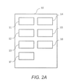
- FIG. 2A schematically shows an example configuration of a vehicle surroundings recognition device according to the present disclosure.
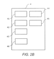
- FIG. 2B schematically shows an example configuration of a control device of an ego vehicle according to the present disclosure.
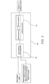
- FIG. 3 shows an example of a model training processing flow according to the present disclosure.
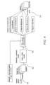
- FIG. 4 shows an example for a vehicle surroundings recognition processing flow according to the present disclosure.
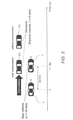
- FIG. 5 shows an example of the impact of the compensation processing of the present disclosure.
- FIG. 6 shows an example for a vehicle surroundings recognition processing flow according to the present disclosure.
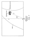
- FIG. 7 schematically shows the processing of an image taken by an optical sensor according to the present disclosure.
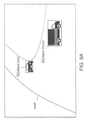
- FIG. 8A schematically shows the generation of an occupancy grid (OCG) or occupancy grid map according to the present disclosure.
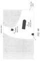
- FIG. 8B schematically shows the generation of an occupancy grid (OCG) or occupancy grid map according to the present disclosure.
- Figure 1 shows a schematic of a system 100 including an ego vehicle 1 with an optical sensor 2 (here shown as a preferably used mono camera) which is communicably connected (indicated by the bold broken arrows in the Figures) with a computing unit 3.
- the computing unit 3 is installed within the ego vehicle 1.
- the computing unit 3 as exemplarily shown by Figure 1 includes a vehicle surroundings recognition device 10 according to the present disclosure and a control entity/device 4 as well as a storage unit 5. If the vehicle surroundings recognition device 10 should be embodied as a software program product it may also be stored within the storage unit 5; which is not depicted in Figure 1. Alternatively, a computing unit may be an integral part of the control device 4 and/or the vehicle surroundings recognition device 10.
- the two devices/entities 4, 10 may also be integrated in a single control device or may be separated into more than one or two units.
- the communication links/lines/channels especially between the sub units within a device/unit are not depicted in the Figures for reasons of readability.
- the sub units within a higher order unit or device are interconnected to exchange information or signals with each other by way of software or hardware communication interfaces and/or lines.
- the computing unit 3 is communicably connected to one or more networks 6 indicated by the schematic cloud in Figure 1; further connected to the network 6 are remotely located storage unit(s) 7 and remotely located computing unit(s) 8a, 8b.
- the computing units 8a, 8b which are connected to the network 6 may include, e.g. a map server providing navigational data, such as map information to the ego vehicle 1, and further remote computing units 8a, 8b may include parts of the herein disclosed vehicle surroundings recognition device 10, especially preferable in case of computing-intense operations, such as the processing performed by AI/ML models.
- the number of remotely located computing units 8a, 8b may be lower or higher than the two shown in Figure 1.
- the remote storage space(s) 7 may store any kind of driving data or any other data which may support the operation of the herein described vehicle surroundings recognition device 10 or the operation of the computing unit 3 in the ego vehicle 1 or the like.
- Figures 2A and 2B show a schematic of the vehicle surroundings recognition device 10 and the control device 4.
- Figure 2A indicates that the vehicle surroundings recognition device 10 includes a plurality of subunits (even though a single subunit may be used as well; or more or less subunits than number of depicted subunits) including, as described further below, a detection unit 11, a prediction unit 12, an ego vehicle compensation unit 13 and an output unit 14 as well as an OCG generation unit 15.
- the vehicle surroundings recognition device 10 may also include a processing time delay determination unit 16 and an ID tracker unit 17 which may receive data from the vehicle-internal storage unit 5 or the remote storage unit 7.
- the vehicle surroundings recognition device 10 may have included its own computing unit (not depicted) and may have its own storage unit (not depicted) if the vehicle surroundings recognition device 10 is a separate hardware entity. The same holds for the control device 4. Further the control device 4 may also be merged with the vehicle surroundings recognition device 10 as described before.
- Figure 2B indicates that the control device 4 includes one or more subunits, such as an ego vehicle driving control unit 41, a sensor data processing unit 42, a brake control unit 43, an engine control unit 44 and the like. Furthermore, a travelling plan generation and travelling plan provision unit(s) 45 may be provided in the before described control device 4 or in a computing unit 8a, 8b located remotely to the ego vehicle 1.
- a travelling plan generation and travelling plan provision unit(s) 45 may be provided in the before described control device 4 or in a computing unit 8a, 8b located remotely to the ego vehicle 1.
- control device 4 may include an ego vehicle driving parameter unit 46 receiving data from sensors (not depicted) of the ego vehicle 1 or other not depicted sources, such as GPS signal data or the like.
- the vehicle driving control unit 41 may be configured, e.g., to perform an autonomous driving of the ego vehicle 1 and may receive input or provide control commands to other subunits, such as the sensor data processing unit 42 which may receive data from the ego vehicle driving parameter unit 46 and may provide driving-relevant data to the vehicle driving control unit 41. Further, the driving vehicle control unit 41 may control the brake control unit 43 and the engine control unit 44 which may control the brakes and engine(s), respectively, of the ego vehicle 1.
- a travelling plan generation/output unit 45 may be integrated into the ego vehicle 1 or it may be integrated into the remote computing unit(s) 8a, 8b and may support an autonomous driving by setting the route to be followed by the autonomously driven/controlled ego vehicle 1. The route may be provided to the vehicle driving control unit 41.
- the ego vehicle 1 or its computing unit 3 or its control device 4 may receive further information remotely via the network 6, such as map data from a map server, such as shown by reference sign 8a or 8b. It may also receive any kind of previously stored data from the remotely located
- the detection unit 11 as well as the prediction unit 12 may include one or more AI and/or ML models (not depicted) being trained in accordance with the schematic flow chart according to Figure 3.
- Figure 3 shows the principle flow of the training/learning process of the model(s) so that they can be used for a predefined purpose.
- Figure 3 shows a flow chart of the training steps and the depicted flow chart is shown in combination with the training unit 50 that performs the training steps: Firstly, raw image data (wherein raw shall mean that preferably it/they is/are not preprocessed) as well as measurements from sensors, such as Lidar sensors, radar sensors, optical sensors, GPS data, etc. are input into a data labelling and preparation process/unit 51. The data is labelled and prepared (processed, trimmed, etc.) so that it can be used for the training of, e.g., a neural network.
- raw image data wherein raw shall mean that preferably it/they is/are not preprocessed
- sensors such as Lidar sensors, radar sensors, optical sensors, GPS data, etc.
- the data is labelled and prepared (processed, trimmed, etc.) so that it can be used for the training of, e.g.,
- the labelling and preparing of the data may be performed in accordance with principles/process steps which are already known in the field. Then, the prepared data is input into the learning process/unit 52 as shown in Figure 3. Within the learning unit 52, the data is used for learning the model and afterwards the model is validated, as it is already known in the field. The model learning and the model validation are repeated as long as it is necessary for arriving at the necessary/desired precision of the trained model. This can be predetermined, e.g. by predetermining the number of iterations/repetitions. After the learning process, the model is sufficiently/well trained for being used as a detector model or a predictor model and is output from the training unit 50.
- Figure 4 further shows a principle flow of the processing which is carried out in the before described vehicle surroundings recognition device 10 according to Figure 2A and/or the system 100 shown in Figure 1.
- an optical sensor 2 which is preferably a mono camera for reducing the system complexity, takes images within a time period/interval of t-n to t wherein t is the present time.
- the optical sensor 2 provides (step S1) the images as a sequence of image frames wherein a plurality of image frames is inputted as a sequence.
- the sequence may be considered as a package/assembly of time-wise ordered images (schematically indicated in Figure 4).
- Said sequence is input into the detection and prediction unit(s) 11, 12 (step S2).
- the detection unit 11 uses the sequence of image frames provided by the optical sensor 2 to detect objects of interest for the ego vehicle driving.
- the objects O1, O2 may include pedestrians, other cars or trucks, obstacles, road markings, road boundaries, buildings and the like and in accordance with the training of the detection model, the detection unit 11 or a specific object information data model (which may be included in the detection unit 11 or in a separate sub unit not depicted in Figure 2A) determines the following object information data.
- the object information data detected/determined by the detection unit 11 may include object bounding/boundary box coordinates.
- the boundary box B may be considered as a rectangular area/box being arranged around the detected object O1, O2 so that the detected object O1, O2 precisely fits into the box B which is preferably a two-dimensional box placed in the image frame.
- the boundary box coordinates may be the upper left and the bottom right corner coordinates, fully defining the rectangular shape of the box B.
- the object information data may include the type of the object, preferably the orientation of the object with respect to the optical sensor coordinate system of the ego vehicle 1, a distance from the object to the optical sensor or the origin of the coordinate system of the ego vehicle, the dimension or size of the detected object and its velocity.
- an ID tracker unit 17 may also be included in the vehicle surroundings recognition device 10 to which the information about the detected object O1, O2 may be sent in order to receive information as to whether the detected object O1, O2 was already previously detected or whether it is newly detected. This will be described in further detail below.
- the predictor model 12 also uses a trained neural network model (not depicted) and applies a time series analysis on the information of each detected object O1, O2 in order to derive/infer future object information data.
- the future object information data may include the boundary box coordinates, orientation(s), distance, dimension(s) and/or velocity of each detected object in a future time interval being spanned from a present time t (or t+Dt) to a future time t+k.
- the number of values for each of the future object information data may be predefined, e.g. stored in the storage unit 7, or may be defined in accordance with the number of shorter time intervals between time t+Dt to time t+k.
- the ego vehicle compensation unit 13 receives data (step S3) from the driving data information unit 46 as well as a processing delay determination unit 16 in order to correct the position of the ego vehicle 1 in respect of the time that has passed (latency) in between of the present time t at which the last image of the time interval between t-n to t was taken (or the processing started) and the finishing of the detection and prediction processing as well as the related communication delays.
- the processing delay time determination unit 16 may measure this time being referred to as “Dt”, it may estimate the time based on previous cases or it may calculate the time if respective parameter data is available.
- the ego vehicle driving information unit 46 furthermore provides the actual linear velocity and the yaw of the ego vehicle 1 at the time t based on which, by extrapolation, for example, the new position of the ego vehicle 1 at the time t+Dt can be compensated/corrected/determined.
- the compensation also has an effect on the distances which are detected by the detector and the predictor units 11, 12 during their respective processing. Hence, the values are compensated as well, preferably.
- the distances between the ego vehicle 1 and any detected object O1, O2 may be determined by a separate trained AI/ML model, i.e. separate from the detector or predictor models.
- the separate model(s) may be sub units of the detector/predictor models; the models may be part of the device 10 as shown by Figure 2A.
- the distance determination may be performed by the trained model based on the input of the image data provided by the optical sensor 2.
- step S4 After the ego vehicle compensation was carried out and with the data from the detection unit and the prediction unit 11, 12 images provided in a sequence of image frames between time t (or time t+tD) and t+k can be generated by the output unit 14 or the OCG generation unit 15 (step S4), wherein the output unit 14 and the OCG generation unit 15 may be a single unit (different to the setup depicted in Figure 2A).
- the generation of the output preferably a sequence of occupancy grids in the time interval between the time t+Dt and t+k, will be explained in connection with Figures 7 and 8 below.
- Figure 5 shows the relative distance/position of a detected object O1, O2 and the ego vehicle 1 depending on the point of time which is the present time t at the time the images were taken by the optical sensor 2 and the time t+Dt after which the processing of the object detection and prediction was finalized.
- Figure 5 shows the example case in which the ego vehicle has a linear velocity of 10 m/s and a parked car O1 (velocity is 0 m/s) is detected.
- the processing of the object detection etc. takes the time Dt (shown as ⁇ t in the Figure 5) the ego vehicle 1 has travelled the distance ⁇ d from the original position at the time t.
- the compensation takes this into account and Figure 5 shows the differences in regard of the relative distances/positions of the detected object O1 and the ego vehicle 1.
- FIG. 6 an example flow of data/communication pattern between the different units is shown by Figure 6 which starts at the optical sensor 2 providing images to the object detector model in the detection unit 11 and to a latency estimator included in the processing time delay determination unit 16.
- the detector model detects objects O1, O2 in the images and provides information about the detected objects to an ID tracker unit 17, which furthermore receives information about previously tracked objects from a memory unit (e.g. the unit 7 or 5).
- the ID tracker unit 17 determines whether the detected object O1, O2 was previously detected and its information were stored in the memory. If so, the ID tracker may pass the information about the detected objects O1, O2 and whether they were newly detected or not to the object predictor model in the prediction unit 12.
- the prediction unit 12 may pass information to the latency estimator and to the ego vehicle compensation.
- the latency estimator may, e.g., receive the time t at which the images were put into the object detector model and the time at which the object predictor model output the predicted/future information. The time difference may be used for the calculation/estimation of the latency/time delay input into the ego vehicle compensation.
- the processing delay determination unit 16 receives information from the current images at the time t and the prediction model, and provides an estimate about the delay time/latency to the ego vehicle compensation unit 13 which furthermore receives at least information about the linear velocity and the yaw rate of the ego vehicle 1 at the present time t.
- the output of the ego vehicle compensation unit 13 and the object prediction model unit 12 then includes future object information data in a time interval between time t+Dt and the future time t+k. Based on this, as described above, a sequence of image frames in the future time interval between t (t+Dt) and t+k can be generated, which are preferably occupancy grid maps as further explained below.
- Figures 7, 8A and 8B An example for the occupancy generation is shown by Figures 7, 8A and 8B.
- Figure 7 shows a possible image taken by the optical sensor 2 of the ego vehicle 1.
- the image shows a road, the not further specified surroundings of the road (also labelled as “unknown area” in Figure 8B) and another vehicle (object O1).
- object O1 another vehicle
- a boundary box B is placed around the object O1, which was detected by the object detection and it was identified as “car”.
- a center of the image (image frame) P1 and a center of the boundary box B are shown as well as a virtual line crossing “P1” and a virtual line connection “P1” and “P2”, the first being indicated as L1 and the second being indicated as L2 in Figure 7.
- the (polar) angle in between the two lines L1, L2 is detected. The angle is identified as “theta” in Figure 7.
- the polar angle shown as “theta” in Figure 7 can be computed and based on which the location of the detected object O1, O2 in a Cartesian coordinate system can be computed. More specifically, the polar angle “theta” and the distance from the object O1 to the ego vehicle can be used to compute the location of the object O1 in Cartesian coordinates.
- an occupancy grid (OCG) can be generated.
- OCG occupancy grid
- an occupied area of an OCG is computed based on the (future) object information data, especially the orientation, dimension, distance to the ego vehicle 1 and the boundary box B.
- the detected object Using the detected object’s location, its orientation and dimension, the occupied area of this object O1, O2 in the occupancy grid map can be provided.
- Figures 8A and 8B an example is shown for converting an image with the detected objects O1, O2 ( Figure 8A) into an occupancy grid ( Figure 8B).
- FIG 8A one can see that a truck and a car have been detected as objects O1 and O2 travelling on the detected road.
- the detection model has put boundary boxes B around the two objects O1, O2 and based on the further (future) object information data discussed above, a transformation of the image shown in Figure 8A can be performed so that an occupancy grid map as shown in Figure 8B can be generated.
- Each of the occupancy grids from the time frame tD+t to the time frame t+k will display areas which are occupied by detected objects O1, O2, preferably in a bird’s eye view, as well as the road (marked as “free (i.e. unblocked) road space”), the surroundings of the road (here marked as “unknown area”), and optionally a part of the ego vehicle.
- the OCG sequence for the time interval between time t (t+Dt) and time t+k can be output to a display in the ego vehicle 1 so that the driver of the ego vehicle 1 can use the information for adapting the driving route or the like. Additionally or alternatively, the output can be provided to a control entity of the (semi-)autonomous ego vehicle 1 so that the control entity can control the driving route of the ego vehicle 1 automatically based on the information from the OCG sequence(s).
- a vehicle surroundings recognition device 10 and a system 100 as well as a related computer program product are described which offer increased reliability and safety because, inter alia, object information in the future can be predicted. This information can be used for avoiding collisions during the navigation with the ego vehicle 1 or if the ego vehicle 1 is an autonomous vehicle. Further, the accuracy of the output data can be improved, inter alia, due to the ego vehicle position compensation.
- a detailed occupancy grid map can be provided with more object information outputted from the model and a sequence of occupancy grid maps can be generated with the occupied areas of the detected objects being represented statically or dynamically.
- the system may use a mono camera or the like only instead of multiple sensor sources, as described in the prior art.
- Figures 1 and 2 show one possible example of the architecture of the herein described device 10 and system 100; and, for example, the distribution of sub units/units can be different.
- some of the subunits of the vehicle surroundings recognition device 10 may be located at one of or both of the remote computing units 8a, 8b or the entire vehicle surroundings recognition device 10 may be located in the remote computing unit(s) 8a, 8b while the data, especially the output data, is provided to the control device 3 of the ego vehicle 1 directly for the further processing and/or to a display of the ego vehicle 1.
- the present disclosure may be embodied as a method (e.g., a computer-implemented process or any other process), apparatus (including a device, machine, system, computer program product, and/or any other apparatus), or a combination of the foregoing.
- a method e.g., a computer-implemented process or any other process
- apparatus including a device, machine, system, computer program product, and/or any other apparatus
- aspects/Examples of the present disclosure may be a software entirely (including firmware, resident software, micro-code, etc.), or a combination of software and hardware aspects that may be referred to as a "system".
- the present disclosure may take the form of a computer program product on a computer-readable medium having computer-executable program code embodied in the medium.
- arrows may be used in drawings to represent communication, transfer, or other activity involving two or more entities. Double-ended arrows generally indicate that activity may occur in both directions (e.g., a command/request in one direction with a corresponding reply back in the other direction, or peer-to-peer communications initiated by either entity), although in some situations, activity may not necessarily occur in both directions.
- Single-ended arrows generally indicate activity exclusively or predominantly in one direction, although it should be noted that, in certain situations, such directional activity actually may involve activities in both directions (e.g., a message from a sender to a receiver and an acknowledgement back from the receiver to the sender, or establishment of a connection prior to a transfer and termination of the connection following the transfer).
- activities in both directions e.g., a message from a sender to a receiver and an acknowledgement back from the receiver to the sender, or establishment of a connection prior to a transfer and termination of the connection following the transfer.
- the type of arrow used in a particular drawing to represent a particular activity is exemplary and should not be seen as limiting.
- the computer-executable program code may be provided to a processor of a general purpose computer, special purpose computer, or other programmable data processing apparatus to produce a particular machine, such that the program code, which executes via the processor of the computer or other programmable data processing apparatus, create means for implementing the functions/acts/outputs specified in the flowchart, block diagram block or blocks, figures, and/or written description.
- the computer-executable program code may also be stored in a computer-readable memory that can direct a computer or other programmable data processing apparatus to function in a particular manner, such that the program code stored in the computer readable memory produce an article of manufacture including instruction means which implement the function/act/output specified in the flowchart, block diagram block(s), figures, and/or written description.
- the computer-executable program code may also be loaded onto a computer or other programmable data processing apparatus to cause a series of operational steps to be performed on the computer or other programmable apparatus to produce a computer-implemented process such that the program code which executes on the computer or other programmable apparatus provides steps for implementing the functions/acts/outputs specified in the flowchart, block diagram block(s), figures, and/or written description.
- computer program implemented steps or acts may be combined with operator or human implemented steps or acts in order to carry out an embodiment of the disclosure.
- a device may include, without limitation, a bridge, router, bridge-router (brouter), switch, node, server, computer, appliance, or other type of device.
- Such devices typically include one or more network interfaces for communicating over a communication network and a processor (e.g., a microprocessor with memory and other peripherals and/or application-specific hardware) configured accordingly to perform device functions.
- Communication networks generally may include public and/or private networks; may include local-area, wide-area, metropolitan-area, storage, and/or other types of networks; and may employ communication technologies including, but in no way limited to, analog technologies, digital technologies, optical technologies, wireless technologies (e.g., Bluetooth), networking technologies, and internetworking technologies.
- communication technologies including, but in no way limited to, analog technologies, digital technologies, optical technologies, wireless technologies (e.g., Bluetooth), networking technologies, and internetworking technologies.
- devices may use communication protocols and messages (e.g., messages created, transmitted, received, stored, and/or processed by the device), and such messages may be conveyed by a communication network or medium.
- communication protocols and messages e.g., messages created, transmitted, received, stored, and/or processed by the device
- a communication message generally may include, without limitation, a frame, packet, datagram, user datagram, cell, or other type of communication message.
- references to specific communication protocols are exemplary, and it should be understood that alternatives may, as appropriate, employ variations of such communication protocols (e.g., modifications or extensions of the protocol that may be made from time-to-time) or other protocols either known or developed in the future.
- logic flows may be described herein to demonstrate various aspects of the disclosure, and should not be construed to limit the present disclosure to any particular logic flow or logic implementation.
- the described logic may be partitioned into different logic blocks (e.g., programs, modules, functions, or subroutines) without changing the overall results or otherwise departing from the true scope of the disclosure.
- logic elements may be added, modified, omitted, performed in a different order, or implemented using different logic constructs (e.g., logic gates, looping primitives, conditional logic, and other logic constructs) without changing the overall results or otherwise departing from the scope of the disclosure.
- logic constructs e.g., logic gates, looping primitives, conditional logic, and other logic constructs
- the present disclosure may be embodied in many different forms, including, but in no way limited to, a graphical processing unit as well as computer program logic for use with a processor (e.g., a microprocessor, microcontroller, digital signal processor, or general purpose computer), programmable logic for use with a programmable logic device (e.g., a Field Programmable Gate Array (FPGA) or other PLD), discrete components, integrated circuitry (e.g., an Application Specific Integrated Circuit (ASIC)), or any other means including any combination thereof
- Computer program logic implementing some or all of the described functionality is typically implemented as a set of computer program instructions that is converted into a computer executable form, stored as such in a computer readable medium, and executed by a microprocessor under the control of an operating system.
- Hardware-based logic implementing some or all of the described functionality may be implemented using one or more appropriately configured FPGAs.
- Computer program logic implementing all or part of the functionality previously described herein may be embodied in various forms, including, but in no way limited to, a source code form, a computer executable form, and various intermediate forms (e.g., forms generated by an assembler, compiler, linker, or locator).
- Source code may include a series of computer program instructions implemented in any of various programming languages (e.g., an object code, an assembly language, or a high-level language such as Fortran, python, C, C++, JAVA, JavaScript or HTML) for use with various operating systems or operating environments.
- the source code may define and use various data structures and communication messages.
- the source code may be in a computer executable form (e.g., via an interpreter), or the source code maybe converted (e.g., via a translator, assembler, or compiler) into a computer executable form.
- Computer-executable program code for carrying out operations of embodiments of the present disclosure may be written in an object oriented, scripted or unscripted programming language such as Java, Perl, Smalltalk, C++, or the like.
- the computer program code for carrying out operations of aspects of the present disclosure may also be written in conventional procedural programming languages, such as the "C" programming language or similar programming languages.
- Computer program logic implementing all or part of the functionality previously described herein may be executed at different times on a single processor (e.g., concurrently) or may be executed at the same or different times on multiple processors and may run under a single operating system process/thread or under different operating system processes/threads.
- computer process refers generally to the execution of a set of computer program instructions regardless of whether different computer processes are executed on the same or different processors and regardless of whether different computer processes run under the same operating system process/thread or different operating system processes/threads.
- the computer program may be fixed in any form (e.g., source code form, computer executable form, or an intermediate form) either permanently or transitorily in a tangible storage medium, such as a semiconductor memory device (e.g., a RAM, ROM, PROM, EEPROM, or Flash-Programmable RAM), a magnetic memory device (e.g., a diskette or fixed disk), an optical memory device (e.g., a CD-ROM), a PC card (e.g., PCMCIA card), or other memory device.
- a semiconductor memory device e.g., a RAM, ROM, PROM, EEPROM, or Flash-Programmable RAM
- a magnetic memory device e.g., a diskette or fixed disk
- an optical memory device e.g., a CD-ROM
- PC card e.g., PCMCIA card
- the computer program may be fixed in any form in a signal that is transmittable to a computer using any of various communication technologies, including, but in no way limited to, analog technologies, digital technologies, optical technologies, wireless technologies (e.g., Bluetooth), networking technologies, and internetworking technologies.
- various communication technologies including, but in no way limited to, analog technologies, digital technologies, optical technologies, wireless technologies (e.g., Bluetooth), networking technologies, and internetworking technologies.
- the computer program may be distributed in any form as a removable storage medium with accompanying printed or electronic documentation (e.g., shrink wrapped software), preloaded with a computer system (e.g., on system ROM or fixed disk), or distributed from a server or electronic bulletin board over the communication system (e.g., the Internet or World Wide Web).
- a computer system e.g., on system ROM or fixed disk
- a server or electronic bulletin board over the communication system (e.g., the Internet or World Wide Web).
- Hardware logic including programmable logic for use with a programmable logic device
- implementing all or part of the functionality previously described herein may be designed using traditional manual methods, or may be designed, captured, simulated, or documented electronically using various tools, such as Computer Aided Design (CAD), a hardware description language (e.g., VHDL or AHDL), or a PLD programming language (e.g., PALASM, ABEL, or CUPL).
- CAD Computer Aided Design
- a hardware description language e.g., VHDL or AHDL
- PLD programming language e.g., PALASM, ABEL, or CUPL
- the computer readable medium may be, for example but not limited to, an electronic, magnetic, optical, electromagnetic, infrared, or semiconductor system, apparatus, device, or medium.
- the computer readable medium include, but are not limited to, an electrical connection having one or more wires or other tangible storage medium such as a portable computer diskette, a hard disk, a random access memory (RAM), a read-only memory (ROM), an erasable programmable read-only memory (EPROM or Flash memory), a compact disc read-only memory (CD-ROM), or other optical or magnetic storage device.
- a portable computer diskette a hard disk
- RAM random access memory
- ROM read-only memory
- EPROM or Flash memory erasable programmable read-only memory
- CD-ROM compact disc read-only memory
- Programmable logic may be fixed either permanently or transitorily in a tangible storage medium, such as a semiconductor memory device (e.g., a RAM, ROM, PROM, EEPROM, or Flash-Programmable RAM), a magnetic memory device (e.g., a diskette or fixed disk), an optical memory device (e.g., a CD-ROM), or other memory device.
- a semiconductor memory device e.g., a RAM, ROM, PROM, EEPROM, or Flash-Programmable RAM
- a magnetic memory device e.g., a diskette or fixed disk
- an optical memory device e.g., a CD-ROM
- the programmable logic may be fixed in a signal that is transmittable to a computer using any of various communication technologies, including, but in no way limited to, analog technologies, digital technologies, optical technologies, wireless technologies (e.g., Bluetooth), networking technologies, and internetworking technologies.
- various communication technologies including, but in no way limited to, analog technologies, digital technologies, optical technologies, wireless technologies (e.g., Bluetooth), networking technologies, and internetworking technologies.
- the programmable logic may be distributed as a removable storage medium with accompanying printed or electronic documentation (e.g., shrink wrapped software), preloaded with a computer system (e.g., on system ROM or fixed disk), or distributed from a server or electronic bulletin board over the communication system (e.g., the Internet or World Wide Web).
- a computer system e.g., on system ROM or fixed disk
- a server or electronic bulletin board over the communication system
- some embodiments of the disclosure may be implemented as a combination of both software (e.g., a computer program product) and hardware. Still other aspects of the present disclosure are implemented as entirely hardware, or entirely software.
Landscapes
- Engineering & Computer Science (AREA)
- Physics & Mathematics (AREA)
- General Physics & Mathematics (AREA)
- Automation & Control Theory (AREA)
- Chemical & Material Sciences (AREA)
- Analytical Chemistry (AREA)
- Transportation (AREA)
- Mechanical Engineering (AREA)
- Human Computer Interaction (AREA)
- Mathematical Physics (AREA)
- Traffic Control Systems (AREA)
Abstract
A vehicle surroundings recognition device for an ego vehicle 1 that includes an optical sensor 2 which is communicably connected to the vehicle surroundings recognition device 10, wherein the vehicle surroundings recognition device 10 is configured to output a sequence of image data including at least the future distance between the ego vehicle 1 and the one or more detected objects O1, O2.
Description
The present disclosure relates to a vehicle surroundings recognition device for an ego vehicle, in particular, which reduces complexity, e.g., of the hardware which is used and which provides increased accuracy and reliability of the output, and which is generally applicable because it can be integrated easily into vehicles or mono cameras.
Autonomous vehicles rely on sensors to recognize the surrounding environment (surroundings) including objects therein. Typical autonomous vehicle software architectures fuse information from multiple sensors such as cameras, LiDARs and radars to accurately perceive the environment. Cameras are used to detect and classify object types such as vehicles, traffic signs, pedestrians, etc. LiDARs are used to measure the position and orientation of objects whilst radars are used to measure the velocity.
It is however a disadvantage that the vehicle requires the input of a plurality of different sensors, as described above, which increases the complexity of the hardware architecture as well as the software-based information processing.
Further, US2019/0317519A1 describes a system architecture which uses a three-dimensional (3D) distance determination module which determines a distance to an object based on a 3D representation having a dimension that best matches the dimensions (e.g., a length, a width, or an area, e.g., length by width) of a two-dimensional (2D) bounding/boundary box. The module for the distance estimation is based on search algorithms, such as greedy search or binary search. The distance to the object at the present time can only be estimated after the orientation and the 3D size of the object was estimated.
WO2019/177562A1 describes a system architecture which uses machine learning models for detecting an object in an image and for determining the distance to the detected object at the present time.
However, enabling further increased reliability and accuracy of the object detection and the information provided by a vehicle surroundings recognition device is still necessary, especially when less complex hardware systems are used, e.g. systems relying on the input of a mono camera (only) instead of a plurality of vehicle sensors.
It is an object of the herein described disclosure to provide a solution which, in particular, improves the accuracy and reliability of the output of a vehicle surroundings recognition device usable in vehicles, preferably autonomous vehicles, and which enables the use of a less expensive and a less complex hardware architecture which can be easily integrated.
In particular, the present disclosure proposes a technology that can be used to simultaneously estimate and predict the pose (i.e. position, orientation and its derivatives) and dimension of surrounding objects from a single optical sensor, e.g., a (mono) camera. One benefit is the lower complexity and costs compared to existing approaches that require multiple sensors (e.g. camera, LiDAR, Radar) to achieve possibly the accuracy and reliability of the present disclosure.
The following aspects are in particular provided.
A vehicle surroundings recognition device for an ego vehicle which may include an optical sensor communicably connected to the vehicle surroundings recognition device. The optical sensor may be an imaging semiconductor, i.e. an image sensor, such as a CCD or CMOS sensor, or it may be a camera further including optical lenses and the like. Most preferably, the optical sensor is a single sensor or a mono camera. The use of a mono camera can save costs and reduces system complexity in comparison to, e.g., a stereo camera or a combination of different sensors, such as Lidar or radar.
The vehicle surroundings recognition device may comprise at least or may be integrated into a computing unit and may be configured to receive image data at a present time t from the optical sensor mounted on the ego vehicle. The term “present time t” may preferably indicate the actual time while a time t-n belongs to the past and times t+k and t+Dt are future times. The image data may be received preferably at the present time t. Preferably the image data processing, such as the object detection, may start at the present time t.
The vehicle surroundings recognition device may further be configured to detect objects in the received image data, wherein an object may relate to persons, pedestrians, animals, vehicles, roadways, lane markers, hazards and objects in general relative to the position of the vehicle. It may further be configured to determine at least the distance between a (or each) detected object and the ego vehicle as well as the velocity of a (or each) detected object. The distance and the velocity is determined for the present time t, which preferably means at the time at which the image was taken/received/processing thereof started.
Further the vehicle surroundings recognition device may be configured to predict at least a future distance of a (or each) detected object to the ego vehicle. Preferably, a plurality of future distance values is determined for a (or each) detected object for a predefined time interval starting at the present time t to a future time t+k. More preferably, a set of a future set/sequence of distance values for a detected object is generated, wherein the future time interval is segmented into a predefined number of time points for each of which a distance value is generated. In other words, preferably, for each detected object a plurality of distance values at different times between the time t and the time t+k is determined.
Further the vehicle surroundings recognition device may be configured to compensate the motion of the ego vehicle based on a processing and communication time delay Dt at the time t+Dt. The time interval Dt includes or is the time needed for the processing of the object detection and the prediction as well as for the signal transfer between subunits of the vehicle surroundings recognition device and/or within a network (latency). The time interval Dt may be measured in real-time by the vehicle surroundings recognition device, another vehicle control device or a dedicated sub unit, it may be estimated based on previous comparable scenarios or it may be calculated/determined if the relevant parameters are known or estimable. The compensation allows to recalculate, in particular, the position change of the ego vehicle during the short time interval from the time t to the time t+Dt.
Further the vehicle surroundings recognition device may be configured to output a sequence of images including image frames in the interval of time t (preferably the interval starts at t+Dt) to t+k. The images may include the position of the ego vehicle and the (Cartesian) positions as well as (Euclidean) distances, dimensions, etc. of the detected object(s). The distances etc. may take into account the compensated/corrected position of the ego vehicle at the time t+Dt. The output may be fed to a route planning device of an autonomously driving ego vehicle, to a navigation system and/or to the driver of the ego vehicle.
The present aspect allows technically beneficial that even only by use of a mono camera (a single optical sensor) a high accuracy and reliability of the output information about detected objects can be achieved. The information about the positions, and other information of the detect objects in the (near) future render possible a more precise route planning which, e.g., increases the safety in view of the avoiding of collisions. The accuracy is also increased due to the position correction of the ego vehicle’s position which changes during the time interval of receiving the image(s) from the optical sensor to the finalization of the processing of the image(s). The present device can take this shift of the position into account for further improved accuracy and reliability. The complexity of the system is reduced in comparison to ego vehicle systems which require a plurality of different input sources for detecting and recognizing the environment of the ego vehicle, e.g., the complexity of calibration between multiple sensors. Further, e.g., the integration into existing vehicle cameras, especially mono cameras, can be easily performed because of the technical benefit that a calibration of camera parameters or the like is not necessary.
Furthermore, the vehicle surroundings recognition device may comprise a detection unit that at least may be communicably connected to the optical sensor of the ego vehicle and a prediction unit. The prediction unit, preferably a part of the vehicle surroundings recognition device, may be at least communicably connected to the detection unit and an ego vehicle compensation unit, which may be a part of the vehicle surroundings recognition device. The ego vehicle compensation unit may be at least communicably connected to a processing and communication time delay determination unit, which may be part of another device, an ego vehicle driving parameters unit, which may be part of another device and which may receive data from sensors of the ego vehicle, such as speed sensors, yaw sensors, position sensors, engine parameter sensors, etc., the prediction unit and an output image data unit, which may be part of the vehicle surroundings recognition device.
Further, the detection unit may be configured to receive the image data from the optical sensor at the present time t, to detect one or more objects in the image data and to output object information data about the one or more detected objects to the prediction unit, said object information data of each of the one or more detected objects including at least the distance to the ego vehicle and the velocity at the present time t. Further, the object information data, among others, may further include the object’s orientation, its bounding box coordinates, and its dimensions.
The prediction unit may be configured to predict, at least based on said object information data received from the detection unit, future object information data about the one or more detected objects. Said future object information data of each of the one or more detected objects may include at least future distance values to the ego vehicle between the present time t and a future time t+k. Further, the future object information data, among others, may further include the object’s orientation, its bounding box coordinates, and its dimensions.
The ego vehicle compensation unit may be configured to correct the position of the ego vehicle at a time t+Dt based on ego vehicle driving data received from the ego vehicle driving parameters unit and the processing time delay Dt received from the processing time delay determination unit. The ego vehicle driving data may include the velocity, the yaw and the like of the ego vehicle. The processing time delay determination unit may be configured to measure, estimate, calculate and/or determine the time interval Dt (latency).
The output image data unit may be configured to receive the corrected position of the ego vehicle at the time t+Dt, said object information data output by the detection unit and said future object information data output by the prediction unit and to generate a sequence of image data from time t+Dt to time t+k in a time interval from the time t to t+Dt. In other words, the time interval t to t+Dt is the time interval during which the processing/generation of the future image data/object information data is performed. The image data may at least include all detected objects including their (future) object information data as well as the position of the ego vehicle.
The before explained technical benefits are achieved for the above preferred aspect, too. In addition, the setup of the communicably interconnected units allows to process the received image data flexibly in different use scenarios. For example, compared to the prior art, the object distance estimation may be separated from the object detection and thus two specialized and therefore more precise units configured/trained for a specific purpose can be employed. Further, the units can be distributed over different locations in a system possibly including remote computing units, the computing unit in the ego vehicle and the like which allows to adapt the hardware architecture to different use scenarios.
Further, the image data received by the detection unit at the present time t may comprise/may be formatted as a sequence of image frames including a plurality of frames from a time t-n to the present time t, wherein t-n is a time in the past relative to the present time t. The number of frames may be defined by time (or time difference) or by a predefined value, e.g. it may be defined that a time frame is set for each millisecond or shorter or longer, or, e.g., it may be defined that in the time interval t-n to t a predefined number (irrespective of the duration of the interval) of frames shall be used/present.
Using sequences of images/image frames as an input into the device provided at the time t improves the data base for the detection of objects and the prediction processing for calculating the images of the future time interval. Increased accuracy and reliability can be achieved thereby.
The object detection, which may be preferably a part of/integrated into the detection unit, may use a trained machine learning (ML) model and/or a trained artificial intelligence (AI) model for detecting an object. The model(s) may be included in the detection unit or the detection unit may be communicably connected to the models if they are separately stored from the detection unit (e.g. in a network-based server/computing unit). The machine learning model and/or the artificial intelligence model of the detection unit may be trained to determine as the object information data, for each detected object, the type of the detected object, the orientation of the detected object in regard of an ego-vehicle-based coordinate system, a boundary box of the detected object and the coordinates in the ego vehicle based coordinate system, the dimensions (or size) of the detected object, the distance to the ego vehicle and/or the velocity of the detected object.
The type of an object may be, as explained above, e.g. categorize the objects into pedestrian, car, truck, obstacle, or the like. The orientation of a detected object may be detected relative to the ego vehicle and may indicate, e.g. the direction of an axis thereof, e.g. the longitudinal axis. The term boundary box preferably may be a rectangular or 4-cornered area which is surrounding the outer dimensions of the detected object in the image plane (as close as possible without cutting the outer boundary lines of the object). The boundary box may be defined by the coordinates of its upper-left corner and bottom-right corner. The dimensions may include the length, the width, the height, etc. of the detected object and the size may indicate the area or one of the dimensions.
The distance may be preferably defined based on a coordinate system which may have its origin at the optical sensor of the ego vehicle or any other well defined position of the ego vehicle.
The above combination/set of parameters allows to detect and determine the position and the behavior of a detected object in a very precise manner while, at the same time, the number of parameters is relatively low which reduces computational effort and the data traffic. In other words, the entire device can achieve high accuracy/precision with a low complexity of the required hardware/software architecture.
Further, the prediction, preferably included in/integrated into the prediction unit, may use a trained machine learning model and/or a trained artificial intelligence model for performing, e.g., a time-series analysis for predicting the future information data. The model(s) may be included in the prediction unit or the prediction unit may be communicably connected to the models if they are separately stored from the prediction unit (e.g. in a network-based server).
The machine learning model and/or the artificial intelligence model may be trained to determine as the future object information data, for each detected object and for a sequence of image frames in a time interval between the present time t or t+Dt and a future time t+k, the orientation of the detected object in regard of an ego vehicle based coordinate system, a boundary box of the detected object and the coordinates in the ego vehicle based coordinate system, the dimensions (or size) of the detected object, the distance to the ego vehicle and/or the velocity of the detected object.
Providing the images for the predicted future behavior, position, and/or the like of each detected object enables superior precision and safety of the route planning or driving of the ego vehicle.
Further, the machine learning model and/or the artificial intelligence model may include a convolutional neural network for the detection and a recurrent neural network for the prediction.
The use of specialized neural networks adapted specifically for the intended task allows even further improved precision and reliability of the output data/results.
Further, the detection of the distance of each detected object to the ego vehicle at a present time t may be performed by a separate step which preferably may mean that the detection unit and the prediction unit may be separated units/use different ML/AI models. The determination of the distance may be performed by a machine learning model and/or an artificial intelligence model trained for determining the distance from the input image data received from the optical sensor of the ego vehicle at the present time t, wherein the received input image data preferably may include a sequence of image frames with frames from a past time t-n to the present time t.
Further, the data related to the object detection and the prediction, and the compensated ego vehicle driving data may be merged in each image frame of a sequence of image frames in a time interval from the time t+Dt to the future time t+k.
Each image in the time interval from the time t+Dt to the future time t+k may be transformed into an occupancy grid (OCG or ocg) of the surroundings/environment of the ego vehicle. The transformation may be performed by a dedicated ocg generator unit which may perform mathematical transformations for generating the ocgs based on the (future) object information data. The surroundings of the ego vehicle may preferably include the vicinity of the ego vehicle and very preferably, at least, the area which overlaps with the area captured by the optical sensor(s).
Further, a sequence of occupancy grid image frames in a time interval from the time t+Dt to the future time t+k may be output.
The provision of future occupancy grids (a sequence of a plurality of occupancy grids images arranged in order of time) allows to intuitively grasp the future traffic development for the driver of the ego vehicle so that she/he can adapt the driving and it allows, if the ego vehicle drives autonomously, to precisely and reliably adapt the automatically determined driving course, e.g., if the ocgs are input into a route planning device/unit or a navigation device/unit of the ego vehicle. Further the evaluation of the output may also enable to infer control actions automatically, such as automated braking, acceleration, stirring, and the like.
Further, the compensation unit of the ego vehicle’s position may receive information about the processing delay time Dt caused by the detection and the prediction processing and the communication delay, and about the actual (linear) velocity and yaw rate of the ego vehicle at the time t; and may compute/determine a corrected position of the ego vehicle at a time t+Dt. The computing may be based on previously trained scenarios, such as applying an average value or the like, or it may use measured parameters such as computing power of the computing unit, transfer speed of the communication connections, and the like to calculate the correct value Dt in each case. Further, the value Dt may be measured, e.g. by taking the time at which the image data was received from the optical sensor and by taking the time at which the processed data is available (at a previously defined point/step in the flow of the processing). In the previous example, the time difference would be the value Dt.
The velocity and the yaw rate may be provided by sensors of the ego vehicle which may report to the ego vehicle driving information unit which may provide the data to the claimed device/the compensation determination step.
The compensation determination is further increasing the precision of the data output because the positional error of the ego vehicle is excised which is caused by the time needed for processing the input data and the data transfer between different units. The compensation can be based on an estimation of vehicle’s motion using a physics based vehicle model. Knowing the initial Cartesian position of the vehicle, e.g. (X,Y), as well as the current velocity and the current yaw rate of the ego vehicle, the position (X,Y) at the next time step can be determined/estimated.
Further, the vehicle surroundings recognition device may include an ID tracker unit communicably connected to a memory unit which may store data of previously detected objects. The ID tracker unit may be configured to determine for each of the detected objects whether the object is a newly detected object or a previously detected object, and the object prediction may be configured to receive from the ID tracker unit information about the detected object being a newly detected object or a tracked previously detected object.
If the ID tracker unit is employed, the processing time can be reduced significantly because previously determined parameters/data can be read from the memory instead of re-determining them by the trained model or, at least, the training model has a well-defined starting point for the determination which reduces the computational effort.
Further, the vehicle surroundings recognition device may be (partially) a computer program product comprising computer-readable instructions executable in a computer system including one or more computers, wherein the units are hardware and/or software units. The computers may be arranged at the ego vehicle (installed in the ego vehicle) and/or located remotely to the ego vehicle, such as provided in network connected remote locations. If the vehicle surroundings recognition device should be a computer program product, the above explained units may be software modules/units stored in a storage space accessible by the one or more computers. The vehicle surroundings recognition device may also be a combination of hardware and software and some units may be either software or hardware units.
Further, the units may be communicably connected via hardware and/or software signal communication channels and communicably connected via one or more networks, wherein the units are either arranged in a single hardware or are distributed over different hardware devices including computing units/hardware within the ego vehicle.
The units discussed above may be part of a single unit or each unit may be a separate entity. The vehicle surroundings recognition device may even be part of a mono camera including the optical sensor and being installed in an ego vehicle where the camera/the vehicle surroundings recognition device is communicably connected with the control entity of the ego vehicle, such as its central control computer or the like.
A preferable architecture may distribute the high-effort computing tasks, such as the detection of objects, the determination of parameters of a detected object and the prediction processing, to network-based (remote) computing resources while the ego vehicle based units may perform lower-effort computing tasks. This enables a quick and reliable processing of the input data. If however the reliability in view of avoiding mobile data transfer interruptions shall be increased, the above explained units may perform their processing completely/mostly in the computing unit within the ego vehicle, as far as technically possible. The network based resources may then provide support data, such as map data from a map server, position information, previously stored driving data or the like. Hence, the architecture can be flexibly adapted to the intended scenario providing another technical benefit.
Further, a computer program is disclosed which may be installed in one or more computing units, such as the computing unit(s) of the ego vehicle and/or remotely located computing units which are connected to the ego vehicle via a network.
Further, a system is disclosed which may include an optical sensor, such as a (mono) camera and the vehicle surroundings recognition device of at least one of the above aspects. The system may also include remote computing units, the ego vehicle with a control device, storage units, and one or more networks communicably interconnecting remotely arranged computing units and/or storage units and the ego vehicle.
The herein disclosed device and system and computer program product enable to use a less complex architecture, especially in view of the sensor hardware of the ego vehicle, relying preferably only on a single sensor source for the input of data about the surroundings of the vehicle (except general information, such as map data or the like provided from computing units located in the network) while the output information is highly reliable and accurate and can even provide (near) future information about detected objects in the vehicle surroundings. Furthermore, it is a technical benefit that the disclosed device, system and computer program product do not require knowledge of the camera’s intrinsic parameters (such as focal length, etc.) which renders the approach applicable to any (existing) monocular camera regardless of the interstices specification of the camera. The integration into existing vehicles or cameras is easily performable.
In the following, preferred aspects and examples will be described in more detail with reference to the accompanying figures. Same or similar features in different drawings and examples are referred to by similar reference numerals. It is to be understood that the detailed description below relating to various preferred aspects and preferred examples are not to be meant as limiting the scope of the present disclosure.
Figure 1 shows a schematic of a system 100 including an ego vehicle 1 with an optical sensor 2 (here shown as a preferably used mono camera) which is communicably connected (indicated by the bold broken arrows in the Figures) with a computing unit 3. The computing unit 3 is installed within the ego vehicle 1. The computing unit 3 as exemplarily shown by Figure 1 includes a vehicle surroundings recognition device 10 according to the present disclosure and a control entity/device 4 as well as a storage unit 5. If the vehicle surroundings recognition device 10 should be embodied as a software program product it may also be stored within the storage unit 5; which is not depicted in Figure 1. Alternatively, a computing unit may be an integral part of the control device 4 and/or the vehicle surroundings recognition device 10. Further, the two devices/ entities 4, 10 may also be integrated in a single control device or may be separated into more than one or two units. The communication links/lines/channels especially between the sub units within a device/unit are not depicted in the Figures for reasons of readability. Generally, the sub units within a higher order unit or device are interconnected to exchange information or signals with each other by way of software or hardware communication interfaces and/or lines.
The computing unit 3 is communicably connected to one or more networks 6 indicated by the schematic cloud in Figure 1; further connected to the network 6 are remotely located storage unit(s) 7 and remotely located computing unit(s) 8a, 8b. The computing units 8a, 8b which are connected to the network 6 may include, e.g. a map server providing navigational data, such as map information to the ego vehicle 1, and further remote computing units 8a, 8b may include parts of the herein disclosed vehicle surroundings recognition device 10, especially preferable in case of computing-intense operations, such as the processing performed by AI/ML models. The number of remotely located computing units 8a, 8b may be lower or higher than the two shown in Figure 1. The remote storage space(s) 7 may store any kind of driving data or any other data which may support the operation of the herein described vehicle surroundings recognition device 10 or the operation of the computing unit 3 in the ego vehicle 1 or the like.
Figures 2A and 2B show a schematic of the vehicle surroundings recognition device 10 and the control device 4. Figure 2A indicates that the vehicle surroundings recognition device 10 includes a plurality of subunits (even though a single subunit may be used as well; or more or less subunits than number of depicted subunits) including, as described further below, a detection unit 11, a prediction unit 12, an ego vehicle compensation unit 13 and an output unit 14 as well as an OCG generation unit 15. Preferably, the vehicle surroundings recognition device 10 may also include a processing time delay determination unit 16 and an ID tracker unit 17 which may receive data from the vehicle-internal storage unit 5 or the remote storage unit 7.
The vehicle surroundings recognition device 10 may have included its own computing unit (not depicted) and may have its own storage unit (not depicted) if the vehicle surroundings recognition device 10 is a separate hardware entity. The same holds for the control device 4. Further the control device 4 may also be merged with the vehicle surroundings recognition device 10 as described before.
Figure 2B indicates that the control device 4 includes one or more subunits, such as an ego vehicle driving control unit 41, a sensor data processing unit 42, a brake control unit 43, an engine control unit 44 and the like. Furthermore, a travelling plan generation and travelling plan provision unit(s) 45 may be provided in the before described control device 4 or in a computing unit 8a, 8b located remotely to the ego vehicle 1.
Moreover, the control device 4 may include an ego vehicle driving parameter unit 46 receiving data from sensors (not depicted) of the ego vehicle 1 or other not depicted sources, such as GPS signal data or the like.
The vehicle driving control unit 41 may be configured, e.g., to perform an autonomous driving of the ego vehicle 1 and may receive input or provide control commands to other subunits, such as the sensor data processing unit 42 which may receive data from the ego vehicle driving parameter unit 46 and may provide driving-relevant data to the vehicle driving control unit 41. Further, the driving vehicle control unit 41 may control the brake control unit 43 and the engine control unit 44 which may control the brakes and engine(s), respectively, of the ego vehicle 1. A travelling plan generation/output unit 45 may be integrated into the ego vehicle 1 or it may be integrated into the remote computing unit(s) 8a, 8b and may support an autonomous driving by setting the route to be followed by the autonomously driven/controlled ego vehicle 1. The route may be provided to the vehicle driving control unit 41. The ego vehicle 1 or its computing unit 3 or its control device 4 may receive further information remotely via the network 6, such as map data from a map server, such as shown by reference sign 8a or 8b. It may also receive any kind of previously stored data from the remotely located storage unit 7.
The detection unit 11 as well as the prediction unit 12 may include one or more AI and/or ML models (not depicted) being trained in accordance with the schematic flow chart according to Figure 3.
Figure 3 shows the principle flow of the training/learning process of the model(s) so that they can be used for a predefined purpose. As an example of this training, Figure 3 shows a flow chart of the training steps and the depicted flow chart is shown in combination with the training unit 50 that performs the training steps: Firstly, raw image data (wherein raw shall mean that preferably it/they is/are not preprocessed) as well as measurements from sensors, such as Lidar sensors, radar sensors, optical sensors, GPS data, etc. are input into a data labelling and preparation process/unit 51. The data is labelled and prepared (processed, trimmed, etc.) so that it can be used for the training of, e.g., a neural network. The labelling and preparing of the data may be performed in accordance with principles/process steps which are already known in the field. Then, the prepared data is input into the learning process/unit 52 as shown in Figure 3. Within the learning unit 52, the data is used for learning the model and afterwards the model is validated, as it is already known in the field. The model learning and the model validation are repeated as long as it is necessary for arriving at the necessary/desired precision of the trained model. This can be predetermined, e.g. by predetermining the number of iterations/repetitions. After the learning process, the model is sufficiently/well trained for being used as a detector model or a predictor model and is output from the training unit 50.
Figure 4 further shows a principle flow of the processing which is carried out in the before described vehicle surroundings recognition device 10 according to Figure 2A and/or the system 100 shown in Figure 1. Specifically, Figure 4 shows that an optical sensor 2, which is preferably a mono camera for reducing the system complexity, takes images within a time period/interval of t-n to t wherein t is the present time.
The optical sensor 2 provides (step S1) the images as a sequence of image frames wherein a plurality of image frames is inputted as a sequence. The sequence may be considered as a package/assembly of time-wise ordered images (schematically indicated in Figure 4). Said sequence is input into the detection and prediction unit(s) 11, 12 (step S2). Firstly, the detection unit 11 uses the sequence of image frames provided by the optical sensor 2 to detect objects of interest for the ego vehicle driving. The objects O1, O2 may include pedestrians, other cars or trucks, obstacles, road markings, road boundaries, buildings and the like and in accordance with the training of the detection model, the detection unit 11 or a specific object information data model (which may be included in the detection unit 11 or in a separate sub unit not depicted in Figure 2A) determines the following object information data. The object information data detected/determined by the detection unit 11 may include object bounding/boundary box coordinates.
The boundary box B may be considered as a rectangular area/box being arranged around the detected object O1, O2 so that the detected object O1, O2 precisely fits into the box B which is preferably a two-dimensional box placed in the image frame. The boundary box coordinates may be the upper left and the bottom right corner coordinates, fully defining the rectangular shape of the box B. Furthermore, the object information data may include the type of the object, preferably the orientation of the object with respect to the optical sensor coordinate system of the ego vehicle 1, a distance from the object to the optical sensor or the origin of the coordinate system of the ego vehicle, the dimension or size of the detected object and its velocity.
In a preferred alternative/modification an ID tracker unit 17 may also be included in the vehicle surroundings recognition device 10 to which the information about the detected object O1, O2 may be sent in order to receive information as to whether the detected object O1, O2 was already previously detected or whether it is newly detected. This will be described in further detail below.
The predictor model 12 also uses a trained neural network model (not depicted) and applies a time series analysis on the information of each detected object O1, O2 in order to derive/infer future object information data. The future object information data may include the boundary box coordinates, orientation(s), distance, dimension(s) and/or velocity of each detected object in a future time interval being spanned from a present time t (or t+Dt) to a future time t+k. The number of values for each of the future object information data may be predefined, e.g. stored in the storage unit 7, or may be defined in accordance with the number of shorter time intervals between time t+Dt to time t+k.
With the detection and prediction being performed, the ego vehicle compensation unit 13 receives data (step S3) from the driving data information unit 46 as well as a processing delay determination unit 16 in order to correct the position of the ego vehicle 1 in respect of the time that has passed (latency) in between of the present time t at which the last image of the time interval between t-n to t was taken (or the processing started) and the finishing of the detection and prediction processing as well as the related communication delays. The processing delay time determination unit 16 may measure this time being referred to as “Dt”, it may estimate the time based on previous cases or it may calculate the time if respective parameter data is available. The ego vehicle driving information unit 46 furthermore provides the actual linear velocity and the yaw of the ego vehicle 1 at the time t based on which, by extrapolation, for example, the new position of the ego vehicle 1 at the time t+Dt can be compensated/corrected/determined.
The compensation, of course, also has an effect on the distances which are detected by the detector and the predictor units 11, 12 during their respective processing. Hence, the values are compensated as well, preferably. In this regard, it shall be repeated that the distances between the ego vehicle 1 and any detected object O1, O2 may be determined by a separate trained AI/ML model, i.e. separate from the detector or predictor models. The separate model(s) (not depicted) may be sub units of the detector/predictor models; the models may be part of the device 10 as shown by Figure 2A. The distance determination may be performed by the trained model based on the input of the image data provided by the optical sensor 2.
After the ego vehicle compensation was carried out and with the data from the detection unit and the prediction unit 11, 12 images provided in a sequence of image frames between time t (or time t+tD) and t+k can be generated by the output unit 14 or the OCG generation unit 15 (step S4), wherein the output unit 14 and the OCG generation unit 15 may be a single unit (different to the setup depicted in Figure 2A). The generation of the output, preferably a sequence of occupancy grids in the time interval between the time t+Dt and t+k, will be explained in connection with Figures 7 and 8 below.
The effect of the ego vehicle compensation is furthermore schematically depicted by Figure 5 showing the relative distance/position of a detected object O1, O2 and the ego vehicle 1 depending on the point of time which is the present time t at the time the images were taken by the optical sensor 2 and the time t+Dt after which the processing of the object detection and prediction was finalized. In detail, Figure 5 shows the example case in which the ego vehicle has a linear velocity of 10 m/s and a parked car O1 (velocity is 0 m/s) is detected. However, since the processing of the object detection etc. takes the time Dt (shown as Δt in the Figure 5) the ego vehicle 1 has travelled the distance Δd from the original position at the time t. The compensation takes this into account and Figure 5 shows the differences in regard of the relative distances/positions of the detected object O1 and the ego vehicle 1.
Furthermore, an example flow of data/communication pattern between the different units is shown by Figure 6 which starts at the optical sensor 2 providing images to the object detector model in the detection unit 11 and to a latency estimator included in the processing time delay determination unit 16. The detector model detects objects O1, O2 in the images and provides information about the detected objects to an ID tracker unit 17, which furthermore receives information about previously tracked objects from a memory unit (e.g. the unit 7 or 5). Based on the information received the ID tracker unit 17 determines whether the detected object O1, O2 was previously detected and its information were stored in the memory. If so, the ID tracker may pass the information about the detected objects O1, O2 and whether they were newly detected or not to the object predictor model in the prediction unit 12. The prediction unit 12 may pass information to the latency estimator and to the ego vehicle compensation. The latency estimator may, e.g., receive the time t at which the images were put into the object detector model and the time at which the object predictor model output the predicted/future information. The time difference may be used for the calculation/estimation of the latency/time delay input into the ego vehicle compensation.
In different words, the processing delay determination unit 16 receives information from the current images at the time t and the prediction model, and provides an estimate about the delay time/latency to the ego vehicle compensation unit 13 which furthermore receives at least information about the linear velocity and the yaw rate of the ego vehicle 1 at the present time t. The output of the ego vehicle compensation unit 13 and the object prediction model unit 12 then includes future object information data in a time interval between time t+Dt and the future time t+k. Based on this, as described above, a sequence of image frames in the future time interval between t (t+Dt) and t+k can be generated, which are preferably occupancy grid maps as further explained below.
An example for the occupancy generation is shown by Figures 7, 8A and 8B. Figure 7 shows a possible image taken by the optical sensor 2 of the ego vehicle 1. The image shows a road, the not further specified surroundings of the road (also labelled as “unknown area” in Figure 8B) and another vehicle (object O1). After the object detection, a boundary box B is placed around the object O1, which was detected by the object detection and it was identified as “car”.
Further in Figure 7, a center of the image (image frame) P1 and a center of the boundary box B (marked as “P2”) are shown as well as a virtual line crossing “P1” and a virtual line connection “P1” and “P2”, the first being indicated as L1 and the second being indicated as L2 in Figure 7. The (polar) angle in between the two lines L1, L2 is detected. The angle is identified as “theta” in Figure 7. With the boundary box B, as described before, the center of the boundary box, indicated as “P2” in Figure 7 and being placed, e.g., at the middle of the lower side of the boundary box B, and the center of the image frame “P1) (being, e.g., the middle position of the lower edge of the image frame if the optical sensor 2 should be assumed to be located at this point) the polar angle shown as “theta” in Figure 7 can be computed and based on which the location of the detected object O1, O2 in a Cartesian coordinate system can be computed. More specifically, the polar angle “theta” and the distance from the object O1 to the ego vehicle can be used to compute the location of the object O1 in Cartesian coordinates.
Based on the information described above, i.e. including the image frame, the Cartesian coordinate system and the positions of the object(s) O1, O2 an occupancy grid (OCG) can be generated. Specifically, an occupied area of an OCG is computed based on the (future) object information data, especially the orientation, dimension, distance to the ego vehicle 1 and the boundary box B. Using the detected object’s location, its orientation and dimension, the occupied area of this object O1, O2 in the occupancy grid map can be provided. In Figures 8A and 8B, an example is shown for converting an image with the detected objects O1, O2 (Figure 8A) into an occupancy grid (Figure 8B).
In Figure 8A, one can see that a truck and a car have been detected as objects O1 and O2 travelling on the detected road. The detection model has put boundary boxes B around the two objects O1, O2 and based on the further (future) object information data discussed above, a transformation of the image shown in Figure 8A can be performed so that an occupancy grid map as shown in Figure 8B can be generated. Each of the occupancy grids from the time frame tD+t to the time frame t+k will display areas which are occupied by detected objects O1, O2, preferably in a bird’s eye view, as well as the road (marked as “free (i.e. unblocked) road space”), the surroundings of the road (here marked as “unknown area”), and optionally a part of the ego vehicle.
The OCG sequence for the time interval between time t (t+Dt) and time t+k can be output to a display in the ego vehicle 1 so that the driver of the ego vehicle 1 can use the information for adapting the driving route or the like. Additionally or alternatively, the output can be provided to a control entity of the (semi-)autonomous ego vehicle 1 so that the control entity can control the driving route of the ego vehicle 1 automatically based on the information from the OCG sequence(s).
Summarizing, a vehicle surroundings recognition device 10 and a system 100 as well as a related computer program product are described which offer increased reliability and safety because, inter alia, object information in the future can be predicted. This information can be used for avoiding collisions during the navigation with the ego vehicle 1 or if the ego vehicle 1 is an autonomous vehicle. Further, the accuracy of the output data can be improved, inter alia, due to the ego vehicle position compensation.
A detailed occupancy grid map can be provided with more object information outputted from the model and a sequence of occupancy grid maps can be generated with the occupied areas of the detected objects being represented statically or dynamically. The system may use a mono camera or the like only instead of multiple sensor sources, as described in the prior art.
It should be noted that, e.g. Figures 1 and 2, show one possible example of the architecture of the herein described device 10 and system 100; and, for example, the distribution of sub units/units can be different. For example, some of the subunits of the vehicle surroundings recognition device 10 may be located at one of or both of the remote computing units 8a, 8b or the entire vehicle surroundings recognition device 10 may be located in the remote computing unit(s) 8a, 8b while the data, especially the output data, is provided to the control device 3 of the ego vehicle 1 directly for the further processing and/or to a display of the ego vehicle 1.
As will be appreciated by one of skill in the art, the present disclosure, as described hereinabove and the accompanying figures, may be embodied as a method (e.g., a computer-implemented process or any other process), apparatus (including a device, machine, system, computer program product, and/or any other apparatus), or a combination of the foregoing.
Aspects/Examples of the present disclosure may be a software entirely (including firmware, resident software, micro-code, etc.), or a combination of software and hardware aspects that may be referred to as a "system". Furthermore, the present disclosure may take the form of a computer program product on a computer-readable medium having computer-executable program code embodied in the medium.
It should be noted that arrows may be used in drawings to represent communication, transfer, or other activity involving two or more entities. Double-ended arrows generally indicate that activity may occur in both directions (e.g., a command/request in one direction with a corresponding reply back in the other direction, or peer-to-peer communications initiated by either entity), although in some situations, activity may not necessarily occur in both directions.
Single-ended arrows generally indicate activity exclusively or predominantly in one direction, although it should be noted that, in certain situations, such directional activity actually may involve activities in both directions (e.g., a message from a sender to a receiver and an acknowledgement back from the receiver to the sender, or establishment of a connection prior to a transfer and termination of the connection following the transfer). Thus, the type of arrow used in a particular drawing to represent a particular activity is exemplary and should not be seen as limiting.
The present disclosure may be described with reference to flowchart illustrations and/or block diagrams of methods and apparatuses, and with reference to a number of sample views of a graphical user interface generated by the methods and/or apparatuses. It will be understood that each block of the flowchart illustrations and/or block diagrams, and/or combinations of blocks in the flowchart illustrations and/or block diagrams, as well as the graphical user interface, can be implemented by computer-executable program code.
The computer-executable program code may be provided to a processor of a general purpose computer, special purpose computer, or other programmable data processing apparatus to produce a particular machine, such that the program code, which executes via the processor of the computer or other programmable data processing apparatus, create means for implementing the functions/acts/outputs specified in the flowchart, block diagram block or blocks, figures, and/or written description.
The computer-executable program code may also be stored in a computer-readable memory that can direct a computer or other programmable data processing apparatus to function in a particular manner, such that the program code stored in the computer readable memory produce an article of manufacture including instruction means which implement the function/act/output specified in the flowchart, block diagram block(s), figures, and/or written description.
The computer-executable program code may also be loaded onto a computer or other programmable data processing apparatus to cause a series of operational steps to be performed on the computer or other programmable apparatus to produce a computer-implemented process such that the program code which executes on the computer or other programmable apparatus provides steps for implementing the functions/acts/outputs specified in the flowchart, block diagram block(s), figures, and/or written description. Alternatively, computer program implemented steps or acts may be combined with operator or human implemented steps or acts in order to carry out an embodiment of the disclosure.
It should be noted that terms such as "server" and "processor" may be used herein to describe devices that may be used in certain aspects of the present disclosure and should not be construed to limit the present disclosure to any particular device type unless the context otherwise requires. Thus, a device may include, without limitation, a bridge, router, bridge-router (brouter), switch, node, server, computer, appliance, or other type of device. Such devices typically include one or more network interfaces for communicating over a communication network and a processor (e.g., a microprocessor with memory and other peripherals and/or application-specific hardware) configured accordingly to perform device functions.
Communication networks generally may include public and/or private networks; may include local-area, wide-area, metropolitan-area, storage, and/or other types of networks; and may employ communication technologies including, but in no way limited to, analog technologies, digital technologies, optical technologies, wireless technologies (e.g., Bluetooth), networking technologies, and internetworking technologies.
It should also be noted that devices may use communication protocols and messages (e.g., messages created, transmitted, received, stored, and/or processed by the device), and such messages may be conveyed by a communication network or medium.
Unless the context otherwise requires, the present disclosure should not be construed as being limited to any particular communication message type, communication message format, or communication protocol. Thus, a communication message generally may include, without limitation, a frame, packet, datagram, user datagram, cell, or other type of communication message.
Unless the context requires otherwise, references to specific communication protocols are exemplary, and it should be understood that alternatives may, as appropriate, employ variations of such communication protocols (e.g., modifications or extensions of the protocol that may be made from time-to-time) or other protocols either known or developed in the future.
It should also be noted that logic flows may be described herein to demonstrate various aspects of the disclosure, and should not be construed to limit the present disclosure to any particular logic flow or logic implementation. The described logic may be partitioned into different logic blocks (e.g., programs, modules, functions, or subroutines) without changing the overall results or otherwise departing from the true scope of the disclosure.
Often, logic elements may be added, modified, omitted, performed in a different order, or implemented using different logic constructs (e.g., logic gates, looping primitives, conditional logic, and other logic constructs) without changing the overall results or otherwise departing from the scope of the disclosure.
The present disclosure may be embodied in many different forms, including, but in no way limited to, a graphical processing unit as well as computer program logic for use with a processor (e.g., a microprocessor, microcontroller, digital signal processor, or general purpose computer), programmable logic for use with a programmable logic device (e.g., a Field Programmable Gate Array (FPGA) or other PLD), discrete components, integrated circuitry (e.g., an Application Specific Integrated Circuit (ASIC)), or any other means including any combination thereof Computer program logic implementing some or all of the described functionality is typically implemented as a set of computer program instructions that is converted into a computer executable form, stored as such in a computer readable medium, and executed by a microprocessor under the control of an operating system. Hardware-based logic implementing some or all of the described functionality may be implemented using one or more appropriately configured FPGAs.
Computer program logic implementing all or part of the functionality previously described herein may be embodied in various forms, including, but in no way limited to, a source code form, a computer executable form, and various intermediate forms (e.g., forms generated by an assembler, compiler, linker, or locator).
Source code may include a series of computer program instructions implemented in any of various programming languages (e.g., an object code, an assembly language, or a high-level language such as Fortran, python, C, C++, JAVA, JavaScript or HTML) for use with various operating systems or operating environments. The source code may define and use various data structures and communication messages. The source code may be in a computer executable form (e.g., via an interpreter), or the source code maybe converted (e.g., via a translator, assembler, or compiler) into a computer executable form.
Computer-executable program code for carrying out operations of embodiments of the present disclosure may be written in an object oriented, scripted or unscripted programming language such as Java, Perl, Smalltalk, C++, or the like. However, the computer program code for carrying out operations of aspects of the present disclosure may also be written in conventional procedural programming languages, such as the "C" programming language or similar programming languages.
Computer program logic implementing all or part of the functionality previously described herein may be executed at different times on a single processor (e.g., concurrently) or may be executed at the same or different times on multiple processors and may run under a single operating system process/thread or under different operating system processes/threads.
Thus, the term "computer process" refers generally to the execution of a set of computer program instructions regardless of whether different computer processes are executed on the same or different processors and regardless of whether different computer processes run under the same operating system process/thread or different operating system processes/threads.
The computer program may be fixed in any form (e.g., source code form, computer executable form, or an intermediate form) either permanently or transitorily in a tangible storage medium, such as a semiconductor memory device (e.g., a RAM, ROM, PROM, EEPROM, or Flash-Programmable RAM), a magnetic memory device (e.g., a diskette or fixed disk), an optical memory device (e.g., a CD-ROM), a PC card (e.g., PCMCIA card), or other memory device.
The computer program may be fixed in any form in a signal that is transmittable to a computer using any of various communication technologies, including, but in no way limited to, analog technologies, digital technologies, optical technologies, wireless technologies (e.g., Bluetooth), networking technologies, and internetworking technologies.
The computer program may be distributed in any form as a removable storage medium with accompanying printed or electronic documentation (e.g., shrink wrapped software), preloaded with a computer system (e.g., on system ROM or fixed disk), or distributed from a server or electronic bulletin board over the communication system (e.g., the Internet or World Wide Web).
Hardware logic (including programmable logic for use with a programmable logic device) implementing all or part of the functionality previously described herein may be designed using traditional manual methods, or may be designed, captured, simulated, or documented electronically using various tools, such as Computer Aided Design (CAD), a hardware description language (e.g., VHDL or AHDL), or a PLD programming language (e.g., PALASM, ABEL, or CUPL).
Any suitable computer readable medium may be utilized. The computer readable medium may be, for example but not limited to, an electronic, magnetic, optical, electromagnetic, infrared, or semiconductor system, apparatus, device, or medium.
More specific examples of the computer readable medium include, but are not limited to, an electrical connection having one or more wires or other tangible storage medium such as a portable computer diskette, a hard disk, a random access memory (RAM), a read-only memory (ROM), an erasable programmable read-only memory (EPROM or Flash memory), a compact disc read-only memory (CD-ROM), or other optical or magnetic storage device.
Programmable logic may be fixed either permanently or transitorily in a tangible storage medium, such as a semiconductor memory device (e.g., a RAM, ROM, PROM, EEPROM, or Flash-Programmable RAM), a magnetic memory device (e.g., a diskette or fixed disk), an optical memory device (e.g., a CD-ROM), or other memory device.
The programmable logic may be fixed in a signal that is transmittable to a computer using any of various communication technologies, including, but in no way limited to, analog technologies, digital technologies, optical technologies, wireless technologies (e.g., Bluetooth), networking technologies, and internetworking technologies.
The programmable logic may be distributed as a removable storage medium with accompanying printed or electronic documentation (e.g., shrink wrapped software), preloaded with a computer system (e.g., on system ROM or fixed disk), or distributed from a server or electronic bulletin board over the communication system (e.g., the Internet or World Wide Web). Of course, some embodiments of the disclosure may be implemented as a combination of both software (e.g., a computer program product) and hardware. Still other aspects of the present disclosure are implemented as entirely hardware, or entirely software.
While certain exemplary aspects have been described and shown in the accompanying drawings, it is to be understood that such embodiments are merely illustrative of and are not restrictive on the broad disclosure, and that the aspects of the present disclosure are not limited to the specific constructions and arrangements shown and described, since various other changes, combinations, omissions, modifications and substitutions, in addition to those set forth in the above paragraphs, are possible.
Those skilled in the art will appreciate that various adaptations, modifications, and/or combination of the just described aspects and examples can be configured. Therefore, it is to be understood that, within the scope of the appended claims, the disclosure may be practiced other than as specifically described herein. For example, unless expressly stated otherwise, the steps of processes described herein may be performed in orders different from those described herein and one or more steps may be combined, split, or performed simultaneously. Those skilled in the art will also appreciate, in view of this disclosure, that different aspects or examples of the disclosure described herein may be combined to form other aspects or examples of the disclosure.
Claims (14)
- A vehicle surroundings recognition device for an ego vehicle that includes an optical sensor which is communicably connected to the vehicle surroundings recognition device , wherein the vehicle surroundings recognition device is configured to:
receive image data from the optical sensor mounted on the ego vehicle at a present time t;
detect one or more objects in the image data;
determine at least the distance to the ego vehicle and the velocity of the one or more detected objects at the time t;
predict at least a future distance to the ego vehicle of the one or more detected objects within a predefined time interval of the time t to a future time t+k;
compensate the position of the ego vehicle based on a processing time delay Dt at the time t+Dt; and
output a sequence of image data including at least the future distance between the ego vehicle and the one or more detected objects in the interval of the time t+Dt to the time t+k. - The device according to claim 1, further comprising:
a detection unit that is at least communicably connected to the optical sensor of the ego vehicle and a prediction unit;
the prediction unit that is at least communicably connected to the detection unit and an ego vehicle compensation unit;
the ego vehicle compensation unit that is at least communicably connected to a processing time delay determination unit, an ego vehicle driving parameters unit, the prediction unit and an output image data unit; and
the output image data unit,
wherein the detection unit is configured to receive the image data from the optical sensor at a present time t, to detect one or more objects in the image data and to output object information data about the one or more detected objects to the prediction unit, said object information data of each of the one or more detected objects including at least the distance to the ego vehicle and the velocity at the present time t,
wherein the prediction unit is configured to predict, at least based on said object information data received from the detection unit, future object information data about the one or more detected objects, said future object information data of each of the one or more detected objects including at least future distance values to the ego vehicle between the present time t and a future time t+k,
wherein the ego vehicle compensation unit is configured to correct the position of the ego vehicle at a time t+Dt based on ego vehicle driving data received from the ego vehicle driving parameters unit and the processing time delay Dt received from the processing time delay determination unit, and
wherein the output image data unit is configured to receive the corrected position of the ego vehicle at the time t+Dt, said object information data output by the detection unit and said future object information data output by the prediction unit and to generate a sequence of image data in a time interval from the time t+Dt to the time t+k. - The device according to at least one of the preceding claims, wherein the image data received by the detection unit at the present time t includes a sequence of image frames including a plurality of frames from a past time t-n to the present time t.
- The device according to at least one of the preceding claims,
wherein the object detection uses a trained machine learning model and/or a trained artificial intelligence model for detecting an object, and
wherein the machine learning model and/or the artificial intelligence model is trained to determine as the object information data, for each detected object, the type of the detected object, the orientation of the detected object in regard of an ego-vehicle-based coordinate system, a boundary box of the detected object and the coordinates in the ego vehicle based coordinate system, the dimensions of the detected object, the distance to the ego vehicle and the velocity of the detected object. - The device according to at least one of the preceding claims,
wherein the prediction uses a trained machine learning model and/or a trained artificial intelligence model for performing a time-series analysis for predicting the future information data, and
wherein the machine learning model and/or the artificial intelligence model is trained to determine as the future object information data, for each detected object and for a sequence of image frames in a time interval between the present time t+Dt and a future time t+k, the orientation of the detected object in regard of an ego vehicle based coordinate system, a boundary box of the detected object and the coordinates in the ego vehicle based coordinate system, the dimensions of the detected object, the distance to the ego vehicle and the velocity of the detected object. - The device according to at least one of the preceding claims 4 to 5, wherein the machine learning model and/or the artificial intelligence model includes a convolutional neural network for the detection and a recurrent neural network for the prediction.
- The device according to at least one of the preceding claims, wherein the detection of the distance of each detected object to the ego vehicle at a present time t is performed by a separate step which uses a machine learning model and/or an artificial intelligence model trained for determining said distance from the input image data received from the optical sensor of the ego vehicle at the present time t, wherein the received input image data include a sequence of image frames with frames from a time t-n to the present time t.
- The device according to at least one of the preceding claims,
wherein the data related to the object detection and the prediction, and the compensated ego vehicle driving data are merged in each image frame of a sequence of image frames in a time interval from the time t+Dt to the future time t+k, and
wherein each image of each image frame in the time interval from the time t+Dt to the future time t+k is transformed into an occupancy grid of the surroundings of the ego vehicle. - The device according to at least one of the preceding claims, wherein a sequence of occupancy grid image frames in a time interval from the time t+Dt to the future time t+k is output.
- The device according to at least one of the preceding claims, wherein the compensation receives information about the processing delay time Dt caused by the detection and the prediction processing and the communication delay, and about the actual velocity and yaw rate of the ego vehicle at the time t; and determines a corrected position of the ego vehicle at a time t+Dt.
- The device according to at least one of the preceding claims, further including an ID tracker unit communicably connected to a memory unit which stores data of previously detected objects,
wherein the ID tracker unit is configured to determine for each of the detected objects whether the object is a newly detected object or a previously detected object, and the object prediction is configured to receive from the ID tracker unit information about the detected object being a newly detected object or a tracked previously detected object. - The device according to at least one of the preceding claims, further the device being a computer program product comprising computer-readable instructions executable in a computer system including one or more computing units.
- The device according to at least one of the preceding claims, further the units of the vehicle surroundings recognition device 10 and a control device of the ego vehicle are communicably connected via hardware and/or software signal communication channels, and the computing unit of the ego vehicle and remotely located computing units are communicably connected via one or more networks.
- A system including an optical sensor and an ego vehicle with a vehicle surroundings recognition device according to at least one of the preceding claims.
Applications Claiming Priority (2)
| Application Number | Priority Date | Filing Date | Title |
|---|---|---|---|
| DE102020210188.4A DE102020210188A1 (en) | 2020-08-12 | 2020-08-12 | VEHICLE ENVIRONMENT RECOGNITION DEVICE |
| DE102020210188.4 | 2020-08-12 |
Publications (1)
| Publication Number | Publication Date |
|---|---|
| WO2022034815A1 true WO2022034815A1 (en) | 2022-02-17 |
Family
ID=80000638
Family Applications (1)
| Application Number | Title | Priority Date | Filing Date |
|---|---|---|---|
| PCT/JP2021/028524 Ceased WO2022034815A1 (en) | 2020-08-12 | 2021-08-02 | Vehicle surroundings recognition device |
Country Status (2)
| Country | Link |
|---|---|
| DE (1) | DE102020210188A1 (en) |
| WO (1) | WO2022034815A1 (en) |
Cited By (3)
| Publication number | Priority date | Publication date | Assignee | Title |
|---|---|---|---|---|
| US20240257357A1 (en) * | 2023-02-01 | 2024-08-01 | Hon Hai Precision Industry Co., Ltd. | Method for detecting obstacles, electronic device, and storage medium |
| CN118799829A (en) * | 2024-09-11 | 2024-10-18 | 浙江交投高速公路运营管理有限公司 | A vehicle driving state detection method and device based on monocular camera |
| EP4660943A4 (en) * | 2023-02-06 | 2026-03-18 | Shenzhen Yinwang Intelligent Technology Co Ltd | METHOD FOR MEASURING MOTION VELOCITY, AS WELL AS DEVICE AND COMPUTER-READABLE STORAGE MEDIUM |
Citations (2)
| Publication number | Priority date | Publication date | Assignee | Title |
|---|---|---|---|---|
| JP2018173860A (en) * | 2017-03-31 | 2018-11-08 | アイシン・エィ・ダブリュ株式会社 | Driving support device and computer program |
| WO2019159344A1 (en) * | 2018-02-19 | 2019-08-22 | 三菱電機株式会社 | Driving assistance device and video display method |
Family Cites Families (2)
| Publication number | Priority date | Publication date | Assignee | Title |
|---|---|---|---|---|
| WO2019177562A1 (en) | 2018-03-15 | 2019-09-19 | Harman International Industries, Incorporated | Vehicle system and method for detecting objects and object distance |
| US10816992B2 (en) | 2018-04-17 | 2020-10-27 | Baidu Usa Llc | Method for transforming 2D bounding boxes of objects into 3D positions for autonomous driving vehicles (ADVs) |
-
2020
- 2020-08-12 DE DE102020210188.4A patent/DE102020210188A1/en not_active Withdrawn
-
2021
- 2021-08-02 WO PCT/JP2021/028524 patent/WO2022034815A1/en not_active Ceased
Patent Citations (2)
| Publication number | Priority date | Publication date | Assignee | Title |
|---|---|---|---|---|
| JP2018173860A (en) * | 2017-03-31 | 2018-11-08 | アイシン・エィ・ダブリュ株式会社 | Driving support device and computer program |
| WO2019159344A1 (en) * | 2018-02-19 | 2019-08-22 | 三菱電機株式会社 | Driving assistance device and video display method |
Cited By (4)
| Publication number | Priority date | Publication date | Assignee | Title |
|---|---|---|---|---|
| US20240257357A1 (en) * | 2023-02-01 | 2024-08-01 | Hon Hai Precision Industry Co., Ltd. | Method for detecting obstacles, electronic device, and storage medium |
| US12657734B2 (en) * | 2023-02-01 | 2026-06-16 | Hon Hai Precision Industry Co., Ltd. | Method for detecting obstacles, electronic device, and storage medium |
| EP4660943A4 (en) * | 2023-02-06 | 2026-03-18 | Shenzhen Yinwang Intelligent Technology Co Ltd | METHOD FOR MEASURING MOTION VELOCITY, AS WELL AS DEVICE AND COMPUTER-READABLE STORAGE MEDIUM |
| CN118799829A (en) * | 2024-09-11 | 2024-10-18 | 浙江交投高速公路运营管理有限公司 | A vehicle driving state detection method and device based on monocular camera |
Also Published As
| Publication number | Publication date |
|---|---|
| DE102020210188A1 (en) | 2022-02-17 |
Similar Documents
| Publication | Publication Date | Title |
|---|---|---|
| CN113165670B (en) | A smart driving method, device, storage medium, and computer program product | |
| US10943355B2 (en) | Systems and methods for detecting an object velocity | |
| US20220144265A1 (en) | Moving Track Prediction Method and Apparatus | |
| US12315197B2 (en) | Systems and methods for validating camera calibration in real-time | |
| US12085403B2 (en) | Vehicle localisation | |
| US11521329B2 (en) | Updated point cloud registration pipeline based on ADMM algorithm for autonomous vehicles | |
| EP4004591B1 (en) | System for sensor synchronization data analysis in autonomous driving vehicle | |
| US11688082B2 (en) | Coordinate gradient method for point cloud registration for autonomous vehicles | |
| US10369993B2 (en) | Method and device for monitoring a setpoint trajectory to be traveled by a vehicle for being collision free | |
| WO2021035722A1 (en) | Verifying timing of sensors used in autonomous driving vehicles | |
| CN108572663A (en) | Target following | |
| WO2021035721A1 (en) | Synchronizing sensors of autonomous driving vehicles | |
| WO2023092451A1 (en) | Method and apparatus for predicting drivable lane | |
| US12260573B2 (en) | Adversarial approach to usage of lidar supervision to image depth estimation | |
| CN115731531A (en) | Object trajectory prediction | |
| US11699235B2 (en) | Way to generate tight 2D bounding boxes for autonomous driving labeling | |
| JP7597808B2 (en) | Crash monitoring using statistical models. | |
| CN115482679B (en) | Automatic driving blind area early warning method and device and message server | |
| US11845429B2 (en) | Localizing and updating a map using interpolated lane edge data | |
| CN116091611A (en) | Camera positioning | |
| US11628848B2 (en) | Systems and methods for training a neural network for estimating a trajectory of a vehicle | |
| Jahoda et al. | Autonomous car chasing | |
| US20210303874A1 (en) | A point cloud-based low-height obstacle detection system | |
| EP4266261A1 (en) | 3d road surface estimation for automated driving systems | |
| Gunneström | Exploring an extension of the operational design domain of a connected autonomous vehicle using a camera based positioning system |
Legal Events
| Date | Code | Title | Description |
|---|---|---|---|
| 121 | Ep: the epo has been informed by wipo that ep was designated in this application |
Ref document number: 21855894 Country of ref document: EP Kind code of ref document: A1 |
|
| NENP | Non-entry into the national phase |
Ref country code: DE |
|
| 122 | Ep: pct application non-entry in european phase |
Ref document number: 21855894 Country of ref document: EP Kind code of ref document: A1 |