WO2022030275A1 - 撮像装置、情報処理装置、情報処理方法、及びプログラム - Google Patents
撮像装置、情報処理装置、情報処理方法、及びプログラム Download PDFInfo
- Publication number
- WO2022030275A1 WO2022030275A1 PCT/JP2021/027475 JP2021027475W WO2022030275A1 WO 2022030275 A1 WO2022030275 A1 WO 2022030275A1 JP 2021027475 W JP2021027475 W JP 2021027475W WO 2022030275 A1 WO2022030275 A1 WO 2022030275A1
- Authority
- WO
- WIPO (PCT)
- Prior art keywords
- frame rate
- image
- image pickup
- specific subject
- unit
- Prior art date
- Legal status (The legal status is an assumption and is not a legal conclusion. Google has not performed a legal analysis and makes no representation as to the accuracy of the status listed.)
- Ceased
Links
Images


Classifications
-
- H—ELECTRICITY
- H04—ELECTRIC COMMUNICATION TECHNIQUE
- H04N—PICTORIAL COMMUNICATION, e.g. TELEVISION
- H04N23/00—Cameras or camera modules comprising electronic image sensors; Control thereof
- H04N23/60—Control of cameras or camera modules
- H04N23/61—Control of cameras or camera modules based on recognised objects
- H04N23/611—Control of cameras or camera modules based on recognised objects where the recognised objects include parts of the human body
-
- H—ELECTRICITY
- H04—ELECTRIC COMMUNICATION TECHNIQUE
- H04N—PICTORIAL COMMUNICATION, e.g. TELEVISION
- H04N23/00—Cameras or camera modules comprising electronic image sensors; Control thereof
- H04N23/60—Control of cameras or camera modules
- H04N23/61—Control of cameras or camera modules based on recognised objects
-
- G—PHYSICS
- G06—COMPUTING OR CALCULATING; COUNTING
- G06T—IMAGE DATA PROCESSING OR GENERATION, IN GENERAL
- G06T7/00—Image analysis
- G06T7/80—Analysis of captured images to determine intrinsic or extrinsic camera parameters, i.e. camera calibration
-
- G—PHYSICS
- G06—COMPUTING OR CALCULATING; COUNTING
- G06V—IMAGE OR VIDEO RECOGNITION OR UNDERSTANDING
- G06V10/00—Arrangements for image or video recognition or understanding
- G06V10/10—Image acquisition
-
- G—PHYSICS
- G06—COMPUTING OR CALCULATING; COUNTING
- G06V—IMAGE OR VIDEO RECOGNITION OR UNDERSTANDING
- G06V40/00—Recognition of biometric, human-related or animal-related patterns in image or video data
- G06V40/10—Human or animal bodies, e.g. vehicle occupants or pedestrians; Body parts, e.g. hands
-
- H—ELECTRICITY
- H04—ELECTRIC COMMUNICATION TECHNIQUE
- H04N—PICTORIAL COMMUNICATION, e.g. TELEVISION
- H04N23/00—Cameras or camera modules comprising electronic image sensors; Control thereof
- H04N23/60—Control of cameras or camera modules
- H04N23/62—Control of parameters via user interfaces
-
- H—ELECTRICITY
- H04—ELECTRIC COMMUNICATION TECHNIQUE
- H04N—PICTORIAL COMMUNICATION, e.g. TELEVISION
- H04N23/00—Cameras or camera modules comprising electronic image sensors; Control thereof
- H04N23/60—Control of cameras or camera modules
- H04N23/63—Control of cameras or camera modules by using electronic viewfinders
- H04N23/631—Graphical user interfaces [GUI] specially adapted for controlling image capture or setting capture parameters
-
- H—ELECTRICITY
- H04—ELECTRIC COMMUNICATION TECHNIQUE
- H04N—PICTORIAL COMMUNICATION, e.g. TELEVISION
- H04N23/00—Cameras or camera modules comprising electronic image sensors; Control thereof
- H04N23/70—Circuitry for compensating brightness variation in the scene
- H04N23/73—Circuitry for compensating brightness variation in the scene by influencing the exposure time
-
- H—ELECTRICITY
- H04—ELECTRIC COMMUNICATION TECHNIQUE
- H04N—PICTORIAL COMMUNICATION, e.g. TELEVISION
- H04N23/00—Cameras or camera modules comprising electronic image sensors; Control thereof
- H04N23/80—Camera processing pipelines; Components thereof
-
- H—ELECTRICITY
- H04—ELECTRIC COMMUNICATION TECHNIQUE
- H04N—PICTORIAL COMMUNICATION, e.g. TELEVISION
- H04N9/00—Details of colour television systems
- H04N9/79—Processing of colour television signals in connection with recording
- H04N9/87—Regeneration of colour television signals
-
- H—ELECTRICITY
- H04—ELECTRIC COMMUNICATION TECHNIQUE
- H04N—PICTORIAL COMMUNICATION, e.g. TELEVISION
- H04N5/00—Details of television systems
- H04N5/76—Television signal recording
- H04N5/78—Television signal recording using magnetic recording
- H04N5/782—Television signal recording using magnetic recording on tape
- H04N5/783—Adaptations for reproducing at a rate different from the recording rate
Definitions
- This technology relates to an image pickup device, an information processing device, an information processing method, and a program applicable to video editing and the like.
- the reproduction speed of the moving image is controlled according to the distance between a plurality of specific objects on the moving image or the distance between the fixed position and the object of interest. This is designed to contribute to the optimization of the reproduction speed for important scenes (paragraphs [0039] [0051] FIG. 3 of Patent Document 1 and the like).
- a method of changing the frame rate of a moving image may be used in order to impress a specific scene of a moving image.
- a technique that makes it possible to easily control the frame rate of an image there is a demand for a technique that makes it possible to easily control the frame rate of an image.
- an object of the present technology is to provide an image pickup device, an information processing device, an information processing method, and a program capable of more easily controlling the frame rate of an image.
- the image pickup apparatus includes a recognition unit and a determination unit.
- the recognition unit recognizes a specific subject in the image.
- the determination unit determines whether or not the distance between the recognized specific subject and the frame rate region for setting the frame rate of the image is equal to or less than the threshold value.
- This image pickup device recognizes a specific subject in the image. It is determined whether or not the distance between the recognized specific subject and the frame rate region for setting the frame rate of the image is equal to or less than the threshold value. This makes it possible to easily control the frame rate of the image.
- the image pickup device may further include a frame rate area setting unit for setting the frame rate area.
- the image pickup device may further include a frame rate setting unit for setting the frame rate of the image.
- the image pickup apparatus further determines the image at the set frame rate.
- An imaging control unit may be provided for controlling the imaging.
- the image pickup apparatus when the determination unit determines that the distance between the specific subject and the set frame rate region is equal to or less than the threshold value, the image pickup apparatus further determines the image at the set frame rate. It may be provided with a reproduction control unit which controls to reproduce.
- the frame rate area setting unit may set the frame rate area as a point.
- the frame rate area setting unit may set the frame rate area as a line.
- the frame rate area setting unit may set the frame rate area as an area having a predetermined range.
- the frame rate area setting unit may set a plurality of the frame rate areas.
- the shooting control unit is set when the determination unit determines that the distance between the specific subject and each of the set plurality of frame rate regions is equal to or less than a threshold value.
- the image may be controlled to be taken at a different frame rate.
- the frame rate area setting unit may set a plurality of the frame rate areas.
- the reproduction control unit is set when the determination unit determines that the distance between the specific subject and each of the set plurality of frame rate regions is equal to or less than a threshold value.
- the image may be controlled to be reproduced at a different frame rate.
- the frame rate area setting unit may set the frame rate area as an area having a predetermined range. In this case, when the determination unit determines that the specific subject is within the range of the set frame rate region, the imaging control unit captures the image at the set frame rate. It may be controlled as such.
- the frame rate area setting unit may set the frame rate area as an area having a predetermined range. In this case, when the determination unit determines that the specific subject is within the range of the set frame rate region, the reproduction control unit reproduces the image at the set frame rate. It may be controlled as such.
- the image pickup device may further include an operation unit that accepts user operations.
- the frame rate area setting unit may set the frame rate area according to the user's operation on the operation unit.
- the image pickup device may further include an operation unit that accepts user operations.
- the frame rate setting unit may set the frame rate of the image according to the user's operation on the operation unit.
- the frame rate setting unit may set the frame rate so that the frame rate changes stepwise according to the distance between the specific subject and the frame rate region.
- the frame rate setting unit may set the frame rate so that the frame rate changes continuously according to the distance between the specific subject and the frame rate region.
- the information processing device includes a recognition unit and a determination unit.
- the recognition unit recognizes a specific subject in the image.
- the determination unit determines whether or not the distance between the recognized specific subject and the frame rate region for setting the frame rate of the image is equal to or less than the threshold value.
- the information processing method is an information processing method executed by a computer system and includes recognizing a specific subject in an image. It is determined whether or not the distance between the recognized specific subject and the frame rate region for setting the frame rate of the image is equal to or less than the threshold value.
- a program causes a computer system to perform the following steps.
- FIG. 1 is a schematic diagram for explaining an outline of an image pickup apparatus according to the present technology.
- the image pickup device 10 has an image pickup element 13 (image sensor), an optical system 11 (not shown), an aperture, and the like, and can take pictures within the angle of view.
- the image pickup apparatus 10 photographs a person 3 who is shooting a basketball 1 toward a goal 2.
- the configuration of the image pickup device is not limited.
- an image sensor such as a CMOS (Complementary Metal-Oxide Semiconductor) sensor or a CCD (Charge Coupled Device) sensor may be used as the image pickup device 13, an image sensor such as a CMOS (Complementary Metal-Oxide Semiconductor) sensor or a CCD (Charge Coupled Device) sensor may be used.
- CMOS Complementary Metal-Oxide Semiconductor
- CCD Charge Coupled Device
- the image pickup device 10 recognizes a specific subject in the image, and determines whether or not the distance between the specific subject and the frame rate region for setting the frame rate of the image is equal to or less than the threshold value. judge. For example, when the distance between the basketball 1 as a specific subject and the frame rate region including the goal 2 becomes equal to or less than a threshold value, the frame rate of the image is controlled. That is, the frame rate of the image is controlled according to the distance between the specific subject and the frame rate region.
- the frame rate region includes points, lines, and regions having a predetermined range, and is a region preset at a specific position in the image.
- the specific subject is a subject recognized by the recognition unit 17, which will be described later, among the subjects included in the image.
- the image includes a photographed image and a reproduced image.
- the image pickup apparatus 10 sets a frame rate region of the image.
- a region having a certain range may be designated as the frame rate region, or may be designated as a line or a point according to the input of the user.
- the route (trajectory) until the basketball 1 enters the goal 2 may be set as the frame rate region.
- a rectangular region centered on the goal 2 may be set as a frame rate region.
- the shape and area of the frame rate region are not limited.
- the image pickup device 10 also controls the frame rate of the image.
- the image pickup apparatus 10 controls the frame rate of the image during shooting and reproduction.
- the image pickup apparatus 10 controls to capture or reproduce an image at a set frame rate when it is determined that the distance between a specific subject and a set frame rate region is equal to or less than a threshold value. ..
- FIG. 2 is a block diagram showing a functional configuration example of the image pickup apparatus 10.
- the image pickup apparatus 10 includes an optical system 11, a drive unit 12, an image pickup element 13, a signal processing unit 14, a control unit 15, a recording unit 16, a recognition unit 17, a display unit 18, an output unit 19, and an image pickup device 10. It has an operation unit 20.
- the optical system 11 is composed of a lens, an aperture mechanism, a shutter, and the like.
- various lenses such as an incident end lens, a zoom lens, a focus lens, and a condenser lens may be used.
- an aperture mechanism that controls exposure by adjusting the aperture amount of a lens or iris (aperture) so that sensing is performed while the signal charge is not saturated and is within the dynamic range, or a focal plane.
- a shutter unit such as a shutter may be used.
- the drive unit 12 drives a lens or the like included in the optical system 11.
- the image pickup device 13 controls the exposure of the light from the subject incident through the optical system 11. Further, the image pickup device 13 is configured to include a processing unit that performs, for example, CDS processing, AGS processing, or A / D conversion processing on the electric signal photoelectrically converted by the pixels. In the present embodiment, the captured image signal as digital data is output to the signal processing unit 14 and the control unit 15.
- the signal processing unit 14 is composed of, for example, a microprocessor specialized for digital signal processing such as a DSP (Digital Signal Processor), a microcomputer, or the like.
- the signal processing unit 14 performs various signal processing on the digital signal (image pickup image signal) sent from the image pickup element 13. Specifically, processing such as correction processing between R, G, and B color channels, white balance correction, aberration correction, and shading correction is performed. Further, the signal processing unit 14 generates (separates) a luminance (Y) signal and a color (C) signal from the image data of R, G, and B, a YC generation process, a process of adjusting the luminance and the color, and a knee correction. And each process such as gamma correction.
- the signal processing unit 14 outputs an image signal subjected to various signal processing to a recognition unit and a control unit. Further, the signal processing unit 14 performs conversion to the final output format by performing resolution conversion processing, codec processing for coding for recording and communication, and the like.
- the image signal converted into the final output format is recorded in the recording unit 17. Further, the image signal is displayed on the display unit 18 as an image. Further, by outputting from the external output terminal, it is displayed on a device such as a monitor provided outside the image pickup apparatus 1.
- the captured image signal in this embodiment is an image signal output from the signal processing unit 14, and by displaying the captured image on the display unit 18 as a captured image, the user can confirm the image being captured in real time. Further, the reproduced image signal in this embodiment is an image signal output from the recording unit 16, and the user can confirm the recorded image by displaying it on the display unit 18 as a reproduced image.
- the control unit 15 is composed of a microcomputer (arithmetic processing device) equipped with a CPU (Central Processing Unit), and controls the image pickup device 10 in an integrated manner.
- the signal processing unit 14 gives instructions for various signal processing according to the user's operation, performs an imaging operation, a recording operation, and a reproduction operation of a recorded image file.
- the control unit 15 switches various shooting modes and the like.
- the various shooting modes include, for example, a still image shooting mode, a moving image shooting mode, and a continuous shooting mode for continuously acquiring still images.
- the control unit 15 includes a user interface control unit 21 (UI control unit 21) for enabling a user to operate these functions.
- UI control unit 21 user interface control unit 21
- the UI control unit 21 performs a process of detecting an operation on each operator provided in the image pickup apparatus 10, a display process on the display unit 18, an operation detection process, and the like. Further, the control unit 15 controls various lenses included in the optical system 11. For example, a process of designating an aperture value in order to secure a necessary amount of light for AF control, an operation instruction of an aperture mechanism according to the aperture value, and the like are performed.
- a program or the like used by the control unit 15 is stored in the ROM, the flash memory, or the like. In the ROM, flash memory, etc., in addition to content files such as an OS (Operating System) for the CPU to control each part and an image file, application programs and firmware for various operations are stored.
- OS Operating System
- the control unit 15 controls the entire image pickup apparatus 10 by executing the program.
- the RAM is used as a work area of the control unit 15 by temporarily storing data, programs, and the like used in various data processing executed by the CPU of the control unit 15.
- the control unit 15 includes a UI control unit 21, a frame rate area setting unit 22, a frame rate setting unit 23, a determination unit 24, a shooting control unit 25, and a reproduction control unit 26.
- the frame rate area setting unit 22 sets the frame rate area. For example, the frame rate area setting unit 22 sets a frame rate area in the image according to the user's operation.
- the frame rate setting unit 23 sets the frame rate of the image. For example, the user sets the frame rate of an image when a specific subject and a set frame rate area come close to each other.
- the determination unit 24 determines whether or not the distance between the specific subject and the frame rate region is equal to or less than the threshold value.
- the threshold value determined by the determination unit 24 may be set in advance or may be set by the user.
- the shooting control unit 25 determines that the frame rate setting unit 23 Controls to take an image at the frame rate set by. For example, when the distance between the specific subject and the frame rate region is equal to or less than the threshold value, the image is controlled to be captured at the frame rate set for the image sensor 13.
- the reproduction control unit 26 determines that the frame rate setting unit 23 Controls to play back the image at the frame rate set by. For example, when controlling the frame rate during image reproduction, the image signal from the recording unit 16 is supplied to the reproduction control unit 26, and the image signal is thinned or added to the frame rate by the control unit 15, and the reproduction control unit is used. 26 controls the display unit 18 and displays or reproduces it on the display unit 18 at a set frame rate of the image. As for the control of the frame rate at the time of reproduction, the thinning or addition processing may be executed for the images taken in advance with a high frame rate number or a low frame rate number as in the case of shooting.
- the photographing control unit 25 and the reproduction control unit 26 can perform processing related to the frame rate of the image.
- the photographing control unit 25 and the reproduction control unit 26 perform frame rate thinning and addition processing.
- the photographing control unit 25 controls the frame rate at the time of photographing an image
- the image signal from the signal processing unit 14 is supplied to the photographing control unit 25, and the frame rate of the image is controlled.
- the frame rate control method is not limited, and for example, by controlling the image pickup device 13 by the shooting control unit 25, shooting may be performed at a set number of frame rates. Further, for example, all the images may be photographed by the image pickup device 13 at a high frame rate number or a low frame rate number, and thinning or addition processing may be executed on the captured images. The processing related to the frame rate will be described later.
- the shooting control unit 25 and the reproduction control unit 26 set the frame rate so that the frame rate changes stepwise or continuously according to the distance between the specific subject and the frame rate region.
- the shooting control unit 25 and the reproduction control unit 26 may set the frame rate based on a table in which the number of frame rates corresponding to the distance between a specific subject and the frame rate region is recorded.
- the frame rate is not limited to this, and the frame rate may be set by various methods.
- the recording unit 16 is composed of, for example, a non-volatile memory, and stores image files (content files) such as still image data and moving image data, attribute information of image files, thumbnail images, and the like.
- the image file is stored in a format such as JPEG (Joint Photographic Experts Group), TIFF (Tagged Image File Format), GIF (Graphics Interchange Format), or the like.
- the actual form of the recording unit 16 can be considered in various ways.
- the recording unit 16 may be configured as a flash memory built in the image pickup device, or a memory card (for example, a portable flash memory) that can be attached to and detached from the image pickup device and the memory card for storage and reading. It may be composed of an access unit for accessing the above.
- it may be realized as an HDD (Hard Disk Drive) or the like as a form built in the image pickup device.
- the recognition unit 17 recognizes a specific subject in the image from the captured image signal or the reproduced image signal.
- the recognition unit 17 may recognize a subject designated by a user's operation or the like as a specific subject, or may automatically recognize a specific subject such as a ball by machine learning as well as the user's operation. ..
- the recognition unit 17 recognizes a person in an image, a human body part such as an arm, a torso, or a foot of the person, a ball, or the like.
- the recognition method is not limited. Analysis is performed using image recognition, threshold processing, segmentation, image signal analysis, and the like. The analysis method is not limited, and any method may be used. For example, image analysis may be performed by machine learning.
- any machine learning algorithm using DNN (Deep Neural Network) or the like may be used.
- AI artificial intelligence
- deep learning deep learning
- a learning unit and an identification unit are constructed to perform image recognition.
- the learning unit performs machine learning based on the input information (learning data) and outputs the learning result.
- the identification unit identifies (determines, predicts, etc.) the input information based on the input information and the learning result.
- a neural network or deep learning is used as a learning method in the learning unit.
- a neural network is a model that imitates a human brain neural circuit, and consists of three types of layers: an input layer, an intermediate layer (hidden layer), and an output layer.
- Deep learning is a model that uses a multi-layered neural network, and it is possible to repeat characteristic learning in each layer and learn complex patterns hidden in a large amount of data. Deep learning is used, for example, to identify objects in moving images. For example, a convolutional neural network (CNN) used for recognizing an image or a moving image is used. Further, as a hardware structure for realizing such machine learning, a neurochip / neuromorphic chip incorporating the concept of a neural network can be used. Further, the recognition unit 17 detects the position and frame rate of the object in the image.
- CNN convolutional neural network
- the recognition unit 17 has a coordinate value (for example, an XYZ coordinate value) defined by the absolute coordinate system (world coordinate system) of the ball, or a coordinate defined by a relative coordinate system with a predetermined point as a reference (origin).
- a value eg, xyz coordinate value or uvd coordinate value
- the reference origin may be set arbitrarily.
- the display unit 18 executes processing for performing various displays to the user.
- the image reproduced at the set frame rate is displayed on the display unit 18.
- the display unit 18 performs a process of displaying image data converted to an appropriate resolution input from the signal processing unit 14.
- a live view image also referred to as a through image
- the display unit 18 realizes on the screen the display of various operation menus, icons, messages, etc. as a GUI (Graphical User Interface) based on the instruction from the control unit 15.
- the display unit 18 can display the reproduced image read from the recording medium in the recording unit 16.
- a GUI capable of setting a frame rate area is displayed on the display unit 18.
- the output unit 19 performs data communication with external information processing and network communication by wire or wirelessly. For example, captured image data (still image file or moving image file) is transmitted to an external display device, recording device, playback device, editing device, or the like. Further, the output unit 19 may function as a network communication unit. For example, communication may be performed by various networks such as the Internet, a home network, and a LAN (Local Area Network), and various data may be transmitted and received to and from a server, a terminal, or the like on the network.
- networks such as the Internet, a home network, and a LAN (Local Area Network)
- the operation unit 20 is for performing various operations and settings. For example, a playback menu start button, an enter button, a cross key, a cancel button, a zoom key, a slide key, a shutter button, etc., or a monitor using a touch panel method may be used. It is included, and operation information corresponding to various operations such as a tap operation and a swipe operation of the imager is output to the control unit 15.
- a specific subject recognized by the recognition unit 17 may be selected by the user's operation via the operation unit 20. Further, in the present embodiment, the user can perform the operation performed on the GUI displayed on the display unit 18 via the operation unit 20 and set the frame rate area.
- the position and size of the frame rate region, and the types of lines, points, regions, and the like are set.
- the user can set the frame rate of the image via the operation unit 20. For example, it is possible to input a numerical value of the frame rate, or to input by tracing the expected route that a specific subject is expected to pass at a desired speed.
- the recognition unit 17 corresponds to a recognition unit that recognizes a specific subject in the image.
- the determination unit 24 corresponds to a determination unit that determines whether or not the distance between the recognized specific subject and the frame rate region for setting the frame rate of the image is equal to or less than the threshold value. do.
- the frame rate area setting unit 22 corresponds to the frame rate area setting unit that sets the frame rate area.
- the frame rate setting unit 23 corresponds to the frame rate setting unit that sets the frame rate of the image.
- the photographing control unit 25 determines at the set frame rate when the determination unit determines that the distance between the specific subject and the set frame rate region is equal to or less than the threshold value.
- the reproduction control unit 26 determines at the set frame rate when the determination unit determines that the distance between the specific subject and the set frame rate region is equal to or less than the threshold value. It functions as a playback control unit that controls the playback of an image.
- the operation unit 20 corresponds to an operation unit that accepts a user's operation.
- FIG. 3 is a flowchart showing an example of frame rate control.
- the recognition unit 17 recognizes a specific subject in the image (step 101).
- FIG. 4 is a schematic diagram showing an example of a GUI that can select a specific subject.
- the user can select any object in the image displayed on the GUI as a specific subject via the operation unit 20.
- the user selects a specific subject by touching an arbitrary object displayed on the GUI 30 shown in FIG.
- a menu may be displayed in which each part of the human body such as a hand, a face, and a foot, or an object that can be selected as a specific subject such as a ball or a goal is presented.
- each part of the human body such as the hand 31, arm 32, head 33, torso 34, foot 35, the ball 36, and the goal 37 as specific subjects via the GUI 30.
- each part of the human body such as the hand 31, the arm 32, the head 33, the torso 34, and the foot 35 may be recognized by the recognition unit 17 by semantic segmentation or the like.
- the boundary of the region of each part may be displayed.
- one object is recognized by recognizing the characteristics of a specific subject, such as larger, larger, and more focused. Will be done.
- the selected object when a rehearsal image is acquired, the selected object may be set as a specific subject by selecting an object of interest in a certain frame in the rehearsal image.
- the rehearsal image is an image displayed on the display unit 18 when setting a frame rate area or the like.
- an image similar to an image for which the user wants to control the frame rate is a rehearsal image.
- the scene where the basketball is shot at the goal is a rehearsal image.
- the method of acquiring the rehearsal image is not limited, and for example, when controlling the frame rate at the time of reproduction, the image recorded in the recording unit 16 may be acquired as the rehearsal image.
- the user may select a scene such as sports, and a rehearsal image (including a video that is not actually shot, for example, a sample image of a goal scene) may be displayed.
- a rehearsal image including a video that is not actually shot, for example, a sample image of a goal scene
- the user may operate while looking at the sample image, or the captured image which is the image currently being captured may be displayed as a rehearsal image.
- a specific subject is selected by selecting the board 39 as the specific subject instead of the position of the center of gravity of the person 38. Can be tracked.
- the recognition unit 17 may automatically recognize a specific subject.
- the GUI 60 may display the recognized specific subject so that the user can identify it.
- the frame rate area is set by the frame rate area setting unit 22 (step 102).
- the frame rate setting unit 23 sets the frame rate of the image (step 103).
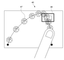
- FIG. 5 is a schematic diagram showing an example of setting the frame rate region and the frame rate of the image.
- a control GUI 40 capable of controlling the frame rate is displayed on the display unit 18.
- the user can set the frame rate region and the frame rate of the image by touching the display unit 18 on which the control GUI 40 is displayed.
- a basketball game is photographed by the image pickup device 10, and a goal 41 is displayed.
- FIG. 5 illustrates the moment when the basketball passes the goal.
- the user can set the frame rate region by tracing the expected route 43 (the line from the start point 44 to the end point 45) where the basketball is expected to pass with the finger 42.
- the user can set the frame rate of the image at the time of reproduction by controlling the speed of the finger 42 when tracing the expected path 43. That is, the frame rate of the image is controlled based on the input speed of the finger 42. For example, a frame rate set during shooting or playback based on the speed traced by the user's finger 42 (speed input by the user) and the speed of a specific subject during actual shooting or playback. Is calculated. The specific calculation method is shown below.
- the following parameters are used when obtaining the frame rate F of the controlled image.
- the actual speed of a specific subject is written as Vnow.
- the velocity of a specific subject input by the user is written as Vexpected.
- the frame rate of the image set by the user is written as Fplay.
- Vnow is acquired by the recognition unit 17.
- Vexpected is set by the frame rate setting unit 23.
- Fplay is a frame rate preset by user input.
- Vexpected is the velocity of a specific subject at each position of the predicted path 43. That is, the predicted path 43 can be said to be a set of points indicating each position of a specific subject.
- the speed of a specific subject input by the user at the start point 44 can be expressed as Vexpected (1).
- the velocity of a specific subject input by the user at the end point 45 can be expressed as Vexpected (n).
- the actual speed of a specific subject corresponding to Vexpected (1) can be expressed as Vnow (1).
- the actual velocity of a specific subject corresponding to Vexpected (n) can be expressed as Vnow (n).
- Equation 1 The processing of (Equation 1) is performed for each frame for the frame rate set at each position of the expected route, and the frame rate is controlled. For example, if you want to slow down the image 5 times at a predetermined position in the frame rate area, and if the number of frame rates during playback is 24, the number of frame rates of the image at the predetermined position is controlled to be 120. .. Further, during shooting, the above processing is executed every frame, and the frame rate is controlled.
- FIG. 6 is a schematic diagram showing an example of setting the frame rate region and the frame rate of the image when the rehearsal image was acquired.
- the control GUI 40 when the rehearsal image is acquired is taken as an example.
- the basketball 47 is ghost-displayed based on the expected route and frame rate input by the user.
- the ghost display indicates that a state in which a specific subject moves over a plurality of frames is virtually displayed according to an expected path which is a frame area and a set frame rate. For example, when ghosts are displayed overlapping, it indicates that the movement is slow, and when they are displayed at intervals, it indicates that the movement is fast. For example, in FIG. 5, since the ghosts of the basketball 47 near the goal 48 are displayed overlapping, the frame rate of the image is controlled to be small when the basketball 47 is near the goal 48.
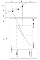
- FIG. 7 is a schematic diagram showing an example of the control GUI 50 for controlling the frame rate.
- the control GUI 50 displays a graph showing the frame rate on the vertical axis and the length from the start point on the horizontal axis.
- the user can adjust the frame rate in the frame rate region via the control GUI 50.
- the solid line 53 connecting the start point 51 to the end point 52 indicates the frame rate in the predicted route 43 from the start point 44 to the end point 45 input via the control GUI 40 shown in FIG.
- the dotted line 54 connecting the start point 51 and the end point 52 indicates a range in which the frame rate in the image can be changed. That is, the user can adjust the frame rate so as not to exceed the dotted line displayed on the control GUI 50.
- the frame rate indicated by the dotted line 54 is calculated based on the actual speed of the specific subject recognized by the recognition unit 17. For example, it may be calculated based on the actual speed of a specific subject at the time of shooting. Further, for example, it may be calculated based on the speed of a specific subject in the rehearsal image.
- the frame rate indicated by the dotted line 54 can be obtained by the above (Equation 1).
- the speed of the specific subject detected in advance by the recognition unit 17 in the rehearsal image is used as the predicted value of Vnow, which is the actual speed of the specific subject.
- the dotted line 54 corresponding to the frame rate obtained by this is displayed on the control GUI 50.
- control GUI 50 presents to the user when there is a rehearsal image and the solid line 53 exceeds the dotted line 54.
- the text may be presented to the user or may be presented by voice.
- control GUI 50 displays a marker 55 indicating the position of a specific subject on the predicted path. That is, the user can adjust the frame rate of a specific subject at the current position of the marker 55.
- control GUI 50 has a frame rate region and an image display unit 56 for displaying a specific subject.
- the image display unit 56 displays the predicted route 43 set by the control GUI 40 and the position (marker 55) of a specific subject passing through the predicted route. As a result, the user can control the frame rate of a specific subject at each position of the predicted path while simultaneously viewing the marker 55 on the predicted path and the graph. Further, the rehearsal image may be displayed on the image display unit 56.
- the determination unit 24 determines whether or not the distance between the specific subject and the frame rate region is equal to or less than the threshold value (step 104).
- the frame rate of the image is not controlled until the distance between the specific subject and the frame rate region is equal to or less than the threshold value.
- the recognition unit 17 recognizes the position of a specific subject and the frame rate at the position.
- the image sensor 13 is controlled by the control unit 15, and all images are captured at a high frame rate number.
- the shooting control unit 25 or the reproduction control unit 26 controls the frame rate of the image by performing a process of thinning out frames by using a conversion process or the like.
- the frame rate of the image may be controlled by adding frames by the shooting control unit 25 or the reproduction control unit 26 using an addition process or the like.
- the frame rate of the image may be controlled by performing a process of synthesizing the image or the like. Specifically, when the frame rate of an image is controlled in real time during shooting, the time interval for shooting each image for each frame is changed one after another by the shooting control unit 25.
- the control unit 15 can control the image sensor 13 to shoot at a set frame rate.
- the reproduction control unit 26 executes thinning and addition processing, so that the image is reproduced at the frame rate at the time of reproduction set in the frame rate setting unit 23.
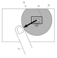
- FIG. 8 is a schematic diagram showing an example of the shape of the frame rate region.
- the user sets a circular frame rate region via the control GUI 70.
- the user can set the frame rate region by touching an arbitrary point and sliding the finger 71 (moving the finger in the touched state). For example, by touching the goal 72 and sliding the finger in a predetermined direction, a circular frame rate region 73 having a radius of the distance moved by the finger is set.
- FIG. 9 is a schematic diagram showing another example of the shape of the frame rate region.
- the entire stadium is photographed at a wide angle by the image pickup device 10.
- the user sets a rectangular frame rate region via the control GUI 70.
- the user can set the frame rate area by touching a predetermined position and sliding the finger 74.
- a rectangular frame rate region 75 having a diagonal line of the distance moved by the finger is set.
- the user can set the center coordinates of the set frame rate region 75. If not set by the user, the center coordinates of the frame rate region 75 are set to the center of gravity of the frame rate region. Further, in the case of the circular frame rate region 73, the center coordinates (any touched point) are set to the center.
- the method of setting the frame rate area is not limited.
- the coordinates and radius may be input numerically.
- the shape (boundary) of the frame rate region may be set by the user by tracing it with a finger.
- FIG. 10 is a schematic diagram showing an example of a frame rate control GUI in a frame rate region.
- a graph showing control of the frame rate in the frame rate region and a predicted route 81 corresponding to the graph are displayed on the control GUI 80.
- control unit 15 controls the frame rate of the image based on the position of the specific subject determined by the determination unit 24 and the position of the center coordinate 83 set in the frame rate area 82. .. Further, the user can control the frame rate corresponding to the path from the boundary of the frame rate region 82 to the center coordinate 83 of the frame rate region via the control GUI 80.
- the frame rate of the image is controlled so that the frame rate increases as the specific subject approaches the center coordinates from the boundary of the frame rate region.
- the normal frame rate is the normal frame rate when the image is reproduced. For example, when the image is reproduced at a frame rate number of 60, the frame rate number 60 is the normal frame rate.
- the user can use the control GUI 80 to determine the magnitude of the frame rate near the boundary of the frame rate region 82, the ratio of the distance from the boundary to the center coordinate 83 and the increase (decrease) of the frame rate, and the frame rate at the center coordinate 83. Set the size of.
- the frame rate at the position 84 (85) where the ratio of the distance between the center coordinate 83 and the frame rate region 82 is the same is set to be the same, one graph is displayed for the frame rate region 82. Will be done. That is, if the frame rate settings are different between the route 81 from the boundary of the frame rate region 82 to the center coordinate 83 and the route 87 from the center coordinate 83 to the boundary of the frame rate region 82, the two graphs are displayed. Is displayed.
- the method of controlling the frame rate is not limited. For example, the methods shown in FIGS. 11, 12, 13, and 14 described later may be used.
- 11 to 14 are schematic views showing an example of frame rate control.
- the vertical axis shows the frame rate and the horizontal axis shows the distance from the starting point.
- the determination unit 24 determines whether or not a specific subject has crossed the boundary of the frame rate region. For example, the determination unit 24 determines whether or not the center of gravity of a specific subject exceeds the frame rate region. When the center of gravity of a specific subject exceeds the frame rate region, the control unit 15 changes the frame rate to the frame rate shown in FIG.
- the frame rate of the image is changed stepwise as the specific subject approaches the center coordinates of the frame rate region.
- the frame rate is set so that the frame rate gradually increases as a specific subject approaches the center coordinates.
- the frame rate may be set so that the frame rate of the image gradually decreases as the specific subject moves away from the center coordinates.
- the user may be able to control at what stage the frame rate approaches the set value via the control GUI, or may be appropriately calculated by the control unit 15.
- the relationship between the distance and the frame rate as shown in FIG. 12 is recorded in advance in the recording unit 16 as a table, and the control unit 15 may control the frame rate of the image based on the table.
- the frame rate of the image is continuously changed as the specific subject approaches the center coordinates of the frame rate region.
- the frame rate is set so that the slope of the straight line becomes steeper as the specific subject approaches the center coordinates.
- the frame rate is set so that the inclination of the straight line becomes gentle as the specific subject moves away from the center coordinates.
- the user can control via the control GUI so that the slope of the straight line and the curve when approaching the value of the set frame rate becomes high or low. That is, the coefficients of the straight line or the curve are changed.
- the relationship between the distance and the frame rate as shown in FIG. 13 is recorded in advance in the recording unit 16 as a table, and the control unit 15 may control the frame rate of the image based on the table.
- the image pickup apparatus 10 recognizes a specific subject in the image. It is determined whether or not the distance between the recognized specific subject and the frame rate region for setting the frame rate of the image is equal to or less than the threshold value. This makes it possible to easily control the frame rate of the image.
- a method such as the RAMP effect that gradually changes the frame rate of a moving image for a scene that is desired to be impressed as a video expression may be used.
- a scene to be shot is determined in advance, rehearsals and the like are performed, and a target frame rate and a time until the frame rate is reached are set. In this case, it is difficult to shoot the desired moving image because the timing is accurately adjusted with respect to the movement of the object.
- the user can input the frame rate of a specific subject by tracing it along the expected path. This makes it easier to shoot, play, and edit images with more intuitive input than before.
- the image pickup apparatus 10 controls the frame rate of the image at the time of shooting and at the time of reproduction.
- the captured image may be transmitted to an external information processing device, and the frame rate of the image may be controlled by the information processing device.
- FIG. 15 is a block diagram showing a functional configuration example of the information processing apparatus.
- the information processing apparatus 100 includes a control unit 15, a recording unit 16, a recognition unit 17, a display unit 18, an output unit 19, and an operation unit 20.
- the information processing device 100 includes an editing device such as a PC or a smartphone, and a playback device such as a monitor.
- an image signal may be supplied by the image pickup device 10 and the frame rate may be controlled for the image signal.
- a signal for controlling the frame rate set by the editing device may be supplied to the playback device, and the playback device may control the frame rate according to the signal. Since each block executes the same processing as the block mounted on the image pickup apparatus 10, the description thereof will be omitted.
- the information processing device 100 is wirelessly or wiredly connected to the image pickup device 10 that captures an image via the output unit 19.
- the connection form between each device is not limited, and for example, wireless LAN communication such as WiFi and short-range wireless communication such as Bluetooth (registered trademark) can be used.
- the captured image signal or the reproduced image signal may be received from the image pickup apparatus 10 and the frame rate of the image signal received by the information processing apparatus 100 may be controlled.
- a reproduced image signal recorded in a recording device such as an SD (Secure Digital) card may be read.
- control the frame rate of the captured image signal or the reproduced image signal it is possible to control the frame rate of the captured image signal or the reproduced image signal.
- the control unit 15 performs frame rate thinning and addition processing on the recorded image, so that the image is reproduced at the set frame rate.
- a captured image or a reproduced image whose frame rate is controlled by the image pickup device 10 or the information processing device 100 may be displayed on the display unit of the external device.
- the frame rate is controlled according to the distance between a specific subject and the frame rate region.
- interpolation processing may be performed when the actual position during shooting of a specific subject and the position of the frame rate region deviate from each other.
- the interpolation process may be performed when the actual movement (path) of a specific subject during shooting and the path (expected path) of the set frame rate region deviate from each other.
- the control unit 15 uses nearest interpolation, secondary interpolation, etc., and the frame rate of the image. May be controlled.
- the frame rate of the image is controlled from the speed of a specific subject input by the user's finger.
- the user may enter a numerical value of the frame rate of the image without being limited to this.
- the image was taken and reproduced according to the set frame rate of the image. Not limited to this, the following calculation may be executed when the actual shooting and reproduction cannot be performed according to the frame rate set by the user.
- the frame rate is input according to the speed at which the user's finger moves.
- a button or the like on which the numerical value can be arbitrarily changed may be displayed on the control GUI.
- only one frame rate region is set.
- a plurality of frame rate areas may be set.
- a frame rate region containing two basket goals may be set.
- the control unit 15 may control the frame rate of the image based on the frame rate at which the specific subject is closer to the center coordinates of the frame rate region when the plurality of frame rate regions overlap.
- the control unit 15 may take a weighted average of the frame rates based on the distances between the center coordinates of the plurality of frame rate regions and a specific subject.
- the frame rate is controlled for sports such as basketball. Not limited to this, it may be used in any field.
- the wedding cake may be included in the frame rate area and controlled to be the set frame rate when a person approaches to cut the cake.
- FIG. 16 is a block diagram showing a hardware configuration example of the information processing apparatus 100.
- the information processing apparatus 100 includes a CPU 101, a ROM 102, a RAM 103, an input / output interface 105, and a bus 104 connecting these to each other.
- a display unit 106, an input unit 107, a storage unit 108, a communication unit 109, a drive unit 110, and the like are connected to the input / output interface 105.
- the display unit 106 is a display device using, for example, a liquid crystal display, an EL, or the like.
- the input unit 107 is, for example, a keyboard, a pointing device, a touch panel, or other operating device. When the input unit 107 includes a touch panel, the touch panel may be integrated with the display unit 106.
- the storage unit 108 is a non-volatile storage device, for example, an HDD, a flash memory, or other solid-state memory.
- the drive unit 110 is a device capable of driving a removable recording medium 111 such as an optical recording medium or a magnetic recording tape.
- the communication unit 109 is a modem, router, or other communication device for communicating with other devices that can be connected to a LAN, WAN, or the like.
- the communication unit 109 may communicate using either wired or wireless.
- the communication unit 109 is often used separately from the information processing device 100.
- Information processing by the information processing apparatus 100 having the hardware configuration as described above is realized by the cooperation between the software stored in the storage unit 108 or the ROM 102 or the like and the hardware resources of the information processing apparatus 100.
- the information processing method according to the present technology is realized by loading the program constituting the software stored in the ROM 102 or the like into the RAM 103 and executing the program.
- the program is installed in the information processing apparatus 100 via, for example, the recording medium 111.
- the program may be installed in the information processing apparatus 100 via a global network or the like.
- any non-transient storage medium that can be read by a computer may be used.
- An information processing device By linking a computer mounted on a communication terminal with another computer capable of communicating via a network or the like, an image pickup device, an information processing device, an information processing method, and a program related to this technology are executed, and related to this technology.
- An information processing device may be constructed.
- the image pickup device, the information processing device, the information processing method, and the program according to the present technology can be executed not only in a computer system composed of a single computer but also in a computer system in which a plurality of computers operate in conjunction with each other. ..
- the system means a set of a plurality of components (devices, modules (parts), etc.), and it does not matter whether or not all the components are in the same housing. Therefore, a plurality of devices housed in separate housings and connected via a network, and one device in which a plurality of modules are housed in one housing are both systems.
- the computer system executes the image pickup device, information processing device, information processing method, and program related to this technology, for example, recognition of a specific subject, frame rate setting, frame rate control, and the like are executed by a single computer. Includes both when it is done and when each process is performed by a different computer. Further, the execution of each process by a predetermined computer includes having another computer execute a part or all of the process and acquiring the result.
- the image pickup device, information processing device, information processing method, and program related to this technology can be applied to the configuration of cloud computing in which one function is shared by a plurality of devices via a network and jointly processed. It is possible.
- Each configuration of the frame rate area setting unit 22, the determination unit 24, the frame rate setting unit 23, etc., the control flow of the communication system, etc. described with reference to each drawing is merely an embodiment and does not deviate from the purpose of the present technology. It can be deformed arbitrarily within the range. That is, other arbitrary configurations, algorithms, and the like for implementing the present technology may be adopted.
- the effects described in the present disclosure are merely examples and are not limited, and other effects may be obtained.
- the description of the plurality of effects described above does not necessarily mean that the effects are exerted at the same time. It means that at least one of the above-mentioned effects can be obtained depending on the conditions and the like, and of course, there is a possibility that an effect not described in the present disclosure may be exhibited.
- this technology can also adopt the following configurations.
- a recognition unit that recognizes a specific subject in an image An image pickup apparatus including a determination unit for determining whether or not the distance between the recognized specific subject and a frame rate region for setting a frame rate of an image is equal to or less than a threshold value.
- An image pickup apparatus including a frame rate setting unit for setting the frame rate of the image.
- An image pickup device provided with a shooting control unit.
- the image pickup apparatus according to (2) further When the determination unit determines that the distance between the specific subject and the set frame rate region is equal to or less than the threshold value, the determination unit controls the image to be reproduced at the set frame rate.
- An image pickup device provided with a playback control unit.
- the frame rate area setting unit is an image pickup device that sets the frame rate area as a point.
- the frame rate area setting unit is an image pickup device that sets the frame rate area as a line.
- the frame rate area setting unit is an image pickup device that sets the frame rate area as a region having a predetermined range.
- the image pickup apparatus sets a plurality of the frame rate areas and sets the frame rate area.
- the shooting control unit determines the set frame rate.
- the image pickup apparatus sets a plurality of the frame rate areas and sets the frame rate area.
- the reproduction control unit determines the set frame rate.
- An image pickup device that controls the reproduction of the image.
- the image pickup apparatus (11) The image pickup apparatus according to (4).
- the frame rate area setting unit sets the frame rate area as an area having a predetermined range, and sets the frame rate area as an area.
- the shooting control unit controls to shoot the image at the set frame rate when the determination unit determines that the specific subject is within the range of the set frame rate region.
- Imaging device. (12) The image pickup apparatus according to (5).
- the frame rate area setting unit sets the frame rate area as an area having a predetermined range, and sets the frame rate area as an area.
- the reproduction control unit controls to reproduce the image at the set frame rate when the determination unit determines that the specific subject is within the range of the set frame rate region.
- Imaging device (12) The image pickup apparatus according to (5).
- the frame rate area setting unit sets the frame rate area as an area having a predetermined range, and sets the frame rate area as an area.
- the reproduction control unit controls to reproduce the image at the set frame rate when the determination unit determines that the specific subject is within the range of the set frame rate
- the image pickup apparatus according to (2), further Equipped with an operation unit that accepts user operations The frame rate area setting unit is an image pickup device that sets the frame rate area according to a user's operation on the operation unit.
- the image pickup apparatus according to (3), further Equipped with an operation unit that accepts user operations The frame rate setting unit is an image pickup device that sets the frame rate of the image according to the user's operation on the operation unit.
- the frame rate setting unit is an image pickup device that sets the frame rate so that the frame rate changes stepwise according to the distance between the specific subject and the frame rate region. (16) The image pickup apparatus according to (3).
- the frame rate setting unit is an image pickup device that sets the frame rate so that the frame rate changes continuously according to the distance between the specific subject and the frame rate region.
- a recognition unit that recognizes a specific subject in an image
- An information processing device including a determination unit for determining whether or not the distance between the recognized specific subject and the frame rate region for setting the frame rate of an image is equal to or less than a threshold value.
- a step of recognizing a specific subject in an image A program that causes a computer system to perform a step of determining whether or not the distance between the recognized specific subject and the frame rate area for setting the frame rate of an image is equal to or less than a threshold value.
Landscapes
- Engineering & Computer Science (AREA)
- Multimedia (AREA)
- Signal Processing (AREA)
- Human Computer Interaction (AREA)
- Physics & Mathematics (AREA)
- General Physics & Mathematics (AREA)
- Theoretical Computer Science (AREA)
- Computer Vision & Pattern Recognition (AREA)
- Studio Devices (AREA)
Priority Applications (3)
| Application Number | Priority Date | Filing Date | Title |
|---|---|---|---|
| CN202180058337.6A CN116076083A (zh) | 2020-08-07 | 2021-07-26 | 成像装置,信息处理装置,信息处理方法和程序 |
| US18/018,990 US12457404B2 (en) | 2020-08-07 | 2021-07-26 | Imaging apparatus, information processing apparatus, information processing method, and program |
| JP2022541438A JP7740245B2 (ja) | 2020-08-07 | 2021-07-26 | 撮像装置、情報処理装置、情報処理方法、及びプログラム |
Applications Claiming Priority (2)
| Application Number | Priority Date | Filing Date | Title |
|---|---|---|---|
| JP2020134830 | 2020-08-07 | ||
| JP2020-134830 | 2020-08-07 |
Publications (1)
| Publication Number | Publication Date |
|---|---|
| WO2022030275A1 true WO2022030275A1 (ja) | 2022-02-10 |
Family
ID=80117335
Family Applications (1)
| Application Number | Title | Priority Date | Filing Date |
|---|---|---|---|
| PCT/JP2021/027475 Ceased WO2022030275A1 (ja) | 2020-08-07 | 2021-07-26 | 撮像装置、情報処理装置、情報処理方法、及びプログラム |
Country Status (4)
| Country | Link |
|---|---|
| US (1) | US12457404B2 (https=) |
| JP (1) | JP7740245B2 (https=) |
| CN (1) | CN116076083A (https=) |
| WO (1) | WO2022030275A1 (https=) |
Citations (1)
| Publication number | Priority date | Publication date | Assignee | Title |
|---|---|---|---|---|
| JP2011010276A (ja) * | 2009-05-22 | 2011-01-13 | Sanyo Electric Co Ltd | 画像再生装置及び撮像装置 |
Family Cites Families (4)
| Publication number | Priority date | Publication date | Assignee | Title |
|---|---|---|---|---|
| JP4847165B2 (ja) | 2006-03-09 | 2011-12-28 | 株式会社日立製作所 | 映像記録再生方法及び映像記録再生装置 |
| JP5234119B2 (ja) | 2011-01-20 | 2013-07-10 | カシオ計算機株式会社 | 撮像装置、撮像処理方法及びプログラム |
| CN105635624B (zh) * | 2014-10-27 | 2019-05-03 | 华为技术有限公司 | 视频图像的处理方法、设备及系统 |
| CN110135246B (zh) * | 2019-04-03 | 2023-10-20 | 平安科技(深圳)有限公司 | 一种人体动作的识别方法及设备 |
-
2021
- 2021-07-26 WO PCT/JP2021/027475 patent/WO2022030275A1/ja not_active Ceased
- 2021-07-26 CN CN202180058337.6A patent/CN116076083A/zh active Pending
- 2021-07-26 US US18/018,990 patent/US12457404B2/en active Active
- 2021-07-26 JP JP2022541438A patent/JP7740245B2/ja active Active
Patent Citations (1)
| Publication number | Priority date | Publication date | Assignee | Title |
|---|---|---|---|---|
| JP2011010276A (ja) * | 2009-05-22 | 2011-01-13 | Sanyo Electric Co Ltd | 画像再生装置及び撮像装置 |
Also Published As
| Publication number | Publication date |
|---|---|
| JPWO2022030275A1 (https=) | 2022-02-10 |
| US12457404B2 (en) | 2025-10-28 |
| JP7740245B2 (ja) | 2025-09-17 |
| CN116076083A (zh) | 2023-05-05 |
| US20230345107A1 (en) | 2023-10-26 |
Similar Documents
| Publication | Publication Date | Title |
|---|---|---|
| US11012614B2 (en) | Image processing device, image processing method, and program | |
| CN101415076B (zh) | 构图判定设备、构图判定方法 | |
| KR101679290B1 (ko) | 영상 처리 방법 및 장치 | |
| US9307153B2 (en) | Method and apparatus for previewing a dual-shot image | |
| CN102957860B (zh) | 图像处理设备和处理图像的方法 | |
| US20120275648A1 (en) | Imaging device and imaging method and program | |
| US20150070526A1 (en) | Display control device, display control method, and program | |
| JP4618166B2 (ja) | 画像処理装置、画像処理方法、およびプログラム | |
| RU2599260C2 (ru) | Устройство обработки цифровых изображений и способ управления им | |
| US20120098946A1 (en) | Image processing apparatus and methods of associating audio data with image data therein | |
| US20200099853A1 (en) | Electronic device, and region selection method | |
| CN107395957A (zh) | 拍照方法、装置、存储介质及电子设备 | |
| JP2014017665A (ja) | 表示制御装置、表示制御装置の制御方法、プログラムおよび記録媒体 | |
| JP2007251429A (ja) | 動画撮影装置及びズーム調整方法 | |
| JP5440588B2 (ja) | 構図判定装置、構図判定方法、プログラム | |
| EP4503590A1 (en) | Shooting method, apparatus, electronic device and medium | |
| JP7740245B2 (ja) | 撮像装置、情報処理装置、情報処理方法、及びプログラム | |
| JP2023133348A (ja) | 撮影プログラム、情報処理装置、および方法 | |
| JP2021002803A (ja) | 画像処理装置、その制御方法、プログラム | |
| CN115550536A (zh) | 图像处理方法、图像处理器及电子设备 | |
| JP7612627B2 (ja) | 主被写体判定装置、撮像装置、主被写体判定方法、及びプログラム | |
| WO2022158201A1 (ja) | 画像処理装置、画像処理方法、プログラム | |
| KR20120085476A (ko) | 영상 재생 방법, 영상 재생 장치, 및 컴퓨터 판독가능 저장매체 | |
| JP2016010079A (ja) | 表示制御装置 |
Legal Events
| Date | Code | Title | Description |
|---|---|---|---|
| 121 | Ep: the epo has been informed by wipo that ep was designated in this application |
Ref document number: 21854051 Country of ref document: EP Kind code of ref document: A1 |
|
| ENP | Entry into the national phase |
Ref document number: 2022541438 Country of ref document: JP Kind code of ref document: A |
|
| NENP | Non-entry into the national phase |
Ref country code: DE |
|
| 122 | Ep: pct application non-entry in european phase |
Ref document number: 21854051 Country of ref document: EP Kind code of ref document: A1 |
|
| WWG | Wipo information: grant in national office |
Ref document number: 18018990 Country of ref document: US |