WO2022030222A1 - 眼科装置 - Google Patents
眼科装置 Download PDFInfo
- Publication number
- WO2022030222A1 WO2022030222A1 PCT/JP2021/026780 JP2021026780W WO2022030222A1 WO 2022030222 A1 WO2022030222 A1 WO 2022030222A1 JP 2021026780 W JP2021026780 W JP 2021026780W WO 2022030222 A1 WO2022030222 A1 WO 2022030222A1
- Authority
- WO
- WIPO (PCT)
- Prior art keywords
- eye
- inspected
- inspection
- water content
- light
- Prior art date
- Legal status (The legal status is an assumption and is not a legal conclusion. Google has not performed a legal analysis and makes no representation as to the accuracy of the status listed.)
- Ceased
Links
Images
Classifications
-
- A—HUMAN NECESSITIES
- A61—MEDICAL OR VETERINARY SCIENCE; HYGIENE
- A61B—DIAGNOSIS; SURGERY; IDENTIFICATION
- A61B3/00—Apparatus for testing the eyes; Instruments for examining the eyes
- A61B3/10—Objective types, i.e. instruments for examining the eyes independent of the patients' perceptions or reactions
-
- A—HUMAN NECESSITIES
- A61—MEDICAL OR VETERINARY SCIENCE; HYGIENE
- A61B—DIAGNOSIS; SURGERY; IDENTIFICATION
- A61B3/00—Apparatus for testing the eyes; Instruments for examining the eyes
- A61B3/18—Arrangement of plural eye-testing or -examining apparatus
-
- G—PHYSICS
- G01—MEASURING; TESTING
- G01N—INVESTIGATING OR ANALYSING MATERIALS BY DETERMINING THEIR CHEMICAL OR PHYSICAL PROPERTIES
- G01N21/00—Investigating or analysing materials by the use of optical means, i.e. using sub-millimetre waves, infrared, visible or ultraviolet light
- G01N21/17—Systems in which incident light is modified in accordance with the properties of the material investigated
- G01N21/25—Colour; Spectral properties, i.e. comparison of effect of material on the light at two or more different wavelengths or wavelength bands
- G01N21/31—Investigating relative effect of material at wavelengths characteristic of specific elements or molecules, e.g. atomic absorption spectrometry
- G01N21/35—Investigating relative effect of material at wavelengths characteristic of specific elements or molecules, e.g. atomic absorption spectrometry using infrared light
- G01N21/3554—Investigating relative effect of material at wavelengths characteristic of specific elements or molecules, e.g. atomic absorption spectrometry using infrared light for determining moisture content
-
- G—PHYSICS
- G01—MEASURING; TESTING
- G01N—INVESTIGATING OR ANALYSING MATERIALS BY DETERMINING THEIR CHEMICAL OR PHYSICAL PROPERTIES
- G01N21/00—Investigating or analysing materials by the use of optical means, i.e. using sub-millimetre waves, infrared, visible or ultraviolet light
- G01N21/17—Systems in which incident light is modified in accordance with the properties of the material investigated
- G01N21/25—Colour; Spectral properties, i.e. comparison of effect of material on the light at two or more different wavelengths or wavelength bands
- G01N21/31—Investigating relative effect of material at wavelengths characteristic of specific elements or molecules, e.g. atomic absorption spectrometry
- G01N21/35—Investigating relative effect of material at wavelengths characteristic of specific elements or molecules, e.g. atomic absorption spectrometry using infrared light
- G01N21/359—Investigating relative effect of material at wavelengths characteristic of specific elements or molecules, e.g. atomic absorption spectrometry using infrared light using near infrared light
Definitions
- the present disclosure relates to an ophthalmic apparatus for acquiring information on the amount of water on the surface of an eyeball using light.
- a dry eye inspection device that inspects the dry eye of the eye to be inspected without contact
- a dry eye inspection device that allows the user to observe the tear film layer of the inspected eye by using optical interference technology.
- optical interference technology the configuration of a device using optical interference technology is complicated.
- Patent Document 1 a method of inspecting an inspected eye in a non-contact manner using light is attempted for the diagnosis of corneal edema occurring inside the cornea of the inspected eye.
- the inspection device of Patent Document 1 switches between moisture measurement infrared light and reference infrared light to irradiate the cornea, and based on the intensity of the reflected light of each light, provides information useful for diagnosing corneal edema. get.
- the optical axis for irradiating light and the optical axis for receiving light to which the reflected light from the cornea is guided extend in the line-of-sight direction of the eye to be inspected and are coaxial.
- An ophthalmic device that has both the function of performing a non-contact inspection of the water content of the eye to be inspected without using optical interference technology and the function of inspecting the eye characteristics of the eye to be inspected other than the water content has yet been realized. Not in. Further, an ophthalmologic device capable of efficiently and appropriately performing both a water content test and an eye characteristic test is a very useful device.
- a typical object of the present disclosure is to provide an ophthalmic apparatus capable of appropriately performing both a water content test and an eye characteristic test.
- the ophthalmologic apparatus provided by a typical embodiment in the present disclosure is an ophthalmologic apparatus for inspecting an eye to be inspected, and is linearly connected to a moisture content inspection unit for inspecting the water content of the surface of the eyeball of the eye to be inspected and the apparatus.
- a moisture content inspection unit for inspecting the water content of the surface of the eyeball of the eye to be inspected and the apparatus.
- the water content inspection unit includes a fixation target projection optical system for projecting a fixation target for fixing the eye to be inspected onto the eye to be inspected, and a control unit, and the water content inspection unit shows a maximum value of absorption loss due to water.
- the surface of the eyeball of the eye to be inspected is irradiated with a moisture measurement light source that emits moisture measurement light for moisture content inspection, including a moisture measurement wavelength corresponding to the infrared wavelength, and moisture measurement light emitted by the moisture measurement light source.
- the control unit includes an irradiation optical system for moisture and a light receiving optical system for moisture that guides the reflected light of the moisture measurement light from the surface of the eyeball and causes the receiver for moisture measurement to receive light.
- Each of the inspection by the inspection unit and the inspection by the eye characteristic inspection unit is performed in a state where the fixation target is projected onto the eye to be inspected by the fixation target projection optical system.
- both the water content test and the eye characteristic test are properly performed.
- the ophthalmic apparatus exemplified in the present disclosure includes a water content inspection unit, an eye characteristic inspection unit, an fixation target projection optical system, and a control unit.
- the water content inspection unit inspects the water content on the surface of the eyeball of the eye to be inspected.
- the eye characteristic inspection unit inspects the eye characteristics of the eye to be inspected, which is different from the water content, with the inspection axis extending linearly from the device aligned with the eye to be inspected.
- the fixation target projection optical system projects an fixation target that makes the subject to be fixed, in a state where the optical axis extending from the device is aligned with the inspection axis.
- the control unit controls the ophthalmic appliance.
- the moisture content inspection unit includes a moisture measurement light source, an irradiation optical system for moisture, and a light receiving optical system for moisture.
- the moisture measurement light source emits moisture measurement light for moisture content inspection, which includes a moisture measurement wavelength corresponding to an infrared wavelength at which the absorption loss amount due to water shows a maximum value.
- the moisture irradiation optical system irradiates the surface of the eyeball of the eye to be inspected with the moisture measurement light emitted by the moisture measurement light source.
- the moisture receiving optical system guides the reflected light of the moisture measuring light from the surface of the eyeball and causes the moisture measuring receiver to receive the light. Both the inspection by the water content inspection unit and the inspection by the eye characteristic inspection unit are performed with the fixation target projected onto the eye to be inspected by the fixation target projection optical system.
- both the water content test of the eyeball surface of the eye to be inspected and the test of eye characteristics different from the water content are performed. Therefore, the examination efficiency of the eye to be inspected is improved.
- the ophthalmic apparatus according to the present disclosure performs a water content test by using a water content measurement light including a water content measurement wavelength having a large absorption loss due to water. Therefore, the water content test is performed with a simpler configuration than when the optical interference technique is used.
- the inspection by the water content inspection unit and the inspection by the eye characteristic inspection unit are both performed in a state where the fixation target is projected onto the eye to be inspected by the fixation target projection optical system.
- the subject can undergo a water content test and an eye characteristic test without changing the line-of-sight direction. Further, since at least a part of the fixation target projection optical system is shared by the water content test and the eye characteristic test, the device configuration is also simplified. Therefore, both tests are properly performed.
- the moisture measurement light source may emit moisture measurement light including a moisture measurement wavelength and a reference wavelength which is an infrared wavelength in which the amount of absorption loss due to water is smaller than the moisture measurement wavelength.
- the control unit may acquire information on the amount of water on the surface of the eyeball based on the difference or ratio between the intensity of the moisture measurement wavelength and the intensity of the reference wavelength of the reflected light received by the moisture measurement receiver. Since the reference wavelength is less likely to be absorbed by water than the moisture measurement wavelength, it is less susceptible to the influence of water. Therefore, the water content on the surface of the eyeball is quantified with high accuracy by acquiring the water content information based on the difference or ratio between the intensity of the water content measurement wavelength and the intensity of the reference wavelength.
- control unit can also acquire information on the amount of water content based on the intensity of the water content measurement wavelength without using the intensity of the reference wavelength in the reflected light. Even in this case, a qualitative measurement result of the water content on the surface of the eyeball can be appropriately obtained.
- the control unit determines the amount of water on the surface of the eyeball based on the intensity of the diffusely reflected light received by the receiver for measuring moisture among the reflected light of the moisture measurement light from the surface of the eyeball including the positively reflected light and the diffusely reflected light. Information may be obtained.
- the water content of the surface of the eyeball (including tissues near the surface and water) shows a strong correlation with the intensity of diffuse reflected light of the water content measurement light. Therefore, if the diffusely reflected light from the tissue is buried in the specularly reflected light, it is difficult to properly obtain information on the water content of the tissue. Therefore, by using the intensity of the diffusely reflected light among the reflected light including the normal reflected light and the diffusely reflected light, the information on the amount of water on the surface of the eyeball can be obtained in a non-contact manner and with higher accuracy.
- At least one of the irradiation optical axis of the moisture irradiation optical system and the light receiving optical axis of the moisture receiving optical system extending linearly between the device and the eye to be inspected may be inclined with respect to the inspection axis.
- the specularly reflected light of the moisture measurement light from the surface of the eyeball is incident on the moisture measurement receiver as compared with the case where both the irradiation optical axis and the light receiving optical axis of the moisture content inspection unit coincide with the inspection axis. Can be easily suppressed.
- the irradiation optical axis of the moisture irradiation optical system and the light receiving optical axis of the moisture receiving optical system one may coincide with the inspection axis and the other may be inclined with respect to the inspection axis.
- the subject undergoes a water content test while staring at the fixation target projected along the inspection axis. Therefore, of the irradiation optical axis and the light receiving optical axis, the optical axis that coincides with the inspection axis tends to coincide with the apex of the cornea of the eye to be inspected.
- the specularly reflected light from the apex of the cornea toward the device side along the inspection axis tends to be only the specularly reflected light of the light radiated to the apex along the inspection axis. Therefore, by aligning one of the irradiation optical axis and the light receiving optical axis with the inspection axis and inclining the other with respect to the inspection axis, there is a possibility that the specularly reflected light of the moisture measurement light is received by the moisture receiving optical system. , Decreas properly. Further, the specularly reflected light of the moisture measurement light by the iris of the eye to be inspected is also difficult to be received by the moisture light receiving optical system.
- the angle formed by the irradiation optical axis and the light receiving optical axis may be 40 degrees or more, more preferably 60 degrees or more. You may. In this case, the possibility that the specularly reflected light of the moisture measurement light by the surface of the eyeball is received by the moisture receiving optical system is further reduced.
- the ophthalmic apparatus may include a ring index projection optical system that projects a ring index onto the cornea of the eye to be inspected.
- the optical axis inclined with respect to the inspection axis is referred to as the inclined optical axis.
- the angle of inclination of the ring index projection optical system with respect to the inspection axis and the angle of the tilted optical axis of the water content inspection unit with respect to the inspection axis when viewed from the position of the eye to be inspected may be different. In this case, the position of the ring index projection optical system and the position of the optical system of the water content inspection unit are unlikely to interfere with each other. Therefore, a plurality of optical systems are appropriately arranged in the device.
- the irradiation optical axis may coincide with the inspection axis, and the light receiving optical axis may be tilted with respect to the inspection axis.
- the moisture measurement light is likely to be applied to the apex of the cornea of the eye to be inspected regardless of the change in the distance between the device and the eye to be inspected (so-called working distance).
- the light receiving optical system for moisture can receive diffuse reflected light from the eye to be inspected regardless of the distance between the device and the eye to be inspected. Therefore, the water content test is performed more appropriately.
- the light receiving optical axis may coincide with the inspection axis, and the irradiation optical axis may be inclined with respect to the inspection axis. Further, both the irradiation optical axis and the light receiving optical axis of the water content inspection unit may be inclined with respect to the inspection axis. Even in this case, by appropriately adjusting the arrangement of the irradiation optical axis and the light receiving optical axis with respect to the eye to be inspected, the possibility that the specularly reflected light of the moisture measurement light is received by the moisture receiving optical system is reduced.
- the irradiation optical axis and the light receiving optical axis extending between the water content inspection unit and the eye to be inspected can be tilted with respect to the inspection axis while being coaxial with each other by using a half mirror or the like.
- the specularly reflected light of the moisture measurement light is received by the moisture light receiving optical system by aligning the irradiation optical axis and the light receiving optical axis near the apex of the cornea of the eye to be inspected. The chances are reduced.
- the eye characteristic inspection unit may include an objective lens arranged so that the optical axis coincides with the inspection axis.
- an optical path synthesizer having one of the optical axis of the eye characteristic inspection unit and one of the irradiation optical axis and the light receiving optical axis of the water content inspection unit coaxial with each other is placed on the inspection axis between the objective lens and the eye to be inspected. You may prepare. If the optical path synthesizing unit is arranged on the side farther from the eye to be inspected than the objective lens, aberrations and stray light in the eye characteristic inspection unit may increase. On the other hand, by arranging the optical path synthesizing unit between the objective lens and the eye to be inspected, the two optical axes are appropriately coaxial with each other while the influence of aberration or the like is suppressed.
- a cover glass having no optical power may be arranged on the inspection axis between the objective lens and the eye to be inspected.
- the optical path synthesizer may be provided on the inspection axis between the objective lens and the cover glass. In this case, the possibility of dust or the like invading the moisture content inspection unit is appropriately suppressed by the cover glass.
- the eye characteristic inspection unit irradiates the eye to be inspected with an eye characteristic inspection light having a wavelength different from that of the moisture measurement light, and receives the reflected light of the eye characteristic inspection light from the inspected eye to receive the reflected light of the eye characteristic inspection light of the inspected eye.
- An inspection may be performed. In this case, the influence of the light of the other inspection unit on each inspection of the water content inspection unit and the eye characteristic inspection unit is appropriately suppressed.
- the control unit may be able to execute a simultaneous inspection mode in which the inspection by the water content inspection unit and the inspection by the eye characteristic inspection unit are performed in parallel. In this case, since it is not necessary to separately perform the water content test and the eye characteristic test, the efficiency of the test is further improved. As described above, when the wavelength of the moisture measurement light and the wavelength of the eye characteristic test light are different wavelengths, the accuracy of each test is guaranteed even if the simultaneous test mode is executed.
- this disclosure exemplifies a case where an optical power measuring unit that inspects the refractive power of the eye to be inspected is adopted as an eye characteristic testing unit mounted on an ophthalmic device together with a water content testing unit.
- the eye characteristic inspection unit exemplified in the present disclosure can measure the corneal shape of the eye to be inspected as well as the refractive power of the eye to be inspected.
- the eye characteristic inspection unit is not limited to the eye refractive power measurement unit.
- the eye characteristic inspection unit may be an axial length measuring unit that measures the axial length of the eye to be inspected, or a non-contact intraocular pressure measuring unit that measures the intraocular pressure of the eye to be inspected in a non-contact manner. May be good.
- the "examination of the eye characteristics of the eye to be inspected different from the water content” includes imaging of the eye tissue of the inspected eye. Therefore, the eye characteristic inspection unit may be an OCT unit that captures a tomographic image of a tissue according to the principle of optical coherence tomography, or may be a scanning laser ophthalmoscope (SLO), a fundus camera, or the like. Further, the ophthalmic apparatus may include a plurality of eye characteristic inspection units for inspecting different eye characteristics.
- the control unit may detect the timing when the eye to be inspected opens the eye (for example, the timing when blinking is performed, etc.).
- the control unit may output information on the degree of dry eye of the eye to be inspected based on the elapsed time after the eye to be inspected opens and the information on the amount of water acquired by the water content inspection unit. In this case, useful information about dry eye is output based on the timing when the eye to be inspected opens the eye.
- the ophthalmic apparatus may include an anterior ocular segment imaging unit for photographing the anterior segment of the eye to be inspected. Even if the control unit detects the timing when the eye to be inspected opens the eye by performing known image processing or the like on the image of the anterior eye portion of the eye to be inspected continuously taken by the anterior eye part photographing unit. good.
- the control unit detects the timing when the eye to be inspected opens the eye by performing known image processing or the like on the image of the anterior eye portion of the eye to be inspected continuously taken by the anterior eye part photographing unit. good.
- information on the water content of the eyelid, not the surface of the eyeball is acquired by the water content inspection unit, so that the measured water content changes significantly compared to when the eye is open. .. Therefore, even if the control unit detects the timing when the water content measured by the water content inspection unit suddenly changes (for example, the timing when the water content suddenly increases) as the timing when the eye to be inspected opens the eye. good.
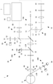
- the ophthalmic appliance 1 can both inspect the water content of the eyeball surface of the eye E to be inspected and the eye characteristics of the eye E to be inspected different from the water content.
- the ophthalmic apparatus 1 includes an eye characteristic inspection unit 10, a water content inspection unit 30, a fixation target projection optical system 50, a ring index projection optical system 65, a working distance index projection optical system 66, an observation optical system 70, and a control unit 80. Be prepared.
- the eye characteristic inspection unit 10 inspects the eye characteristics of the eye to be inspected E, which is different from the water content, in a state where the inspection axis EO is aligned with the eye to be inspected E.
- the eye characteristic inspection unit 10 of the present embodiment is an eye refractive power measuring unit that inspects the refractive power of the eye to be inspected E.
- the ophthalmic appliance 1 of the present embodiment can also measure the corneal shape of the eye E to be inspected.
- the eye characteristic inspection unit 10 is not limited to the eye refractive power measuring unit.
- the eye characteristic inspection unit 10 of the present embodiment includes a projection optical system 10A for eye characteristics and a light receiving optical system 10B for eye characteristics.
- the projection optical system 10A for eye characteristics projects a measurement index on the fundus of the eye E to be inspected through the central part of the pupil of the eye E to be inspected.
- the projection optical system 10A for eye characteristics includes an eye characteristic inspection light source 11, a relay lens 12, a hole mirror 13, and an objective lens 2 on the inspection optical axis L1 of the eye characteristic inspection unit 10.
- the inspection optical axis L1 of the eye characteristic inspection unit 10 coincides with the inspection axis EO of the ophthalmic apparatus 1. That is, various optical systems are arranged so that the optical axis of the objective lens 2 coincides with the inspection axis EO of the ophthalmic apparatus 1.
- the eye characteristic inspection light source 11 emits an eye characteristic inspection light for inspecting (measuring) eye characteristics (in this embodiment, the refractive power of the eye to be inspected E).
- the eye characteristic inspection light source 11 of the present embodiment is an SLD, and emits an eye characteristic inspection light having a wavelength of about 875 nm.
- the eye characteristic inspection light source 11 has a positional relationship optically conjugate with the fundus of the emmetropic eye. Further, the opening of the hole mirror 13 has a positional relationship optically conjugate with the pupil of the eye E to be inspected.
- the light receiving optical system 10B for eye characteristics takes out the fundus reflected light reflected from the fundus of the eye to be inspected in a ring shape through the peripheral portion of the pupil, and causes a two-dimensional photographing element to capture a ring-shaped fundus reflection image.
- the light receiving optical system 10B for eye characteristics shares the objective lens 2 and the hole mirror 13 with the projection optical system 10A for eye characteristics. Further, the light receiving optical system 10B for eye characteristics has a relay lens 16, a total reflection mirror 17, a light receiving aperture 18, and a relay lens 16 on the optical axis in the reflection direction of the hole mirror 13 (that is, on the optical axis branched by the hole mirror 13).
- the ring lens 20 includes a lens portion formed in a ring shape and a light-shielding portion formed in a region other than the lens portion.
- the ring lens 20 has a positional relationship optically conjugate with the pupil of the eye E to be inspected.
- the output from the two-dimensional photographing element 22 is input to the control unit 80.
- the projection optical system 10A for eye characteristics may project a ring-shaped measurement index from the peripheral portion of the pupil to the fundus.
- the light receiving optical system 10B for eye characteristics may take out the fundus reflected light from the center of the pupil and cause the two-dimensional photographing element 22 to receive the ring-shaped fundus reflected light.
- an intermittent ring image for example, a plurality of point images arranged in a substantially ring shape
- the water content inspection unit 30 inspects the water content on the surface of the eyeball of the eye E to be inspected (measurement of the water content in this embodiment).
- the moisture content inspection unit 30 includes a moisture measurement light source 3, an irradiation optical system for moisture 30A, and a light receiving optical system 30B for moisture.
- the moisture measurement light source 3 emits moisture measurement light, which is light for checking the moisture content.
- the moisture irradiation optical system 30A irradiates the eyeball surface (cornea in the present embodiment) of the eye E to be inspected with the moisture measurement light emitted by the moisture measurement light source 3.
- the water-receiving optical system 30B causes the water-receiving receiver 5 to receive the reflected light of the water-measured light from the surface of the eyeball of the eye E to be inspected.
- the wavelength of the moisture measurement light emitted by the moisture measurement light source 3 includes a predetermined moisture measurement wavelength.
- the water content measurement wavelength is a wavelength corresponding to the infrared wavelength at which the amount of absorption loss due to water shows a maximum value.
- the wavelength corresponding to the maximum value may be, for example, a wavelength within a range in which the difference from the wavelength showing the maximum value is equal to or less than the threshold value.
- the wavelength of the moisture measurement light in the present embodiment also includes a reference wavelength.
- the reference wavelength is an infrared wavelength in which the amount of absorption loss due to water is smaller than the water content measurement wavelength (that is, the infrared wavelength in which the influence of the amount of water on the irradiation site of the water content measurement light is smaller than the water content measurement wavelength).
- the control unit 80 obtains information on the amount of water on the surface of the eyeball based on the difference or ratio between the intensity of the moisture measurement wavelength and the intensity of the reference wavelength of the reflected light received by the moisture measurement receiver 5. get. Therefore, the water content on the surface of the eyeball is quantified with high accuracy.
- the moisture measurement light source 3 of the present embodiment includes a light source 3A that emits moisture measurement light including a moisture measurement wavelength and a light source 3B that emits moisture measurement light including a reference wavelength.
- a light source 3A that emits moisture measurement light including a moisture measurement wavelength
- a light source 3B that emits moisture measurement light including a reference wavelength.
- LEDs or the like can be used as the light sources 3A and 3B.
- the infrared region (specifically, the near infrared region) having a wavelength of 700 nm or more in which the absorption coefficient of hemoglobin becomes small is defined as the moisture measurement wavelength and reference. Used as a wavelength.
- the absorption coefficient by water that is, the amount of absorption loss
- the amount of water that absorbs the light of the water content measurement wavelength is effectively measured.
- the transmission distance of light from the surface of the eyeball changes depending on the wavelength at which the absorption coefficient by water reaches the maximum value. For example, light having a wavelength of about 1450 nm is transmitted to a depth of about 1000 ⁇ m from the surface of the cornea. Light with a wavelength of about 1900 nm is transmitted from the surface of the cornea to a depth of about 200 ⁇ m.
- the moisture measurement wavelength of this embodiment is set to a wavelength including 1450 nm. However, the moisture measurement wavelength may be changed depending on the application of the ophthalmic appliance 1 and the like.
- the water content measurement wavelength may be set to a wavelength including 1900 nm.
- a plurality of moisture measurement wavelengths for example, a wavelength including 1450 nm and a wavelength including 1900 nm may be set. Needless to say, the same effect can be obtained even if the wavelength value shown in the present embodiment is slightly changed.
- the reference wavelength is set to an infrared wavelength in which the amount of absorption loss due to water is smaller than the moisture measurement wavelength.
- the absorption coefficient by water is small in the range of 700 nm or more at about 940 nm and about 1270 nm. Therefore, the reference wavelength of this embodiment is set to a wavelength including 1270 nm as an example.
- the wavelength including 1270 nm is different from the wavelength of the eye characteristic test light and also different from the wavelength of the light (970 nm) emitted by the ring index projection optical system 65 and the working distance index projection optical system 66, which will be described later.
- the reference wavelength may be changed to another value (for example, 940 nm).
- the wavelength of light is different. Therefore, it is appropriately suppressed that the light of the other inspection unit affects each inspection of the eye characteristic inspection unit 10 and the water content inspection unit 30.
- the water content of the surface of the eyeball shows a strong correlation with the intensity of the diffuse reflected light of the water content measurement light. Therefore, if the diffusely reflected light from the tissue is buried in the specularly reflected light, it is difficult to properly obtain information on the water content of the tissue. Therefore, by using the intensity of the diffusely reflected light among the reflected light including the normal reflected light and the diffusely reflected light, the information on the amount of water on the surface of the eyeball can be obtained in a non-contact manner and with higher accuracy.
- the ophthalmic appliance 1 of the present embodiment includes an optical system in which specularly reflected light is difficult to be received by a light receiver.
- the moisture irradiation optical system 30A of the present embodiment includes a dichroic mirror 31, a lens 32, and an optical path synthesizing unit 33.
- the dichroic mirror 31 the optical axis of the moisture measurement light emitted from the light source 3A and the optical axis of the moisture measurement light emitted from the light source 3B are coaxial.
- a diaphragm is provided on each of the two light paths between the light sources 3A and 3B and the dichroic mirror 31.
- the lens 32 irradiates the eye E to be inspected with the moisture measurement light emitted from the light sources 3A and 3B and passing through the dichroic mirror 31 via the optical path synthesizing unit 33.
- the lens 32 of the present embodiment is a collimator lens in which the moisture measurement light is parallel light. Therefore, the moisture measurement light becomes a parallel light flux and is applied to the eye E to be inspected. As a result, the moisture measurement light is likely to be appropriately applied to the apex of the cornea of the eye E to be inspected regardless of the distance between the eye E to be inspected and the ophthalmologic device 1 (so-called working distance).
- the optical path synthesizing unit 33 has the inspection optical axis L1 of the eye characteristic inspection unit 10 and the irradiation optical axis L3A of the moisture irradiation optical system 30A coaxial with each other.
- the optical path synthesizing unit 33 of the present embodiment is a dichroic mirror that transmits the eye characteristic measurement light and reflects the moisture measurement light.
- the optical path synthesizing unit 33 irradiates the eye E to be inspected with both the eye characteristic measurement light and the water content measurement light along the inspection axis EO of the ophthalmic apparatus 1.
- the ophthalmology apparatus 1 determines either the eye characteristic inspection by the eye characteristic inspection unit 10 or the water content inspection of the eyeball surface by the water content inspection unit 30 for the eye E to be inspected arranged on the inspection axis EO. It is possible to perform both tests in parallel.
- the optical path synthesis unit 33 of the present embodiment is provided on the inspection axis EO between the objective lens 2 of the eye characteristic inspection unit 10 and the eye E to be inspected. If the optical path synthesizing unit 33 is arranged on the side farther from the eye E side to be inspected than the objective lens 2 (that is, the side closer to the eye characteristic inspection light source 11 and the two-dimensional photographing element 22 in this embodiment), the eye characteristics Aberrations and stray light in the inspection unit 10 may increase.
- the inspection optical axis L1 and the irradiation optical axis L3A are appropriately coaxial with each other while the influence of aberrations and the like is suppressed.
- the cover glass 4 which does not have optical power and suppresses the intrusion of dust or the like into the apparatus is placed on the inspection axis EO between the objective lens 2 and the eye E to be inspected. Be prepared.
- the optical path synthesizing unit 33 is provided on the inspection axis EO between the objective lens 2 and the cover glass 4. Therefore, the possibility that dust or the like intrudes into the water content inspection unit 30 (specifically, the water irradiation optical system 30A) is appropriately suppressed by the cover glass 4.
- the water-receiving optical system 30B guides the reflected light (specifically, diffusely reflected light) of the water content measurement light from the eyeball surface of the eye E to be guided along the light-receiving optical axis L3B from the eyeball surface, and receives light for water content measurement. Let the device 5 receive light.
- the light receiving optical axis L3B extends linearly between the eye to be inspected E and the water receiving optical system 30B of the ophthalmic appliance 1.
- the light receiving optical axis L3B of the water receiving light receiving optical system 30B is inclined with respect to the inspection axis E0.
- the angle of the light receiving optical axis L3B with respect to the inspection axis E0 may be 40 degrees or more, more preferably 60 degrees or more. In this case, the possibility that the specularly reflected light of the moisture measurement light by the surface of the eyeball is received by the moisture light receiving optical system 30B is appropriately reduced. In this embodiment, the angle between the inspection axis E0 and the light receiving optical axis L3B is about 60 degrees.
- the water-receiving optical system 30B of the present embodiment includes a lens 35 and a dichroic mirror 36 on the light-receiving optical axis L3B.
- the lens 35 guides the reflected light of the moisture measurement light from the surface of the eyeball (specifically, diffuse reflected light) to the moisture measurement receiver 5 (specifically, the two receivers 5A and 5B).
- the dichroic mirror 36 branches the optical path of the reflected light from the surface of the eyeball into an optical path having a moisture measurement wavelength and an optical path having a reference wavelength.
- the dichroic mirror 36 of the present embodiment branches an optical path by transmitting at least a part of light having a water content measurement wavelength and reflecting at least a part of light having a reference wavelength.
- a light receiver 5A is provided on the optical path of light having a moisture measurement wavelength. Further, a light receiver 5B is provided on the optical path of the branched light having a reference wavelength.
- photodiodes are used as the photoreceivers 5A and 5B. As a result, the cost of the receiver is reduced.
- the moisture measurement light source 3 of the present embodiment includes a light source 3A that emits moisture measurement light including a moisture measurement wavelength and a light source 3B that emits moisture measurement light including a reference wavelength.
- the number of moisture measurement light sources may be one.
- the wavelength range of the moisture measurement light emitted by the moisture measurement light source includes both the moisture measurement wavelength and the reference wavelength.
- the moisture measuring receiver 5 of the present embodiment includes a receiver 5A that receives light having a moisture measurement wavelength and a receiver 5B that receives light having a reference wavelength.
- the number of receivers for measuring moisture may be one.
- the photoreceiver for moisture measurement may be a spectroscope that splits light for each wavelength and detects the intensity for each wavelength.
- the ophthalmic apparatus detects the intensity of the water content measurement wavelength and the intensity of the reference wavelength at the same timing, so that the water content is not affected by the time-dependent change in the water content on the surface of the eyeball, and the water content is highly accurate. Quantity information can be obtained.
- the fixation target projection optical system 50 projects an fixation target for fixing the subject E to the subject E in a state where the projection optical axis L5 extending from the device to the subject E is aligned with the inspection axis EO. ..
- the fixation target projection optical system 50 of the present embodiment includes a fixation target projection visible light source 51, a fixation target plate 52, a moving unit 53, a projection lens 55, and a dichroic mirror 6. Further, the fixation target projection optical system 50 shares the objective lens 2 with the eye characteristic inspection unit 10.
- the fixation plate 52 has an fixation marker.
- the visible light source 51 for projection of the fixation target and the fixation plate 52 are moved along the projection optical axis L5 by the moving portion 53, so that cloud fog of the eye E to be inspected is performed.
- the dichroic mirror 6 the projection optical axis L5 of the fixation target projection optical system 50 and the inspection axis EO (inspection optical axis L1) of the ophthalmic apparatus 1 are coaxial.
- the dichroic mirror 6 reflects the fixation target projection light and transmits the eye characteristic inspection light so that the projection optical axis L5 and the inspection axis EO are coaxial.
- the fixation target is projected onto the eye E to be inspected along the examination axis EO.
- the examination axis EO passes through the apex of the cornea of the eye E to be inspected with the fixation target fixed.
- the ring index projection optical system 65 is provided in front of the anterior segment of the eye to be inspected E.
- the ring index projection optical system 65 emits near-infrared light for projecting the ring index onto the cornea of the eye E to be inspected.
- Ring index The ring index projected by the projection optical system 65 is used as an index for measuring the corneal shape of the eye E to be inspected.
- the ring index projection optical system 65 is also used as anterior eye portion illumination for illuminating the anterior eye portion of the eye E to be inspected.
- the working distance index projection optical system 66 emits near-infrared light for projecting the infinity index on the cornea of the eye E to be inspected.
- the infinity index and the ring index are used to detect the alignment state in the working distance direction (Z direction along the inspection axis EO) with respect to the eye E to be inspected.
- the wavelength of the light emitted by the ring index projection optical system 65 and the working distance index projection optical system 66 is 970 nm. Therefore, the light emitted by the ring index projection optical system 65 and the working distance index projection optical system 66 is the wavelength of the eye characteristic inspection light emitted by the eye characteristic inspection unit 10 and the moisture emitted by the water content inspection unit 30. It is different from any of the wavelengths of the measured light. Therefore, the light emitted by the ring index projection optical system 65 and the working distance index projection optical system 66 does not affect either the inspection of the eye characteristics or the inspection of the water content.
- the angle of the light receiving optical axis (tilted optical axis) L3B of the water content inspection unit 30 with respect to the inspection axis EO (about 60 degrees in this embodiment) and the ring with respect to the inspection axis EO when viewed from the position of the eye E to be inspected.
- the tilt angle of the index projection optical system 65 (about 20 degrees in this embodiment) is adjusted to a different angle. Therefore, the positions of the ring index projection optical system 65 and the position of the light receiving optical system 30B for moisture do not interfere with each other, and the respective members are appropriately arranged.
- the working distance index projection optical system 66 is also arranged at a position that does not interfere with the moisture light receiving optical system 30B.
- the observation optical system 70 includes a half mirror 71, a photographing lens 72, and a two-dimensional photographing element 73. Further, the observation optical system 70 shares the dichroic mirror 6 and the objective lens 2 with other optical systems.
- the light from the anterior eye portion of the eye E to be inspected passes through the objective lens 2 and is reflected by the dichroic mirror 6. Further, a part of the light from the front eye portion is reflected by the half mirror 71 and guided to the two-dimensional photographing element 73 through the photographing lens 72.
- the output from the two-dimensional photographing element 73 is input to the control unit 80.
- the anterior eye portion image of the eye E to be inspected taken by the two-dimensional photographing element 73 is displayed on the monitor 7.
- the observation optical system 70 also serves as an optical system for detecting an alignment index image formed on the cornea of the eye E to be inspected.
- the control unit 80 detects the alignment state of the ophthalmologic device 1 with respect to the eye E to be inspected based on the position of the alignment index image in the captured anterior eye portion image.
- the control unit 80 includes a controller that controls the ophthalmic apparatus 1.
- the control unit 80 includes a storage device 81, a water content measurement light source 3, a water content measurement receiver 5, a monitor 7, an eye characteristic inspection light source 11, a two-dimensional photographing element 22, a visible light source 51 for fixing target projection, and a moving unit 53.
- a ring index projection optical system 65, a working distance index projection optical system 66, a two-dimensional photographing element 73, and the like are connected.
- the control unit 80 executes a process of calculating the optical refractive power of the eye E to be inspected, a process of acquiring information on the amount of water on the surface of the eyeball of the eye E to be inspected, and the like.
- the control unit 80 executes each of the inspection by the water content inspection unit 30 and the inspection by the eye characteristic inspection unit 10 in a state where the fixation target is projected onto the eye E to be inspected by the fixation target projection optical system 50. Therefore, the subject can undergo a water content test and an eye characteristic test without changing the line-of-sight direction. Further, since the fixation target projection optical system 50 is shared by the water content test and the eye characteristic test, the device configuration is also simplified.
- the irradiation optical axis L3A of the moisture irradiation optical system 30A and the light receiving optical axis L3B of the moisture receiving optical system 30B extending between the apparatus and the eye E to be inspected is inspected. It is tilted with respect to the axis EO. Therefore, it is less likely that the specularly reflected light of the moisture measurement light from the surface of the eyeball is incident on the moisture measurement receiver 5 as compared with the case where both the irradiation optical axis L3A and the light receiving optical axis L3B coincide with the inspection axis EO. ..
- one of the irradiation optical axis L3A and the light receiving optical axis L3B coincides with the inspection axis EO, and the other is tilted with respect to the inspection axis EO.
- the subject undergoes a water content test while staring at the fixation target projected along the inspection axis EO. Therefore, of the irradiation optical axis L3A and the light receiving optical axis L3B, the optical axis that coincides with the inspection axis EO tends to coincide with the apex of the cornea of the eye E to be inspected.
- the specularly reflected light from the apex of the cornea toward the device side along the inspection axis EO tends to be only the specularly reflected light of the light radiated to the apex along the inspection axis EO. Therefore, by aligning one of the irradiation optical axis L3A and the light receiving optical axis L3B with the inspection axis EO and inclining the other with respect to the inspection axis EO, the specularly reflected light of the moisture measurement light is received by the moisture measurement receiver 5. The possibility of being done is appropriately reduced. Further, the specularly reflected light of the moisture measurement light by the iris of the eye E to be inspected is also difficult to be received by the moisture measurement receiver 5.
- the irradiation optical axis L3A coincides with the inspection axis EO, and the light receiving optical axis L3B is tilted with respect to the inspection axis EO. Therefore, regardless of the change in the distance between the device and the eye E to be inspected (so-called working distance), the moisture measurement light is likely to be applied to the apex of the cornea of the eye E to be inspected. Further, the moisture light receiving optical system 30B can receive diffuse reflected light of moisture measurement light from the eye E to be inspected regardless of the distance between the device and the eye E to be inspected.
- the simultaneous examination process executed by the ophthalmic apparatus 1 of the present embodiment will be described.
- the user can select a simultaneous examination mode in which the water content examination and the eye characteristic examination are performed in parallel (at the same timing).
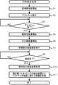
- the control unit 80 of the ophthalmic apparatus 1 executes the simultaneous examination process shown in FIG. 2 according to the program stored in the storage device 81.
- the control unit 80 starts projection of the fixation target by the fixation target projection optical system 50 (S1).
- the eye E to be inspected sees the projected fixation target.
- the alignment (alignment) of the ophthalmologic device 1 with respect to the eye E to be inspected is executed (S2).
- the control unit 80 detects the alignment state of the ophthalmic apparatus 1 with respect to the eye E to be inspected based on the position of the alignment index image in the anterior eye portion image captured by the two-dimensional photographing element 73.
- the ophthalmic appliance 1 of the present embodiment includes a driving unit (not shown) that moves the position of the apparatus with respect to the eye E to be inspected.
- the control unit 80 automatically executes the alignment by controlling the drive unit according to the detection result of the alignment state by the front eye portion image. However, the alignment may be performed by the user moving the device while looking at the anterior eye portion image displayed on the monitor 7.
- the control unit 80 starts the eye characteristic inspection by the eye characteristic inspection unit 10 (S5).
- the measurement index is projected on the fundus of the eye E to be inspected, and the ring-shaped fundus reflection image is photographed by the two-dimensional photographing element 22.
- the control unit 80 starts the inspection of the water content by the water content inspection unit 30 (S6).
- the water content measurement light is applied to the eyeball surface of the eye E to be inspected, and the reflected light (specifically, diffuse reflected light) of the water content measurement light from the eyeball surface is received.
- the water content test is continuously performed for a certain period of time.
- the control unit 80 executes a moving image of the anterior eye portion of the eye E to be inspected by the observation optical system 70 (S7).
- the control unit 80 acquires the measurement result of the refractive power of the eye to be inspected based on the fundus reflection image taken by the two-dimensional photographing element 22 (S10). Further, the control unit 80 detects the timing when the eye E to be inspected opens the eye (the timing when the eye is opened from the closed state) during the water content test. The control unit 80 acquires information on the degree of dry eye of the eye E to be inspected based on the elapsed time after the eye to be inspected E opens the eye and the information on the amount of water acquired by the water content inspection unit 30 ( S11).
- the control unit 80 detects the timing at which the eye to be inspected opens the eye by performing known image processing on the moving image of the anterior eye portion of the eye to be inspected E taken by the observation optical system 70. ..
- the control unit 80 detects the timing when the water content measured by the water content inspection unit 30 suddenly changes (for example, the timing when the water content suddenly increases) as the timing when the eye E to be inspected opens the eye. You may.
- the technology disclosed in the above embodiment is only an example. Therefore, it is possible to change the technique exemplified in the above embodiment. For example, only some of the plurality of techniques exemplified in the above embodiments may be adopted in the ophthalmic apparatus. Further, in the above embodiment, a photodiode is used as the receiver 5 for measuring moisture content. However, the two-dimensional photographing element may be used as a light receiver for moisture.
Landscapes
- Physics & Mathematics (AREA)
- Health & Medical Sciences (AREA)
- Life Sciences & Earth Sciences (AREA)
- Spectroscopy & Molecular Physics (AREA)
- General Health & Medical Sciences (AREA)
- Engineering & Computer Science (AREA)
- Veterinary Medicine (AREA)
- Heart & Thoracic Surgery (AREA)
- Medical Informatics (AREA)
- Molecular Biology (AREA)
- Surgery (AREA)
- Animal Behavior & Ethology (AREA)
- Ophthalmology & Optometry (AREA)
- Public Health (AREA)
- Biomedical Technology (AREA)
- Biophysics (AREA)
- Chemical & Material Sciences (AREA)
- Analytical Chemistry (AREA)
- Biochemistry (AREA)
- General Physics & Mathematics (AREA)
- Immunology (AREA)
- Pathology (AREA)
- Eye Examination Apparatus (AREA)
Priority Applications (1)
| Application Number | Priority Date | Filing Date | Title |
|---|---|---|---|
| JP2022541415A JP7513099B2 (ja) | 2020-08-07 | 2021-07-16 | 眼科装置 |
Applications Claiming Priority (2)
| Application Number | Priority Date | Filing Date | Title |
|---|---|---|---|
| JP2020-135322 | 2020-08-07 | ||
| JP2020135322 | 2020-08-07 |
Publications (1)
| Publication Number | Publication Date |
|---|---|
| WO2022030222A1 true WO2022030222A1 (ja) | 2022-02-10 |
Family
ID=80117267
Family Applications (1)
| Application Number | Title | Priority Date | Filing Date |
|---|---|---|---|
| PCT/JP2021/026780 Ceased WO2022030222A1 (ja) | 2020-08-07 | 2021-07-16 | 眼科装置 |
Country Status (2)
| Country | Link |
|---|---|
| JP (1) | JP7513099B2 (https=) |
| WO (1) | WO2022030222A1 (https=) |
Cited By (1)
| Publication number | Priority date | Publication date | Assignee | Title |
|---|---|---|---|---|
| WO2025205483A1 (ja) * | 2024-03-27 | 2025-10-02 | 株式会社Qdレーザ | 検査装置及び検査方法 |
Citations (4)
| Publication number | Priority date | Publication date | Assignee | Title |
|---|---|---|---|---|
| JP2015085042A (ja) * | 2013-10-31 | 2015-05-07 | 株式会社ニデック | 非接触式超音波眼圧計 |
| JP2015177403A (ja) * | 2014-03-17 | 2015-10-05 | セイコーエプソン株式会社 | 頭部装着型表示装置および頭部装着型表示装置の制御方法 |
| JP2016049255A (ja) * | 2014-08-29 | 2016-04-11 | 株式会社ニデック | 検眼装置 |
| WO2019027018A1 (ja) * | 2017-08-04 | 2019-02-07 | エルライズ株式会社 | 眼科測定装置、及び眼科測定システム |
Family Cites Families (1)
| Publication number | Priority date | Publication date | Assignee | Title |
|---|---|---|---|---|
| JP6286919B2 (ja) | 2013-08-08 | 2018-03-07 | カシオ計算機株式会社 | 画像処理装置、画像処理方法及びプログラム |
-
2021
- 2021-07-16 JP JP2022541415A patent/JP7513099B2/ja active Active
- 2021-07-16 WO PCT/JP2021/026780 patent/WO2022030222A1/ja not_active Ceased
Patent Citations (4)
| Publication number | Priority date | Publication date | Assignee | Title |
|---|---|---|---|---|
| JP2015085042A (ja) * | 2013-10-31 | 2015-05-07 | 株式会社ニデック | 非接触式超音波眼圧計 |
| JP2015177403A (ja) * | 2014-03-17 | 2015-10-05 | セイコーエプソン株式会社 | 頭部装着型表示装置および頭部装着型表示装置の制御方法 |
| JP2016049255A (ja) * | 2014-08-29 | 2016-04-11 | 株式会社ニデック | 検眼装置 |
| WO2019027018A1 (ja) * | 2017-08-04 | 2019-02-07 | エルライズ株式会社 | 眼科測定装置、及び眼科測定システム |
Cited By (1)
| Publication number | Priority date | Publication date | Assignee | Title |
|---|---|---|---|---|
| WO2025205483A1 (ja) * | 2024-03-27 | 2025-10-02 | 株式会社Qdレーザ | 検査装置及び検査方法 |
Also Published As
| Publication number | Publication date |
|---|---|
| JP7513099B2 (ja) | 2024-07-09 |
| JPWO2022030222A1 (https=) | 2022-02-10 |
Similar Documents
| Publication | Publication Date | Title |
|---|---|---|
| US11659992B2 (en) | Ophthalmic apparatus | |
| JP6685144B2 (ja) | 眼科装置及び眼科検査システム | |
| JP2022040372A (ja) | 眼科装置 | |
| JP7186587B2 (ja) | 眼科装置 | |
| WO2017135016A1 (ja) | 眼科装置及び眼科検査システム | |
| US11291368B2 (en) | Ophthalmologic apparatus and method of controlling the same | |
| JP6603545B2 (ja) | 眼科装置 | |
| CN110811536A (zh) | 眼科装置及其控制方法 | |
| CN106963336A (zh) | 眼科装置 | |
| JP2022164860A (ja) | 眼科装置 | |
| JP6898712B2 (ja) | 眼科装置 | |
| JP2023080218A (ja) | 眼科装置 | |
| JP7181135B2 (ja) | 眼科装置 | |
| JP7420476B2 (ja) | 眼科装置、その制御方法、眼科情報処理装置、その制御方法、プログラム、及び記録媒体 | |
| JP7727133B2 (ja) | 眼科装置 | |
| JP7513099B2 (ja) | 眼科装置 | |
| CN111557637B (zh) | 眼科测量系统 | |
| US20190282093A1 (en) | Ophthalmologic apparatus and method of controlling the same | |
| JP2020130266A (ja) | 眼科装置 | |
| JP6453096B2 (ja) | 眼科装置 | |
| JP7250626B2 (ja) | 眼科装置及び眼科装置の制御方法 | |
| JP6837107B2 (ja) | 眼科装置 | |
| JP7339011B2 (ja) | 眼科装置、眼科情報処理装置、プログラム、及び記録媒体 | |
| WO2026014145A1 (ja) | 眼科装置 | |
| JP6735963B2 (ja) | 眼科装置 |
Legal Events
| Date | Code | Title | Description |
|---|---|---|---|
| 121 | Ep: the epo has been informed by wipo that ep was designated in this application |
Ref document number: 21854205 Country of ref document: EP Kind code of ref document: A1 |
|
| ENP | Entry into the national phase |
Ref document number: 2022541415 Country of ref document: JP Kind code of ref document: A |
|
| NENP | Non-entry into the national phase |
Ref country code: DE |
|
| 122 | Ep: pct application non-entry in european phase |
Ref document number: 21854205 Country of ref document: EP Kind code of ref document: A1 |