WO2022026352A1 - Serpentine optical phased array with dispersion matched waveguides - Google Patents
Serpentine optical phased array with dispersion matched waveguides Download PDFInfo
- Publication number
- WO2022026352A1 WO2022026352A1 PCT/US2021/043113 US2021043113W WO2022026352A1 WO 2022026352 A1 WO2022026352 A1 WO 2022026352A1 US 2021043113 W US2021043113 W US 2021043113W WO 2022026352 A1 WO2022026352 A1 WO 2022026352A1
- Authority
- WO
- WIPO (PCT)
- Prior art keywords
- waveguides
- waveguide
- sections
- phased array
- dispersion
- Prior art date
- Legal status (The legal status is an assumption and is not a legal conclusion. Google has not performed a legal analysis and makes no representation as to the accuracy of the status listed.)
- Ceased
Links
Classifications
-
- G—PHYSICS
- G02—OPTICS
- G02F—OPTICAL DEVICES OR ARRANGEMENTS FOR THE CONTROL OF LIGHT BY MODIFICATION OF THE OPTICAL PROPERTIES OF THE MEDIA OF THE ELEMENTS INVOLVED THEREIN; NON-LINEAR OPTICS; FREQUENCY-CHANGING OF LIGHT; OPTICAL LOGIC ELEMENTS; OPTICAL ANALOGUE/DIGITAL CONVERTERS
- G02F1/00—Devices or arrangements for the control of the intensity, colour, phase, polarisation or direction of light arriving from an independent light source, e.g. switching, gating or modulating; Non-linear optics
- G02F1/29—Devices or arrangements for the control of the intensity, colour, phase, polarisation or direction of light arriving from an independent light source, e.g. switching, gating or modulating; Non-linear optics for the control of the position or the direction of light beams, i.e. deflection
- G02F1/292—Devices or arrangements for the control of the intensity, colour, phase, polarisation or direction of light arriving from an independent light source, e.g. switching, gating or modulating; Non-linear optics for the control of the position or the direction of light beams, i.e. deflection by controlled diffraction or phased-array beam steering
-
- G—PHYSICS
- G02—OPTICS
- G02B—OPTICAL ELEMENTS, SYSTEMS OR APPARATUS
- G02B6/00—Light guides; Structural details of arrangements comprising light guides and other optical elements, e.g. couplings
- G02B6/10—Light guides; Structural details of arrangements comprising light guides and other optical elements, e.g. couplings of the optical waveguide type
- G02B6/12—Light guides; Structural details of arrangements comprising light guides and other optical elements, e.g. couplings of the optical waveguide type of the integrated circuit kind
- G02B6/12007—Light guides; Structural details of arrangements comprising light guides and other optical elements, e.g. couplings of the optical waveguide type of the integrated circuit kind forming wavelength selective elements, e.g. multiplexer, demultiplexer
- G02B6/12009—Light guides; Structural details of arrangements comprising light guides and other optical elements, e.g. couplings of the optical waveguide type of the integrated circuit kind forming wavelength selective elements, e.g. multiplexer, demultiplexer comprising arrayed waveguide grating [AWG] devices, i.e. with a phased array of waveguides
- G02B6/12016—Light guides; Structural details of arrangements comprising light guides and other optical elements, e.g. couplings of the optical waveguide type of the integrated circuit kind forming wavelength selective elements, e.g. multiplexer, demultiplexer comprising arrayed waveguide grating [AWG] devices, i.e. with a phased array of waveguides characterised by the input or output waveguides, e.g. tapered waveguide ends, coupled together pairs of output waveguides
-
- G—PHYSICS
- G01—MEASURING; TESTING
- G01S—RADIO DIRECTION-FINDING; RADIO NAVIGATION; DETERMINING DISTANCE OR VELOCITY BY USE OF RADIO WAVES; LOCATING OR PRESENCE-DETECTING BY USE OF THE REFLECTION OR RERADIATION OF RADIO WAVES; ANALOGOUS ARRANGEMENTS USING OTHER WAVES
- G01S7/00—Details of systems according to groups G01S13/00, G01S15/00, G01S17/00
- G01S7/48—Details of systems according to groups G01S13/00, G01S15/00, G01S17/00 of systems according to group G01S17/00
- G01S7/481—Constructional features, e.g. arrangements of optical elements
- G01S7/4817—Constructional features, e.g. arrangements of optical elements relating to scanning
-
- G—PHYSICS
- G02—OPTICS
- G02B—OPTICAL ELEMENTS, SYSTEMS OR APPARATUS
- G02B6/00—Light guides; Structural details of arrangements comprising light guides and other optical elements, e.g. couplings
- G02B6/10—Light guides; Structural details of arrangements comprising light guides and other optical elements, e.g. couplings of the optical waveguide type
- G02B6/12—Light guides; Structural details of arrangements comprising light guides and other optical elements, e.g. couplings of the optical waveguide type of the integrated circuit kind
- G02B2006/12083—Constructional arrangements
- G02B2006/12107—Grating
-
- G—PHYSICS
- G02—OPTICS
- G02B—OPTICAL ELEMENTS, SYSTEMS OR APPARATUS
- G02B6/00—Light guides; Structural details of arrangements comprising light guides and other optical elements, e.g. couplings
- G02B6/10—Light guides; Structural details of arrangements comprising light guides and other optical elements, e.g. couplings of the optical waveguide type
- G02B6/12—Light guides; Structural details of arrangements comprising light guides and other optical elements, e.g. couplings of the optical waveguide type of the integrated circuit kind
- G02B6/12007—Light guides; Structural details of arrangements comprising light guides and other optical elements, e.g. couplings of the optical waveguide type of the integrated circuit kind forming wavelength selective elements, e.g. multiplexer, demultiplexer
- G02B6/12009—Light guides; Structural details of arrangements comprising light guides and other optical elements, e.g. couplings of the optical waveguide type of the integrated circuit kind forming wavelength selective elements, e.g. multiplexer, demultiplexer comprising arrayed waveguide grating [AWG] devices, i.e. with a phased array of waveguides
- G02B6/12011—Light guides; Structural details of arrangements comprising light guides and other optical elements, e.g. couplings of the optical waveguide type of the integrated circuit kind forming wavelength selective elements, e.g. multiplexer, demultiplexer comprising arrayed waveguide grating [AWG] devices, i.e. with a phased array of waveguides characterised by the arrayed waveguides, e.g. comprising a filled groove in the array section
Definitions
- the present invention relates generally to optical phased arrays. More specifically, it relates to solid state beam-steering using optical phased arrays.
- Optical beam-steering is a key feature of optical techniques such as light detection and ranging (LIDAR), projectors, and microscopy.
- LIDAR light detection and ranging
- these systems have used movable mirrors to steer beams.
- moving components are typically bulky, vibration-sensitive, and expensive.
- OPA optical phased array
- OPAs make use of a grid of optical antennas that emit light with a specific phase relation so that the antennas produce a directed beam. By altering the phase relations, the beam direction can be altered, i.e., steered.
- Fig. 1A is a schematic diagram of a simple four-element ID optical phased array.
- a laser 100 produces light that is split into four waveguides 102, 104, 106, 108.
- the four waveguides have four corresponding phase-shifting elements or tuners 110, 112, 114, 116 that induce a relative phase difference of D0 between the light in adjacent waveguides.
- the optical signals in the waveguides are then transmitted from four optical emitters 118, 120, 122, 124 and coherently combine to produce a beam 126 in a direction that depends on the phase difference D0 .
- the beam can be steered over a range of angles.
- One approach to solving this problem is to use wavelength-based steering instead of phase- shifting elements.
- changes in wavelength can be used to steer the beam in the longitudinal direction (i.e., in the direction of the waveguide), thereby eliminating the need for bulky phase shifters in the waveguide.
- this solves the problem for ID OPAs, the problem remains for 2D OPAs, because phase shifters or delay lines are still needed to control the phase of light entering each waveguide in order to control steering in the transverse direction.
- a 2D dispersion engineered 2D OPA is described in US20200379315, which is incorporated herein by reference.
- Multiple ID waveguides are arranged parallel to each other, where each waveguide 140 is a ID phased array with wavelength-based steering in the longitudinal direction, as shown in Fig. ID.
- the ID phased array lines are fed using splitter tree followed by phase shifting modulators 142 positioned at the start of each waveguide.
- the phase relation between the different waveguides results in steering of the beam in the transverse direction, defined by the angle Q, while the phase relation between emitters within each waveguide steers in the longitudinal direction, defined by the angle Y.
- the phase modulators limit the minimum spacing between the waveguides, and thus limit the transverse steering capabilities.
- FIG. IE Another 2D OPA architecture that uses wavelength based 2D steering is shown in Fig. IE. It is composed of a collection of ID OPAs 150, each using wavelength-based steering. The incoming light is split by a star coupler 152 that couples to a series of progressively longer waveguides 152, i.e., an arrayed waveguide grating. Relative phase differences between the signals fed into the ID OPAs results from the difference in length (hence phase delay) of the waveguides 152.
- This design however, has the disadvantage that the waveguides 154 take up considerable space.
- the total length of the delay elements scales with 0.5-L-(iV-l) 2 , where N is the number of waveguides, and L is the delay length. This is made worse for smaller bandwidth, because L will increase; and to decrease the antenna spacing, N will increase. This results in very large arrayed waveguide grating 154, much larger than the actual array
- a serpentine 2D OPA architecture avoids the arrayed waveguide grating space problem by routing the output 160 of each ID OPA 166 to the input 162 of the adjacent ID OPA via a waveguide 164 that passes between the two adjacent ID OPAs.
- the phase delay between neighboring waveguides results from the optical signal traveling through a ID OPA and the return waveguide before entering the next ID OPA.
- the key to this serpentine 2D OPA concept is to steer with wavelength in both dimensions by using grating couplers in one dimension and a sequential folded serpentine delay line in the other. This allows the frequency of a single tunable laser to implement wavelength-based beam steering in both longitudinal and transverse directions, eliminating the need for phase- shifters entirely. This makes the delay footprint considerably smaller.
- the returning waveguide 164 passing between adjacent waveguides limits the minimum spacing between the ID OPAs.
- Embodiments of the present invention provide a wavelength based steering 2D OPA architecture, which can steer light in both longitudinal and transverse directions, providing reduced footprint, improved antenna density, and small operating bandwidth.
- 2D OPA embodiments of the present invention combine ID OPAs in a serpentine arrangement, without interposed non-radiating return waveguides, to make a dense 2D OPA.
- the optical phased array uses slow light waveguides for slow wavelength-based steering in the longitudinal direction, and a serpentine architecture for fast steering in the transverse direction.
- the design uses two types of slow light waveguides having the same group index but opposite dispersion slopes. Unlike previous serpentine OPA architectures, where there is a non-radiating returning waveguide, this design uses a matched waveguide, so that light propagating in both directions radiates.
- the invention provides a dispersion-engineered 2D optical phased array device comprising: optical slow light waveguides arranged parallel to each other; waveguide bends optically coupling ends of adjacent waveguides of the optical slow light waveguides to form a serpentine optical configuration; wherein the optical slow light waveguides comprise first waveguides of a first waveguide type and second waveguides of a second waveguide type, wherein the first waveguides and the second waveguides are arranged adjacent to each other and alternate with each other; wherein the optical slow light waveguides comprise phased array sections, wherein first waveguides and second waveguides have dispersion slopes of opposite sign and the same group index; wherein the optical slow light waveguides comprise slow light delay waveguide sections that provide a delay between adjacent waveguides.
- the first waveguides of the first waveguide type comprise the slow light delay waveguide sections, and the second waveguides of the second waveguide type comprise middle phased array waveguide sections that couple directly to waveguide bends.
- the second waveguides of the second waveguide type comprise the slow light delay waveguide sections, and the first waveguides of the first waveguide type comprise middle phased array waveguide sections that couple directly to waveguide bends.
- the first waveguides of the first waveguide type and the second waveguides of the second waveguide type comprise the slow light delay waveguide sections.
- the slow light delay waveguide sections and the first phase array sections have equal dispersion slopes. In some embodiments, the slow light delay waveguide sections and the second phase array sections have equal dispersion slopes. In some embodiments, slow light delay waveguide sections of the first waveguides have dispersion slopes equal to dispersion slopes of the first phase array sections. In some embodiments, slow light delay waveguide sections of the second waveguides have dispersion slopes equal to dispersion slopes of the second phase array sections. In some embodiments, slow light delay waveguide sections provide equal phase delays between phased array sections of adjacent phased array sections.
- Fig. 1A is a schematic diagram of a simple four-element ID optical phased array using conventional phase shifting elements for each row.
- Fig. IB and Fig. 1C illustrate beam lobe patterns generated by ID optical phased arrays having different antenna spacing.
- Fig. ID shows a 2D dispersion engineered OPA made of multiple ID phased arrays each with a conventional phase shifting modulator, where wavelength-based steering is used in the longitudinal direction.
- Fig. IE shows a 2D OPA architecture that uses wavelength based 2D steering, where a star coupler and progressively longer waveguides are used to implement delays between the rows of the array.
- Fig. IF shows a serpentine 2D OPA architecture that uses non-radiating waveguides between radiating waveguides to implement delays between the rows of the array.
- Fig. 2 shows a schematic of an OPA device with a serpentine architecture and waveguides radiating from all waveguides, according to one embodiment of the invention.
- Fig. 3A shows a schematic side view of a dispersion engineered waveguide, according to one embodiment of the invention.
- Fig. 3B is a graph showing the relation between the frequency and a waveguide’s wavevector, i.e., the dispersion relation, according to one embodiment of the invention.
- Fig. 4 is a close up of a graph showing the dispersion relation of waveguides of a first type and waveguides of a second type, according to one embodiment of the invention.
- Fig. 5 illustrates a zig-zag raster scanning pattern generated by an OPA used to steer slowly in the longitudinal axis and very fast in the transverse direction, according to one embodiment of the invention.
- Figs. 6A-B show two alternative embodiments based on the same principles of Fig. 2, illustrating alternatives for realizing slow light delays between phased array sections of waveguides of an OPA, according to embodiments of the invention.
- Fig. 7 shows a dispersion-engineered design of a serpentine 2D OPA, according to one embodiment of the invention.
- Embodiments of the invention provide an OPA architecture that steers in two directions by sweeping the wavelength, without any phase-shifting elements.
- the architecture can work in a small bandwidth and has a high antenna density, assuring a large sweep angle.
- the architecture has a serpentine structure based on two distinct types of group-index matched slow light waveguides.
- Slow light waveguides accommodate slow wavelength-based steering in the longitudinal direction, i.e., the direction along the waveguide.
- a serpentine architecture is used.
- the design includes two distinct types of slow light waveguides, which have the same group index but an opposite dispersion slope.
- the present design uses a matched waveguide, which radiates as well. By eliminating the non-radiating returning waveguide, the design achieves higher antenna density and, as a result, a larger 2D scanning cone.
- FIG. 2 A schematic of an OPA device according to one embodiment of the invention is shown in Fig. 2.
- the OPA device is composed of a collection of dispersion-engineered slow light waveguides, joined by waveguide bends to form a serpentine structure.
- Light 200 enters the OPA by coupling into the left end of a first long slow light waveguide 202.
- a series of optical antenna structures 204 are positioned in a middle phased array section of the waveguide 202.
- a slow light waveguide is waveguide with an optical mode that has a low group velocity, v g .
- the group velocity is determined by the slope in the dispersion relation, ⁇ w/dk.
- people use the comparison with the speed of light as a measure, c/v g , this is called the group index.
- a normal silicon waveguide has a group index of 3-5.
- a slow light waveguide has an index greater than 8.
- the waveguides in embodiments of the present invention preferably have a group index of 20-25.
- the right end of the first waveguide 202 couples to a waveguide bend 206 that couples to the right end a second waveguide 208 positioned parallel to and adjacent to the first waveguide.
- the second waveguide 208 has the same group index as the first waveguide 202 but an opposite dispersion slope as the first waveguide.
- the right sections of the first and second waveguides, together with the waveguide bend 206 form a slow light delay 210 between middle sections of the first and second waveguides.
- a series of antenna structures 212 are positioned in the middle section of the second waveguide 208.
- middle sections which contain optical antenna structures, form the first two rows of a slow light phased array 214.
- another waveguide bend 216 couples to a third waveguide 218 positioned parallel to and adjacent to the second waveguide.
- the left sections of the second and third waveguides, together with the waveguide bend 216 form a slow light delay between the second and third rows of antennas in the slow light phased array 214.
- the first and third waveguides 202 and 218 are of the same type, i.e., have the same group index and the same dispersion slope.
- the second waveguide 208 is a different type, i.e., has the same group index as the first and third waveguides, but the opposite dispersion slope as the first and third waveguides.
- the OPA device is composed of waveguides that have the same group index but alternate in their dispersion slopes, so that adjacent waveguides have the same group index but alternate dispersion slopes.
- the light propagates through adjacent waveguides in opposite directions, and light is emitted by antenna structures as it propagates in both directions.
- the rows of the slow light phased array can be positioned adjacent to each other, without any nonradiating return waveguide separating them.
- FIG. 3A shows a schematic side view of such a waveguide 300.
- Light travels from left to right, as indicated by the waveguide’s wavevector, b.
- wavevector wavevector
- the direction of this wavefront, indicated by the wavevector relates to the waveguide’s wavevector and the antenna spacing by the grating relation: where n is an integer.
- the relation between the frequency and the waveguide’s wavevector, i.e., the dispersion relation is depicted in Fig. 3B.
- the waveguide mode’s dispersion curve 310 is very flat, which is characteristic for a slow light mode. Small changes in w result in large changes in the wavenumber b. This causes the angle Q to shift with the changing frequency w.
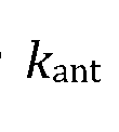
- the OPA architecture advantageously is composed of a series of waveguides of two alternating types, even numbered waveguides and odd numbered waveguides. These two different waveguide types are designed such that they provide the same wavelength-based steering behavior even though light passes through them in opposite directions. This is accomplished using different dispersion relations for the two different types of waveguides. Specifically, both waveguide types are slow-light waveguide with the same group index, but with oppositely signed dispersion slopes, i.e., where the graph of the dispersion relation of one is substantially equal to the mirror image of that of the other. Taking into account the change in the magnitude of /f air results in a small deviation of the mirror image being an exact mirror image. Deviations in the dispersion will result in phase errors.
- Fig. 4 shows a close up of a graph showing the dispersion relation of the waveguides of the first type 400 and waveguides of the second type 402. The opposing slope will cause the direction of the radiation emitted from the forward and back waveguides to move at the same pace.
- the main radiation lobe also needs to line up. This can be accomplished by carefully choosing the antenna periodicity in the waveguides.
- n and m are integers.
- Transverse steering ( ip ) of the beam from the OPA is accomplished by designing the OPA to have a phase delay (e.g., 210, Fig. 2) between the central phased array sections of adjacent waveguides. This phase delay can be increased by making the slow-light delay sections (e.g., 210) longer.
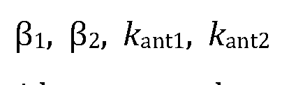
- the angle in the transverse direction can be derived by the accumulated phase caused by passing through the delay element: where g is the spacing between the waveguides, n is an integer, / delay is the length of the delay line, and is the added phase of the bend element. From Equation 2, we can see that by having a large delay section, the scanning speed as a function of frequency can be increased. Therefore, the beam can be steered very fast in the transverse direction.
- the OPA may be used to steer slowly in the longitudinal axis and very fast in the transverse direction, resulting in a zig-zag raster scanning pattern, as shown in Fig. 5, where horizontal axis shows the beam scanning angle in the fast, transverse direction, and the vertical axis shows the beam scanning angle in the slow, longitudinal direction.
- Figs. 6A-B show two alternative embodiments based on the same principles shown in the embodiment of Fig. 2.
- the common features of these embodiments is that the middle slow light phased array sections of the waveguides have opposite dispersion slopes, while the phase delay sections on the right and left of the phased array sections do not necessarily share this feature. It suffices that they provide phase delays, and opposite dispersion slopes are not necessary for these right and left sections.
- Fig. 6A shows and embodiment that is identical to that of Fig. 2 except that the second waveguide type 600 (i.e., even numbered waveguides) has only a middle phased array waveguide section, which couples directly to the waveguide bends 602, 604 without any slow light delay sections to the right or left of the middle phased array section.
- the first waveguide type 606 (i.e., odd numbered waveguides) is identical to that of Fig. 2 and has slow light delay sections to the right and left of the phased array section to provide delay between rows of the slow light phased array.
- Another alternative embodiment would be to provide a slow light delay section to the right of the middle slow light phased array section of the second waveguide type, but not to the left, or vice versa; or to have a partial slow light delay section to the right or to the left, or both.
- Yet another embodiment would be like that of Fig. 6A except that the first waveguide type has some or all of its slow light delay sections replaced by waveguide bends instead of the second waveguide type.
- both waveguide types could have some or all of their slow light delay sections replaced by waveguide bends, provided there is at least some waveguide delay section between adjacent phased array section, and that the delay is the same between all phased arrays sections of the OPA.
- the slow light delay waveguide sections 610 in the waveguides of first and second types could have the same dispersion slopes. It suffices that the first and second waveguide types have opposite dispersion slopes in the slow light phased array sections. More generally, the dispersion slopes of the slow light delay sections need not have opposite dispersion slopes. In summary, it suffices to have slow light delay waveguide sections between adjacent phased array sections of the OPA, where the delay between any two adjacent phased array waveguides in the OPA is the same.
- Fig. 7 shows a dispersion-engineered design of a serpentine 2D OPA with six waveguides including six phased array sections 700, 702, 704, 706, 708, 710.
- the phased array sections are coupled on both ends to sets of waveguide delays 712 and 714.
- Waveguides, each including a phased array section and two delays, are connected by sets of waveguide bends 716 and 718.
- This small OPA is shown for purposes of illustration. For typical commercial applications the OPA would be larger, i.e., have longer waveguides and a larger number of waveguides.
- the first and second waveguide types have different dispersion- engineered structures to implement their opposite dispersion slopes. Techniques of inverse design can be used to design such dispersion engineered waveguides with positive and negative slope.
- the structure could be made starting from an SOI wafer.
- the structure would be patterned by lithographically, i.e., e-beam lithography in lab situation or optical lithography in industrial. After etching silicon the device could be undercut by a box etch or covered with oxide, to create a homogeneous optical environment around the structure.
- the structure in the presentation was made assuming we would have an undercut structure.
- the device could be used in a LIDAR application to scan a light beam in 2D by only changing the laser wavelength.
- Another application would be for free space communication. By varying the wavelength one can scan the beam and target a receiver. With knowledge of the wavelength that points the beam to the receiving device one can modulate the laser and send data.
Landscapes
- Physics & Mathematics (AREA)
- General Physics & Mathematics (AREA)
- Optics & Photonics (AREA)
- Nonlinear Science (AREA)
- Engineering & Computer Science (AREA)
- Microelectronics & Electronic Packaging (AREA)
- Computer Networks & Wireless Communication (AREA)
- Radar, Positioning & Navigation (AREA)
- Remote Sensing (AREA)
- Variable-Direction Aerials And Aerial Arrays (AREA)
- Optical Integrated Circuits (AREA)
- Optical Modulation, Optical Deflection, Nonlinear Optics, Optical Demodulation, Optical Logic Elements (AREA)
Abstract
Description





Claims
Priority Applications (3)
| Application Number | Priority Date | Filing Date | Title |
|---|---|---|---|
| JP2023505703A JP2023536084A (en) | 2020-07-30 | 2021-07-26 | Serpentine Optical Phased Array Using Dispersion-matched Waveguides |
| US18/015,930 US12019268B2 (en) | 2020-07-30 | 2021-07-26 | Serpentine optical phased array with dispersion matched waveguides |
| KR1020237006636A KR20230047134A (en) | 2020-07-30 | 2021-07-26 | Tortuous Optical Phased Array with Dispersive Matched Waveguides |
Applications Claiming Priority (2)
| Application Number | Priority Date | Filing Date | Title |
|---|---|---|---|
| US202063058728P | 2020-07-30 | 2020-07-30 | |
| US63/058,728 | 2020-07-30 |
Publications (1)
| Publication Number | Publication Date |
|---|---|
| WO2022026352A1 true WO2022026352A1 (en) | 2022-02-03 |
Family
ID=80036977
Family Applications (1)
| Application Number | Title | Priority Date | Filing Date |
|---|---|---|---|
| PCT/US2021/043113 Ceased WO2022026352A1 (en) | 2020-07-30 | 2021-07-26 | Serpentine optical phased array with dispersion matched waveguides |
Country Status (4)
| Country | Link |
|---|---|
| US (1) | US12019268B2 (en) |
| JP (1) | JP2023536084A (en) |
| KR (1) | KR20230047134A (en) |
| WO (1) | WO2022026352A1 (en) |
Cited By (2)
| Publication number | Priority date | Publication date | Assignee | Title |
|---|---|---|---|---|
| WO2024213209A1 (en) * | 2023-04-13 | 2024-10-17 | Continental Autonomous Mobility Germany GmbH | Lidar system with radiative waveguide array or radiative waveguide surface and feed waveguide |
| WO2024213208A1 (en) * | 2023-04-13 | 2024-10-17 | Continental Autonomous Mobility Germany GmbH | Lidar system comprising radiative waveguide array or radiative waveguide surface and planar lens for parallel sensing |
Families Citing this family (11)
| Publication number | Priority date | Publication date | Assignee | Title |
|---|---|---|---|---|
| US12535586B2 (en) | 2018-08-31 | 2026-01-27 | SiLC Technology, Inc. | Reduction of ADC sampling rates in LIDAR systems |
| US12541009B2 (en) | 2021-06-17 | 2026-02-03 | Silc Technologies, Inc. | Scanning multiple LIDAR system output signals |
| US20220413100A1 (en) * | 2021-06-28 | 2022-12-29 | Seagate Technology Llc | Lidar photonic isolator |
| US20230069201A1 (en) * | 2021-09-02 | 2023-03-02 | Silc Technologies, Inc. | Use of multiple steering mechanisms in scanning |
| US12411213B2 (en) | 2021-10-11 | 2025-09-09 | Silc Technologies, Inc. | Separation of light signals in a LIDAR system |
| US12553995B2 (en) | 2022-02-14 | 2026-02-17 | Silc Technologies, Inc. | Data refinement in optical systems |
| US12578443B2 (en) | 2022-04-23 | 2026-03-17 | Silc Technologies, Inc. | Data refinement in optical imaging systems |
| US11894873B2 (en) * | 2022-06-29 | 2024-02-06 | Raytheon Company | Photonic integrated circuit with inverted H-tree unit cell design |
| US12663516B2 (en) | 2022-07-08 | 2026-06-23 | Silc Technologies, Inc. | Imaging system with enhanced scan rate |
| US12422618B2 (en) | 2022-10-13 | 2025-09-23 | Silc Technologies, Inc. | Buried taper with reflecting surface |
| US12578439B2 (en) | 2023-04-11 | 2026-03-17 | Silc Technologies, Inc. | Increasing resolution in imaging systems |
Citations (5)
| Publication number | Priority date | Publication date | Assignee | Title |
|---|---|---|---|---|
| US5144690A (en) * | 1990-12-03 | 1992-09-01 | Corning Incorporated | Optical fiber sensor with localized sensing regions |
| US20030123794A1 (en) * | 2001-12-27 | 2003-07-03 | Chowdhury Dipakbin Qasem | Chromatic dispersion and dispersion slope control method and apparatus |
| US20120013962A1 (en) * | 2010-07-19 | 2012-01-19 | Omega Optics, Inc. | Two-dimensional surface normal slow-light photonic crystal waveguide optical phased array |
| US20130028552A1 (en) * | 2011-07-25 | 2013-01-31 | Harris Corporation, Corporation Of The State Of Delaware | Tunable rf filter device using optical waveguide paths with splitter and combiner pairs and related methods |
| US20200225332A1 (en) * | 2018-03-28 | 2020-07-16 | Kelvin Wagner | Self-Calibration Adaptive Lidar Aperture Building-block Light Engine |
-
2021
- 2021-07-26 US US18/015,930 patent/US12019268B2/en active Active
- 2021-07-26 JP JP2023505703A patent/JP2023536084A/en active Pending
- 2021-07-26 WO PCT/US2021/043113 patent/WO2022026352A1/en not_active Ceased
- 2021-07-26 KR KR1020237006636A patent/KR20230047134A/en not_active Withdrawn
Patent Citations (5)
| Publication number | Priority date | Publication date | Assignee | Title |
|---|---|---|---|---|
| US5144690A (en) * | 1990-12-03 | 1992-09-01 | Corning Incorporated | Optical fiber sensor with localized sensing regions |
| US20030123794A1 (en) * | 2001-12-27 | 2003-07-03 | Chowdhury Dipakbin Qasem | Chromatic dispersion and dispersion slope control method and apparatus |
| US20120013962A1 (en) * | 2010-07-19 | 2012-01-19 | Omega Optics, Inc. | Two-dimensional surface normal slow-light photonic crystal waveguide optical phased array |
| US20130028552A1 (en) * | 2011-07-25 | 2013-01-31 | Harris Corporation, Corporation Of The State Of Delaware | Tunable rf filter device using optical waveguide paths with splitter and combiner pairs and related methods |
| US20200225332A1 (en) * | 2018-03-28 | 2020-07-16 | Kelvin Wagner | Self-Calibration Adaptive Lidar Aperture Building-block Light Engine |
Cited By (2)
| Publication number | Priority date | Publication date | Assignee | Title |
|---|---|---|---|---|
| WO2024213209A1 (en) * | 2023-04-13 | 2024-10-17 | Continental Autonomous Mobility Germany GmbH | Lidar system with radiative waveguide array or radiative waveguide surface and feed waveguide |
| WO2024213208A1 (en) * | 2023-04-13 | 2024-10-17 | Continental Autonomous Mobility Germany GmbH | Lidar system comprising radiative waveguide array or radiative waveguide surface and planar lens for parallel sensing |
Also Published As
| Publication number | Publication date |
|---|---|
| KR20230047134A (en) | 2023-04-06 |
| JP2023536084A (en) | 2023-08-23 |
| US12019268B2 (en) | 2024-06-25 |
| US20230258861A1 (en) | 2023-08-17 |
Similar Documents
| Publication | Publication Date | Title |
|---|---|---|
| US12019268B2 (en) | Serpentine optical phased array with dispersion matched waveguides | |
| US10613410B2 (en) | Large scale optical phased array | |
| US11573294B2 (en) | Switched optical phased array based beam steering LiDAR | |
| JP7076822B2 (en) | Optical receiver array and rider device | |
| CN112673273B (en) | lidar device | |
| US11422431B2 (en) | Optical switching using spatially distributed phase shifters | |
| JP5692865B2 (en) | Wavelength cross-connect equipment | |
| US11194223B2 (en) | Densely-packed optical phased arrays via k-vector mismatch and metamaterial rods | |
| JP4960294B2 (en) | Wavelength selective switch | |
| CN113985603B (en) | Light beam scanning system | |
| US20020186919A1 (en) | Electro-optical programmable true-time delay generator | |
| CN113608305B (en) | Beam controller and beam control method | |
| EP4363928A1 (en) | Integrated optical phased array | |
| CN112946929A (en) | One-dimensional optical phased array based on apodization modulation | |
| CN114384495A (en) | High-precision on-chip optical beam forming network | |
| CN115793144A (en) | Phase shifter structure for beam steering apparatus | |
| CN113534564A (en) | Method and device for improving scanning angle of optical phased array | |
| CN110221386A (en) | A kind of optical waveguide optical beam deflecting device and light beam deflection method | |
| CN114217293B (en) | Optical multi-beamforming network chip and network | |
| CN114280575B (en) | Laser radar optical chip based on micro-ring optical switch network | |
| KR101302260B1 (en) | Device for controlling light | |
| US20240345381A1 (en) | Managing optical beam steering | |
| JP2018124402A (en) | Optical input/output device | |
| CN117581154A (en) | Integrated optical phased array | |
| Ashtiani et al. | Optical Beam Steering Using an NxN Phased Array with 2N Phase Shifters |
Legal Events
| Date | Code | Title | Description |
|---|---|---|---|
| 121 | Ep: the epo has been informed by wipo that ep was designated in this application |
Ref document number: 21850421 Country of ref document: EP Kind code of ref document: A1 |
|
| ENP | Entry into the national phase |
Ref document number: 2023505703 Country of ref document: JP Kind code of ref document: A |
|
| ENP | Entry into the national phase |
Ref document number: 20237006636 Country of ref document: KR Kind code of ref document: A |
|
| NENP | Non-entry into the national phase |
Ref country code: DE |
|
| 122 | Ep: pct application non-entry in european phase |
Ref document number: 21850421 Country of ref document: EP Kind code of ref document: A1 |