WO2022025191A1 - 棚札取付装置 - Google Patents
棚札取付装置 Download PDFInfo
- Publication number
- WO2022025191A1 WO2022025191A1 PCT/JP2021/028120 JP2021028120W WO2022025191A1 WO 2022025191 A1 WO2022025191 A1 WO 2022025191A1 JP 2021028120 W JP2021028120 W JP 2021028120W WO 2022025191 A1 WO2022025191 A1 WO 2022025191A1
- Authority
- WO
- WIPO (PCT)
- Prior art keywords
- shelf
- holding
- shelf label
- shelf tag
- tag
- Prior art date
- Legal status (The legal status is an assumption and is not a legal conclusion. Google has not performed a legal analysis and makes no representation as to the accuracy of the status listed.)
- Ceased
Links
Images


Classifications
-
- A—HUMAN NECESSITIES
- A47—FURNITURE; DOMESTIC ARTICLES OR APPLIANCES; COFFEE MILLS; SPICE MILLS; SUCTION CLEANERS IN GENERAL
- A47F—SPECIAL FURNITURE, FITTINGS, OR ACCESSORIES FOR SHOPS, STOREHOUSES, BARS, RESTAURANTS OR THE LIKE; PAYING COUNTERS
- A47F5/00—Show stands, hangers, or shelves characterised by their constructional features
- A47F5/08—Show stands, hangers, or shelves characterised by their constructional features secured to the wall, ceiling, or the like; Wall-bracket display devices
- A47F5/0807—Display panels, grids or rods used for suspending merchandise or cards supporting articles; Movable brackets therefor
- A47F5/0869—Accessories for article-supporting brackets, e.g. price- indicating means, not covered by a single one of groups A47F5/08
-
- G—PHYSICS
- G09—EDUCATION; CRYPTOGRAPHY; DISPLAY; ADVERTISING; SEALS
- G09F—DISPLAYING; ADVERTISING; SIGNS; LABELS OR NAME-PLATES; SEALS
- G09F3/00—Labels, tag tickets, or similar identification or indication means; Seals; Postage or like stamps
- G09F3/08—Fastening or securing by means not forming part of the material of the label itself
- G09F3/18—Casings, frames or enclosures for labels
- G09F3/20—Casings, frames or enclosures for labels for adjustable, removable, or interchangeable labels
- G09F3/204—Casings, frames or enclosures for labels for adjustable, removable, or interchangeable labels specially adapted to be attached to a shelf or the like
-
- A—HUMAN NECESSITIES
- A47—FURNITURE; DOMESTIC ARTICLES OR APPLIANCES; COFFEE MILLS; SPICE MILLS; SUCTION CLEANERS IN GENERAL
- A47F—SPECIAL FURNITURE, FITTINGS, OR ACCESSORIES FOR SHOPS, STOREHOUSES, BARS, RESTAURANTS OR THE LIKE; PAYING COUNTERS
- A47F5/00—Show stands, hangers, or shelves characterised by their constructional features
- A47F5/0043—Show shelves
- A47F5/0068—Shelf extensions, e.g. fixed on price rail
-
- G—PHYSICS
- G09—EDUCATION; CRYPTOGRAPHY; DISPLAY; ADVERTISING; SEALS
- G09F—DISPLAYING; ADVERTISING; SIGNS; LABELS OR NAME-PLATES; SEALS
- G09F3/00—Labels, tag tickets, or similar identification or indication means; Seals; Postage or like stamps
- G09F3/08—Fastening or securing by means not forming part of the material of the label itself
- G09F3/18—Casings, frames or enclosures for labels
- G09F3/20—Casings, frames or enclosures for labels for adjustable, removable, or interchangeable labels
- G09F3/208—Electronic labels, Labels integrating electronic displays
Definitions
- the present invention relates to a shelf tag attaching device.
- an adapter for a double hook hanger described in Patent Document 1 (hereinafter referred to as "adapter") has been proposed.
- the adapter described in Patent Document 1 is an adapter attached to the tip of the upper bar member, and includes a price indicator, a tip engaging member, and an intermediate member.
- the price display tool includes a price display means support portion on the front surface and a rear engaging portion on the back surface.
- the tip engaging member has a pair of left and right engaging protrusions mounted on the tip of the upper bar member.
- the intermediate member has a first engaging portion that engages the rear engaging portion of the price indicator and a second engaging portion that engages a pair of engaging projections of the tip engaging member.
- the second engaging portion of the intermediate member consists of a pair of left and right upper arm portions and a pair of left and right lower arm portions having a mountain portion formed by two recesses on the inner peripheral portion.
- the pair of left and right engaging protrusions have a protruding portion extending diagonally forward and downward in the lower front portion of the short shaft member having a substantially circular cross section, and are sandwiched inside the upper arm portion and the lower arm portion.
- Patent Document 1 when the displayed product is pulled out, the product or a human hand hits the back surface of the price display, so that the price display has a pair of engaging protrusions of the tip engaging member.
- the display surface faces diagonally upward as the center.
- the price indicator rotates in the direction of returning to the original posture around the pair of engaging protrusions of the tip engaging member due to its own weight. Since this rotation is terminated by the contact between the back surface of the intermediate member and the front surface of the tip engaging member, Patent Document 1 describes that the display surface of the price display becomes vertical and returns to the original display posture. ..
- the present invention has been made in view of the above circumstances, and one of the purposes thereof is to set a predetermined range in a direction in which the display surface of the shelf label faces downward by a shelf label mounting device having a relatively simple structure. It is to prevent it from rotating beyond.
- the shelf tag attaching device is A shelf label holder for holding the first shelf label, A support member that rotatably supports the shelf label holding portion around a rotation axis extending in the lateral direction of the first shelf label is provided.
- the shelf tag holding portion has a first fitting portion that is one of a shaft portion and a bearing portion for rotating around the rotation axis with respect to the support member.
- the support member is provided with a second fitting portion that is the other side of the shaft portion and the bearing portion, and has an arm portion that sandwiches the first fitting portion from the lateral direction.
- the shelf label holding portion has a stopper that locks the display surface of the first shelf label so as not to rotate beyond a predetermined range in a downward direction by coming into contact with the arm portion.
- the shelf label mounting device having a relatively simple structure.
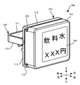
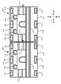
- FIG. 1 It is a rear view which shows the example which arranged the shelf tag holding part which concerns on one Embodiment at a narrow space so that they may make contact with each other in the left-right direction. It is a front view of the shelf tag holding part which concerns on modification 1. FIG. It is a front view of the shelf tag holding part which concerns on modification 2. FIG.
- the shelf tag attaching device 100 is a device for attaching an electronic shelf tag 101 for displaying a product price or the like to a product shelf. It includes an electronic shelf tag 101, a support member 102, and a shelf tag holding portion 103.
- the electronic shelf label 101 is a shelf label having a display unit 104 composed of, for example, a liquid crystal display panel on the display surface.
- the display unit 104 typically displays a product name, a price, an advertisement, and the like.
- the electronic shelf label 101 is an example of a first shelf label, and the first shelf label may be made of paper, paper held on a resin plate, resin, or the like.
- the display unit 104 when the display unit 104 (that is, the display surface) is arranged in parallel with the vertical direction, the display unit 104 is correctly oriented in the vertical direction such as characters and symbols displayed on the display unit 104.
- the direction in which is facing is the front, and the opposite direction is the rear. Further, the vertical direction in this case follows vertically above and vice versa.
- the left-right direction shall be defined when viewed from the front, and corresponds to the lateral direction. It should be noted that these directions are used for explaining the present invention, and are not intended to limit the present invention.
- the electronic shelf label 101 has a substantially rectangular parallelepiped shape and has a groove portion 105 extending laterally at the upper end.
- the upper end of the electronic shelf label 101 according to the present embodiment is planar, and the groove 105 is provided near the rear end of the upper end of the electronic shelf label 101.
- the groove portion 105 is composed of a front step portion 106, an upper surface portion 107 facing upward, and a rear wall portion 108 provided at a space between the rear ends of the upper surface portion 107.
- the groove portions 105 are provided discretely at intervals in the lateral direction. Therefore, the groove 105 has a portion that opens rearward.
- three rear wall portions 108 arranged in the lateral direction are provided, and a space is provided between the central rear wall portion 108 and the left and right rear wall portions 108, whereby the groove portion 105 is divided into two. It is open to the rear at several places.
- groove 105 (upper groove 105) provided at the upper end of the electronic shelf label 101 has been described with reference to FIG. 2, but the same groove 105 as the upper end is also provided at the lower end of the electronic shelf tag 101. Be done.
- the groove 105 (lower groove 105) provided at the lower end of the electronic shelf tag 101 is a rear wall portion provided at a space between the front step portion, the lower surface portion facing downward, and the rear end of the lower surface portion. It is composed of and. Also in the lower groove portion 105, three rear wall portions 108 arranged in the lateral direction are provided at intervals. As a result, the lower groove portion 105 is also provided discretely at intervals in the lateral direction, similarly to the upper groove portion 105.
- the position of the region to be opened rearward in the left-right direction is the same in the upper and lower groove portions 105.
- the support member 102 is a member that rotatably supports the shelf label holding portion 103 to which the electronic shelf label 101 is attached about a rotation axis P extending in the lateral direction of the electronic shelf label 101, and is an example in FIG. As shown, it is attached to the first product shelf MS1.
- the support member 102 is attached to the tip of a rod-shaped body 109 protruding forward from the first product shelf MS1.
- the support member 102 and the rod-shaped body 109 are made of resin, metal, or the like.
- the support member 102 and the rod-shaped body 109 may be individually formed of different materials or the same material, but may be integrally formed of the support member 102.
- the support member 102 has an arm portion 110 provided in pairs on the left and right, and a connecting fixing portion 111 for connecting the arm portions 110 and fixing them to the rod-shaped body 109.
- the left and right arm portions 110 are flat plate-shaped portions that are opposed to each other at intervals in the left-right direction, and are elongated in the front-rear direction. Each tip of the arm portion 110 is substantially semicircular when viewed from the lateral direction.
- Each of the left and right arm portions 110 has a shaft portion 112 as a second fitting portion extending inward near the tip of the inner surface.
- the inner surface is a surface facing inward.
- the inside is the right side of the left arm portion 110 and the left side of the right arm portion 110.
- the shaft portion 112 is provided through the center of a semicircle formed by the outer shape of the tip when viewed from the lateral direction.
- the connecting and fixing portion 111 is a flat plate-shaped portion parallel to the vertical direction and elongated in the horizontal direction, and the tip of the rod-shaped body 109 is fixed to a substantially center in the horizontal direction.
- the rear ends of the arm portion 110 are connected to the left and right ends of the connection fixing portion 111.
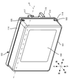
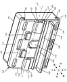
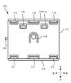
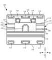
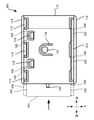
- the shelf tag holding portion 103 is a portion for holding the electronic shelf tag 101, and is made of, for example, resin. As shown in the front view, the rear view, the right side view, and the bottom view of FIGS. It has 115, a spring portion 116, left and right clip portions 117, left and right insertion portions 118, a holding plate portion 119, and a holding plate connecting portion 120.
- the shelf tag mounting portion 113 is a substantially rectangular flat plate-shaped portion having a thickness in the front-rear direction.
- the upper end and the lower end of the shelf tag mounting portion 113 extend in the left-right direction, and the left end and the right end extend in the up-down direction.
- the brim portion 114 protrudes forward from each of the upper end and the lower end of the shelf tag mounting portion 113, and is continuous in the lateral direction.
- the upper protrusion 115 protrudes downward, and the lower protrusion 115 protrudes upward. As a result, the upper protrusion 115 fits into the upper groove 105, and the lower protrusion 115 fits into the lower groove 105 to hold the electronic shelf label 101.
- the upper protrusion 115 projects downward from the upper brim 114, and is provided so as to be discretely arranged in the left-right direction. In the present embodiment, three are provided side by side with a space (gap) on the left and right.
- the lower protrusion 115 protrudes upward from the lower brim 114, and is provided so as to be discretely arranged in the left-right direction. In the present embodiment, three are provided side by side with an interval in the left-right direction.
- the protrusion 115 is provided near the front end of the brim 114, so that a groove is formed between the shelf tag mounting portion 113 and the protrusion 115. Since the upper protrusion 115 and the lower protrusion 115 are lined up at intervals in the left-right direction as described above, the groove between the shelf tag mounting portion 113 and the protrusion 115 is forward through the gap. Open.
- the distance provided in the upper protrusion 115 and the distance provided in the lower protrusion 115 are the same in the left-right direction. That is, the positions of the regions opened forward in the left-right direction are the same for the upper and lower grooves.
- the spring portion 116 is a cantilever-shaped portion provided substantially in the center of the shelf tag mounting portion 113 when viewed from the front, and has a pressing protrusion 121 protruding forward in the vicinity of the tip.
- the spring portion 116 presses the pressing protrusion 121 by the back surface of the electronic shelf tag 101, and pushes the electronic shelf tag 101 forward by elastic force.
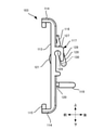
- the clip portion 117 is provided on the back surface of the shelf tag mounting portion 113, and forms a notch with an open lower portion for sandwiching the plate provided on the second product shelf MS2 as a shelf.
- the second product shelf MS2 is a shelf in which the method of attaching the electronic shelf tag 101 is different from that of the above-mentioned first product shelf MS.
- the second product shelf MS2 is generally arranged in a shelf 122 on which products are arranged, a partition plate 123 extending vertically and horizontally in front of the shelf 122, and in front of the partition plate 123 and below the shelf 122. It has an L-shaped plate 124.
- the L-shaped plate 124 is a plate-shaped member bent in an L-shape when viewed from the left-right direction.
- the L-shaped plate 124 has a front plate 125 arranged substantially parallel to the partition plate 123 in front of the partition plate 123 with a relatively narrow gap, and a fixing portion 126 fixed to the lower part of the shelf 122 by screwing or the like. And have.
- the clip portion 117 is a portion for sandwiching the front plate 125 inserted from below.
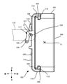
- each of the left and right clip portions 117 has an extending portion 127 extending rearward from the back surface of the shelf tag attaching portion 113, and a hanging portion 128 hanging downward from the rear end of the extending portion 127.
- a gap for sandwiching the front plate 125 is formed between the hanging portion 128 and the shelf tag mounting portion 113, and when the front plate 125 is sandwiched, the front plate 125 is placed.
- An elastic force for sandwiching and holding can be applied to the front plate 125.
- a bearing portion 129 as a first fitting portion into which the shaft portion 112 is fitted is provided at a portion where each of the left and right clip portions 117 is connected to the shelf tag mounting portion 113.
- the bearing portion 129 according to the present embodiment forms a columnar through hole extending to the left and right, and is provided in the extending portion 127, the hanging portion 128, and the shelf tag mounting portion 113.
- the lengths of the hanging portions 128 of the left and right clip portions 117 are different in the vertical direction, and in the present embodiment, the left hanging portion 128 is longer in the vertical direction than the right hanging portion.
- the left hanging portion 128 is provided with a stopper 130 which is a pin-shaped portion protruding to the left from the left end thereof.
- the right end of the right clip portion 117 is configured to be flush with the right end of the shelf tag mounting portion 113, and the left end of the left clip portion 117 is flush with the left end of the shelf tag mounting portion 113. It is configured in. Therefore, the stopper 130 protrudes laterally from the side portion of the shelf tag holding portion 103 (the left end of the shelf tag mounting portion 113) by projecting to the left from the left end of the left hanging portion 128.
- the stopper 130 according to the present embodiment is provided only on the left hanging portion 128, not on the right hanging portion 128, and the vertical position of the stopper 130 is the right hanging portion. It is below the lower end of the portion 128.
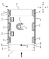
- the insertion portion 118 is provided on the back surface of the shelf tag mounting portion 113, and forms a notch with an open upper portion for holding the display board 131 as the second shelf tag.
- the display plate 131 is a relatively thin sheet-like member made of paper, resin, or the like for displaying an advertisement for a product or the like.
- the holding plate portion 119 is a flat plate-shaped portion of the back surface of the shelf tag mounting portion 113 that protrudes rearward and extends laterally below the left and right clip portions 117. It is preferable that the holding plate portion 119 has a flat plate shape in which the upper surface and the lower surface are parallel to each other and is substantially perpendicular to the back surface of the shelf tag mounting portion 113. This makes it easier to remove from the mold and facilitates manufacturing.
- the holding plate connecting portion 120 connects the base end of the holding plate portion 119 and the shelf tag mounting portion 113.
- the holding plate connecting portion 120 is thinner than the holding plate portion 119 in terms of the thickness which is the length in the vertical direction, and is provided with a plurality of through holes H (long holes long in the left and right in the present embodiment) penetrating in the vertical direction. There is.
- the holding plate portion 119 By connecting the holding plate portion 119 to the back surface of the shelf tag mounting portion 113 via such a holding plate connecting portion 120, the holding plate portion 119 can be easily separated from the shelf tag mounting portion 113. For example, by swinging the holding plate portion 119 up and down several times around the holding plate connecting portion 120 while holding the shelf tag mounting portion 113, the holding plate connecting portion 120 is easily brittlely broken. As a result, the holding plate portion 119 can be easily separated from the shelf tag mounting portion 113.
- the holding plate connecting portion 120 may be configured so that the holding plate portion 119 can be separated from the shelf tag mounting portion 113, and if it is thinner than the holding plate portion 119, a through hole may not be provided.
- the through hole is not limited to a large long hole that is long in the left-right direction as in the embodiment, but is relatively small in length in the left-right direction such as a columnar shape. It may be a hole.
- the holding plate connecting portion 120 may be perforated by providing a plurality of through holes arranged side by side at relatively short intervals in the left-right direction.
- the electronic shelf label 101 is pressed against the shelf label mounting portion 113 from the front of the shelf label holding portion 103 so that the rear wall portion 108 passes through the gap of the protrusion portion 115.
- the electronic shelf label 101 is a shelf label so that the upper rear wall portion 108 passes through the gap of the upper protrusion portion 115 and the lower rear wall portion 108 passes through the gap of the lower protrusion portion 115. It is pressed against the shelf tag mounting portion 113 from the front of the holding portion 103. At this time, the upper protrusion 115 passes through the gap of the upper rear wall portion 108, and the lower protrusion 115 passes through the gap of the lower rear wall portion 108.
- the protrusion 115 and the rear wall 108 are positioned, the protrusion 115 is positioned in the groove 105, and the rear wall 108 is the shelf tag mounting portion 113 and the protrusion.
- Positioned in the groove between 115. 11A and 11B are views of a state in which the electronic shelf label 101 is pressed against the shelf label attachment portion 113 in order to attach the electronic shelf label 101 to the shelf label holding portion 103, and the dotted line is a view of the electronic shelf label 101. Shows the back.
- the protrusion 115 can move in the left-right direction along the groove 105, and the rear wall portion 108 is along the groove between the shelf tag mounting portion 113 and the protrusion 115. It can move in the left-right direction.
- each of the protrusions 115 is positioned between the rear wall portion 108 and the step portion 106 and cannot move back and forth. Locked like this.
- each of the protrusions 115 is positioned between the rear wall portion 108 and the step portion 106 and cannot move back and forth. Locked like this.
- the electronic shelf tag 101 is held by the shelf tag holding unit 103, and the attachment of the electronic shelf tag 101 is completed.
- the electronic shelf label 101 is left on the left so that the upper rear wall portion 108 is located behind the gap of the upper protrusion 115 and the lower rear wall portion 108 is located behind the gap of the lower protrusion 115. Slide to the right or to the right. Then, by moving the electronic shelf tag 101 forward with respect to the shelf tag attaching portion 113, the electronic shelf tag 101 is removed from the shelf tag holding portion 103.
- the right end of the electronic shelf label 101 is extended to the left end of the shelf label holding unit 103, or the left end of the electronic shelf label 101 is attached to the shelf label holding unit 103. There is no need to slide it to the right end of.
- the electronic shelf tag 101 according to the present embodiment can be attached to and detached from the shelf tag holding portion 103 with a movement amount smaller than the movement amount of such a slide movement in the left-right direction.
- the brim portion 114 is continuously provided in the lateral direction. Further, the upper protrusion 115 protrudes downward from the upper brim portion, and the lower protrusion 115 protrudes upward from the brim portion protruding forward from the lower end of the shelf tag mounting portion 113.
- the electronic shelf tag 101 can be easily removed from the shelf tag holding unit 103.
- the spring portion 116 (pressing protrusion 121) moves the electronic shelf label 101 forward when the electronic shelf label 101 is attached to the shelf label holding portion 103. push.
- the shelf label holding unit 103 can firmly hold the attached electronic shelf label 101. Therefore, the electronic shelf tag 101 held by the shelf tag holding unit 103 can be made difficult to be removed from the shelf tag holding unit 103.
- the spring portion 116 may be any as long as it pushes the electronic shelf tag 101 forward, and the spring portion 116 may not be provided with the pressing protrusion 121.
- the electronic shelf label 101 is removed from the shelf label holding unit 103 by a relatively slight slide movement.
- the electronic shelf tag 101 may easily come off from the shelf tag holding portion 103 and fall to be damaged.
- a recess 132 forming a recess is provided on the back surface of the electronic shelf tag 101.
- the recess 132 is provided at a position where the electronic shelf tag 101 is pushed by the spring portion 116 (pressing protrusion 121) when the electronic shelf tag 101 is attached to the shelf tag holding portion 103. This makes it possible to make the electronic shelf label 101 held by the shelf label holding unit 103 even more difficult to remove from the shelf label holding unit 103.
- the insertion portion 118 is provided so as to form a notch with an open upper portion for holding the display plate 131.
- the display board 131 can be attached.
- Each of the left and right shaft portions 112 is positioned so as to be sandwiched between the left and right arm portions 110 from the left and right directions, and is inserted from below each of the left and right clip portions 117. Then, the shelf tag holding portion 103 is pressed downward against the arm portion 110.
- FIG. 13 is a view from the left of a state in which the shelf label holding portion 103 holding the electronic shelf label 101 is attached to the arm portion 110, and the arm portion 110 is shown by a dotted line.
- the holding plate portion 119 may remain connected to the shelf tag attaching portion 113 via the holding plate connecting portion 120, but the holding plate portion 119 is unnecessary. , May be separated as described above.
- FIG. 13 shows a state in which the holding plate portion 119 is separated, and the same applies to FIG.
- the shelf tag holding portion 103 attached to the arm portion 110 can rotate about the rotation axis P passing through the center of the left and right shaft portions 112.
- the stopper 130 of the shelf tag holding portion 103 is along the tip of the arm portion, as shown by the arcuate arrow in FIG. By moving, it can rotate about the rotation axis P with respect to the support member 102.
- FIG. 14 is a diagram showing an example of a state in which the shelf label holding unit 103 holding the electronic shelf label 101 is rotated so that the display unit 104 faces upward with the rotation axis P as the center.
- the display unit 104 when the display unit 104 is arranged so as to be inclined so as to face slightly upward, it may be easier for a customer or the like to purchase the product. Therefore, it is not preferable to incline the display unit 104 so as to face downward.
- the display unit 104 may face downward by touching the hand of a customer who purchases a product.
- the electronic shelf tag 101 weighs about 30 grams, which is heavier than the paper or resin shelf tag. Therefore, the shelf tag holding unit 103 holding the electronic shelf tag 101 has a display unit due to its own weight. The 104 may point downwards.
- the center of gravity of a general electronic shelf label 101 is often located at or near the center in the vertical direction, and as shown in FIG. 13, when the rotation axis P is viewed from the left, the electron is electron. It may be provided above the center of gravity G of the shelf tag holding portion 103 holding the shelf tag 101. In such a case, even if the electronic shelf label 101 is arranged so that the display unit 104 is tilted slightly upward as shown in FIG. 14, there is a high possibility that the display unit 104 faces downward due to its own weight.
- the stopper 130 protruding to the left is provided on the left hanging portion 128 as described above. Therefore, by contacting the lower end of the left arm portion 110 behind the rotation axis P, the shelf tag holding portion 103 does not rotate beyond a predetermined range in the direction in which the display portion 104 faces downward. Locked to.
- the rotation of the display unit 104 in the downward direction means a clockwise rotation about the rotation axis P in FIGS. 13 and 14.
- the shelf tag holding portion 103 includes the stopper 130 and the arm portion 110 so that the display unit 104 does not rotate in the direction toward the front and further downward. Locked by contact.
- the shelf label attaching device 100 having a relatively simple structure can prevent the display unit 104 of the electronic shelf label 101 from rotating in a downward direction beyond a predetermined range.
- the stopper is provided at a position away from the center of gravity of the shelf tag holding portion in the left-right direction.
- the stopper 130 By moving away from the center of gravity G in the left-right direction, it is possible to prevent the display unit 104 of the electronic shelf label 101 from rotating in a downward direction beyond a predetermined range with a relatively small force. Therefore, even if the stopper 130 is relatively small, rotation can be sufficiently suppressed.
- the shelf tag attaching device 100 having a simple structure makes it possible to prevent the display unit 104 of the electronic shelf tag 101 from rotating in a downward direction beyond a predetermined range.
- the center of gravity of the electronic shelf label 101 is often located near the center in the left-right direction. Therefore, the center of gravity G of the shelf label holding portion 103 holding the electronic shelf label 101 is also approximately located in the left-right direction. Often located near the center.
- the stopper 130 protrudes to the left from the left end of the left hanging portion 128. This means that the stopper 130 is provided at a position that is often the farthest in the left-right direction from the center of gravity G of the shelf label holding portion 103 that holds the electronic shelf label 101.
- the shelf label attaching device 100 having a simpler structure makes it possible to prevent the display unit 104 of the electronic shelf label 101 from rotating in a downward direction beyond a predetermined range.
- the length L1 is the vertical length between the upper end of the front plate 125 and the lower surface of the shelf 122.
- the length L2 is the length in the vertical direction between the upper surface of the holding plate portion 119 and the bearing portion 129.
- the first attachment method to the second product shelf MS2 is a method of attaching the shelf tag holding portion 103 to the second product shelf MS2 when the length L1 is the length L2 or less.
- FIG. 15A shows, as an example of this case, an example in which the length L1 and the length L2 are substantially equal to each other.
- the front plate 125 provided on the second product shelf MS2 is inserted from below between the clip portion 117 and the back surface of the shelf tag mounting portion 113. Then, the holding plate portion 119 is arranged under the shelf 122.
- the front plate 125 provided on the second product shelf MS2 is sandwiched between the clip portion 117 and the back surface of the shelf tag mounting portion 113, and is held by the holding plate portion 119.
- the shelf label holding unit 103 that holds the electronic shelf label 101 is attached to the second product shelf MS2.
- the electronic shelf tag 101 attached to the second product shelf MS2 via the shelf tag holding section 103 is held not only by sandwiching the front plate 125 but also by the holding plate section 119 as described above. That is, even if a force that causes the display unit 104 to swing upward or downward or a force that moves upward is applied, the holding plate unit 119 is the second product shelf MS2 (in the example of FIG. 15A, the fixing unit 126). ) Contact with the lower surface, limiting the range of rocking or movement.
- the electronic shelf label 101 is difficult to be removed from the second product shelf MS2. Therefore, it is possible to reduce the possibility that the electronic shelf label 101 will fall and be damaged.
- the second attachment method to the second product shelf MS2 is a method of attaching the shelf tag holding portion 103 to the second product shelf MS2 when the length L1 is longer than the length L2, and FIG. 15B shows this case.
- An example is shown. In this case, the holding plate portion 119 is separated. Then, the front plate 125 provided on the second product shelf MS2 is inserted from below between the clip portion 117 and the back surface of the shelf tag mounting portion 113.
- the front plate 125 provided on the second product shelf MS2 is sandwiched between the clip portion 117 and the back surface of the shelf tag mounting portion 113, so that the front plate 125 owns itself. It bends due to elasticity. Therefore, the front surface and the rear surface of the front plate 125 come into contact with the back surface of the shelf tag mounting portion 113 and the clip portion 117, respectively, with the elastic force of the front plate 125 applied. As a result, the shelf label holding unit 103 that holds the electronic shelf label 101 is attached to the second product shelf MS2. When removing the clip portion 117, the clip portion 117 may be pulled out from between the clip portion 117 and the back surface of the shelf label mounting portion 113, for example, by holding the electronic shelf tag 101 and moving it upward.
- the electronic shelf tag 101 can be attached to the first product shelf MS1 and the second product shelf MS2 having different attachment methods. Further, as described above, since the holding plate portion 119 can be easily separated from the shelf label attaching portion 113, the electronic shelf label 101 can be attached to various second product shelves MS2.
- the shelf tag holding portion 103 uses the bearing portion 129 as the first fitting portion, which is one of the shaft portion and the bearing portion for rotating the support member 102 around the rotation shaft P.
- the example to have was explained. Further, an example has been described in which the support member 102 has a shaft portion 112 as a second fitting portion which is the other of the shaft portion and the bearing portion for rotating with respect to the support member 102 about the rotation shaft P.
- the shelf tag holding portion 103 may have a shaft portion as a first fitting portion, and the support member 102 may have a bearing portion as a second fitting portion. This also has the same effect as that of the embodiment.
- the right hanging part 128 is shorter than the left hanging part 128, and the stopper 130 is provided only on the long left hanging part 128 and is located below the lower end of the right side hanging part 128.
- the shelf tag holding portions 103 can be arranged at narrow intervals so as to be substantially in contact with each other in the left-right direction.
- the right hanging portion 128 may be provided with the same length as the left hanging portion 128, and the stopper 130 may be provided on both the left and right hanging portions 128.
- stopper 130 protrudes from the left end of the left hanging portion 128 to the left and thus protrudes from the side portion of the shelf tag holding portion 103 has been described. However, it does not have to protrude from the side of the shelf tag holding portion 103.
- the outer dimensions of the left and right arm portions 110 in the left-right direction may be accommodated inside the left and right clip portions 117, and the shaft portion 112 of the arm portion 110 may extend outward, unlike the embodiment.
- a shaft portion 112 extending to the left from the left end surface of the left arm portion 110 and a shaft portion 112 extending to the right from the right end surface of the right arm portion 110 may be provided.
- the shaft portion 112 provided on the left arm portion 110 is inserted into the left bearing portion 129 from the right side, and the shaft portion 112 provided on the right arm portion 110 is the right bearing portion. It is good to insert it in 129 from the left side.
- the stopper 130 is moved from the right end of the left hanging portion 128 to the right, that is, in the left-right direction. May extend toward the center of the shelf tag mounting portion 113.
- the positions of the stopper 130 in the front-rear direction and the up-down direction may be the same as those in the embodiment.
- the shelf tag holding portion 103 is brought into contact with the stopper 130 and the arm portion 110 so that the display unit 104 does not rotate in the direction toward the front and further downward, as in the embodiment. Can be locked.
- the shelf label attaching device 100 having a relatively simple structure makes it possible to prevent the display unit 104 of the electronic shelf label 101 from rotating in a downward direction beyond a predetermined range.
- the lateral positions of the gaps are different from each other in the vertical direction. May be.
- FIG. 17 shows an example of the shelf tag holding unit 203 according to this modified example.
- the combination of the upper groove portion 105 and the protrusion portion 115 that fits into the groove portion 105 is the same as that of the embodiment.
- the position where the combination of the lower groove portion 205 and the protrusion portion 215 fitted to the groove portion 205 is provided is different from the embodiment.
- the lower groove portion 205 (rear wall portion 208) is provided below the gap of the upper groove portion 105 (rear wall portion 108). Further, the lower protrusion 215 is provided below the gap of the upper protrusion 115.
- the protrusions 115 and 215 can be moved in the left-right direction along the groove 105, and the rear wall portion 108 is a shelf tag mounting portion. It can move laterally along the groove between 113 and the protrusions 115, 215.
- the electronic shelf tag 201 cannot be attached to the shelf tag holding portion 203 by reversing the top and bottom. Therefore, it is possible to prevent the electronic shelf label 201 from being attached to the shelf label holding portion 203 by erroneously reversing the vertical direction.
- both the combination of the upper groove 105 and the protrusion 115 fitted in the groove 105 and the combination of the lower groove 105 and the protrusion 115 fitted in the groove 105 are discretely provided. I explained the example.
- FIG. 18 is a front view of the shelf tag holding portion 303 according to this modification.
- a protrusion 315 that fits into the lower groove portion 105 is continuously provided.
- an example of the position where the back surface of the electronic shelf label 101 is arranged when the electronic shelf label 101 is pressed against the shelf label attachment portion 113 in order to attach the electronic shelf label 101 to the shelf label holding portion 303 is shown by a dotted line. show.
- the electronic shelf label 101 is slightly tilted so that the lower protrusion 315 is fitted into the lower groove 105 and then the upper rear wall 108 passes through the gap of the upper protrusion 115. It is preferable that the electronic shelf tag 101 is pressed against the shelf tag mounting portion 113 from the front of the shelf tag holding portion 103.
- the protrusions 115 and 315 can move in the left-right direction along the groove 105, and the rear wall portion 108 is between the shelf tag mounting portion 113 and the protrusions 115 and 315. Can move left and right along the groove of.
- a shelf label holder for holding the first shelf label, A support member that rotatably supports the shelf label holding portion around a rotation axis extending in the lateral direction of the first shelf label is provided.
- the shelf tag holding portion has a first fitting portion that is one of a shaft portion and a bearing portion for rotating around the rotation axis with respect to the support member.
- the support member is provided with a second fitting portion that is the other side of the shaft portion and the bearing portion, and has an arm portion that sandwiches the first fitting portion from the lateral direction.
- the shelf label holding portion has a shelf label mounting having a stopper that locks the display surface of the first shelf label so as not to rotate beyond a predetermined range in a direction facing downward by contacting the arm portion.
- Device
- the arm portion has a semicircular tip and has a semicircular tip.
- the shelf according to any one of 1 to 6 above, wherein the shelf tag holding portion rotates about the rotation axis with respect to the support member by moving the stopper along the tip of the arm portion. Tag mounting device.
- the first shelf label is the shelf label mounting device according to any one of 1 to 7 above, which is an electronic shelf label.
- shelf tag mounting device according to any one of 1 to 8 above, wherein the shelf tag holding portion has an insertion section for holding the inserted second shelf label.
- the shelf tag holding unit is The shelf tag attachment part to which the first shelf tag is attached, and A holding plate portion that protrudes rearward of the shelf tag mounting portion and extends laterally, and a holding plate portion.
- the shelf tag mounting device according to any one of 1 to 9 above, which has a holding plate connecting portion that detachably connects the holding plate portion from the shelf tag mounting portion.
- the shelf tag holding unit is The shelf tag mounting device according to any one of 10 to 12, wherein the holding plate portion has a flat plate shape in which the upper surface and the lower surface are parallel to each other.
Landscapes
- Physics & Mathematics (AREA)
- General Physics & Mathematics (AREA)
- Engineering & Computer Science (AREA)
- Theoretical Computer Science (AREA)
- Display Racks (AREA)
Priority Applications (2)
| Application Number | Priority Date | Filing Date | Title |
|---|---|---|---|
| JP2022539569A JP7772451B2 (ja) | 2020-07-31 | 2021-07-29 | 棚札取付装置 |
| US18/017,612 US12426725B2 (en) | 2020-07-31 | 2021-07-29 | Shelf tag attachment apparatus |
Applications Claiming Priority (2)
| Application Number | Priority Date | Filing Date | Title |
|---|---|---|---|
| JP2020130341 | 2020-07-31 | ||
| JP2020-130341 | 2020-07-31 |
Publications (1)
| Publication Number | Publication Date |
|---|---|
| WO2022025191A1 true WO2022025191A1 (ja) | 2022-02-03 |
Family
ID=80036358
Family Applications (1)
| Application Number | Title | Priority Date | Filing Date |
|---|---|---|---|
| PCT/JP2021/028120 Ceased WO2022025191A1 (ja) | 2020-07-31 | 2021-07-29 | 棚札取付装置 |
Country Status (3)
| Country | Link |
|---|---|
| US (1) | US12426725B2 (https=) |
| JP (2) | JP7529273B2 (https=) |
| WO (1) | WO2022025191A1 (https=) |
Citations (4)
| Publication number | Priority date | Publication date | Assignee | Title |
|---|---|---|---|---|
| JP2002500900A (ja) * | 1997-12-02 | 2002-01-15 | プライサー エイビー | ラベルホルダー |
| JP2005040211A (ja) * | 2003-07-24 | 2005-02-17 | Kokuyo Co Ltd | 陳列用具及びその上部ユニット |
| JP3128221U (ja) * | 2006-10-19 | 2006-12-28 | カワマタ化成株式会社 | 値札保持具 |
| JP3186408U (ja) * | 2013-07-24 | 2013-10-03 | 株式会社イシダ | 電子棚札及びそれに取り付けるpop表示具 |
Family Cites Families (13)
| Publication number | Priority date | Publication date | Assignee | Title |
|---|---|---|---|---|
| US6269571B1 (en) * | 1998-07-24 | 2001-08-07 | Trion Industries, Inc. | Dual purpose label holder adapted for mounting on a cross bar or mounting plate of a merchandise display hook |
| SE513109C2 (sv) * | 1998-11-06 | 2000-07-10 | Hl Display Ab | Vinkelinställbar etiketthållare för varuexponeringsstativ |
| FR2832840B1 (fr) * | 2001-11-27 | 2003-12-26 | Store Electronic Systems Techn | Systeme d'etiquetage electronique destine a etre porte par la traverse d'un presentoir a broche |
| US7089695B2 (en) * | 2003-10-15 | 2006-08-15 | Fast Industries, Ltd. | Hinged label holder |
| FR2861884B1 (fr) * | 2003-10-31 | 2006-02-24 | Joalpe Ind De Expositores Sa | Dispositif d'affichage, notamment pour l'affichage electronique des prix |
| DE102004017498B4 (de) * | 2004-04-08 | 2008-02-07 | Checkpoint Systems, Inc. | Adapter zur Befestigung eines elektronischen Regaletiketts an einem Blisterhaken |
| JP5035828B2 (ja) | 2006-12-18 | 2012-09-26 | 河淳株式会社 | 表示用ホルダ |
| JP3137183U (ja) | 2007-09-04 | 2007-11-15 | 河淳株式会社 | ダブルフックハンガー用アダプター及びこれを装着したダブルフックハンガー |
| JP3139238U (ja) | 2007-11-16 | 2008-02-07 | 河淳株式会社 | 表示具 |
| JP5547179B2 (ja) | 2009-05-01 | 2014-07-09 | 株式会社オプトエレクトロニクス | 電子棚札 |
| US11227293B2 (en) * | 2018-08-16 | 2022-01-18 | Best Brands Consumer Products, Inc. | Digital price display |
| SE543918C2 (en) * | 2019-04-02 | 2021-09-21 | Pricer Ab | Electronic shelf label and sign |
| CA3184427C (en) * | 2022-01-06 | 2025-07-08 | Carl Pomerantz | APPARATUS FOR INHIBITING THE DISLOCATION OF AN ELECTRONIC TAG ASSEMBLY |
-
2021
- 2021-03-16 JP JP2021042250A patent/JP7529273B2/ja active Active
- 2021-07-29 WO PCT/JP2021/028120 patent/WO2022025191A1/ja not_active Ceased
- 2021-07-29 JP JP2022539569A patent/JP7772451B2/ja active Active
- 2021-07-29 US US18/017,612 patent/US12426725B2/en active Active
Patent Citations (4)
| Publication number | Priority date | Publication date | Assignee | Title |
|---|---|---|---|---|
| JP2002500900A (ja) * | 1997-12-02 | 2002-01-15 | プライサー エイビー | ラベルホルダー |
| JP2005040211A (ja) * | 2003-07-24 | 2005-02-17 | Kokuyo Co Ltd | 陳列用具及びその上部ユニット |
| JP3128221U (ja) * | 2006-10-19 | 2006-12-28 | カワマタ化成株式会社 | 値札保持具 |
| JP3186408U (ja) * | 2013-07-24 | 2013-10-03 | 株式会社イシダ | 電子棚札及びそれに取り付けるpop表示具 |
Also Published As
| Publication number | Publication date |
|---|---|
| JPWO2022025191A1 (https=) | 2022-02-03 |
| JP7529273B2 (ja) | 2024-08-06 |
| JP2022027429A (ja) | 2022-02-10 |
| US20230276956A1 (en) | 2023-09-07 |
| JP7772451B2 (ja) | 2025-11-18 |
| US12426725B2 (en) | 2025-09-30 |
Similar Documents
| Publication | Publication Date | Title |
|---|---|---|
| JP2018205399A (ja) | 表示装置 | |
| JP2003233323A (ja) | 表示用ホルダ | |
| WO2022025192A1 (ja) | 棚札取付装置 | |
| WO2022025191A1 (ja) | 棚札取付装置 | |
| JP7572072B2 (ja) | 商品棚 | |
| KR200488700Y1 (ko) | 상품정보 태그용 조립식 홀더 | |
| JP3139238U (ja) | 表示具 | |
| JPWO2022025192A5 (https=) | ||
| JP4580076B2 (ja) | サンプルホルダー | |
| JP3107283U (ja) | ポップクリップ及びポップクリップ装着ポップ紙保持装置 | |
| JP5451992B2 (ja) | Popホルダー | |
| JP2020078460A (ja) | 表示装置 | |
| JP2006163041A (ja) | 陳列商品の情報表示具 | |
| JP2002116703A (ja) | 表示用ホルダ | |
| JP3177436U (ja) | 商品陳列具用ポップ表示具 | |
| JP4656708B2 (ja) | 陳列商品の情報表示具及びその使用方法 | |
| JP2005192587A (ja) | 商品陳列棚用表示装置 | |
| JP3799051B1 (ja) | 平型商品ケース用商品情報表示具 | |
| JP2015031840A (ja) | 物品保持具及びルーペ | |
| JPWO2022025191A5 (https=) | ||
| JP2007117107A (ja) | プライスカードホルダーを有するプライス表示装置 | |
| JP2003330382A (ja) | 電子pop、及びモニタの取付具 | |
| JP2001343918A (ja) | 広告物吊下げ具 | |
| JP2001255821A (ja) | 展示装置 | |
| JP2020201786A (ja) | 自動販売機のサンプル台 |
Legal Events
| Date | Code | Title | Description |
|---|---|---|---|
| 121 | Ep: the epo has been informed by wipo that ep was designated in this application |
Ref document number: 21850392 Country of ref document: EP Kind code of ref document: A1 |
|
| ENP | Entry into the national phase |
Ref document number: 2022539569 Country of ref document: JP Kind code of ref document: A |
|
| NENP | Non-entry into the national phase |
Ref country code: DE |
|
| 122 | Ep: pct application non-entry in european phase |
Ref document number: 21850392 Country of ref document: EP Kind code of ref document: A1 |
|
| WWG | Wipo information: grant in national office |
Ref document number: 18017612 Country of ref document: US |