WO2022024317A1 - 保守システム、データ処理装置、保守方法、および、プログラム - Google Patents
保守システム、データ処理装置、保守方法、および、プログラム Download PDFInfo
- Publication number
- WO2022024317A1 WO2022024317A1 PCT/JP2020/029313 JP2020029313W WO2022024317A1 WO 2022024317 A1 WO2022024317 A1 WO 2022024317A1 JP 2020029313 W JP2020029313 W JP 2020029313W WO 2022024317 A1 WO2022024317 A1 WO 2022024317A1
- Authority
- WO
- WIPO (PCT)
- Prior art keywords
- data
- unit
- observable
- processing device
- classification information
- Prior art date
- Legal status (The legal status is an assumption and is not a legal conclusion. Google has not performed a legal analysis and makes no representation as to the accuracy of the status listed.)
- Ceased
Links
Images




Classifications
-
- G—PHYSICS
- G06—COMPUTING OR CALCULATING; COUNTING
- G06F—ELECTRIC DIGITAL DATA PROCESSING
- G06F13/00—Interconnection of, or transfer of information or other signals between, memories, input/output devices or central processing units
Definitions
- the present invention relates to a maintenance system, a data processing device, a maintenance method, and a program.
- Non-Patent Document 1 describes an autonomous control loop that autonomously determines the operation by simply incorporating a new operation component into the system by making the maintenance operation function into a component and automating it as a technology for automating the service maintenance work.
- a method has been proposed. In the autonomous control loop method, messages are sent and received between operating components divided by function. Each operating component operates autonomously based on the received message.
- Non-Patent Document 1 there is no method for grasping the behavior of operating parts, and operating parts operate autonomously at their own discretion, resulting in a black box.
- the following problems occur, and it is difficult to establish a policy to follow the addition of new services and changes in service specifications. That is, it is difficult to grasp the details of the operation contents (test, analysis, recovery treatment) of each operation component 10, and it is difficult to judge whether appropriate treatment is performed. Even if a defect occurs in an operating part, the behavior and cause at the time of the defect cannot be grasped. Even when adding operational parts to follow new services and changes in service specifications, it is difficult to ensure normality because tests and operation checks cannot be performed.
- the present invention has been made in view of the above circumstances, and an object of the present invention is a maintenance system, a data processing device, and maintenance that support policy formulation for acquiring the behavior of operating parts and following changes in services.
- the method and the program are to be provided.
- one aspect of the present invention is a maintenance system, which includes a plurality of operation parts that operate autonomously by transmitting and receiving messages, and a data processing device, and each operation part is the operation.
- An acquisition unit that acquires observable data for grasping the state of parts, a data transfer unit that stores the observable data in a storage unit when the type of received data is the observable data, and a data transfer unit.
- the data processing device comprises a classification unit that sets classification information in the observable data of the storage unit, and a correlation unit that correlates the observable data in which the classification information is set by using the classification information. And.
- One aspect of the present invention is a data processing device, in which a classification unit that sets classification information for observable data acquired by a plurality of operating components that transmit and receive messages and operate autonomously, and the classification information are provided. It includes a correlation unit that correlates the set observability data using the classification information, and a display unit that displays the correlated observability data in a designated pattern.
- One aspect of the present invention is a maintenance method performed by a maintenance system, wherein the maintenance system includes a plurality of operating parts that operate autonomously by transmitting and receiving messages, and a data processing device.
- the data processing apparatus performs a step of setting classification information in the observable data of the storage unit and a step of correlating the observable data in which the classification information is set by using the classification information. conduct.
- One aspect of the present invention is a program that causes a computer to function as the above data processing device.
- the present invention it is possible to provide a maintenance system, a data processing device, a maintenance method, and a program that acquire the behavior of operating parts and facilitate the response to changes in services.
- FIG. 1 is a diagram showing an example of the overall configuration of the maintenance system of the present embodiment.
- the maintenance system of the present embodiment maintains a linked service (not shown) in which a plurality of services are linked. Specifically, the maintenance system monitors the quality of linked services and the presence or absence of abnormalities due to the effects of equipment failures, and performs analysis and recovery as necessary.
- an autonomous control loop method is adopted in which a plurality of operation components 10 having no connection relationship with each other actively check the status of each service and alarm, and autonomously determine and execute necessary processing. ing.
- the maintenance system shown in the figure includes a plurality of operation parts 10 and a data processing device 20.
- the operation component 10 is a device or process that operates autonomously by transmitting and receiving messages.
- Each operation component 10 is made into a component in units of maintenance functions, and each has a specific maintenance function.
- the operation component 10 is classified into functional types such as information collection, information processing, information analysis, testing, recovery measures, and maintenance personnel. The outline of each type of operational parts is shown below.
- [Information collection] Collect information from the linked service (service environment) to be maintained.
- [Information analysis] Performs information analysis such as classification, prediction, and state estimation for abnormality judgment and clustering, and generation of analysis results.
- a maintenance person grasps the operating status of the operation component 10 and provides a user interface for controlling the operation component 10.
- the maintenance system may not include all the operation components 10 of the above six function types, or may include the operation components 10 other than the above function types. Further, the maintenance system may include a plurality of operation components 10 having the same function type. For example, when maintaining a linked service in which a plurality of services are linked, the operation component 10 of the above-mentioned function type may be provided for each of the plurality of services.
- the operation component 10 executes an action when it receives a message addressed to itself.
- the action indicates the operation content of the operation component 10, and corresponds to each function when the operation component 10 is made into a component in units of maintenance functions. If the action is successfully executed, the operation component 10 sends a message to the message bus 30, and if the action execution fails, the operation component 10 completes the operation without sending the message.
- the illustrated operation component 10 includes a message transmission / reception unit 11, a data / state storage unit 12, an ignition rule storage unit 13, a rule execution unit 14, an action execution unit 15, a data transfer unit 16, and an acquisition unit 17. Be prepared.
- the data transfer unit 16 transmits and stores the observable data in the storage unit 21 of the data processing device 20. Specifically, the data transfer unit 16 controls the data transmission destination according to the type of data to be transmitted to the outside.
- the data transfer unit 16 transmits and stores the outward data of the type observable data sent from the acquisition unit 17 to the storage unit 21 via the data bus 40. Further, the data transfer unit 16 transmits the outward data of the type message sent from the message transmission / reception unit 11 to the message bus 30. The data transfer unit 16 sends inward data of the type message received via the message bus 30 to the message transmission / reception unit 11.
- the acquisition unit 17 acquires observability data for grasping the state of the operation component 10, and sends the acquired observability data to the data transfer unit 16.
- Observable data includes at least one of Logging, Metrics, and Tracing, which indicates coordination between operational components.
- Logging is an operation log of its own operation component 10. Logging includes, for example, an operation history such as when and what kind of message was sent or received, when and what kind of action was executed, when and what kind of error was output, and so on.
- the acquisition unit 17 periodically acquires Logging output to a log file (not shown) at a predetermined timing.
- Metrics is the resource information of its own operation component 10. Metrics include, for example, information such as CPU usage, memory usage, and traffic volume.
- the acquisition unit 17 periodically acquires Metrics at a predetermined timing using an OS or the like.
- Tracing is information that indicates cooperation between operational parts.
- the acquisition unit 17 cooperates with the message transmission / reception unit 11, and uses the messages transmitted / received by the message transmission / reception unit 11 to use information indicating what kind of operation cooperation has occurred between the operating components as tracing. get.
- the source and destination operation components 10 are set in the messages sent and received between the operation components. Therefore, the acquisition unit 17 can acquire the operation linkage between the operation parts (for example, the cooperation in the order of the operation component A ⁇ the operation component B ⁇ the operation component C).
- the observability data of this embodiment includes information on the service to be processed and information on the operation performed by its own operation component 10.
- the message transmission / reception unit 11 receives a message via the message bus 30 and the data transfer unit 16. Further, when the action by the action execution unit 15 is successful, the message transmission / reception unit 11 creates a message based on the execution result of the action and transmits it to the message bus 30 via the data transfer unit 16. If the action by the action execution unit 15 fails, the message transmission / reception unit 11 does not send a message.
- the data / state storage unit 12 holds data and a state such as a received message and an execution result of the action execution unit 15.
- the action execution unit 15 may use the data and the state of the data / state storage unit 12 when executing the action. Further, the data / state storage unit 12 may hold data acquired from a common data storage unit (not shown), or temporarily holds data to be stored in the common data storage unit and stores the data in the common data storage unit. May be stored.
- the common data storage unit holds information commonly used by each operating component 10.
- the action execution unit 15 may execute an action by using the data and the state held by the common data storage unit.
- the ignition rule storage unit 13 holds an ignition rule in which information for specifying an action to be executed is individually defined for each operation component 10.
- the firing rule may specify an action to be executed according to the type of the operating component 10 that is the source of the received message.
- the operation component 10 of "information processing” has an ignition rule that specifies an action to be executed when the transmission source receives the message of the operation component 10 of "information collection", and the operation component 10 of the transmission source "test”. Holds a firing rule that specifies the action to take when the message is received.
- the rule execution unit 14 fires the received message and instructs the action execution unit 15 to execute the action. Specifically, when the message transmission / reception unit 11 receives a message addressed to itself, the rule execution unit 14 acquires the ignition rule stored in the ignition rule storage unit 13 and notifies the action execution unit 15 of the action to be executed. do.
- the action execution unit 15 receives an instruction from the rule execution unit 14, refers to the data held by the data / state storage unit 12 and the data held by the common data storage unit, and performs the action notified by the rule execution unit 14. Run.
- the message transmission / reception unit 11 sends a message to the data transfer unit 16.
- the action by the action execution unit 15 may fail due to factors such as lack of data. If the action execution unit 15 fails to execute the action, no message is sent.
- each operation component 10 in order to acquire the observability data of the maintenance system by the autonomous control loop method, each operation component 10 includes a common acquisition unit 17. Further, the operation component 10 includes a common data transfer unit 16 in order to link a plurality of types of data such as messages and observable data with the outside.
- the operation component 10 of the present embodiment the cooperation with the outside is left to the data transfer unit 16, and the internal processing can be limited to the internal communication with the data transfer unit 16. Therefore, in the present embodiment, the data transfer process can be generalized in each operation component 10, and when a new service is added to the linked service, the new operation component 10 can be quickly added. can.
- the data processing device 20 presents the operation (behavior) of the operation component 10 to the user by using the observable data acquired by each operation component 10.
- the illustrated data processing device 20 includes a storage unit 21, a classification unit 22, a correlation unit 23, and a display unit 24.
- the data processing device 20 may be mounted by a plurality of devices.
- the storage unit 21, the classification unit 22, the correlation unit 23, and the display unit 24 may be individual devices (for example, a server).
- Observable data transmitted from each operating component 10 is stored in the storage unit 21.
- the classification unit 22 sets the classification information in the observable data of the storage unit 21. Specifically, the classification unit 22 classifies the observable data in order to utilize the observable data, and makes the data easy to handle. In the present embodiment, the classification unit 22 automatically analyzes the observable data each time the observable data is stored in the storage unit 21, and the observable data includes a data type, a service type, and an operation type. Add classification information such as.
- FIG. 2 is a diagram showing an example of an observable record stored in the storage unit 21.
- the illustrated observable record includes an operation component ID, an acquisition time, observability data, a data type, a service type, and an operation type.
- the acquisition unit 17 of the operation component 10 adds the observability data obtained by adding the operation component ID for identifying its own operation component 10 and the acquisition time when the observability data is acquired to the acquired observability data.
- the classification unit 22 adds classification information (data type, service type, operation type) to each observable data stored in the storage unit 21.
- the classification unit 22 determines the data type from the data format of the observable data, and sets the corresponding data type (Logging, Metrics, Tracing).
- the classification unit 22 acquires the service (service information) to be processed at the time of acquiring the observable data from the observable data, and sets the acquired service as a service type.
- the classification unit 22 acquires the operation (operation information) performed by the operation component 10 at the time of acquiring the observable data from the observable data, and sets the acquired operation as the operation type.
- the correlation unit 23 correlates the observable data stored in the storage unit 21 and to which the classification information is added in order to utilize the observability data, using the classification information.
- the correlation unit 23 stores the correlated result in the storage unit 21.
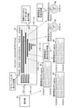
- FIG. 3 shows an example of a correlation diagram in which the observable data of the storage unit 21 is correlated.
- the correlation unit 23 correlates the observable data of Logging, Metrics and Tracing according to the following association rules.
- the user (operator, etc.) of the data processing device 20 can perform what kind of operation at any time for the automatic processing of failure detection and service recovery by the maintenance system, for example. It is possible to grasp the flow of autonomous control that fluctuates. In addition, the user can grasp the operating status (operating status) of the maintenance system and closely examine the coordination between the operating parts (deficiency of coordination, bias of load, etc.).
- the display unit 24 displays the observable data correlated by the correlation unit 23 in a pattern specified by the user. Specifically, the display unit 24 provides the user with the correlated observability data in the unit (pattern) required by the user in order to utilize the observability data collected by each operation component 10. Present. For example, the display unit 24 may display the correlated observable data in the following pattern.
- FIG. 4 is an example of observability data of each pattern displayed by the display unit 24.
- the tracing graph 51 of "service A” and "operation 001" is shown.
- Graph 51 shows the state of cooperation between operating parts.
- the vertical axis shows the order in which the operation components 10 are linked in messaging. In the illustrated Gulag 51, it is shown that the operation parts A ⁇ the operation parts B ⁇ the operation parts C ⁇ the operation parts D ⁇ ... Are linked in this order.
- the display unit 24 sets the vertical axis using Tracing.
- the horizontal axis (horizontal bar) indicates the time during which each operating component 10 has operated.
- the display unit 24 acquires the operating time from the Logging correlated with the Tracing of "Operation 001" and sets the horizontal axis.
- the operation is established by the autonomous cooperation of the operation components 10. That is, in the tracing graph 51, the cooperation (operation flow) between the operating parts is shown. As a result, the user can grasp the flow of the executed operation.
- the graph 51 of the pattern 6 is generated as many as the number of operations performed.
- the observable data for each operation component 10 and data type is displayed.
- Logging 53 of the operation component A, Metrics 56 of the operation component B, and the like are displayed.
- the display unit 24 may receive the user's instruction input to the tracing graph 51 as the pattern 4 and display the correlated observable data. For example, when the horizontal axis of the operation component B is specified, the display unit 24 may display Metrics 56 of the operation component B correlated with the Tracing of "Service A" and "Operation 001".
- FIG. 5 is a sequence diagram showing the operation of the maintenance system of the present embodiment.
- S11 to S18 indicate the process of acquiring, classifying, and correlating observable data.
- S21 to 24 indicate display processing of observable data.
- the acquisition unit 17 of the operation component 10 periodically acquires the observability data of its own operation component 10 at a predetermined timing (S11), and sends the acquired observability data to the data transfer unit 16 (S12). ..
- the data transfer unit 16 analyzes the data (observable data) transmitted in S11 and determines the data type (S13). When the data type is observable data, the data transfer unit 16 transfers the received observable data to the storage unit 21 of the data processing device 20 and stores it in the storage unit 21 (S14).
- the storage unit 21 notifies the classification unit 22 that the observable data has been stored (S15).
- the classification unit 22 adds classification information to the observable data stored in S14 by the notification of S15 (S16).
- the storage unit 21 notifies the correlation unit 23 that the classification information has been added to the observable data in S16 (S17).
- the correlation unit 23 correlates the observable data to which the classification information is added by the notification of S17 with other observable data, and stores the correlation result in the storage unit 21 (S18).
- the user transmits a display request specifying one of the patterns to the display unit 24 of the data processing device 20 at a desired timing (S21). Specifically, the user terminal 6 transmits the display request input by the user to the data processing device 20 via the network.
- the display unit 24 Upon receiving the display request, the display unit 24 searches for observable data required for the pattern specified in the display request (S22) and acquires it from the storage unit 21 (S23). The display unit 24 edits the acquired observability data in order to display it in a designated display pattern, and displays (presents) it on the user terminal 6 (S24).
- the maintenance system of the present embodiment described above includes a plurality of operation components 10 that operate autonomously by transmitting and receiving messages, and a data processing device 20, and each operation component 10 grasps the state of the operation component 10. It is provided with an acquisition unit 17 for acquiring observable data for the purpose of data transfer, and a data transfer unit 16 for storing the observable data in the storage unit 21 when the type of received data is the observable data.
- the data processing device 20 includes a classification unit 22 that sets classification information in the observable data of the storage unit 21, and a correlation unit 23 that correlates the observable data in which the classification information is set by using the classification information. To prepare for.
- the present embodiment it is possible to acquire the behavior of the operation component and easily respond to the change of the service.
- the autonomous control loop method it is possible to support the addition of new services and the formulation of policies for following changes in the specifications of existing services. Therefore, in the present embodiment, it is possible to easily determine a policy to follow the addition of a new service or the change of the service specification.
- a general-purpose computer system as shown in FIG. 6 can be used.
- the illustrated computer system is a CPU (Central Processing Unit, processor) 901, a memory 902, a storage 903 (HDD: Hard Disk Drive, SSD: Solid State Drive), a communication device 904, an input device 905, and an output device. It is equipped with 906.
- the memory 902 and the storage 903 are storage devices. In this computer system, each function of each device is realized by executing a predetermined program loaded on the memory 902 by the CPU 901.
- each function of the operation component 10 and the data processing device 20 is performed by the CPU of the operation component 10 in the case of the program for the operation component 10 and the CPU of the data processing device 20 in the case of the program for the data processing device 20. It is realized by executing.
- operation component 10 and the data processing device 20 may be mounted on one computer each, or may be mounted on a plurality of computers. Further, the operation component 10 and the data processing device 20 may be virtual machines mounted on a computer.
- the program for the operation component 10 and the program for the data processing device 20 are stored in a computer-readable recording medium such as an HDD, SSD, USB (Universal Serial Bus) memory, CD (Compact Disc), DVD (Digital Versatile Disc). It can be delivered over the network.
- a computer-readable recording medium such as an HDD, SSD, USB (Universal Serial Bus) memory, CD (Compact Disc), DVD (Digital Versatile Disc). It can be delivered over the network.
- the present invention is not limited to the above embodiment, and many modifications can be made within the scope of the gist thereof.
Landscapes
- Engineering & Computer Science (AREA)
- Theoretical Computer Science (AREA)
- Physics & Mathematics (AREA)
- General Engineering & Computer Science (AREA)
- General Physics & Mathematics (AREA)
- Debugging And Monitoring (AREA)
Abstract
保守システムであって、メッセージを送受信して自律的に動作する複数の運用部品10と、データ処理装置20とを備え、各運用部品10は、当該運用部品10の状態を把握するための可観測性データを取得する取得部17と、受け付けたデータの種別が前記可観測性データの場合に、前記可観測性データを記憶部21に格納するデータ転送部16と、を備え、前記データ処理装置20は、前記記憶部21の可観測性データに分類情報を設定する分類部22と、前記分類情報が設定された可観測性データを、前記分類情報を用いて相関付ける相関部23と、を備える。
Description
本発明は、保守システム、データ処理装置、保守方法、および、プログラムに関する。
ネットワーク環境の普及により、ネットワークを介して提供されるサービスの利用が拡大している。このようなサービスの品質および障害発生の有無を監視し、解析および復旧を行うサービス保守作業が行われている。サービス保守作業は、作業者の知見とノウハウに基づく判断により実現されており、手間や時間がかかる。近年は、B2B2Xの普及に伴い、複数のサービスを連携させた連携サービスが増加しており、サービス保守作業も連携サービスの保守および運用が必要となっている。
非特許文献1には、サービス保守作業を自動化する技術として、保全オペレーションの機能を部品化し、自律化することで、新たな運用部品をシステムに組み込むだけで自律的に動作を決定する自律制御ループ方式が提案されている。自律制御ループ方式では、機能別に分けられた運用部品間でメッセージを送受信する。各運用部品は、受信したメッセージに基づいて自律的に動作する。
:丹治直幸、外2名、「保守機能の部品化と自律化による自律制御ループ方式の提案」、電子情報通信学会技術研究報告、一般社団法人電子情報通信学会、2018年7月, Vol. 118, No. 118, pp. 13-18
自律制御ループ方式において、新サービスの追加や既存のサービスの仕様変更に対して、低コストで短期間に追従し、対応することが求められている。そのためには、追従が容易となる仕組みだけでなく、追従する方針を定めるための仕組みが必要となる。
非特許文献1では、運用部品の挙動の把握する方法がなく、運用部品はそれぞれの判断で自律的に動作するため、ブラックボックス化してしまう。これにより、以下のような問題が発生し、新サービスの追加やサービスの仕様変更に追従する方針を定めることが困難である。すなわち、各運用部品10のオペレーション内容(試験、解析、回復処置)の詳細が掴めず、適切な処置ができているのかの判断が難しい。運用部品に不具合が生じた場合でも不具合時の挙動や原因が把握できない。新サービスやサービス仕様変更への追従のために運用部品を追加する場合でも、試験および動作確認ができず正常性を担保することが困難である。
本発明は、上記事情に鑑みてなされたものであり、本発明の目的は、運用部品の挙動を取得し、サービスの変更に追従するための方針策定を支援する保守システム、データ処理装置、保守方法、および、プログラムを提供することにある。
上記目的を達成するため、本発明の一態様は、保守システムであって、メッセージを送受信して自律的に動作する複数の運用部品と、データ処理装置とを備え、各運用部品は、当該運用部品の状態を把握するための可観測性データを取得する取得部と、受け付けたデータの種別が前記可観測性データの場合に、前記可観測性データを記憶部に格納するデータ転送部と、を備え、前記データ処理装置は、前記記憶部の可観測性データに分類情報を設定する分類部と、前記分類情報が設定された可観測性データを、前記分類情報を用いて相関付ける相関部と、を備える。
本発明の一態様は、データ処理装置であって、メッセージを送受信して自律的に動作する複数の運用部品が取得した可観測性データに、分類情報を設定する分類部と、前記分類情報が設定された可観測性データを、前記分類情報を用いて相関付ける相関部と、前記相関付けられた可観測性データを、指定されたパターンで表示する表示部と、を含む。
本発明の一態様は、保守システムが行う保守方法であって、前記保守システムは、メッセージを送受信して自律的に動作する複数の運用部品と、データ処理装置とを備え、各運用部品は、当該運用部品の状態を把握するための可観測性データを取得するステップと、受け付けたデータの種別が前記可観測性データの場合に、前記可観測性データを記憶部に格納するステップと、を行い、前記データ処理装置は、前記記憶部の可観測性データに分類情報を設定するステップと、前記分類情報が設定された可観測性データを、前記分類情報を用いて相関付けるステップと、を行う。
本発明の一態様は、上記データ処理装置としてコンピュータを機能させるプログラムである。
本発明によれば、運用部品の挙動を取得し、サービスの変更に対する対応を容易にする保守システム、データ処理装置、保守方法、および、プログラムを提供することができる。
以下、本発明の実施の形態について、図面を参照して説明する。
(保守システムの構成)
図1は、本実施形態の保守システムの全体構成の一例を示す図である。本実施形態の保守システムは、複数のサービスが連携された連携サービス(不図示)を保守する。具体的には、保守システムは、連携サービスの品質や装置故障などの影響による異常の有無を監視し、必要に応じて解析、復旧などを行う。
図1は、本実施形態の保守システムの全体構成の一例を示す図である。本実施形態の保守システムは、複数のサービスが連携された連携サービス(不図示)を保守する。具体的には、保守システムは、連携サービスの品質や装置故障などの影響による異常の有無を監視し、必要に応じて解析、復旧などを行う。
本実施形態では、互いに接続関係を持たない複数の運用部品10が、能動的に各サービスおよびアラームの状況を確認し、必要な処理を自律的に判断して実行する自律制御ループ方式を採用している。
図示する保守システムは、複数の運用部品10と、データ処理装置20とを備える。運用部品10は、メッセージを送受信して自律的に動作する装置またはプロセスである。各運用部品10は、保守機能の単位で部品化されたものであり、各自が特定の保守機能を有する。例えば、運用部品10は、情報収集、情報加工、情報解析、試験、回復処置、保守者などの機能種別に分類される。各種別の運用部品の概要を以下に示す。
[情報収集]保守対象の連携サービス(サービス環境)から情報を収集する。
[情報加工]ノイズ除去、相関関係算出、特徴・キーワード抽出、および統計処理など不可逆的な時系列・文字列処理と、可視化とを行う。
[情報解析]異常判定やクラスタリングのための分類、予測、および状態推定などの情報解析と解析結果の生成を行う。
[試験]試験トラフィックの生成と送信を行う。
[回復処置]サービスを回復するためのオペレーションを行う。
[保守者]保守者が運用部品10の動作状況を把握し、運用部品10を制御するためのユーザインタフェースを提供する。
なお、保守システムは、上記の6つの機能種別の運用部品10を全て備えなくてもよいし、上記の機能種別以外の運用部品10を備えてもよい。また、保守システムは、同じ機能種別の運用部品10を複数備えてもよい。例えば、複数のサービスが連携された連携サービスを保守する場合、複数のサービスのそれぞれについて、上記の機能種別の運用部品10を備えてもよい。
運用部品10は、自分宛てのメッセージを受信するとアクションを実行する。アクションとは、運用部品10の動作内容を示すものであり、運用部品10を保守機能の単位で部品化したときの各機能に相当する。運用部品10は、アクションの実行に成功した場合、メッセージバス30に対してメッセージを送信し、アクションの実行に失敗した場合、メッセージを送信せずに動作を完了する。
図示する運用部品10は、メッセージ送受信部11と、データ・状態保存部12と、発火ルール保存部13と、ルール実行部14と、アクション実行部15と、データ転送部16と、取得部17を備える。
データ転送部16は、受け付けたデータの種別が可観測性データの場合に、当該可観測性データをデータ処理装置20の記憶部21に送信し格納する。具体的には、データ転送部16は、外部に送信するデータの種別に応じて、データの送信先を制御する。
本実施形態では、データ転送部16は、取得部17から送出された、種別が可観測性データの外向きデータについては、データバス40を介して記憶部21に送信し格納する。また、データ転送部16は、メッセージ送受信部11から送出された、種別がメッセージの外向きデータについては、メッセージバス30へ送信する。なお、データ転送部16は、メッセージバス30を介して受信した、種別がメッセージの内向きデータについては、メッセージ送受信部11に送出する。
取得部17は、当該運用部品10の状態を把握するための可観測性データ(Observability data)を取得し、取得した可観測性データをデータ転送部16に送出する。可観測性データには、Logging(ログ)と、Metrics(メトリクス)と、運用部品間の連携を示すTracing(トレース)の少なくとも1つを含む。
Loggingは、自身の運用部品10の動作ログである。Loggingには、例えば、いつどのような内容のメッセージを送信または受信した、いつどのような内容のアクションを実行した、いつどのような内容のエラーを出力した、などの動作履歴が含まれる。取得部17は、ログファイル(不図示)に出力されたLoggingを、所定のタイミングで定期的に取得する。
Metricsは、自身の運用部品10のリソース情報である。Metricsには、例えば、CPU使用率、メモリ使用率、トラフィック量等の情報が含まれる。取得部17は、OSなどを用いて所定のタイミングで定期的にMetricsを取得する。
Tracingは、運用部品間の連携を示す情報である。本実施形態では、取得部17は、メッセージ送受信部11と連携し、メッセージ送受信部11が送受信するメッセージを用いて、運用部品間でどのような動作の連携が発生したのか示す情報を、Tracingとして取得する。運用部品間で送受信されるメッセージには、送信元および宛先の運用部品10が設定されている。このため、取得部17は、運用部品間の動作連携(例えば、運用部品A→ 運用部品B → 運用部品Cの順番での連携)を取得することができる。
なお、本実施形態の可観測性データには、処理対象のサービスの情報と、自身の運用部品10が実施したオペレーションの情報とが含まれているものとする。
メッセージ送受信部11は、メッセージバス30およびデータ転送部16を介して、メッセージを受信する。また、メッセージ送受信部11は、アクション実行部15によるアクションが成功した場合に、アクションの実行結果に基づいたメッセージを作成し、データ転送部16を介してメッセージバス30に送信する。アクション実行部15によるアクションが失敗した場合は、メッセージ送受信部11は、メッセージを送信しない。
データ・状態保存部12は、受信したメッセージ、アクション実行部15の実行結果などのデータおよび状態を保持する。アクション実行部15は、アクションを実行する際にデータ・状態保存部12のデータおよび状態を利用してもよい。また、データ・状態保存部12は、図示しない共通データ保存部から取得したデータを保持してもよいし、共通データ保存部に格納するデータを一時的に保持して、共通データ保存部にデータを格納してもよい。共通データ保存部は、各運用部品10が、共通して利用する情報を保持する。アクション実行部15は、共通データ保存部が保持するデータおよび状態を利用してアクションを実行してもよい。
発火ルール保存部13は、実行するアクションを指定する情報を運用部品10ごとに個別に定義した発火ルールを保持する。発火ルールは、受信したメッセージの送信元の運用部品10の種別に応じて実行するアクションを指定してもよい。例えば、「情報加工」の運用部品10は、送信元が「情報収集」の運用部品10のメッセージを受信したときに実行するアクションを指定する発火ルールと、送信元が「試験」の運用部品10のメッセージを受信したときに実行するアクションを指定する発火ルールを保持する。
ルール実行部14は、受信したメッセージに発火し、アクション実行部15にアクションの実行を指示する。具体的には、メッセージ送受信部11が自分宛てのメッセージを受信すると、ルール実行部14は、発火ルール保存部13に保存されている発火ルールを取得し、アクション実行部15に実行するアクションを通知する。
アクション実行部15は、ルール実行部14からの指示を受けて、データ・状態保存部12が保持するデータおよび共通データ保存部が保持するデータを参照し、ルール実行部14から通知されたアクションを実行する。アクション実行部15によるアクションが成功すると、メッセージ送受信部11は、データ転送部16にメッセージを送出する。アクション実行部15によるアクションはデータ不足などの要因で失敗することがある。アクション実行部15がアクションの実行に失敗した場合は、メッセージは送出されない。
このように本実施形態では、自律制御ループ方式による保守システムの可観測性データを取得するために、各運用部品10は、共通の取得部17を備える。また、運用部品10は、メッセージおよび可観測性データの複数の種類のデータを、外部と連携するため、共通のデータ転送部16を備える。
これにより、本実施形態の運用部品10では、外部との連携をデータ転送部16に任せ、内部処理はデータ転送部16との内部通信のみに限定できる。このため、本実施形態では、データ転送処理を各運用部品10で汎用化することができ、新たなサービスが連携サービスに追加される場合などにおいて、新たな運用部品10を迅速に追加することができる。
データ処理装置20は、各運用部品10が取得した可観測性データを用いて、運用部品10の動作(挙動)をユーザに提示する。図示するデータ処理装置20は、記憶部21と、分類部22と、相関部23と、表示部24とを備える。なお、データ処理装置20は複数の装置で実装されていてもよい。例えば、記憶部21、分類部22、相関部23および表示部24は、それぞれ個別の装置(例えば、サーバ)であってもよい。
記憶部21には、各運用部品10から送信された可観測性データが格納される。
分類部22は、記憶部21の可観測性データに分類情報を設定する。具体的には、分類部22は、可観測性データを活用するために、可観測性データを分類し、データを扱いやすくする。本実施形態では、分類部22は、可観測性データが記憶部21に格納される度に、自動的に、可観測性データを解析し、可観測性データにデータ種別、サービス種別、オペレーション種別などの分類情報を付与する。
図2は、記憶部21に格納される可観測性レコードの一例を示す図である。図示する可観測性レコードは、運用部品IDと、取得時刻と、可観測性データと、データ種別と、サービス種別と、オペレーション種別とを備える。運用部品10の取得部17は、取得した可観測性データに、自身の運用部品10を識別するための運用部品IDと、可観測性データを取得した取得時刻とを付加した可観測性データを、データ転送部16を介して記憶部21に格納する。分類部22は、記憶部21に格納された各可観測性データに、分類情報(データ種別、サービス種別、オペレーション種別)を付与する。
分類部22は、可観測性データのデータ形式からデータ種別を判定し、対応するデータ種別(Logging、Metrics、Tracing)を設定する。分類部22は、可観測性データの中から、当該可観測性データ取得時の処理対象のサービス(サービスの情報)を取得し、取得したサービスをサービス種別として設定する。分類部22は、可観測性データの中から、当該可観測性データ取得時の運用部品10が実施したオペレーション(オペレーションの情報)を取得し、取得したオペレーションをオペレーション種別として設定する。
相関部23は、可観測性データを活用するために、記憶部21に格納され、分類情報が付与された可観測性データを、分類情報を用いて相関付ける。相関部23は、相関付けた結果を記憶部21に格納する。
図3は、記憶部21の可観測性データが相関付けられた相関図の一例を示す。図示する例では、相関部23は、下記の相関ルールでLogging、MetricsおよびTracingの可観測性データを相関付ける。
[相関ルール]
1.運用部品10毎に、共通するサービスおよびオペレーションのLoggingとTracingの第1の組を相関付ける。
1.運用部品10毎に、共通するサービスおよびオペレーションのLoggingとTracingの第1の組を相関付ける。
2.運用部品10毎に、共通するサービスおよびオペレーションのTracingとMetricsの第2の組とを相関付ける。
3.運用部品間で、共通するサービスおよびオペレーションの第1の組同士、第2の組同士、または、第1の組と第2の組とを相関付ける。
このように可観測性データを相関付けることで、データ処理装置20のユーザ(オペレータ等)は、例えば、保守システムによる障害検知およびサービス回復の自動処理に対して、いつどのようなオペレーションが実施されたのかを把握し、変動する自律制御の流れを把握することができる。また、ユーザは、保守システムの動作状況(動作状態)を把握し、運用部品間の連携(連携不備、負荷の偏り等)を精査することができる。
表示部24は、相関部23により相関付けられた可観測性データを、ユーザが指定したパターンで表示する。具体的には、表示部24は、各運用部品10により収集された可観測性データを活用するために、相関付けされた可観測性データを、ユーザが必要とする単位(パターン)でユーザに提示する。例えば、表示部24は、相関付けられた可観測性データを下記パターンで表示してもよい。
[パターン1]すべての可観測性データを表示する。
[パターン2]運用部品単位(運用部品毎)の可観測性データを表示する。
[パターン3]データ種別単位(データ種別毎)の可観測性データを表示する。
[パターン4]運用部品およびデータ種別単位の可観測性データを表示する。
[パターン5]指定された運用部品およびデータ種別の個々の詳細な可観測性データを表示する。
[パターン6]サービスおよびオペレーション単位の可観測性データを表示する。
[パターン7]パターン1-6に対して、開始時刻および終了時刻の範囲を指定して可観測性データを表示する。
図4は、表示部24により表示される、各パターンの可観測性データの例である。
パターン6の場合、「サービスA」および「オペレーション001」のTracingのグラフ51を示す。グラフ51は、運用部品間の連携の様子を表している。縦軸は、メッセージングで運用部品10が連携された順番を示す。図示するグラグ51では、運用部品A→運用部品B→運用部品C→運用部品D→・・・の順番で連携されていることを示す。表示部24は、Tracingを用いて縦軸を設定する。横軸(横棒)は、各運用部品10が動作した時間を示す。表示部24は、「オペレーション001」のTracingに相関付けられたLoggingから、動作した時間を取得し、横軸を設定する。
本実施形態の自律制御ループ方式は、運用部品10の自律的な連携によりオペレーションを成立させる。すなわち、Tracingのグラフ51では、運用部品間の連携(オペレーションの流れ)を表す。これにより、ユーザは、実施されたオペレーションの流れを把握することができる。なお、パターン6のグラフ51は、実施されたオペレーションの数だけ生成される。
パターン3の場合、データ種別(Logging、Metrics、Tracing)毎に、全ての可観測性データが表示される。図示する例では、Loggingについては、運用部品AのLogging52と、運用部品CのLogging53と、運用部品DのLogging54とが表示される。Logging を表示することで、ユーザは、運用部品10の動作状況を把握することができる。Metricsについては、運用部品AのMetrics55と、運用部品BのMetrics56とが表示される。Metrics を表示することで、ユーザは運用部品10の稼働状況を把握することができる。Tracingについては、上記のTracingのグラフ51が表示される。
パターン4の場合、運用部品10およびデータ種別単位の可観測性データが表示される。図示する例では、運用部品AのLogging53、運用部品BのMetrics56などが表示される。なお、表示部24は、パターン4として、Tracingのグラフ51に入力されたユーザの指示を受け付けて、相関付けされた可観測性データを表示してもよい。例えば、運用部品Bの横軸が指定されると、表示部24は、「サービスA」および「オペレーション001」のTracingに相関付けられた運用部品BのMetrics56を表示してもよい。
(保守システムの動作)
図5は、本実施形態の保守システムの動作を示すシーケンス図である。S11~S18は、可観測性データの取得、分類、相関付けの処理を示す。S21~24は、可観測性データの表示処理を示す。
図5は、本実施形態の保守システムの動作を示すシーケンス図である。S11~S18は、可観測性データの取得、分類、相関付けの処理を示す。S21~24は、可観測性データの表示処理を示す。
運用部品10の取得部17は、自身の運用部品10の可観測性データを所定のタイミングで定期的に取得し(S11)、取得した可観測性データをデータ転送部16に送出する(S12)。
データ転送部16は、S11で送出されたデータ(可観測性データ)を解析し、データ種別を判定する(S13)。データ種別が可観測性データの場合、データ転送部16は、受け付けた可観測性データをデータ処理装置20の記憶部21に転送し、記憶部21に格納する(S14)。
記憶部21は、可観測性データが格納されたことを分類部22に通知する(S15)。分類部22は、S15の通知により、S14で格納された可観測性データに分類情報を付与する(S16)。
記憶部21は、S16で可観測性データに分類情報が付加されたことを、相関部23に通知する(S17)。相関部23は、S17の通知により、分類情報が付与された可観測性データを、他の可観測性データに相関付け、相関結果を記憶部21に格納する(S18)。
ユーザは、所望のタイミングで、いずれかのパターンを指定した表示要求をデータ処理装置20の表示部24に送信する(S21)。具体的には、ユーザ端末6が、ユーザが入力した表示要求を、ネットワークを介してデータ処理装置20に送信する。
表示部24は、表示要求を受信すると、当該表示要求で指定されたパターンに必要な可観測性データを検索し(S22)、記憶部21から取得する(S23)。表示部24は、取得した可観測性データを、指定された表示パターンで表示するために編集し、ユーザ端末6に表示(提示)する(S24)。
(実施形態の効果)
以上説明した本実施形態の保守システムは、メッセージを送受信して自律的に動作する複数の運用部品10と、データ処理装置20とを備え、各運用部品10は、当該運用部品10の状態を把握するための可観測性データを取得する取得部17と、受け付けたデータの種別が前記可観測性データの場合に、前記可観測性データを記憶部21に格納するデータ転送部16と、を備え、データ処理装置20は、記憶部21の可観測性データに分類情報を設定する分類部22と、分類情報が設定された可観測性データを、分類情報を用いて相関付ける相関部23と、を備える。
以上説明した本実施形態の保守システムは、メッセージを送受信して自律的に動作する複数の運用部品10と、データ処理装置20とを備え、各運用部品10は、当該運用部品10の状態を把握するための可観測性データを取得する取得部17と、受け付けたデータの種別が前記可観測性データの場合に、前記可観測性データを記憶部21に格納するデータ転送部16と、を備え、データ処理装置20は、記憶部21の可観測性データに分類情報を設定する分類部22と、分類情報が設定された可観測性データを、分類情報を用いて相関付ける相関部23と、を備える。
これにより、本実施形態では、運用部品の挙動を取得し、サービスの変更に対する対応を容易に行うことができる。具体的は、自律制御ループ方式において、新サービスの追加や既存のサービスの仕様変更に追従するための方針策定を支援することができる。したがって、本実施形態では、新サービスの追加やサービスの仕様変更に追従する方針を容易に定めることできる。
(ハードウェア構成)
上記説明した運用部品10およびデータ処理装置20は、例えば、図6に示すような汎用的なコンピュータシステムを用いることができる。図示するコンピュータシステムは、CPU(Central Processing Unit、プロセッサ)901と、メモリ902と、ストレージ903(HDD:Hard Disk Drive、SSD:Solid State Drive)と、通信装置904と、入力装置905と、出力装置906とを備える。メモリ902およびストレージ903は、記憶装置である。このコンピュータシステムにおいて、CPU901がメモリ902上にロードされた所定のプログラムを実行することにより、各装置の各機能が実現される。例えば、運用部品10およびデータ処理装置20の各機能は、運用部品10用のプログラムの場合は運用部品10のCPUが、データ処理装置20用のプログラムの場合はデータ処理装置20のCPUが、それぞれ実行することにより実現される。
上記説明した運用部品10およびデータ処理装置20は、例えば、図6に示すような汎用的なコンピュータシステムを用いることができる。図示するコンピュータシステムは、CPU(Central Processing Unit、プロセッサ)901と、メモリ902と、ストレージ903(HDD:Hard Disk Drive、SSD:Solid State Drive)と、通信装置904と、入力装置905と、出力装置906とを備える。メモリ902およびストレージ903は、記憶装置である。このコンピュータシステムにおいて、CPU901がメモリ902上にロードされた所定のプログラムを実行することにより、各装置の各機能が実現される。例えば、運用部品10およびデータ処理装置20の各機能は、運用部品10用のプログラムの場合は運用部品10のCPUが、データ処理装置20用のプログラムの場合はデータ処理装置20のCPUが、それぞれ実行することにより実現される。
また、運用部品10およびデータ処理装置20は、それぞれ1つのコンピュータで実装されてもよく、あるいは複数のコンピュータで実装されても良い。また、運用部品10およびデータ処理装置20は、コンピュータに実装される仮想マシンであっても良い。
運用部品10用のプログラムおよびデータ処理装置20用のプログラムは、HDD、SSD、USB(Universal Serial Bus)メモリ、CD (Compact Disc)、DVD (Digital Versatile Disc)などのコンピュータ読取り可能な記録媒体に記憶することも、ネットワークを介して配信することもできる。
なお、本発明は上記実施形態に限定されるものではなく、その要旨の範囲内で数々の変形が可能である。
10:運用部品
11:メッセージ送受信部
12:データ・状態保存部
13:発火ルール保存部
14:ルール実行部
15:アクション実行部
16:データ転送部
17:取得部
20:データ処理装置
21:記憶部
22:分類部
23:相関部
24:表示部
11:メッセージ送受信部
12:データ・状態保存部
13:発火ルール保存部
14:ルール実行部
15:アクション実行部
16:データ転送部
17:取得部
20:データ処理装置
21:記憶部
22:分類部
23:相関部
24:表示部
Claims (7)
- メッセージを送受信して自律的に動作する複数の運用部品と、データ処理装置とを備え、
各運用部品は、
当該運用部品の状態を把握するための可観測性データを取得する取得部と、
受け付けたデータの種別が前記可観測性データの場合に、前記可観測性データを記憶部に格納するデータ転送部と、を備え、
前記データ処理装置は、
前記記憶部の可観測性データに分類情報を設定する分類部と、
前記分類情報が設定された可観測性データを、前記分類情報を用いて相関付ける相関部と、を備える
保守システム。 - 前記データ処理装置は、
相関付けられた前記可観測性データを、指定されたパターンで表示する表示部を含む
請求項1記載の保守システム。 - 前記可観測性データは、ログと、メトリクスと、運用部品間の連携を示すトレースの少なくとも1つを含む
請求項1または2記載の保守システム。 - 前記相関部は、
運用部品毎に、共通するサービスおよびオペレーションのログとトレースの第1の組を相関付けるととともに、共通するサービスおよびオペレーションのトレースとメトリクスの第2の組を相関付け、
運用部品間で、共通するサービスおよびオペレーションの第1の組同士、第2の組同士、または、第1の組と第2の組とを相関付ける
請求項3記載の保守システム。 - メッセージを送受信して自律的に動作する複数の運用部品が取得した可観測性データに、分類情報を設定する分類部と、
前記分類情報が設定された可観測性データを、前記分類情報を用いて相関付ける相関部と、
前記相関付けられた可観測性データを、指定されたパターンで表示する表示部と、を含む
データ処理装置。 - 保守システムが行う保守方法であって、
前記保守システムは、メッセージを送受信して自律的に動作する複数の運用部品と、データ処理装置とを備え、
各運用部品は、
当該運用部品の状態を把握するための可観測性データを取得するステップと、
受け付けたデータの種別が前記可観測性データの場合に、前記可観測性データを記憶部に格納するステップと、を行い、
前記データ処理装置は、
前記記憶部の可観測性データに分類情報を設定するステップと、
前記分類情報が設定された可観測性データを、前記分類情報を用いて相関付けるステップと、を行う
保守方法。 - 請求項5項に記載のデータ処理装置としてコンピュータを機能させるプログラム。
Priority Applications (2)
| Application Number | Priority Date | Filing Date | Title |
|---|---|---|---|
| JP2022539917A JP7506329B2 (ja) | 2020-07-30 | 2020-07-30 | 保守システム、データ処理装置、保守方法、および、プログラム |
| PCT/JP2020/029313 WO2022024317A1 (ja) | 2020-07-30 | 2020-07-30 | 保守システム、データ処理装置、保守方法、および、プログラム |
Applications Claiming Priority (1)
| Application Number | Priority Date | Filing Date | Title |
|---|---|---|---|
| PCT/JP2020/029313 WO2022024317A1 (ja) | 2020-07-30 | 2020-07-30 | 保守システム、データ処理装置、保守方法、および、プログラム |
Publications (1)
| Publication Number | Publication Date |
|---|---|
| WO2022024317A1 true WO2022024317A1 (ja) | 2022-02-03 |
Family
ID=80037758
Family Applications (1)
| Application Number | Title | Priority Date | Filing Date |
|---|---|---|---|
| PCT/JP2020/029313 Ceased WO2022024317A1 (ja) | 2020-07-30 | 2020-07-30 | 保守システム、データ処理装置、保守方法、および、プログラム |
Country Status (2)
| Country | Link |
|---|---|
| JP (1) | JP7506329B2 (ja) |
| WO (1) | WO2022024317A1 (ja) |
Cited By (1)
| Publication number | Priority date | Publication date | Assignee | Title |
|---|---|---|---|---|
| US20240143477A1 (en) * | 2021-02-03 | 2024-05-02 | Nippon Telegraph And Telephone Corporation | Maintenance system, information processing apparatus, maintenance method, and program |
Citations (1)
| Publication number | Priority date | Publication date | Assignee | Title |
|---|---|---|---|---|
| JP2015088154A (ja) * | 2014-02-10 | 2015-05-07 | 株式会社日立パワーソリューションズ | ヘルスマネージメントシステム及びヘルスマネージメント方法 |
-
2020
- 2020-07-30 JP JP2022539917A patent/JP7506329B2/ja active Active
- 2020-07-30 WO PCT/JP2020/029313 patent/WO2022024317A1/ja not_active Ceased
Patent Citations (1)
| Publication number | Priority date | Publication date | Assignee | Title |
|---|---|---|---|---|
| JP2015088154A (ja) * | 2014-02-10 | 2015-05-07 | 株式会社日立パワーソリューションズ | ヘルスマネージメントシステム及びヘルスマネージメント方法 |
Non-Patent Citations (4)
| Title |
|---|
| IKEGAYA, TOMOKI; TAKAHASHI, KENSUKE; KONDOH, SATOSHI: "Message Control Method for Autonomous Management Loop", IEICE TECHNICAL REPORT,, vol. 119, no. 438 (ICM2019-43), 24 February 2020 (2020-02-24), JP , pages 11 - 16, XP009534637, ISSN: 0913-5685 * |
| IKEGAYA, TOMOKI; TAKAHASHI, KENSUKE; KONDOH, SATOSHI: "Operation Worker Development Method for Autonomous Management Loop", IEICE TECHNICAL REPORT, vol. 119, no. 299 (ICM2019-26), 30 November 2018 (2018-11-30), JP , pages 27 - 32, XP009534636, ISSN: 0913-5685 * |
| MASATOSHI ARAI (SATOSHI KON), SHUICHI SHIITANI: "New Services in the Age of Broadband —Interactive Commercial/Multimedia Information Retrieval —", MAGAZINE FUJITSU, vol. 52, no. 4, 1 July 2001 (2001-07-01), JP , pages 285 - 291, XP009534684, ISSN: 0016-2515 * |
| TANJI, NAOYUKI: "Autonomous Management Loop by Componentization and Autonomization of Operation Function", IEICE TECHNICAL REPORT, vol. 118, no. 118, 28 June 2018 (2018-06-28), pages 13 - 18 * |
Cited By (1)
| Publication number | Priority date | Publication date | Assignee | Title |
|---|---|---|---|---|
| US20240143477A1 (en) * | 2021-02-03 | 2024-05-02 | Nippon Telegraph And Telephone Corporation | Maintenance system, information processing apparatus, maintenance method, and program |
Also Published As
| Publication number | Publication date |
|---|---|
| JPWO2022024317A1 (ja) | 2022-02-03 |
| JP7506329B2 (ja) | 2024-06-26 |
Similar Documents
| Publication | Publication Date | Title |
|---|---|---|
| US11442803B2 (en) | Detecting and analyzing performance anomalies of client-server based applications | |
| US11789760B2 (en) | Alerting, diagnosing, and transmitting computer issues to a technical resource in response to an indication of occurrence by an end user | |
| CN110535710A (zh) | 网络设备的远程诊断方法及系统、网络设备及云服务器 | |
| CN111190755B (zh) | 应用程序的功能异常处理方法及装置 | |
| CN107241229A (zh) | 一种基于接口测试工具的业务监控方法及装置 | |
| Zhou et al. | Logsayer: Log pattern-driven cloud component anomaly diagnosis with machine learning | |
| CN108664346A (zh) | 分布式存储系统的节点异常的定位方法、装置和系统 | |
| CN120029805A (zh) | 系统的异常检测方法和装置、存储介质及电子设备 | |
| US11349730B2 (en) | Operation device and operation method | |
| CN120216243A (zh) | 基于数据平台的故障自动检测诊断处理方法、装置及终端 | |
| JP2011113122A (ja) | 障害影響分析装置及び業務システム及び障害影響分析方法 | |
| JP7506329B2 (ja) | 保守システム、データ処理装置、保守方法、および、プログラム | |
| CN119025309B (zh) | 诊断方法及计算机程序产品 | |
| US7739420B2 (en) | Communication error information output method, communication error information output device and recording medium therefor | |
| CN119578687A (zh) | 应急预案演练平台及方法、装置、设备及存储介质 | |
| CN118826283A (zh) | 一种用于新能源管理平台的异常监测预警系统 | |
| JP6168209B2 (ja) | 運用管理装置、運用管理システム、情報処理方法、及び運用管理プログラム | |
| JP2014238852A (ja) | 運用管理装置、運用管理システム、情報処理方法、及び運用管理プログラム | |
| US11474928B2 (en) | Remote system filtered data item logging | |
| JP5590196B2 (ja) | 運用管理装置、運用管理システム、情報処理方法、及び運用管理プログラム | |
| CN118842699B (zh) | 发送操作指示信息的方法、装置、计算机设备及存储介质 | |
| CN120780573B (zh) | 数据处理方法及装置、非易失性存储介质、电子设备 | |
| CN120407262B (zh) | 异常处理方法、装置、存储介质及电子设备 | |
| JP7553841B2 (ja) | 保守システム、情報処理装置、保守方法、およびプログラム | |
| CN120704964A (zh) | 一种服务器系统稳定性测试系统及方法 |
Legal Events
| Date | Code | Title | Description |
|---|---|---|---|
| 121 | Ep: the epo has been informed by wipo that ep was designated in this application |
Ref document number: 20947788 Country of ref document: EP Kind code of ref document: A1 |
|
| ENP | Entry into the national phase |
Ref document number: 2022539917 Country of ref document: JP Kind code of ref document: A |
|
| NENP | Non-entry into the national phase |
Ref country code: DE |
|
| 122 | Ep: pct application non-entry in european phase |
Ref document number: 20947788 Country of ref document: EP Kind code of ref document: A1 |