WO2022018857A1 - デプスマップの精度向上装置、方法、およびプログラム - Google Patents
デプスマップの精度向上装置、方法、およびプログラム Download PDFInfo
- Publication number
- WO2022018857A1 WO2022018857A1 PCT/JP2020/028444 JP2020028444W WO2022018857A1 WO 2022018857 A1 WO2022018857 A1 WO 2022018857A1 JP 2020028444 W JP2020028444 W JP 2020028444W WO 2022018857 A1 WO2022018857 A1 WO 2022018857A1
- Authority
- WO
- WIPO (PCT)
- Prior art keywords
- image
- depth map
- accuracy
- segmentation
- improving device
- Prior art date
- Legal status (The legal status is an assumption and is not a legal conclusion. Google has not performed a legal analysis and makes no representation as to the accuracy of the status listed.)
- Ceased
Links
Images




Classifications
-
- G—PHYSICS
- G06—COMPUTING OR CALCULATING; COUNTING
- G06T—IMAGE DATA PROCESSING OR GENERATION, IN GENERAL
- G06T5/00—Image enhancement or restoration
- G06T5/70—Denoising; Smoothing
-
- G—PHYSICS
- G06—COMPUTING OR CALCULATING; COUNTING
- G06T—IMAGE DATA PROCESSING OR GENERATION, IN GENERAL
- G06T3/00—Geometric image transformations in the plane of the image
- G06T3/40—Scaling of whole images or parts thereof, e.g. expanding or contracting
-
- G—PHYSICS
- G06—COMPUTING OR CALCULATING; COUNTING
- G06T—IMAGE DATA PROCESSING OR GENERATION, IN GENERAL
- G06T7/00—Image analysis
- G06T7/10—Segmentation; Edge detection
- G06T7/11—Region-based segmentation
-
- G—PHYSICS
- G06—COMPUTING OR CALCULATING; COUNTING
- G06T—IMAGE DATA PROCESSING OR GENERATION, IN GENERAL
- G06T7/00—Image analysis
- G06T7/10—Segmentation; Edge detection
- G06T7/194—Segmentation; Edge detection involving foreground-background segmentation
-
- G—PHYSICS
- G06—COMPUTING OR CALCULATING; COUNTING
- G06T—IMAGE DATA PROCESSING OR GENERATION, IN GENERAL
- G06T7/00—Image analysis
- G06T7/50—Depth or shape recovery
-
- H—ELECTRICITY
- H04—ELECTRIC COMMUNICATION TECHNIQUE
- H04N—PICTORIAL COMMUNICATION, e.g. TELEVISION
- H04N13/00—Stereoscopic video systems; Multi-view video systems; Details thereof
- H04N13/20—Image signal generators
- H04N13/271—Image signal generators wherein the generated image signals comprise depth maps or disparity maps
-
- G—PHYSICS
- G06—COMPUTING OR CALCULATING; COUNTING
- G06T—IMAGE DATA PROCESSING OR GENERATION, IN GENERAL
- G06T2200/00—Indexing scheme for image data processing or generation, in general
- G06T2200/04—Indexing scheme for image data processing or generation, in general involving 3D image data
-
- G—PHYSICS
- G06—COMPUTING OR CALCULATING; COUNTING
- G06T—IMAGE DATA PROCESSING OR GENERATION, IN GENERAL
- G06T2207/00—Indexing scheme for image analysis or image enhancement
- G06T2207/10—Image acquisition modality
- G06T2207/10024—Color image
-
- G—PHYSICS
- G06—COMPUTING OR CALCULATING; COUNTING
- G06T—IMAGE DATA PROCESSING OR GENERATION, IN GENERAL
- G06T2207/00—Indexing scheme for image analysis or image enhancement
- G06T2207/20—Special algorithmic details
- G06T2207/20021—Dividing image into blocks, subimages or windows
-
- G—PHYSICS
- G06—COMPUTING OR CALCULATING; COUNTING
- G06T—IMAGE DATA PROCESSING OR GENERATION, IN GENERAL
- G06T2207/00—Indexing scheme for image analysis or image enhancement
- G06T2207/20—Special algorithmic details
- G06T2207/20172—Image enhancement details
- G06T2207/20192—Edge enhancement; Edge preservation
Definitions
- the present invention relates to a depth map accuracy improving device, method, and program.
- the depth value of each pixel of the RGB image is estimated.
- the depth map obtained by the depth estimation is compared with the RGB image, there is a lot of noise due to the low estimation accuracy, especially the depth of the boundary part of each object is ambiguous, and the depth map such as removal of outliers and fluctuations. Post-processing to improve accuracy is required.
- Edge retention smoothing using an RGB image is known as a method for clarifying a pixel value boundary in a depth map by transferring the edge information (pixel value boundary) of an RGB image to the depth.
- the present invention has been made in view of the above, and an object thereof is to improve the accuracy of the depth map.
- the accuracy improving device of one aspect of the present invention is an accuracy improving device for improving the accuracy of the depth map, and each of the above areas is designated based on the segmentation result of dividing the image to be processed into a plurality of areas.
- a color-coded segmentation processing unit that generates a color-coded segmentation image, and a smoothing processing unit that uses the segmentation image as a guide image and performs edge-preserving smoothing processing on a depth map estimated from the image to be processed. Be prepared.
- the accuracy improving method of one aspect of the present invention is an accuracy improving method executed by a computer, and each of the regions is painted with a designated color based on the segmentation result of dividing the image to be processed into a plurality of regions.
- a segmentation image is generated, the segmentation image is used as a guide image, and an edge retention smoothing process is performed on a depth map estimated from the image to be processed.
- the accuracy of the depth map can be improved.
- FIG. 1 is a block diagram showing an example of the configuration of the accuracy improving device of the present embodiment.
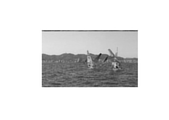
- FIG. 2 is a diagram showing an example of an RGB image.
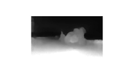
- FIG. 3 is a diagram showing an example of a depth map estimated from the RGB image of FIG. 2.
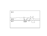
- FIG. 4 is a diagram showing an example of segmentation results divided into regions of objects detected from the RGB image of FIG. 2.
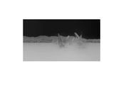
- FIG. 5 is a diagram showing an example of a depth map output by the accuracy improving device of the present embodiment.
- FIG. 6 is a flowchart showing a processing flow of the accuracy improving device of the present embodiment.
- FIG. 7 is a diagram showing an example of a depth map obtained by further performing edge retention smoothing using an RGB image as a guide.
- FIG. 8 is a diagram showing an example of the hardware configuration of the accuracy improving device.
- FIG. 1 is a block diagram showing an example of the configuration of the accuracy improving device 1 of the present embodiment.
- the accuracy improving device 1 shown in FIG. 1 includes a depth estimation unit 11, a segmentation unit 12, a painting processing unit 13, a size changing unit 14, a smoothing processing unit 15, and a post processing unit 16.
- the accuracy improving device 1 inputs an RGB image to be processed, estimates a depth map from the RGB image, divides the RGB image into regions, generates a segmentation image in which the regions are painted, and creates a segmentation image in which the regions are painted. Is used as a guide image to output a depth map with edge retention and smoothing.
- the depth estimation unit 11 inputs an RGB image, estimates the depth map, and outputs the depth map.
- the depth map is image data in which the depth of each pixel is expressed by 256 gradations of gray from 0 to 255. For example, the innermost part is 0 and the front part is 255.
- the depth map may be a gradation other than 256 gradations.
- An example of an RGB image to be input is shown in FIG. 2, and an example of a depth map estimated from the RGB image of FIG. 2 is shown in FIG.
- a method called Depth from Video in the Wild can be used.
- the accuracy improving device 1 may input a depth map estimated from an RGB image by an external device without providing the depth estimation unit 11.
- the segmentation unit 12 inputs an RGB image, detects an object in the image, and outputs a segmentation result obtained by dividing a region where the object is located in pixel units.
- the segmentation result is data in which a segment ID is assigned to each region divided for each detected object.
- the segmentation result is data to which a corresponding segment ID is assigned in pixel units.
- FIG. 4 shows an example of the segmentation result.
- the RGB image is divided into nine areas, and each area is given a segment ID of 1 to 9.
- a method called Mask R-CNN can be used.
- the accuracy improving device 1 may input the segmentation result in which the RGB image is segmented by an external device without providing the segmentation unit 12.
- the painting processing unit 13 inputs the segmentation result and the RGB image, fills each area in the segmentation result with the color of the average value of the pixel values in each area in the RGB image, and outputs the painted segmentation image.
- the average value of the pixel values in each region in the RGB image as the color to be painted separately, the difference in the color of each object in the RGB image is reflected in the edge determination.
- the edges of the contours between the regions with a large hue difference are conspicuous, and the edges of the contours between the regions with a small hue difference are not conspicuous. This makes it possible to generate a depth map with stronger object boundaries while reflecting the color information of the RGB image.
- the painting processing unit 13 fills the area not extracted as an area in the segmentation result with black. Instead of black, a color not used in other segments may be used.
- the resizing unit 14 inputs the depth map and the segmented segmentation image, changes the size of the depth map and the segmented segmentation image, and outputs the depth map and the segmentation image of the same size. do.
- the resizing unit 14 may change the segmentation image separated from the depth map to the same size as the original RGB image. Most of the depth estimation processing and segmentation processing perform processing using a reduced image of the original image in order to reduce the processing cost. If the depth map and the divided segmentation image have the same size, the processing of the resizing unit 14 is unnecessary. By estimating the reduced depth map and the segmentation result, each processing time of the depth map estimation process and the segmentation process is shortened, and as a result, the processing time of the entire system can be shortened.
- the smoothing processing unit 15 inputs the depth map and the segmented segmentation image, edge-holds and smoothes the depth map using the painted segmentation image as a guide, and outputs the edge-retaining and smoothed depth map.
- using the divided segmentation image as a guide means that when smoothing the depth map, it is processed based on the depth map information (difference in color and closeness of distance). Instead, it is processed based on the information of the segmented image that has been painted separately.
- the smoothing processing unit 15 uses the divided segmentation image as a guide image, and uses the Joint Visual Filter or the Guided Filter to perform edge retention smoothing processing on the depth map. The accuracy is improved by repeatedly performing the filtering process, but if it is performed too much, smoothing is excessively performed. Therefore, the appropriate number of times is determined based on how the edges of the contour portion stand out and the degree of smoothing inside the object.
- the post processing unit 16 inputs a depth map on which edge retention smoothing processing has been performed, applies a blur removal filter to the depth map, and outputs a depth map in which the boundary portion of the object is made clearer.
- the post processing unit 16 is provided to generate a depth map having a clear boundary portion.
- a Digital Energy Filter can be used as a blur removal filter for removing blur and haze.
- the processing by the post processing unit 16 is not essential. Even if the processing by the post processing unit 16 is not performed, the depth map with sufficiently high accuracy can be generated by the processing up to the smoothing processing unit 15.
- FIG. 5 shows an example of the output of the depth map.
- step S11 the depth estimation unit 11 estimates the depth map from the RGB image.
- the accuracy improving device 1 may input a depth map estimated by an external device.
- step S12 the segmentation unit 12 detects an object in the RGB image and divides the RGB image into a region for each detected object.
- the accuracy improving device 1 may input the segmentation result obtained by the external device.
- step S13 the painting division processing unit 13 fills each of the regions divided by the segmentation result with the color of the average value of the pixel values in each region in the RGB image.
- step S14 the size changing unit 14 changes the size of the segmentation image that is painted separately from the depth map.
- step S15 the smoothing processing unit 15 performs edge-preserving smoothing processing on the depth map using the divided segmentation image as a guide.
- step S16 the post processing unit 16 applies a blur removal filter to the depth map.
- each area may be painted with a random color, or segmentation.
- the result may be collated with the depth map and painted with a grayscale of the average value of the values indicating the depth in the depth map of each region.
- the areas not extracted as a result of segmentation are painted in black.
- the color-separating processing unit 13 may select a color for coloring each area so that the color difference between the adjacent areas becomes large.
- adjacent areas are filled with colors (complementary colors) that are opposite on the color wheel.
- the segment IDs are assigned in order from the upper left area to the side, and when the assignment is completed up to the right end, the segment ID is returned to the left end and the next line is processed. Then, the colors located opposite to each other on the color wheel are selected in order of the segment ID to fill the area.
- the painting processing unit 13 may select a color for painting each area based on the category of the object detected in the segmentation processing. For example, the painting processing unit 13 fills the background area such as the sky, the sea, and the wall with a cool color, and the area of an object (subject) such as a person or a ship with a warm color. As a result, the edge of the boundary portion between the subject and the background is emphasized, the subject and the background are separated, and it can be expected to generate a depth map in which the subject is emphasized.
- the smoothing processing unit 15 may further perform edge retention smoothing using an RGB image as a guide, in addition to the process of performing edge retention smoothing of the depth map using the segmentation image as a guide.
- Edge retention smoothing using an RGB image as a guide can be performed in the same manner as in the prior art. As a result, it is possible to generate a depth map in which the boundary portion of the object becomes clearer, but as shown in FIG. 7, the depth information inside the object also changes, so it is necessary to take this into consideration when applying.
- the accuracy improving device 1 of the present embodiment generates a segmentation image in which each of the regions is painted with a specified color based on the segmentation result of dividing the RGB image to be processed into a plurality of regions.
- a division processing unit 13 and a smoothing processing unit 15 that uses a segmentation image as a guide image and performs edge retention smoothing processing on a depth map estimated from an RGB image to be processed are provided. This makes it possible to clarify the boundaries of the object in the depth map and prevent unintended misprocessing of the depth inside the object. As a result, the accuracy of the depth map can be improved and a clear 3D image can be generated.
- the accuracy improving device 1 described above includes, for example, a central processing unit (CPU) 901, a memory 902, a storage 903, a communication device 904, an input device 905, and an output device 906, as shown in FIG.
- CPU central processing unit
- a general-purpose computer system including the above can be used.
- the accuracy improving device 1 is realized by the CPU 901 executing a predetermined program loaded on the memory 902.
- This program can be recorded on a computer-readable recording medium such as a magnetic disk, an optical disk, or a semiconductor memory, or can be distributed via a network.
Landscapes
- Engineering & Computer Science (AREA)
- Physics & Mathematics (AREA)
- General Physics & Mathematics (AREA)
- Theoretical Computer Science (AREA)
- Computer Vision & Pattern Recognition (AREA)
- Multimedia (AREA)
- Signal Processing (AREA)
- Image Analysis (AREA)
- Image Processing (AREA)
- Testing, Inspecting, Measuring Of Stereoscopic Televisions And Televisions (AREA)
Abstract
本実施形態の精度向上装置1は、処理対象のRGB画像を複数の領域に分割したセグメンテーション結果に基づき、領域のそれぞれを指定の色で塗分けたセグメンテーション画像を生成する塗分け処理部13と、セグメンテーション画像をガイド画像として用い、処理対象のRGB画像から推定されたデプスマップにエッジ保持平滑化処理を実施する平滑化処理部15を備える。
Description
本発明は、デプスマップの精度向上装置、方法、およびプログラムに関する。
一般的に、デプス推定では、RGB画像の各ピクセルのデプス値をそれぞれ推定する。デプス推定で得られたデプスマップをRGB画像と比較した場合、推定精度が低いためノイズが多く、特に各オブジェクトの境界部分のデプスが曖昧になっており、外れ値や揺らぎの除去などデプスマップの精度を向上させる後処理が必要となっている。
デプスマップを3D変換で利用する場合、RGB画像中のオブジェクトとデプスマップ中のオブジェクトのデプスの関係が精緻であるほど、よりクリアな3D画像を生成できる。
RGB画像のエッジ情報(画素値境界)をデプスに転写することにより、デプスマップにおける画素値境界を明確化する手法として、RGB画像を用いたエッジ保持平滑化が知られている。
Johannes Kopf, Michael F. Cohen, Dani Lischinski, and Matt UyttenDaele,"Joint Bilateral Upsampling"
Takuya Matsuo, Norishige Fukushima, and Yutaka Ishibashi,"Weighted Joint Bilateral Filter with Slope Depth Compensation Filter for Depth Map Refinement"
しかしながら、従来技術では、オブジェクト周辺のエッジとオブジェクト内部のエッジに区別はなく、オブジェクトの境界を明確化しようとフィルタを強くかけると、オブジェクト内部でのエッジ部分にも強くフィルタがかかるという問題があった。結果として、オブジェクト内部でのデプス情報が推定結果から大きく外れた値となり、デプスマップとしての精度を下げてしまう。
本発明は、上記に鑑みてなされたものであり、デプスマップの精度向上を実現することを目的とする。
本発明の一態様の精度向上装置は、デプスマップの精度を向上するための精度向上装置であって、処理対象の画像を複数の領域に分割したセグメンテーション結果に基づき、前記領域のそれぞれを指定の色で塗分けたセグメンテーション画像を生成する塗分け処理部と、前記セグメンテーション画像をガイド画像として用い、前記処理対象の画像から推定されたデプスマップにエッジ保持平滑化処理を実施する平滑化処理部を備える。
本発明の一態様の精度向上方法は、コンピュータが実行する精度向上方法であって、処理対象の画像を複数の領域に分割したセグメンテーション結果に基づき、前記領域のそれぞれを指定の色で塗分けたセグメンテーション画像を生成し、前記セグメンテーション画像をガイド画像として用い、前記処理対象の画像から推定されたデプスマップにエッジ保持平滑化処理を実施する。
本発明によれば、デプスマップの精度向上を実現できる。
以下、本発明の実施の形態について図面を用いて説明する。
[構成]
図1は、本実施形態の精度向上装置1の構成の一例を示すブロック図である。図1に示す精度向上装置1は、デプス推定部11、セグメンテーション部12、塗分け処理部13、サイズ変更部14、平滑化処理部15、およびポスト処理部16を備える。精度向上装置1は、処理対象のRGB画像を入力し、RGB画像からデプスマップを推定するとともに、RGB画像を領域に分割して領域を塗分けたセグメンテーション画像を生成し、塗分けされたセグメンテーション画像をガイド画像として用いてエッジ保持平滑化したデプスマップを出力する。
図1は、本実施形態の精度向上装置1の構成の一例を示すブロック図である。図1に示す精度向上装置1は、デプス推定部11、セグメンテーション部12、塗分け処理部13、サイズ変更部14、平滑化処理部15、およびポスト処理部16を備える。精度向上装置1は、処理対象のRGB画像を入力し、RGB画像からデプスマップを推定するとともに、RGB画像を領域に分割して領域を塗分けたセグメンテーション画像を生成し、塗分けされたセグメンテーション画像をガイド画像として用いてエッジ保持平滑化したデプスマップを出力する。
デプス推定部11は、RGB画像を入力してデプスマップを推定し、デプスマップを出力する。デプスマップは、各画素の奥行きを0から255のグレーの256階調で表現した画像データである。例えば、一番奥を0、手前を255とする。デプスマップは、256階調以外の階調でもよい。図2に入力するRGB画像の一例を示し、図3に図2のRGB画像から推定したデプスマップの一例を示す。デプスマップの推定には、例えば、Depth from Videos in the Wildという手法を用いることができる。なお、精度向上装置1は、デプス推定部11を備えずに、外部の装置でRGB画像から推定されたデプスマップを入力してもよい。
セグメンテーション部12は、RGB画像を入力して、画像内の物体を検出し、物体がある領域をピクセル単位で分割したセグメンテーション結果を出力する。セグメンテーション結果は、検出された物体ごとに分割された各領域にセグメントIDが付与されたデータである。例えば、セグメンテーション結果は、ピクセル単位で対応するセグメントIDが付与されたデータである。図4にセグメンテーション結果の一例を示す。図4の例では、RGB画像が9つの領域に分割されており、各領域に1から9のセグメントIDが付与されている。セグメンテーション処理には、例えば、Mask R-CNNという手法を用いることができる。なお、精度向上装置1は、セグメンテーション部12を備えずに、外部の装置でRGB画像がセグメンテーション処理されたセグメンテーション結果を入力してもよい。
塗分け処理部13は、セグメンテーション結果とRGB画像を入力し、セグメンテーション結果における各領域を、RGB画像における各領域内の画素値の平均値の色で塗りつぶし、塗分けされたセグメンテーション画像を出力する。塗分ける色としてRGB画像における各領域内の画素値の平均値を用いることで、RGB画像での各オブジェクトの色の違いがエッジ判定に反映される。色相差の大きい領域間の輪郭はエッジが際立ち、色相差の小さい領域間の輪郭はエッジが際立たない。これにより、RGB画像の色情報を反映しつつ、オブジェクト境界をより強めたデプスマップを生成できる。塗分け処理部13は、セグメンテーション結果において領域として抽出されていないエリアは黒で塗りつぶす。黒の代わりに他のセグメントで用いられていない色を用いてもよい。
サイズ変更部14は、デプスマップと塗分けされたセグメンテーション画像を入力し、デプスマップと塗分けされたセグメンテーション画像のサイズを変更して、同一のサイズのデプスマップと塗分けされたセグメンテーション画像を出力する。サイズ変更部14は、デプスマップと塗分けされたセグメンテーション画像を元のRGB画像と同じサイズに変更してよい。デプス推定処理およびセグメンテーション処理の多くは、処理コストを小さくするために、元画像を縮小した画像を用いて処理を行う。なお、デプスマップおよび塗分けされたセグメンテーション画像のサイズが同じであれば、サイズ変更部14の処理は不要である。縮小したデプスマップおよびセグメンテーション結果を推定することで、デプスマップの推定処理とセグメンテーション処理の各処理時間が短縮されるので、結果的に、システム全体での処理時間の短縮が可能となる。
平滑化処理部15は、デプスマップと塗分けされたセグメンテーション画像を入力し、塗分けされたセグメンテーション画像をガイドにデプスマップをエッジ保持平滑化し、エッジ保持平滑化したデプスマップを出力する。ここで、塗分けされたセグメンテーション画像をガイドにするとは、デプスマップに対して平滑化処理を実施するに際して、デプスマップの情報(色の違いや距離の近さ)をもとに処理するのではなく、塗分けされたセグメンテーション画像の情報をもとに処理することである。具体的には、平滑化処理部15は、塗分けされたセグメンテーション画像をガイド画像として用い、Joint Bilateral FilterまたはGuided Filterを利用して、デプスマップに対してエッジ保持平滑化処理を実施する。フィルタ処理は繰り返し実施することで精度向上するが、実施しすぎると平滑化が過度に実施される。そのため、輪郭部分のエッジの際立ち方とオブジェクト内部の平滑化の程度をもとに、適切な回数を判断する。
ポスト処理部16は、エッジ保持平滑化処理が実施されたデプスマップを入力し、デプスマップにボケ除去フィルタを適用し、オブジェクトの境界部分をよりくっきりとさせたデプスマップを出力する。平滑化処理部15で平滑化が実施されると、デプスマップではオブジェクト周辺にボケ・霞が発生する。そこで、本実施形態では、ポスト処理部16を備えて、境界部分がくっきりとしたデプスマップを生成する。ボケ・霞を除去するボケ除去フィルタとしてDetail Enhance Filterを用いることができる。なお、ポスト処理部16による処理は必須ではない。ポスト処理部16による処理をしなくても、平滑化処理部15までの処理によって十分に精度の高いデプスマップを生成できる。図5にデプスマップの出力の一例を示す。
[動作]
図6のフローチャートを参照し、本実施形態の精度向上装置1の処理の流れについて説明する。
図6のフローチャートを参照し、本実施形態の精度向上装置1の処理の流れについて説明する。
ステップS11にて、デプス推定部11は、RGB画像からデプスマップを推定する。精度向上装置1は、外部の装置で推定したデプスマップを入力してもよい。
ステップS12にて、セグメンテーション部12は、RGB画像内の物体を検出し、RGB画像を検出された物体ごとの領域に分割する。精度向上装置1は、外部の装置で求めたセグメンテーション結果を入力してもよい。
ステップS13にて、塗分け処理部13は、セグメンテーション結果で分割された領域のそれぞれを、RGB画像における各領域内の画素値の平均値の色で塗りつぶす。
ステップS14にて、サイズ変更部14は、デプスマップと塗分けされたセグメンテーション画像のサイズを変更する。
ステップS15にて、平滑化処理部15は、塗分けされたセグメンテーション画像をガイドにデプスマップにエッジ保持平滑化処理を施す。
ステップS16にて、ポスト処理部16は、デプスマップにボケ除去フィルタを適用する。
[変形例]
次に、塗分け処理とデプスマップの平滑化処理の変形例について説明する。
次に、塗分け処理とデプスマップの平滑化処理の変形例について説明する。
塗分け処理部13による、RGB画像を複数の領域に分割したセグメンテーション結果に基づいて、領域のそれぞれを指定の色で塗分ける処理では、各領域をランダムな色で塗分けてもよいし、セグメンテーション結果をデプスマップと照合し、各領域のデプスマップでのデプスを示す値の平均値のグレースケールで塗分けてもよい。このとき、セグメンテーション結果として抽出されていない領域は黒で塗分ける。
あるいは、塗分け処理部13は、隣接する領域の色の差が大きくなるように各領域を塗分ける色を選択してもよい。例えば、隣接する領域を、色相環で反対に位置する色(補色)で塗りつぶす。セグメントIDを、例えば左上の領域から横に向かって順番に付与し、右端まで付与し終えたら左端に戻って次の行を処理する。そして、色相環で反対に位置する色をセグメントID順に順番に選択して領域を塗りつぶす。
あるいは、塗分け処理部13は、セグメンテーション処理で検出された物体のカテゴリに基づいて各領域を塗分ける色を選択してもよい。例えば、塗分け処理部13は、空、海、壁などの背景の領域を寒色系の色で塗りつぶし、人、船などの物体(被写体)の領域を暖色系の色で塗りつぶす。これにより、被写体と背景の境界部分のエッジを際立たせて、被写体と背景が分離され、被写体が際立たったデプスマップの生成が期待できる。
平滑化処理部15は、セグメンテーション画像をガイドにデプスマップのエッジ保持平滑化を実施する処理に加えて、さらにRGB画像をガイドにエッジ保持平滑化を実施してもよい。RGB画像をガイドに用いたエッジ保持平滑化は従来技術と同様に実施できる。これにより、オブジェクトの境界部分がより鮮明になったデプスマップを生成できるが、図7に示すように、オブジェクト内部のデプス情報も変化するため、それを加味しての適用が必要である。
以上説明したように、本実施形態の精度向上装置1は、処理対象のRGB画像を複数の領域に分割したセグメンテーション結果に基づき、領域のそれぞれを指定の色で塗分けたセグメンテーション画像を生成する塗分け処理部13と、セグメンテーション画像をガイド画像として用い、処理対象のRGB画像から推定されたデプスマップにエッジ保持平滑化処理を実施する平滑化処理部15を備える。これにより、デプスマップにおいてオブジェクトの境界を明確化しつつ、オブジェクト内部での意図しないデプスの誤処理を防ぐことができる。その結果、デプスマップの精度向上を実現でき、クリアな3D画像を生成できる。
上記説明した精度向上装置1には、例えば、図8に示すような、中央演算処理装置(CPU)901と、メモリ902と、ストレージ903と、通信装置904と、入力装置905と、出力装置906とを備える汎用的なコンピュータシステムを用いることができる。このコンピュータシステムにおいて、CPU901がメモリ902上にロードされた所定のプログラムを実行することにより、精度向上装置1が実現される。このプログラムは磁気ディスク、光ディスク、半導体メモリ等のコンピュータ読み取り可能な記録媒体に記録することも、ネットワークを介して配信することもできる。
1…精度向上装置
11…デプス推定部
12…セグメンテーション部
13…塗分け処理部
14…サイズ変更部
15…平滑化処理部
16…ポスト処理部
11…デプス推定部
12…セグメンテーション部
13…塗分け処理部
14…サイズ変更部
15…平滑化処理部
16…ポスト処理部
Claims (7)
- デプスマップの精度を向上するための精度向上装置であって、
処理対象の画像を複数の領域に分割したセグメンテーション結果に基づき、前記領域のそれぞれを指定の色で塗分けたセグメンテーション画像を生成する塗分け処理部と、
前記セグメンテーション画像をガイド画像として用い、前記処理対象の画像から推定されたデプスマップにエッジ保持平滑化処理を実施する平滑化処理部を備える
精度向上装置。 - 請求項1に記載の精度向上装置であって、
前記塗分け処理部は、前記領域のそれぞれを
前記処理対象の画像における当該領域内の画素値の平均値で塗分ける
精度向上装置。 - 請求項1に記載の精度向上装置であって、
前記塗分け処理部は、前記領域のそれぞれを隣接する領域間で色の差が大きくなるような補色で塗分ける
精度向上装置。 - 請求項1ないし3のいずれかに記載の精度向上装置であって、
前記平滑化処理部は、さらに、前記デプスマップに前記処理対象の画像をガイド画像として用いたエッジ保持平滑化処理を実施する
精度向上装置。 - 請求項1ないし4のいずれかに記載の精度向上装置であって、
前記デプスマップと前記セグメンテーション画像の大きさを同じにするサイズ変更部を備える
精度向上装置。 - コンピュータが実行する精度向上方法であって、
処理対象の画像を複数の領域に分割したセグメンテーション結果に基づき、前記領域のそれぞれを指定の色で塗分けたセグメンテーション画像を生成し、
前記セグメンテーション画像をガイド画像として用い、前記処理対象の画像から推定されたデプスマップにエッジ保持平滑化処理を実施する
精度向上方法。 - 請求項1ないし5のいずれかに記載の精度向上装置の各部としてコンピュータを動作させるプログラム。
Priority Applications (3)
| Application Number | Priority Date | Filing Date | Title |
|---|---|---|---|
| US18/016,592 US20230281759A1 (en) | 2020-07-22 | 2020-07-22 | Depth map accuracy improvement apparatus, method, and program |
| PCT/JP2020/028444 WO2022018857A1 (ja) | 2020-07-22 | 2020-07-22 | デプスマップの精度向上装置、方法、およびプログラム |
| JP2022538554A JP7417166B2 (ja) | 2020-07-22 | 2020-07-22 | デプスマップの精度向上装置、方法、およびプログラム |
Applications Claiming Priority (1)
| Application Number | Priority Date | Filing Date | Title |
|---|---|---|---|
| PCT/JP2020/028444 WO2022018857A1 (ja) | 2020-07-22 | 2020-07-22 | デプスマップの精度向上装置、方法、およびプログラム |
Publications (1)
| Publication Number | Publication Date |
|---|---|
| WO2022018857A1 true WO2022018857A1 (ja) | 2022-01-27 |
Family
ID=79729146
Family Applications (1)
| Application Number | Title | Priority Date | Filing Date |
|---|---|---|---|
| PCT/JP2020/028444 Ceased WO2022018857A1 (ja) | 2020-07-22 | 2020-07-22 | デプスマップの精度向上装置、方法、およびプログラム |
Country Status (3)
| Country | Link |
|---|---|
| US (1) | US20230281759A1 (ja) |
| JP (1) | JP7417166B2 (ja) |
| WO (1) | WO2022018857A1 (ja) |
Citations (1)
| Publication number | Priority date | Publication date | Assignee | Title |
|---|---|---|---|---|
| JP2014038546A (ja) * | 2012-08-20 | 2014-02-27 | Nippon Soken Inc | 視差マップ生成装置および視差マップ生成装置用のプログラム |
-
2020
- 2020-07-22 US US18/016,592 patent/US20230281759A1/en not_active Abandoned
- 2020-07-22 JP JP2022538554A patent/JP7417166B2/ja active Active
- 2020-07-22 WO PCT/JP2020/028444 patent/WO2022018857A1/ja not_active Ceased
Patent Citations (1)
| Publication number | Priority date | Publication date | Assignee | Title |
|---|---|---|---|---|
| JP2014038546A (ja) * | 2012-08-20 | 2014-02-27 | Nippon Soken Inc | 視差マップ生成装置および視差マップ生成装置用のプログラム |
Non-Patent Citations (3)
| Title |
|---|
| FUKUSHIMA, NORISHIGE; ISHIBASHI, YUTAKA: "Post-filtering for Depth Images for Depth Image Based Rendering", IEICE TRANSACTIONS, vol. J94-D, no. 12, 1 December 2011 (2011-12-01), pages 1992 - 1995, XP009534181 * |
| JIAN : "Image Smoothing and Noise Reduction with Segment Bilateral Filter", IMAGE LABORATORY, vol. 23, no. 3, 10 March 2012 (2012-03-10), JP , pages 25 - 29, XP009534530, ISSN: 0915-6755 * |
| MATSUO, TAKUYA ET AL.: "Weighted Joint Bilateral Filter for Improved Depth Estimation Accuracy", THE 74TH NATIONAL CONVENTION OF THE INFORMATION PROCESSING SOCIETY OF JAPAN, 6 March 2012 (2012-03-06), JP, pages 2 - 2-244, XP009534518 * |
Also Published As
| Publication number | Publication date |
|---|---|
| JPWO2022018857A1 (ja) | 2022-01-27 |
| US20230281759A1 (en) | 2023-09-07 |
| JP7417166B2 (ja) | 2024-01-18 |
Similar Documents
| Publication | Publication Date | Title |
|---|---|---|
| US10339643B2 (en) | Algorithm and device for image processing | |
| CN108205804B (zh) | 图像处理方法、装置及电子设备 | |
| US10389936B2 (en) | Focus stacking of captured images | |
| US9042673B2 (en) | Method and apparatus for deblurring non-uniform motion blur in large scale input image based on tile unit | |
| US8396324B2 (en) | Image processing method and apparatus for correcting distortion caused by air particles as in fog | |
| JP4498671B2 (ja) | イメージコンテンツに基づいて画像の特性を改善するための方法及びシステム | |
| US9438769B1 (en) | Preserving smooth-boundaried objects of an image | |
| CN111340732B (zh) | 一种低照度视频图像增强方法及装置 | |
| US10026154B2 (en) | System and method for supporting image denoising based on neighborhood block dimensionality reduction | |
| JP2011521370A (ja) | 画像の鮮鋭度を向上させる画像処理 | |
| CN110706174A (zh) | 一种图像增强方法、终端设备及存储介质 | |
| CN112819721B (zh) | 一种图像彩色噪声降噪的方法和系统 | |
| US20130243346A1 (en) | Method and apparatus for deblurring non-uniform motion blur using multi-frame including blurred image and noise image | |
| US8144996B1 (en) | Image processing apparatus | |
| CN113763293B (zh) | 图像处理方法、装置、计算机可读存储介质与处理器 | |
| CN110390643A (zh) | 一种车牌增强方法、装置及电子设备 | |
| CN118397029B (zh) | 一种基于边缘检测的抗锯齿系统和方法 | |
| EP3086553A1 (en) | Method and apparatus for image colorization | |
| CN114140348A (zh) | 一种对比度增强方法、装置及设备 | |
| CN120339151A (zh) | 基于机器视觉的昏暗图像预处理方法、装置、设备及介质 | |
| CN113012079B (zh) | 低亮度车底图像增强方法、装置及存储介质 | |
| KR20230077854A (ko) | 단일 이미지를 이용한 특징 강화 가중치 기반의 딥러닝 다중 노출 융합 방법, 장치, 및 프로그램 | |
| CN115100070A (zh) | 一种图像的阴影去除方法 | |
| CN119991479A (zh) | 一种结合衰减通道校正的水下图像增强方法、系统及设备 | |
| JP7417166B2 (ja) | デプスマップの精度向上装置、方法、およびプログラム |
Legal Events
| Date | Code | Title | Description |
|---|---|---|---|
| 121 | Ep: the epo has been informed by wipo that ep was designated in this application |
Ref document number: 20945908 Country of ref document: EP Kind code of ref document: A1 |
|
| ENP | Entry into the national phase |
Ref document number: 2022538554 Country of ref document: JP Kind code of ref document: A |
|
| NENP | Non-entry into the national phase |
Ref country code: DE |
|
| 122 | Ep: pct application non-entry in european phase |
Ref document number: 20945908 Country of ref document: EP Kind code of ref document: A1 |