WO2022014041A1 - 伝送装置管理装置、伝送装置管理システム、伝送装置管理方法及びプログラム - Google Patents
伝送装置管理装置、伝送装置管理システム、伝送装置管理方法及びプログラム Download PDFInfo
- Publication number
- WO2022014041A1 WO2022014041A1 PCT/JP2020/027843 JP2020027843W WO2022014041A1 WO 2022014041 A1 WO2022014041 A1 WO 2022014041A1 JP 2020027843 W JP2020027843 W JP 2020027843W WO 2022014041 A1 WO2022014041 A1 WO 2022014041A1
- Authority
- WO
- WIPO (PCT)
- Prior art keywords
- transmission device
- virtual switch
- optical transmission
- management system
- path
- Prior art date
- Legal status (The legal status is an assumption and is not a legal conclusion. Google has not performed a legal analysis and makes no representation as to the accuracy of the status listed.)
- Ceased
Links
Images



Classifications
-
- H—ELECTRICITY
- H04—ELECTRIC COMMUNICATION TECHNIQUE
- H04L—TRANSMISSION OF DIGITAL INFORMATION, e.g. TELEGRAPHIC COMMUNICATION
- H04L12/00—Data switching networks
- H04L12/02—Details
- H04L12/12—Arrangements for remote connection or disconnection of substations or of equipment thereof
-
- H—ELECTRICITY
- H04—ELECTRIC COMMUNICATION TECHNIQUE
- H04J—MULTIPLEX COMMUNICATION
- H04J14/00—Optical multiplex systems
- H04J14/02—Wavelength-division multiplex systems
- H04J14/0201—Add-and-drop multiplexing
- H04J14/0202—Arrangements therefor
- H04J14/021—Reconfigurable arrangements, e.g. reconfigurable optical add/drop multiplexers [ROADM] or tunable optical add/drop multiplexers [TOADM]
Definitions
- the present invention relates to a transmission device management device, a transmission device management system, a transmission device management method, and a program.
- SDN Software Defined Networking
- SDN is a technology for centrally controlling network devices with a single piece of software.
- the SDN separates the transfer function and the control function in the network into a data plane and a control plane, respectively.
- the SDN arranges a software-defined control function in a cloud or the like on the control plane to control communication devices on the data plane.
- Non-Patent Document 1 proposes a method of abstracting an optical transmission device such as a ROADM (Reconfigurable Optical Add / Drop Multiplexer) as a virtual open flow switch (OF-ROADM) (FIG. 5).
- ROADM is a technology that efficiently operates an ultra-high-speed and large-capacity transmission network by combining a wavelength division multiplexing method and a path management technology.
- Non-Patent Document 2 proposes a method of multilayer integrated management in which an optical transmission device and a packet switch are integrated and managed (FIG. 6).
- the layer 0, 1 device and the layer 2-4 device connected to the network there may be a plurality of multi-layer paths having different performances or functions from each other.
- the performance referred to here is, for example, a delay amount, a power consumption amount, a throughput, or the like in an optical transmission device.
- a layer 0, 1 device eg, an optical transmission device such as ROADM
- receives a signal there may be two multi-layer paths as shown in FIG.
- One path is a path in which the layer 0 and 1 devices transfer the received signal to the layer 2-4 device.
- the other path is a path in which the layer 0 and 1 devices perform transfer processing only by their own device without transferring the received signal to the layer 2-4 device.
- the technique described in Non-Patent Document 1 described above manages each layer independently, so that each path is managed as an independent path. Can not do it.
- the technique described in Non-Patent Document 2 abstracts different paths as one virtual switch, so that each path is independent. It cannot be managed as an abstract path. In this way, since each path of the multilayer cannot be managed as an independent path by the conventional technology, flexible path management such as managing the path so as to guarantee the performance and function expected by the operator is performed. There was a problem that it was difficult to realize.
- an object of the present invention is to provide a transmission device management device, a transmission device management system, a transmission device management method, and a program capable of flexibly managing a multilayer path in an optical transmission device.
- One aspect of the present invention is a reception unit that receives a configuration request for a virtual switch from a higher-level management system, and a plurality of paths including transfer processing by optical transmission devices different from each other based on the configuration request received by the reception unit.
- It is a transmission device management device including a unit.
- One aspect of the present invention is a transmission device management system having a plurality of optical transmission devices and a transmission device management device, wherein the transmission device management device includes a reception unit that receives a virtual switch configuration request from a higher-level management system.
- a decision unit that determines a plurality of paths including transfer processes by the optical transmission devices that are different from each other based on the configuration request received by the reception unit, and a transfer process based on the paths determined by the determination unit.
- This is a transmission device management system including a setting unit for setting a plurality of the optical transmission devices so that a virtual switch for executing the above is configured for each path.
- One aspect of the present invention includes a reception step for receiving a virtual switch configuration request from a higher-level management system, and a plurality of paths including transfer processing by optical transmission devices different from each other based on the configuration request received in the reception step.
- One aspect of the present invention is a program for operating a computer as the above-mentioned transmission device management device.
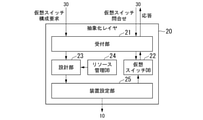
- FIG. 1 is an overall schematic view showing a basic configuration of a transmission device management system 1 according to a first embodiment of the present invention.
- the transmission device management system 1 in the present embodiment includes a communication device group 10, an abstraction layer 20, and a higher-level management system 30.
- the communication device group 10 includes an optical transmission device 11 and a layer 2-4 device 12.
- the optical transmission device 11 is a layer 0, 1 communication device (hereinafter, referred to as “layer 0, 1 device”).
- layer 0, 1 device a layer 0, 1 communication device
- the optical transmission device 11 is an optical transmission device such as ROADM.
- the layer 2-4 device 12 is a layer 2-4 communication device.
- the layer 2-4 device 12 is an OpenFlow compatible switch (OF switch) or the like.
- the abstraction layer 20 is composed of, for example, a server device or the like.
- the abstraction layer 20 is a layer for resource-pooling a communication device group 10 including an optical transmission device 11 which is a layer 0 and 1 device and a layer 2-4 device 12.
- the resource pool is a mechanism for bundling a plurality of resources of the same type (access network resources in this embodiment) such as a virtual server, storage, or a network, and managing them as one large resource.
- the abstraction layer is a means of hiding the detailed implementation of a particular function.
- the upper management system 30 includes, for example, a server device and the like.
- the higher management system 30 generates a virtual switch configuration request which is information including the configuration requirements of a virtual switch (hereinafter, referred to as “virtual switch”).
- the higher management system 30 transmits the generated virtual switch configuration request to the abstraction layer 20.
- the upper management system 30 may make an inquiry to the abstraction layer 20 regarding the virtual switch that has already been configured before generating the virtual switch configuration request. In this case, the upper management system 30 generates a virtual switch configuration request in consideration of the content of the response from the abstraction layer 20 to the inquiry.
- the abstraction layer 20 acquires a virtual switch configuration request from the upper management system 30.
- the communication device group 10 configures a virtual switch based on a configuration request from the host management system 30 by using the abstracted resource pool.
- the abstraction layer 20 provides the upper management system 30 with the configured virtual switch as a management target.
- the transmission device management system 1 manages each path as an independent path even when a plurality of multi-layer paths exist, for example. be able to.
- the transmission device management system 1 realizes flexible path management and fine-tuned performance and function management, such as managing paths so that the performance and functions expected by the operator are guaranteed. Can be done.
- FIG. 2 is a block diagram showing a functional configuration of the abstraction layer 20 of the transmission device management system 1 according to the first embodiment of the present invention.
- the abstraction layer 20 is composed of, for example, a server device or the like.
- the abstraction layer 20 includes a reception unit 21, a virtual switch database 22, a design unit 23, a resource management database 24, and a device setting unit 25.
- the “database” may be referred to as "DB”.
- the reception unit 21 receives the virtual switch configuration request transmitted from the host management system 30.
- the virtual switch configuration request includes information indicating the configuration requirements of the communication device requested by a user such as an operator.
- the virtual switch configuration request includes information on the number of ports, performance (for example, delay amount, power consumption amount, throughput, etc.), functions, and the like, which are the configuration requirements of the switch.
- the reception unit 21 outputs the acquired virtual switch configuration request to the design unit 23.
- the reception unit 21 receives inquiries regarding the already configured virtual switch sent from the host management system 30. For example, the reception unit 21 receives inquiries regarding the connection status of the virtual switch that has already been configured. The reception unit 21 acquires the information about the already configured virtual switch recorded in the virtual switch DB 22, and generates the information indicating the response to the above inquiry. The reception unit 21 transmits the generated information indicating the response to the above inquiry to the upper management system 30.
- the virtual switch DB 22 stores information about the already configured virtual switch.
- the virtual switch DB 22 returns information about the already configured virtual switch to the reception unit 21 in response to an inquiry from the reception unit 21.
- the virtual switch DB 22 includes, for example, a storage medium such as a RAM (RandomAccessMemory), a flash memory, an EEPROM (Electrically ErasableProgrammableReadOnlyMemory), and an HDD (HardDiskDrive), or any combination of these storage media. Consists of.
- the design unit 23 acquires the virtual switch configuration request output from the reception unit 21.
- the design unit 23 designs (determines) a multilayer path according to the virtual switch configuration requirements included in the acquired virtual switch configuration request. That is, the design unit 23 designs a plurality of paths including transfer processing by optical transmission devices (optical transmission device 11 and layer 2-4 device 12) different from each other.
- the design unit 23 outputs information indicating the designed path to the device setting unit 25.
- the design unit 23 When designing the path, the design unit 23 designs the path based on the information recorded in the resource management DB 24 indicating the availability of resources in the subordinate communication device group 10. Based on the designed path, the design unit 23 updates the information recorded in the resource management DB 24 indicating the availability of resources in the subordinate communication device group 10.
- the resource management DB 24 stores information indicating the availability of resources in the subordinate communication device group 10.
- the resources referred to here are, for example, wavelength resources, transfer resources, and the like.
- the resource management DB 24 is configured to include, for example, a storage medium such as RAM, flash memory, EEPROM, and HDD, or any combination of these storage media.
- the device setting unit 25 acquires information indicating a path designed by the design unit 23 from the design unit 23.
- the device setting unit 25 makes settings for the subordinate communication device group 10 according to the information indicating the acquired path. That is, the device setting unit 25 has a communication device group 10 (optical transmission device 11 and layer 2-4) so that a virtual switch that executes transfer processing based on the path designed by the design unit 23 is configured for each path. Make settings for the device 12 etc.). This configures a virtual switch.
- the device setting unit 25 records information about the configured virtual switch in the virtual switch DB 22.
- the device setting unit 25 makes settings for the subordinate communication device group 10 by using, for example, the SDN protocol.
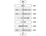
- FIG. 3 is a flowchart showing the operation of the transmission device management system 1 according to the first embodiment of the present invention.
- the abstraction layer 20 abstracts the communication device group 10 including the optical transmission device 11 which is a layer 0 and 1 device and the layer 2-4 device 12 as a resource pool in advance (step S001).
- the upper management system 30 generates a virtual switch configuration request (step S002).
- the higher management system 30 transmits the generated virtual switch configuration request to the abstraction layer 20.
- the reception unit 21 of the abstraction layer 20 receives the virtual switch configuration request transmitted from the upper management system 30 (step S003).
- the reception unit 21 outputs the acquired virtual switch configuration request to the design unit 23 of the abstraction layer 20.
- the design unit 23 acquires the virtual switch configuration request output from the reception unit 21.
- the design unit 23 confirms the virtual switch configuration requirements included in the acquired virtual switch configuration request. Further, the design unit 23 refers to the information recorded in the resource management DB 24 and confirms the availability of resources in the subordinate communication device group 10 (step S004).
- the design unit 23 designs (determines) a path based on the configuration requirements of the virtual switch and the availability of resources in the subordinate communication device group 10 (step S005).
- the design unit 23 outputs information indicating the designed path to the device setting unit 25 of the abstraction layer 20.
- the device setting unit 25 acquires information indicating the path designed by the design unit 23 from the design unit 23.
- the device setting unit 25 makes settings for the subordinate communication device group 10 according to the information indicating the acquired path (step S006). This configures a virtual switch.
- the device setting unit 25 records information about the configured virtual switch in the virtual switch DB 22 of the abstraction layer 20 (step S007). This completes the operation of the transmission device management system 1 shown in the flowchart of FIG.
- the abstraction layer 20 of the transmission device management system 1 is a communication device including an optical transmission device 11 which is a layer 0, 1 device and a layer 2-4 device 12.
- the group 10 is abstracted as a resource pool.
- the abstraction layer 20 reconfigures the resource pool as a virtual switch in response to a virtual switch configuration request from the upper management system 30.
- the abstraction layer 20 provides the configured virtual switch as a management target to the upper management system 30.
- the transmission device management system 1 can manage a plurality of layers of the multilayer as independent devices, so that the operator can perform finely tuned performance. -Function management and path management can be realized.
- the system to which the transmission device management method according to the present invention can be applied is limited to the transmission device management system 1 in which the optical transmission device 11 and the layer 2-4 device 12 are simply combined as in the first embodiment described above. is not it.
- the transmission device management method according to the present invention can be applied to, for example, an architecture in which the functions of layer 2-4 are divided into a plurality of functional parts and the plurality of functional parts are combined.
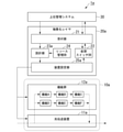
- FIG. 4 is a block diagram showing a functional configuration of the transmission device management system 1a according to the second embodiment of the present invention.
- the functional units having the same functions as the functional units included in the transmission device management system 1 according to the first embodiment are designated by the same reference numerals in FIG. 4 and the description thereof will be omitted.
- the transmission device management system 1a in the present embodiment includes a communication device group 10a, an abstraction layer 20a, and a higher management system 30.
- the communication device group 10a includes an optical transmission device 11a and a function group 12a.
- the abstraction layer 20a includes a reception unit 21, a virtual switch DB 22, a design unit 23a, a resource management DB 24, and a device setting unit 25a.
- the function group 12a has an architecture capable of combining a plurality of functional units in which the functions of layer 2-4 are made into components.
- the functional group 12a in the present embodiment has six functional parts divided into functional A to functional F.
- Each componentized functional unit has, for example, one of a bridge function, an IP (Internet Protocol) routing function, and the like.
- the functional unit included in the functional group 12a may include not only the functions belonging to layer 2-4 but also the functions belonging to layer 1 such as the coding function and the decoding function.
- the device setting unit 25a acquires information indicating the path designed by the design unit 23 from the design unit 23.
- the device setting unit 25a makes settings for the subordinate communication device group 10a according to the information indicating the acquired path. This configures a virtual switch.
- the device setting unit 25a records information about the configured virtual switch in the virtual switch DB 22.
- FIG. 4 shows a case where three paths exist as an example.
- the first path is a transfer processing path in which the optical transmission device 11a once transfers the received signal to the function group 12a, and the function group 12a performs processing related to the functions A to C for the signal. ..
- the second path is a transfer processing path in which the optical transmission device 11a once transfers the received signal to the function group 12a, and the function group 12a performs processing related to the functions D to F for the signal. ..
- the third path is a path in which the optical transmission device 11a does not transfer the received signal to the function group 12a, but performs transfer processing only by its own device.
- the three paths shown in FIG. 4 are paths having different functions and performances (for example, delay amount, power consumption amount, throughput, etc.).
- a plurality of paths having different functions and performances are designed (determined) by the design unit 23a.
- the device setting unit 25a makes settings for the subordinate communication device group 10a according to the information indicating the designed path acquired from the design unit 23a.
- the device setting unit 25 records information about a plurality of configured virtual switches in the virtual switch DB 22.
- the reception unit 21 presents information about the configured virtual switches to the host management system 30.
- the abstraction layer 20a of the transmission device management system 1a includes a communication device group 10a including an optical transmission device 11a which is a layer 0, 1 device and a function group 12a. Abstract as a resource pool. Then, the abstraction layer 20a reconfigures the resource pool as a virtual switch in response to a virtual switch configuration request from the upper management system 30. Then, the abstraction layer 20a provides the configured virtual switch as a management target to the upper management system 30.
- a path is designed by combining the componentized functional units included in the function group 12a, and the resource pool is used as a virtual switch. Can be reconstructed.
- the transmission device management system 1a can manage a plurality of layers of the multilayer as independent devices, so that the operator can manage the plurality of paths more finely. Performance / function management and path management can be realized.
- the transmission device management system has a plurality of optical transmission devices and a transmission device management device.
- the transmission device management system is the transmission device management system 1, 1a in the embodiment
- the plurality of optical transmission devices are the communication device groups 10, 10a (that is, the optical transmission devices 11, 11a, layer 2-) in the embodiment.
- the four devices 12 and the function group 12a) and the transmission device management device is a device constituting the abstraction layers 20 and 20a in the embodiment.
- the transmission device management device includes a reception unit, a determination unit, and a setting unit.
- the reception unit is the reception unit 21 in the embodiment
- the determination unit is the design unit 23, 23a in the embodiment
- the setting unit is the device setting unit 25, 25a in the embodiment.
- the reception unit receives the virtual switch configuration request from the host management system.
- the upper management system is the upper management system 30 in the embodiment.
- the determination unit determines a plurality of paths including transfer processing by different optical transmission devices based on the configuration request received by the reception unit.
- the plurality of optical transmission devices different from each other are the optical transmission devices 11 and 11a and the layer 2-4 device 12 in the embodiment.
- the setting unit sets settings for a plurality of optical transmission devices so that a virtual switch that executes transfer processing based on a plurality of paths determined by the determination unit is configured for each path.
- the determination unit may create a resource pool of a plurality of optical transmission devices.
- the setting unit may make settings for a plurality of optical transmission devices having different layers.
- the plurality of optical transmission devices having different layers may be the communication device group 10 (that is, the optical transmission device 11 and the layer 2-4 device 12) or the communication device group 10a (that is, the optical transmission device 11a and 12) in the embodiment. Function group 12a).
- the determination unit may design (determine) a path in which a plurality of functional units that have been made into parts are combined.
- the plurality of functional units are the functions A to F possessed by the functional group 12a in the embodiment.
- the decision unit may make settings for a plurality of optical transmission devices using a software defined network (SDN) protocol.
- SDN software defined network
- a part of the configuration of the transmission device management systems 1 and 1a in each of the above-described embodiments may be realized by a computer.
- a program for realizing this function may be recorded on a computer-readable recording medium, and the program recorded on the recording medium may be read by a computer system and executed.
- the term "computer system” as used herein includes hardware such as an OS and peripheral devices.
- the "computer-readable recording medium” refers to a portable medium such as a flexible disk, a magneto-optical disk, a ROM, or a CD-ROM, and a storage device such as a hard disk built in a computer system.
- a "computer-readable recording medium” is a communication line for transmitting a program via a network such as the Internet or a communication line such as a telephone line, and dynamically holds the program for a short period of time. It may also include a program that holds a program for a certain period of time, such as a volatile memory inside a computer system that is a server or a client in that case. Further, the above program may be for realizing a part of the above-mentioned functions, and may be further realized for realizing the above-mentioned functions in combination with a program already recorded in the computer system. It may be realized by using a programmable logic device such as FPGA (Field Programmable Gate Array).
- FPGA Field Programmable Gate Array
Landscapes
- Engineering & Computer Science (AREA)
- Computer Networks & Wireless Communication (AREA)
- Signal Processing (AREA)
- Data Exchanges In Wide-Area Networks (AREA)
Abstract
伝送装置管理装置は、上位管理システムからの仮想スイッチの構成要求を受け付ける受付部と、前記受付部によって受け付けられた前記構成要求に基づいて、互いに異なる光伝送装置による転送処理を含む複数のパスを決定する決定部と、前記決定部によって決定された前記パスに基づいて転送処理を実行する仮想スイッチが複数の前記パスごとにそれぞれ構成されるように複数の前記光伝送装置に対する設定を行う設定部とを備える。
Description
本発明は、伝送装置管理装置、伝送装置管理システム、伝送装置管理方法及びプログラムに関する。
昨今、ネットワークの仮想化技術の導入が進められている。例えば、アクセスネットワークへのSDN(Software Defined Networking)の適用が検討されている。SDNとは、単一のソフトウェアによりネットワーク機器を集中的に制御する技術である。SDNは、ネットワークにおける転送機能と制御機能とを、それぞれデータプレーンとコントロールプレーンとに分離する。SDNは、ソフトウェア化された制御機能をコントロールプレーン上のクラウド等に配置して、データプレーン上の通信機器を制御する。アクセスネットワークへのSDNの適用によって、アクセスネットワークの構成を柔軟に変更することが可能になり、ネットワーク運用の効率化が期待される。
また昨今、パケットスイッチ等と同様に、光伝送装置を例えばOpenFlow(以下、「OF」ともいう。)等のSDNプロトコルを用いて制御する方法が検討されている。なお、パケットスイッチとは、光パケット信号を光の状態のままパケット単位で高速に転送する技術である。例えば、非特許文献1では、ROADM(Reconfigurable Optical Add/Drop Multiplexer)等の光伝送装置を仮想的なオープンフロースイッチ(OF-ROADM)として抽象化する方法が提案されている(図5)。なお、ROADMとは、波長多重方式とパス管理の技術を組み合わせ、超高速かつ大容量の伝送ネットワークを効率的に運用する技術である。また例えば、非特許文献2では、光伝送装置とパケットスイッチとを統合して管理するマルチレイヤ統合管理の手法が提案されている(図6)。
L. Liu et al., "Field Trial of an OpenFlow-Based Unified Control Plane for Multilayer Multigranularity Optical Switching Networks," Journal of Lightwave Technology, Vol.31, No.4, pp.506-514, February 15, 2013.
S. Yamashita et al., "Extension of OpenFlow Protocol to Support Optical Transport Network, and Its Implementation," IEEE Conference on Standards for Communications and Networking (CSCN), pp.263-268, 2015.
例えば、ネットワークに接続されたレイヤ0,1装置とレイヤ2-4装置において、性能又は機能が互いに異なる、マルチレイヤの複数のパスが存在する場合がある。ここでいう性能とは、例えば光伝送装置における遅延量、電力消費量、又はスループット等である。例えば、レイヤ0,1装置(例えば、ROADM等の光伝送装置)が信号を受信した際に、図7に示されるようなマルチレイヤの2つのパスが存在する場合がある。一方のパスは、レイヤ0,1装置が、受信された信号をレイヤ2-4装置へ転送するパスである。もう一方のパスは、レイヤ0,1装置が、受信された信号をレイヤ2-4装置へ転送せずに、自装置のみで転送処理を行うパスである。
レイヤ2-4装置へ信号が転送される前者のパスの場合、例えば信号の一部を書き換える処理等を付加する等、柔軟な転送処理の実現が可能になる。しかしながら、前者のパスの場合、レイヤ2-4装置への信号の転送に伴って、性能の低下(例えば、光伝送装置における遅延量又は消費電力量の増大等)が生じる。一方、レイヤ0,1装置のみで転送処理が行われる後者のパスの場合、レイヤ2-4装置への信号の転送は行われないため、低遅延かつ省電力な転送処理を実現することができる。しかしながら、後者のパスの場合、例えば信号の一部を書き換える処理等を付加する等の柔軟な転送処理を実現することができない。
上記のようにマルチレイヤの複数のパスが存在する場合においては、前述の非特許文献1に記載の技術は、レイヤごとに独立して管理を行うことから、各々のパスを独立したパスとして管理することができない。また、上記のようにマルチレイヤの複数のパスが存在する場合においては、非特許文献2に記載の技術は、異なるパスを一つの仮想的なスイッチとして抽象化することから、各々のパスを独立したパスとして管理することができない。
このように、従来技術ではマルチレイヤの各々のパスを独立したパスとして管理することができないため、例えばオペレータが期待する性能や機能が保証されるようにパスを管理する等、柔軟なパスの管理を実現することが困難であるという課題があった。
このように、従来技術ではマルチレイヤの各々のパスを独立したパスとして管理することができないため、例えばオペレータが期待する性能や機能が保証されるようにパスを管理する等、柔軟なパスの管理を実現することが困難であるという課題があった。
上記事情に鑑み、本発明は、光伝送装置におけるマルチレイヤのパスを柔軟に管理することができる伝送装置管理装置、伝送装置管理システム、伝送装置管理方法及びプログラムを提供することを目的とする。
本発明の一態様は、上位管理システムからの仮想スイッチの構成要求を受け付ける受付部と、前記受付部によって受け付けられた前記構成要求に基づいて、互いに異なる光伝送装置による転送処理を含む複数のパスを決定する決定部と、前記決定部によって決定された前記パスに基づいて転送処理を実行する仮想スイッチが前記パスごとに構成されるように、複数の前記光伝送装置に対して設定を行う設定部と、を備える伝送装置管理装置である。
本発明の一態様は、複数の光伝送装置と伝送装置管理装置とを有する伝送装置管理システムであって、前記伝送装置管理装置は、上位管理システムからの仮想スイッチの構成要求を受け付ける受付部と、前記受付部によって受け付けられた前記構成要求に基づいて、互いに異なる前記光伝送装置による転送処理を含む複数のパスを決定する決定部と、前記決定部によって決定された前記パスに基づいて転送処理を実行する仮想スイッチが前記パスごとに構成されるように、複数の前記光伝送装置に対して設定を行う設定部と、を備える伝送装置管理システムである。
本発明の一態様は、上位管理システムからの仮想スイッチの構成要求を受け付ける受付ステップと、前記受付ステップにおいて受け付けられた前記構成要求に基づいて、互いに異なる光伝送装置による転送処理を含む複数のパスを決定する決定ステップと、前記決定ステップにおいて決定された前記パスに基づいて転送処理を実行する仮想スイッチが前記パスごとに構成されるように、複数の前記光伝送装置に対して設定を行う設定ステップと、を有する伝送装置管理方法である。
本発明の一態様は、上記の伝送装置管理装置としてコンピュータを機能させるためのプログラムである。
本発明により、光伝送装置におけるマルチレイヤのパスを柔軟に管理することができる。
以下、図面を参照しながら本発明の実施形態を詳細に説明する。
(第1の実施形態)
以下、本発明の第1の実施形態について説明する。
以下、本発明の第1の実施形態について説明する。
[伝送装置管理システムの基本構成]
以下、本実施形態における伝送装置管理システム1の基本構成について説明する。
図1は、本発明の第1の実施形態における伝送装置管理システム1の基本構成を示す全体概略図である。図1に示されるように、本実施形態における伝送装置管理システム1は、通信装置群10と、抽象化レイヤ20と、上位管理システム30とを含んで構成される。
以下、本実施形態における伝送装置管理システム1の基本構成について説明する。
図1は、本発明の第1の実施形態における伝送装置管理システム1の基本構成を示す全体概略図である。図1に示されるように、本実施形態における伝送装置管理システム1は、通信装置群10と、抽象化レイヤ20と、上位管理システム30とを含んで構成される。
通信装置群10は、光伝送装置11と、レイヤ2-4装置12とを含んで構成される。
光伝送装置11は、レイヤ0,1の通信装置(以下、「レイヤ0,1装置」という。)である。例えば光伝送装置11は、ROADM等の光伝送装置である。
レイヤ2-4装置12は、レイヤ2-4の通信装置である。例えばレイヤ2-4装置12は、OpenFlow対応のスイッチ(OFスイッチ)等である。
光伝送装置11は、レイヤ0,1の通信装置(以下、「レイヤ0,1装置」という。)である。例えば光伝送装置11は、ROADM等の光伝送装置である。
レイヤ2-4装置12は、レイヤ2-4の通信装置である。例えばレイヤ2-4装置12は、OpenFlow対応のスイッチ(OFスイッチ)等である。
抽象化レイヤ20は、例えばサーバ装置等によって構成される。抽象化レイヤ20は、レイヤ0,1装置である光伝送装置11とレイヤ2-4装置12とを含む通信装置群10をリソースプール化するレイヤである。なお、リソースプールとは、例えば仮想サーバ、ストレージ、又はネットワーク等の同一種類の複数のリソース(本実施形態においてはアクセスネットワークのリソース)を束ねて、1つの大きなリソースとして管理する仕組みである。また、抽象化レイヤとは、特定の機能の詳細な実装を隠す手段である。
上位管理システム30は、例えばサーバ装置等を含んで構成される。上位管理システム30は、仮想的なスイッチ(以下、「仮想スイッチ」という。)の構成要件を含む情報である仮想スイッチ構成要求を生成する。上位管理システム30は、生成された仮想スイッチ構成要求を抽象化レイヤ20へ送信する。
なお、上位管理システム30は、仮想スイッチ構成要求を生成する前に、抽象化レイヤ20に対して、既に構成されている仮想スイッチに関する問合せを行ってもよい。この場合、上位管理システム30は、当該問い合わせに対する抽象化レイヤ20からの応答の内容を考慮して、仮想スイッチ構成要求を生成する。
抽象化レイヤ20は、上位管理システム30から仮想スイッチの構成要求を取得する。通信装置群10が抽象化されたリソースプールを用いて、上位管理システム30からの構成要求に基づく仮想スイッチを構成する。抽象化レイヤ20は、上位管理システム30に対して、構成された仮想スイッチを管理対象として提供する。
このような構成により、本発明の第1の実施形態における伝送装置管理システム1は、例えばマルチレイヤの複数のパスが存在するような場合であっても、各々のパスを独立したパスとして管理することができる。これにより、伝送装置管理システム1は、例えばオペレータが期待する性能や機能が保証されるようにパスを管理する等、柔軟なパスの管理、及び、きめ細やかな性能及び機能の管理を実現することができる。
[抽象化レイヤの構成]
以下、抽象化レイヤ20の機能構成の一例について説明する。
図2は、本発明の第1の実施形態における伝送装置管理システム1の抽象化レイヤ20の機能構成を示すブロック図である。前述の通り、抽象化レイヤ20は、例えばサーバ装置等によって構成される。
以下、抽象化レイヤ20の機能構成の一例について説明する。
図2は、本発明の第1の実施形態における伝送装置管理システム1の抽象化レイヤ20の機能構成を示すブロック図である。前述の通り、抽象化レイヤ20は、例えばサーバ装置等によって構成される。
図2に示されるように、抽象化レイヤ20は、受付部21と、仮想スイッチデータベース22と、設計部23と、リソース管理データベース24と、装置設定部25とを含んで構成される。以下、「データベース」を「DB」と記載することがある。
受付部21は、上位管理システム30から送信された仮想スイッチ構成要求を受け付ける。仮想スイッチ構成要求には、オペレータ等のユーザが要求する通信装置の構成要件を示す情報が含まれる。例えば、仮想スイッチ構成要求には、スイッチの構成要件である、ポート数、性能(例えば、遅延量、消費電力量、又はスループット等)、及び機能等に関する情報が含まれる。受付部21は、取得した仮想スイッチ構成要求を設計部23へ出力する。
また、受付部21は、上位管理システム30から送信された、既に構成された仮想スイッチに関する問い合わせを受け付ける。例えば受付部21は、既に構成された仮想スイッチの接続状況等に関する問い合わせを受け付ける。受付部21は、仮想スイッチDB22に記録された、既に構成された仮想スイッチに関する情報を取得し、上記の問い合わせに対する応答を示す情報を生成する。受付部21は、生成された上記の問い合わせに対する応答を示す情報を上位管理システム30へ送信する。
仮想スイッチDB22は、既に構成された仮想スイッチに関する情報を記憶する。仮想スイッチDB22は、受付部21からの問い合わせに応じて、既に構成された仮想スイッチに関する情報を受付部21へ返送する。仮想スイッチDB22は、例えば、RAM(Random Access Memory)、フラッシュメモリ、EEPROM(Electrically Erasable Programmable Read Only Memory)、及びHDD(Hard Disk Drive)等の記憶媒体、又はこれらの記憶媒体の任意の組み合わせを含んで構成される。
設計部23は、受付部21から出力された、仮想スイッチ構成要求を取得する。設計部23は、取得された仮想スイッチ構成要求に含まれる、仮想スイッチの構成要件に従って、マルチレイヤのパスを設計(決定)する。すなわち、設計部23は、互いに異なる光伝送装置(光伝送装置11及びレイヤ2-4装置12)による転送処理を含む複数のパスを設計する。設計部23は、設計されたパスを示す情報を装置設定部25へ出力する。
設計部23は、パスを設計する際に、リソース管理DB24に記録された、配下の通信装置群10におけるリソースの空き状況を示す情報に基づいてパスを設計する。設計部23は、設計されたパスに基づいて、リソース管理DB24に記録された、配下の通信装置群10におけるリソースの空き状況を示す情報を更新する。
リソース管理DB24は、配下の通信装置群10におけるリソースの空き状況を示す情報を記憶する。ここでいうリソースとは、例えば、波長リソース及び転送リソース等である。リソース管理DB24は、例えば、RAM、フラッシュメモリ、EEPROM、及びHDD等の記憶媒体、又はこれらの記憶媒体の任意の組み合わせを含んで構成される。
装置設定部25は、設計部23によって設計されたパスを示す情報を、当該設計部23から取得する。装置設定部25は、取得されたパスを示す情報に従って、配下の通信装置群10に対する設定を行う。すなわち、装置設定部25は、設計部23によって設計されたパスに基づいて転送処理を実行する仮想スイッチがパスごとに構成されるように、通信装置群10(光伝送装置11及びレイヤ2-4装置12等)に対して設定を行う。これにより、仮想スイッチが構成される。装置設定部25は、構成された仮想スイッチに関する情報を仮想スイッチDB22に記録する。
なお、装置設定部25は、例えばSDNプロトコルを用いて、配下の通信装置群10に対する設定を行う。
なお、装置設定部25は、例えばSDNプロトコルを用いて、配下の通信装置群10に対する設定を行う。
[伝送装置管理システムの動作]
以下、伝送装置管理システム1の動作の一例について説明する。
図3は、本発明の第1の実施形態における伝送装置管理システム1の動作を示すフローチャートである。
以下、伝送装置管理システム1の動作の一例について説明する。
図3は、本発明の第1の実施形態における伝送装置管理システム1の動作を示すフローチャートである。
抽象化レイヤ20は、レイヤ0,1装置である光伝送装置11とレイヤ2-4装置12とを含む通信装置群10を、予めリソースプールとして抽象化する(ステップS001)。
上位管理システム30は、仮想スイッチ構成要求を生成する(ステップS002)。上位管理システム30は、生成された仮想スイッチ構成要求を抽象化レイヤ20へ送信する。
抽象化レイヤ20の受付部21は、上位管理システム30から送信された仮想スイッチ構成要求を受け付ける(ステップS003)。受付部21は、取得した仮想スイッチ構成要求を、抽象化レイヤ20の設計部23へ出力する。
設計部23は、受付部21から出力された、仮想スイッチ構成要求を取得する。設計部23は、取得された仮想スイッチ構成要求に含まれる、仮想スイッチの構成要件を確認する。また、設計部23は、リソース管理DB24に記録された情報を参照し、配下の通信装置群10におけるリソースの空き状況を確認する(ステップS004)。
設計部23は、仮想スイッチの構成要件と、配下の通信装置群10におけるリソースの空き状況とに基づいて、パスを設計(決定)する(ステップS005)。設計部23は、設計されたパスを示す情報を、抽象化レイヤ20の装置設定部25へ出力する。
装置設定部25は、設計部23によって設計されたパスを示す情報を、当該設計部23から取得する。装置設定部25は、取得されたパスを示す情報に従って、配下の通信装置群10に対する設定を行う(ステップS006)。これにより、仮想スイッチが構成される。
装置設定部25は、構成された仮想スイッチに関する情報を抽象化レイヤ20の仮想スイッチDB22に記録する(ステップS007)。
以上で、図3のフローチャートが示す伝送装置管理システム1の動作が終了する。
以上で、図3のフローチャートが示す伝送装置管理システム1の動作が終了する。
以上説明したように、本発明の第1の実施形態における伝送装置管理システム1の抽象化レイヤ20は、レイヤ0,1装置である光伝送装置11とレイヤ2-4装置12とを含む通信装置群10をリソースプールとして抽象化する。そして、抽象化レイヤ20は、上位管理システム30からの仮想スイッチの構成要求に応じて上記リソースプールを仮想スイッチとして再構成する。そして、抽象化レイヤ20は、上位管理システム30へ、構成された仮想スイッチを管理対象として提供する。
このような構成を備えることにより、本発明の第1の実施形態における伝送装置管理システム1は、マルチレイヤの複数のパスをそれぞれ独立な装置として管理することができるため、オペレータによるきめ細やかな性能・機能管理、及びパス管理を実現することができる。
(第2の実施形態)
本発明による伝送装置管理方法を適用可能なシステムは、前述の第1の実施形態のように光伝送装置11とレイヤ2-4装置12とが単に組み合わされた伝送装置管理システム1に限られるものではない。本発明による伝送装置管理方法は、例えば、レイヤ2-4の機能が複数の機能部に部品化され、複数の機能部が組み合わされるようなアーキテクチャに対しても適用可能である。
本発明による伝送装置管理方法を適用可能なシステムは、前述の第1の実施形態のように光伝送装置11とレイヤ2-4装置12とが単に組み合わされた伝送装置管理システム1に限られるものではない。本発明による伝送装置管理方法は、例えば、レイヤ2-4の機能が複数の機能部に部品化され、複数の機能部が組み合わされるようなアーキテクチャに対しても適用可能である。
図4は、本発明の第2の実施形態における伝送装置管理システム1aの機能構成を示すブロック図である。なお、前述の第1の実施形態における伝送装置管理システム1が備える機能部と同様の機能を有する機能部については、図4において同一の符号を付し説明を省略する。
図4に示されるように、本実施形態における伝送装置管理システム1aは、通信装置群10aと、抽象化レイヤ20aと、上位管理システム30とを含んで構成される。
通信装置群10aは、光伝送装置11aと、機能群12aとを含んで構成される。
抽象化レイヤ20aは、受付部21と、仮想スイッチDB22と、設計部23aと、リソース管理DB24と、装置設定部25aとを含んで構成される。
通信装置群10aは、光伝送装置11aと、機能群12aとを含んで構成される。
抽象化レイヤ20aは、受付部21と、仮想スイッチDB22と、設計部23aと、リソース管理DB24と、装置設定部25aとを含んで構成される。
機能群12aは、レイヤ2-4の機能が部品化された複数の機能部を組み合わせ可能なアーキテクチャを有する。例えば、本実施形態における機能群12aは、図4に示されるように、機能A~機能Fに部品化された6つの機能部を有する。部品化された各々の機能部は、例えば、ブリッジ機能、IP(Internet Protocol)ルーティング機能等のうち1つの機能をそれぞれ有する。
なお、機能群12aに含まれる機能部には、レイヤ2-4に属する機能だけでなく、例えば符号化機能及び復号機能等のレイヤ1に属する機能が含まれていてもよい。
なお、機能群12aに含まれる機能部には、レイヤ2-4に属する機能だけでなく、例えば符号化機能及び復号機能等のレイヤ1に属する機能が含まれていてもよい。
装置設定部25aは、設計部23によって設計されたパスを示す情報を、当該設計部23から取得する。装置設定部25aは、取得されたパスを示す情報に従って、配下の通信装置群10aに対する設定を行う。これにより、仮想スイッチが構成される。装置設定部25aは、構成された仮想スイッチに関する情報を仮想スイッチDB22に記録する。
図4は、一例として、3つのパスが存在する場合を示している。1つ目のパスは、光伝送装置11aが、受信された信号を機能群12aへ一旦転送し、機能群12aによって当該信号に対し機能A~機能Cに関する処理が行われる転送処理のパスである。2つ目のパスは、光伝送装置11aが、受信された信号を機能群12aへ一旦転送し、機能群12aによって当該信号に対し機能D~機能Fに関する処理が行われる転送処理のパスである。3つ目のパスは、光伝送装置11aが、受信された信号を機能群12aへ転送せずに、自装置のみで転送処理を行うパスである。
図4に示される3つのパスは、機能及び性能(例えば、遅延量、消費電力量、又はスループット等)が互いに異なるパスである。これらの機能及び性能が互いに異なる複数のパスは、設計部23aによって設計(決定)される。装置設定部25aは、設計部23aから取得される上記設計されたパスを示す情報に従って、配下の通信装置群10aに対する設定を行う。
これにより、それぞれのパスに対応する仮想スイッチが構成される。装置設定部25は、構成された複数の仮想スイッチに関する情報を仮想スイッチDB22に記録する。また、受付部21は、構成された複数の仮想スイッチに関する情報を上位管理システム30へ提示する。
以上説明したように、本発明の第2の実施形態における伝送装置管理システム1aの抽象化レイヤ20aは、レイヤ0,1装置である光伝送装置11aと機能群12aとを含む通信装置群10aをリソースプールとして抽象化する。そして、抽象化レイヤ20aは、上位管理システム30からの仮想スイッチの構成要求に応じて上記リソースプールを仮想スイッチとして再構成する。そして、抽象化レイヤ20aは、上位管理システム30へ、構成された仮想スイッチを管理対象として提供する。
また、本発明の第2の実施形態における伝送装置管理システム1aの抽象化レイヤ20aは、機能群12aに含まれる部品化された機能部を組み合わせてパスを設計し、上記リソースプールを仮想スイッチとして再構成することができる。
このような構成を備えることにより、本発明の第2の実施形態における伝送装置管理システム1aは、マルチレイヤの複数のパスをそれぞれ独立な装置として管理することができるため、オペレータによる更にきめ細やかな性能・機能管理、及びパス管理を実現することができる。
上述した各実施形態によれば、伝送装置管理システムは、複数の光伝送装置と伝送装置管理装置とを有する。例えば、伝送装置管理システムは、実施形態における伝送装置管理システム1、1aであり、複数の光伝送装置は、実施形態における通信装置群10、10a(すなわち、光伝送装置11、11a、レイヤ2-4装置12、機能群12a)であり、伝送装置管理装置は、実施形態における抽象化レイヤ20、20aを構成する装置である。
伝送装置管理装置は、受付部と、決定部と、設定部とを備える。例えば、受付部は、実施形態における受付部21であり、決定部は、実施形態における設計部23、23aであり、設定部は、実施形態における装置設定部25、25aである。
受付部は、上位管理システムからの仮想スイッチの構成要求を受け付ける。例えば、上位管理システムは、実施形態における上位管理システム30である。決定部は、受付部によって受け付けられた構成要求に基づいて、互いに異なる光伝送装置による転送処理を含む複数のパスを決定する。例えば、互いに異なる複数の光伝送装置は、実施形態における光伝送装置11、11a、及びレイヤ2-4装置12である。設定部は、決定部によって決定された複数のパスに基づいて転送処理を実行する仮想スイッチがパスごとに構成されるように、複数の光伝送装置に対する設定を行う。
なお、決定部は、複数の光伝送装置をリソースプール化してもよい。
なお、設定部は、互いにレイヤが異なる複数の光伝送装置に対して設定を行ってもよい。例えば、互いにレイヤが異なる複数の光伝送装置は、実施形態における通信装置群10(すなわち、光伝送装置11及びレイヤ2-4装置12)、又は、通信装置群10a(すなわち、光伝送装置11a及び機能群12a)である。
なお、設定部は、互いにレイヤが異なる複数の光伝送装置に対して設定を行ってもよい。例えば、互いにレイヤが異なる複数の光伝送装置は、実施形態における通信装置群10(すなわち、光伝送装置11及びレイヤ2-4装置12)、又は、通信装置群10a(すなわち、光伝送装置11a及び機能群12a)である。
なお、決定部は、部品化された複数の機能部が組み合わされたパスを設計(決定)してもよい。例えば、複数の機能部は、実施形態における機能群12aが有する機能A~機能Fである。
なお、決定部は、ソフトウェア・デファインド・ネットワーク(SDN)プロトコルを用いて複数の光伝送装置に対する設定を行ってもよい。
なお、決定部は、ソフトウェア・デファインド・ネットワーク(SDN)プロトコルを用いて複数の光伝送装置に対する設定を行ってもよい。
上述した各実施形態における伝送装置管理システム1、1aの構成の一部をコンピュータで実現するようにしてもよい。その場合、この機能を実現するためのプログラムをコンピュータ読み取り可能な記録媒体に記録して、この記録媒体に記録されたプログラムをコンピュータシステムに読み込ませ、実行することによって実現してもよい。なお、ここでいう「コンピュータシステム」とは、OSや周辺機器等のハードウェアを含むものとする。また、「コンピュータ読み取り可能な記録媒体」とは、フレキシブルディスク、光磁気ディスク、ROM、CD-ROM等の可搬媒体、コンピュータシステムに内蔵されるハードディスク等の記憶装置のことをいう。さらに「コンピュータ読み取り可能な記録媒体」とは、インターネット等のネットワークや電話回線等の通信回線を介してプログラムを送信する場合の通信線のように、短時間の間、動的にプログラムを保持するもの、その場合のサーバやクライアントとなるコンピュータシステム内部の揮発性メモリのように、一定時間プログラムを保持しているものも含んでもよい。また上記プログラムは、前述した機能の一部を実現するためのものであってもよく、さらに前述した機能をコンピュータシステムにすでに記録されているプログラムとの組み合わせで実現できるものであってもよく、FPGA(Field Programmable Gate Array)等のプログラマブルロジックデバイスを用いて実現されるものであってもよい。
以上、この発明の実施形態について図面を参照して詳述してきたが、具体的な構成はこの実施形態に限られるものではなく、この発明の要旨を逸脱しない範囲の設計等も含まれる。
1、1a…伝送装置管理システム、10、10a…通信装置群、11、11a…光伝送装置、12…レイヤ2-4装置、12a…機能群、20、20a…抽象化レイヤ、21…受付部、22…仮想スイッチDB、23、23a…設計部、24…リソース管理DB、25、25a…装置設定部、30…上位管理システム
Claims (8)
- 上位管理システムからの仮想スイッチの構成要求を受け付ける受付部と、
前記受付部によって受け付けられた前記構成要求に基づいて、互いに異なる光伝送装置による転送処理を含む複数のパスを決定する決定部と、
前記決定部によって決定された前記パスに基づいて転送処理を実行する仮想スイッチが前記パスごとに構成されるように、複数の前記光伝送装置に対して設定を行う設定部と、
を備える伝送装置管理装置。 - 前記決定部は、複数の前記光伝送装置をリソースプール化する
請求項1に記載の伝送装置管理装置。 - 前記設定部は、互いにレイヤが異なる複数の前記光伝送装置に対して設定を行う
請求項1又は2に記載の伝送装置管理装置。 - 前記決定部は、部品化された複数の機能部が組み合わされたパスを決定する
請求項1から3のうちいずれか一項に記載の伝送装置管理装置。 - 前記決定部は、ソフトウェア・デファインド・ネットワークプロトコルを用いて複数の前記光伝送装置に対する設定を行う
請求項1から4のうちいずれか一項に記載の伝送装置管理装置。 - 複数の光伝送装置と伝送装置管理装置とを有する伝送装置管理システムであって、
前記伝送装置管理装置は、
上位管理システムからの仮想スイッチの構成要求を受け付ける受付部と、
前記受付部によって受け付けられた前記構成要求に基づいて、互いに異なる前記光伝送装置による転送処理を含む複数のパスを決定する決定部と、
前記決定部によって決定された前記パスに基づいて転送処理を実行する仮想スイッチが前記パスごとに構成されるように、複数の前記光伝送装置に対して設定を行う設定部と、
を備える
伝送装置管理システム。 - 上位管理システムからの仮想スイッチの構成要求を受け付ける受付ステップと、
前記受付ステップにおいて受け付けられた前記構成要求に基づいて、互いに異なる光伝送装置による転送処理を含む複数のパスを決定する決定ステップと、
前記決定ステップにおいて決定された前記パスに基づいて転送処理を実行する仮想スイッチが前記パスごとに構成されるように、複数の前記光伝送装置に対して設定を行う設定ステップと、
を有する伝送装置管理方法。 - 請求項1から5のうちいずれか一項に記載の伝送装置管理装置としてコンピュータを機能させるためのプログラム。
Priority Applications (3)
| Application Number | Priority Date | Filing Date | Title |
|---|---|---|---|
| JP2022536095A JPWO2022014041A1 (ja) | 2020-07-17 | 2020-07-17 | |
| PCT/JP2020/027843 WO2022014041A1 (ja) | 2020-07-17 | 2020-07-17 | 伝送装置管理装置、伝送装置管理システム、伝送装置管理方法及びプログラム |
| US18/015,849 US12212405B2 (en) | 2020-07-17 | 2020-07-17 | Transmission device management device, transmission device management system, transmission device management method and program |
Applications Claiming Priority (1)
| Application Number | Priority Date | Filing Date | Title |
|---|---|---|---|
| PCT/JP2020/027843 WO2022014041A1 (ja) | 2020-07-17 | 2020-07-17 | 伝送装置管理装置、伝送装置管理システム、伝送装置管理方法及びプログラム |
Publications (1)
| Publication Number | Publication Date |
|---|---|
| WO2022014041A1 true WO2022014041A1 (ja) | 2022-01-20 |
Family
ID=79554579
Family Applications (1)
| Application Number | Title | Priority Date | Filing Date |
|---|---|---|---|
| PCT/JP2020/027843 Ceased WO2022014041A1 (ja) | 2020-07-17 | 2020-07-17 | 伝送装置管理装置、伝送装置管理システム、伝送装置管理方法及びプログラム |
Country Status (3)
| Country | Link |
|---|---|
| US (1) | US12212405B2 (ja) |
| JP (1) | JPWO2022014041A1 (ja) |
| WO (1) | WO2022014041A1 (ja) |
Citations (3)
| Publication number | Priority date | Publication date | Assignee | Title |
|---|---|---|---|---|
| US20150029846A1 (en) * | 2013-07-24 | 2015-01-29 | Infinera Corp. | Use of Switching for Optimizing Transport Costs for Bandwidth Services |
| JP2017143344A (ja) * | 2016-02-08 | 2017-08-17 | 富士通株式会社 | パケット伝送装置,制御装置,及びパケット伝送制御方法 |
| US20180220210A1 (en) * | 2017-02-02 | 2018-08-02 | Infinera Corporation | Multi-layer mechanisms to optimize optical transport network margin allocation |
Family Cites Families (4)
| Publication number | Priority date | Publication date | Assignee | Title |
|---|---|---|---|---|
| US8929366B2 (en) * | 2011-06-27 | 2015-01-06 | Infinera Corporation | Method and apparatus for transporting packets with specific traffic flows having strict packet ordering requirements over a network using multipath techniques |
| US10263848B2 (en) * | 2013-03-20 | 2019-04-16 | Wolting Holding B.V. | Compiler for and method for software defined networks |
| US9686176B2 (en) * | 2014-12-19 | 2017-06-20 | Ciena Corporation | Constrained and viable path computation systems and methods |
| US9780909B2 (en) * | 2014-12-29 | 2017-10-03 | Juniper Networks, Inc. | Network topology optimization with feasible optical paths |
-
2020
- 2020-07-17 JP JP2022536095A patent/JPWO2022014041A1/ja active Pending
- 2020-07-17 US US18/015,849 patent/US12212405B2/en active Active
- 2020-07-17 WO PCT/JP2020/027843 patent/WO2022014041A1/ja not_active Ceased
Patent Citations (3)
| Publication number | Priority date | Publication date | Assignee | Title |
|---|---|---|---|---|
| US20150029846A1 (en) * | 2013-07-24 | 2015-01-29 | Infinera Corp. | Use of Switching for Optimizing Transport Costs for Bandwidth Services |
| JP2017143344A (ja) * | 2016-02-08 | 2017-08-17 | 富士通株式会社 | パケット伝送装置,制御装置,及びパケット伝送制御方法 |
| US20180220210A1 (en) * | 2017-02-02 | 2018-08-02 | Infinera Corporation | Multi-layer mechanisms to optimize optical transport network margin allocation |
Non-Patent Citations (1)
| Title |
|---|
| YAMADA, AKIKO: "A study on energy efficient routing algorithms as SDN application", IEICE TECHNICAL REPORT, vol. 112, no. 288, 8 November 2012 (2012-11-08), pages 41 - 46, XP009534025 * |
Also Published As
| Publication number | Publication date |
|---|---|
| US20230261778A1 (en) | 2023-08-17 |
| US12212405B2 (en) | 2025-01-28 |
| JPWO2022014041A1 (ja) | 2022-01-20 |
Similar Documents
| Publication | Publication Date | Title |
|---|---|---|
| TWI222288B (en) | End node partitioning using virtualization | |
| KR100927748B1 (ko) | 가상 인클로저를 통한 스토리지 영역 네트워크 내의스토리지 가상화 구현 방법 및 장치 | |
| US7599397B2 (en) | Obtaining multiple port addresses by a fibre channel switch from a network fabric | |
| US20020107962A1 (en) | Single chassis network endpoint system with network processor for load balancing | |
| US20020105972A1 (en) | Interprocess communications within a network node using switch fabric | |
| US20030236919A1 (en) | Network connected computing system | |
| US20020107990A1 (en) | Network connected computing system including network switch | |
| US20020116452A1 (en) | Network connected computing system including storage system | |
| US20020107989A1 (en) | Network endpoint system with accelerated data path | |
| US20030236861A1 (en) | Network content delivery system with peer to peer processing components | |
| CN106027428B (zh) | 动态资源管理方法 | |
| CN105659563A (zh) | 用于软件定义的网络感知数据复制的系统和方法 | |
| US20020107971A1 (en) | Network transport accelerator | |
| JP2005506726A (ja) | 処理システムにおける仮想ネットワークシステムと方法 | |
| JP2004524598A (ja) | ネットワークアプリケーション装置のためのフロースケジューリング及びアーキテクチャ | |
| US7881325B2 (en) | Load balancing technique implemented in a storage area network | |
| US9871735B2 (en) | Packet I/O support for a logical switch router architecture | |
| JP2024500373A (ja) | 出版-購読型システムにおける鍵ローテーション | |
| WO2023016248A1 (zh) | 数据中心的云网络和运营商网络互通的方法和通信装置 | |
| JP2024512302A (ja) | 統合されていないコンピュータシステムにおけるジョブターゲットエイリアシング | |
| Battestilli et al. | EnLIGHTened computing: An architecture for co-allocating network, compute, and other grid resources for high-end applications | |
| DeCusatis et al. | Dynamic, software-defined service provider network infrastructure and cloud drivers for SDN adoption | |
| US7769023B2 (en) | Fibre channel traffic redirect scheme using access control lists | |
| CN117076051A (zh) | 一种容器中运行虚拟机的网络实现方法、系统、设备及介质 | |
| US20100250775A1 (en) | Introducing cascaded intelligent services in a san environment |
Legal Events
| Date | Code | Title | Description |
|---|---|---|---|
| ENP | Entry into the national phase |
Ref document number: 2022536095 Country of ref document: JP Kind code of ref document: A |
|
| NENP | Non-entry into the national phase |
Ref country code: DE |
|
| 122 | Ep: pct application non-entry in european phase |
Ref document number: 20944961 Country of ref document: EP Kind code of ref document: A1 |