WO2022009624A1 - 地図処理システム及び地図処理プログラム - Google Patents
地図処理システム及び地図処理プログラム Download PDFInfo
- Publication number
- WO2022009624A1 WO2022009624A1 PCT/JP2021/022688 JP2021022688W WO2022009624A1 WO 2022009624 A1 WO2022009624 A1 WO 2022009624A1 JP 2021022688 W JP2021022688 W JP 2021022688W WO 2022009624 A1 WO2022009624 A1 WO 2022009624A1
- Authority
- WO
- WIPO (PCT)
- Prior art keywords
- map
- skeleton
- input
- data
- unit
- Prior art date
- Legal status (The legal status is an assumption and is not a legal conclusion. Google has not performed a legal analysis and makes no representation as to the accuracy of the status listed.)
- Ceased
Links
Images


Classifications
-
- G—PHYSICS
- G01—MEASURING; TESTING
- G01C—MEASURING DISTANCES, LEVELS OR BEARINGS; SURVEYING; NAVIGATION; GYROSCOPIC INSTRUMENTS; PHOTOGRAMMETRY OR VIDEOGRAMMETRY
- G01C21/00—Navigation; Navigational instruments not provided for in groups G01C1/00 - G01C19/00
- G01C21/38—Electronic maps specially adapted for navigation; Updating thereof
- G01C21/3804—Creation or updating of map data
- G01C21/3807—Creation or updating of map data characterised by the type of data
- G01C21/3815—Road data
- G01C21/3819—Road shape data, e.g. outline of a route
-
- G—PHYSICS
- G01—MEASURING; TESTING
- G01C—MEASURING DISTANCES, LEVELS OR BEARINGS; SURVEYING; NAVIGATION; GYROSCOPIC INSTRUMENTS; PHOTOGRAMMETRY OR VIDEOGRAMMETRY
- G01C21/00—Navigation; Navigational instruments not provided for in groups G01C1/00 - G01C19/00
- G01C21/26—Navigation; Navigational instruments not provided for in groups G01C1/00 - G01C19/00 specially adapted for navigation in a road network
- G01C21/28—Navigation; Navigational instruments not provided for in groups G01C1/00 - G01C19/00 specially adapted for navigation in a road network with correlation of data from several navigational instruments
- G01C21/30—Map- or contour-matching
- G01C21/32—Structuring or formatting of map data
-
- G—PHYSICS
- G01—MEASURING; TESTING
- G01C—MEASURING DISTANCES, LEVELS OR BEARINGS; SURVEYING; NAVIGATION; GYROSCOPIC INSTRUMENTS; PHOTOGRAMMETRY OR VIDEOGRAMMETRY
- G01C21/00—Navigation; Navigational instruments not provided for in groups G01C1/00 - G01C19/00
- G01C21/38—Electronic maps specially adapted for navigation; Updating thereof
- G01C21/3804—Creation or updating of map data
- G01C21/3807—Creation or updating of map data characterised by the type of data
- G01C21/3815—Road data
-
- G—PHYSICS
- G01—MEASURING; TESTING
- G01C—MEASURING DISTANCES, LEVELS OR BEARINGS; SURVEYING; NAVIGATION; GYROSCOPIC INSTRUMENTS; PHOTOGRAMMETRY OR VIDEOGRAMMETRY
- G01C21/00—Navigation; Navigational instruments not provided for in groups G01C1/00 - G01C19/00
- G01C21/38—Electronic maps specially adapted for navigation; Updating thereof
- G01C21/3804—Creation or updating of map data
- G01C21/3833—Creation or updating of map data characterised by the source of data
- G01C21/3841—Data obtained from two or more sources, e.g. probe vehicles
-
- G—PHYSICS
- G01—MEASURING; TESTING
- G01C—MEASURING DISTANCES, LEVELS OR BEARINGS; SURVEYING; NAVIGATION; GYROSCOPIC INSTRUMENTS; PHOTOGRAMMETRY OR VIDEOGRAMMETRY
- G01C21/00—Navigation; Navigational instruments not provided for in groups G01C1/00 - G01C19/00
- G01C21/38—Electronic maps specially adapted for navigation; Updating thereof
- G01C21/3863—Structures of map data
- G01C21/3867—Geometry of map features, e.g. shape points, polygons or for simplified maps
-
- G—PHYSICS
- G09—EDUCATION; CRYPTOGRAPHY; DISPLAY; ADVERTISING; SEALS
- G09B—EDUCATIONAL OR DEMONSTRATION APPLIANCES; APPLIANCES FOR TEACHING, OR COMMUNICATING WITH, THE BLIND, DEAF OR MUTE; MODELS; PLANETARIA; GLOBES; MAPS; DIAGRAMS
- G09B29/00—Maps; Plans; Charts; Diagrams, e.g. route diagram
- G09B29/10—Map spot or coordinate position indicators; Map reading aids
- G09B29/106—Map spot or coordinate position indicators; Map reading aids using electronic means
Definitions
- This disclosure relates to a map processing system and a map processing program.
- the probe data is acquired from the vehicle side, an input map is generated based on the acquired probe data, and multiple input maps are integrated to generate an integrated input map, or the input map is position-corrected and the reference map is updated.
- a map processing device is provided. Specifically, for example, a plurality of input maps including position information of feature points such as landmarks are generated, feature points included in the generated multiple input maps are matched, and a plurality of input maps are superimposed and integrated input. Generate a map. In addition, the feature points included in the reference map and the feature points included in the input map are matched, the input map is position-corrected by superimposing the reference map and the input map, and the difference between the reference map and the input map is used as the reference map. The standard map will be updated to reflect this.
- Patent Document 1 When generating the integrated input map or updating the reference map in this way, it is necessary to eliminate the survey error between the maps.
- Patent Document 1 As a configuration for correcting a map, for example, in Patent Document 1, three or more correction reference points are set, and affine transformation is performed so that the set three or more correction reference points match the corresponding reference points in the reference map.
- the configuration to be used is disclosed.
- Patent Document 2 discloses a configuration in which a plurality of grid points are set on a map and the map is corrected by using the offset values of the set plurality of grid points.
- the purpose of this disclosure is to appropriately eliminate the deviation between maps over a wide area and to process the maps appropriately.
- the skeleton generation unit generates a skeleton representing the road shape from the first map.
- the divided section data generation unit divides the extracted skeleton at the dividing points to generate the divided section data.
- the offset value calculation unit calculates the offset value between the first map and the second map for each section corresponding to the generated divided section data.
- the map processing unit processes the map using the calculated offset value.
- a skeleton representing the road shape is generated from the first map, the generated skeleton is divided at the division points to generate divided section data, and the first map and the second map are used for each section corresponding to the generated divided section data.
- the offset value with the map is calculated.
- the map was processed based on the calculated offset value.
- FIG. 1 is a functional block diagram showing the overall configuration of the map update system of one embodiment.
- FIG. 2 is a functional block diagram of the control unit in the server.
- FIG. 3 is a diagram (No. 1) illustrating an aspect of generating a skeleton.
- FIG. 4 is a diagram (No. 2) illustrating an aspect of generating a skeleton.
- FIG. 5 is a diagram (No. 3) illustrating an aspect of generating a skeleton.
- FIG. 6 is a diagram (No. 1) showing an aspect of generating divided interval data.
- FIG. 7 is a diagram (No. 2) showing an aspect of generating divided interval data.
- FIG. 8 is a diagram showing a mode of position correction of the input map.
- FIG. 9 is a diagram showing aspects in which the shift phases are different.
- FIG. 10 is a diagram showing an embodiment of position correction of the input map.
- FIG. 11 is a flowchart.
- the feature points included in the reference map and the feature points included in the input map are matched, the reference map and the input map are superimposed to correct the position of the input map, and the difference between the reference map and the input map is corrected. Will be reflected in the reference map to update the reference map. It can also be applied when matching feature points included in a plurality of input maps and superimposing a plurality of input maps to generate an integrated input map. That is, the plurality of maps for which the feature points are matched may be a reference map and an input map, or may be a plurality of input maps.
- the map processing system 1 is configured so that the vehicle-mounted device 2 mounted on the vehicle side and the server 3 arranged on the network side can perform data communication.
- the vehicle-mounted device 2 and the server 3 have a plurality of one-to-one relationships, and the server 3 can perform data communication with the plurality of vehicle-mounted devices 2.
- the in-vehicle device 2 includes a control unit 4, a data communication unit 5, an image data input unit 6, a positioning data input unit 7, a sensor data input unit 8, and a storage device 9, and each functional block is an internal bus. It is configured so that data communication is possible via 10.
- the control unit 4 is composed of a microcomputer having a CPU (Central Processing Unit), a ROM (Read Only Memory), a RAM (Random Access Memory), and an I / O (Input / Output).
- the microcomputer executes a computer program stored in a non-transitional substantive storage medium, executes a process corresponding to the computer program, and controls the overall operation of the in-vehicle device 2.
- the data communication unit 5 controls data communication with the server 3.
- the vehicle-mounted camera 11 is provided separately from the vehicle-mounted device 2, captures the front of the vehicle, and outputs the captured image data to the vehicle-mounted device 2.
- the image data input unit 6 inputs image data from the vehicle-mounted camera 11, the input image data is output to the control unit 4.
- the GNSS (Global Navigation Satellite System) receiver 12 is provided separately from the in-vehicle device 2, receives satellite signals transmitted from the GNSS satellite, performs positioning, and outputs the positioning data to the in-vehicle device 2. ..
- the positioning data input unit 7 inputs the positioning data from the GNSS receiver 12, the positioning data input unit 7 outputs the input positioning data to the control unit 4.
- the various sensors 13 are provided separately from the in-vehicle device 2, and include, for example, a millimeter-wave radar, LiDAR (Light Detection and Ringing, Laser Imaging Detection and Ringing), etc., and output the measured sensor data to the in-vehicle device 2. do.
- the sensor data input unit 9 inputs sensor data from various sensors 13, the sensor data input unit 9 outputs the input sensor data to the control unit 4.
- the control unit 4 associates probe data with the vehicle position based on image data, positioning data, sensor data, the time when the vehicle position is positioned, the position of landmarks such as signs and signs on the road, and the position of lane markings. Is generated, and the generated probe data is stored in the storage device 9.
- the probe data may include various information and positional relationships such as road shape, road characteristics, and road width.
- the control unit 4 reads probe data from the storage device 9 every time a predetermined time elapses or the mileage of the vehicle reaches a predetermined distance, and causes the data communication unit 5 to transmit the read probe data to the server 3. .
- the segment unit is a unit that divides a road or an area into a predetermined unit for managing a map.
- the control unit 4 may read the probe data in a unit unrelated to the segment unit, and cause the data communication unit 5 to transmit the read probe data to the server 3.
- the unit unrelated to the segment unit is, for example, a unit of an area designated by the server 3.
- the server 3 includes a control unit 14, a data communication unit 15, and a storage device 16, and each functional block is configured to enable data communication via the internal bus 17.
- the control unit 14 includes a CPU, a ROM, a RAM, and a microcomputer having an I / O. By executing a computer program stored in a non-transitional substantive storage medium, the microcomputer executes a process corresponding to the computer program and controls the overall operation of the server 3.
- Computer programs run by microcomputers include map processing programs.
- the data communication unit 15 controls data communication with the in-vehicle device 2.
- the storage device 16 includes a probe data storage unit 16a for storing probe data, an input map storage unit 16b for storing an input map before format conversion, an input map storage unit 16c for storing an input map after format conversion, and a position. It includes an input map storage unit 16d for storing the corrected input map, a reference map storage unit 16e for storing the reference map before format conversion, and an input map storage unit 16f for storing the reference map after format conversion.
- the input map is a map generated based on the probe data by the input map generation unit 14a described later.
- the reference map is, for example, a map generated by surveying the site by a map supplier. That is, if the site data is not updated due to the opening of a new road, etc., the input map generated from the probe data includes landmarks and lane markings, but the reference map corresponding to the site Does not include landmarks or lane markings.
- control unit 14 includes an input map generation unit 14a, a format conversion unit 14b, a skeleton generation unit 14c, an interval data generation unit 14d, an offset value calculation unit 14e, and a map processing unit 14f. And a difference detecting unit 14g and a difference reflecting unit 14h.
- the block of these functions corresponds to the processing of the map processing program executed by the microcomputer.
- the input map generation unit 14a stores the received probe data in the probe data storage unit 16a. That is, since the vehicle-mounted device 2 and the server 3 have a plurality of one-to-one relationships, the control unit 14 stores a plurality of probe data received from the plurality of vehicle-mounted devices 2 in the probe data storage unit 16a.
- the input map generation unit 14a reads probe data from the probe data storage unit 16a and generates an input map based on the read probe data.
- the input map generation unit 14a stores the probe data in the probe data storage unit 16a. A plurality of probe data are read as they are, and an input map is generated based on the read probe data. If the probe data transmitted from the vehicle-mounted device 2 is a unit unrelated to the segment unit and the probe data is stored in the probe data storage unit 16a in a unit unrelated to the segment unit, the input map generation unit 14a A plurality of probe data included in the target segment stored in the probe data storage unit 16a are read out, and an input map is generated based on the read out probe data.
- the input map storage unit 16b stores the generated input map.
- the input map generation unit 14a may store one input map in the input map storage unit 16b, or integrates a plurality of input maps to generate an integrated input map, and stores the generated integrated input map. It may be stored in the input map storage unit 16b.
- the input map generation unit 14a may use probe data transmitted from different on-board units 2 or use probe data transmitted from the same on-board unit 2 with a time lag. Is also good. Further, the input map generation unit 14a should acquire a segment containing as many feature points as possible in consideration of the existence of feature points that cannot be set as feature points common to a plurality of input maps. desirable. That is, the input map generation unit 14a compares the number of feature points included in the segment with the predetermined number, and targets the segment containing the predetermined number or more of the feature points as the acquisition target, while the input map generation unit 14a has the predetermined number or more of the feature points. It is not necessary to acquire the segment that is not included.
- the input map generation unit 14a determines the detection accuracy of the feature points, and targets the segment containing a predetermined number or more of feature points whose detection level is a predetermined level or higher, while the detection level is a predetermined level or higher. It is not necessary to acquire segments that do not contain more than a predetermined number of feature points.
- the predetermined number and the predetermined level may be a fixed value or, for example, a variable value determined according to the traveling position of the vehicle, the traveling environment, and the like. That is, when the vehicle is traveling in an area where the number of feature points is relatively small, if the predetermined number is set to a large value, the number of segments that can be acquired may be too small, so the predetermined number should be set to a small value. Is desirable. On the contrary, when the vehicle is traveling in an area where the number of feature points is relatively large, if the predetermined number is set to a small value, the number of segments that can be acquired may be excessive, so the predetermined number is set to a large value. It is desirable to set with. The same applies to the predetermined level.
- the predetermined level is set at a high level, the number of segments that can be acquired may be too small. Is desirable to set at a low level. On the contrary, in an environment where the detection environment is relatively good, if the predetermined level is set at a low level, there is a possibility that the number of segments that can be acquired may be excessive, so it is possible to set the predetermined level at a high level. desirable.
- the format conversion unit 14b reads the reference map stored in the reference map storage unit 16e, converts the data format of the read reference map, and stores the converted reference map in the reference map storage unit 16f. Let me.
- the format conversion unit 14b reads the input map stored in the input map storage unit 16b, converts the data format of the read input map, and stores the input map after converting the data format in the input map storage unit 16c. Let me.
- the format conversion unit 14b converts the data formats of the reference map and the input map, and aligns the data formats of the reference map and the input map.
- the skeleton generation unit 14c generates a skeleton representing the road shape from the input map.
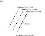
- the skeleton generation unit 14c is a first method for generating a probe data group having the largest number of data per unit length from a plurality of probe data groups corresponding to the lane markings as a skeleton.
- the second method of generating the probe data group closest to the road center line as a skeleton from a plurality of probe data groups corresponding to, the skeleton is the reference line when multiple input maps are integrated to generate an integrated input map.
- the skeleton is generated by adopting one of the third methods of generating as.
- the skeleton generation unit 14c when the first method is adopted, as shown in FIG. 3, in the skeleton generation unit 14c, the difference in the number of data in the plurality of probe data groups corresponding to the lane markings A to C is equal to or larger than the threshold value. If so, the probe data group having the largest number of data per unit length is generated as a skeleton from the plurality of probe data groups. In the example of FIG. 3, the skeleton generation unit 14c generates the probe data group of the lane marking C as a skeleton from the probe data group of the lane markings A to C.
- the second method is adopted, as shown in FIG.
- the skeleton generation unit 14c is a plurality of probe data groups corresponding to the lane markings A to C if the difference in the number of data is less than the threshold value.
- the probe data group closest to the road center line is generated as a skeleton from the probe data group of.
- the skeleton generation unit 14c generates the probe data group of the lane marking F as a skeleton from the probe data group of the lane markings D to F.
- the skeleton generation unit 14c When the third method is adopted, as shown in FIG. 5, the skeleton generation unit 14c generates a reference line as a skeleton when a plurality of input maps are integrated to generate an integrated input map.
- the skeleton generation unit 14c generates the reference lines G and H when the integrated input map is generated as the skeleton.
- the division section data generation unit 14d divides the generated skeleton at the division point to generate the division section data.
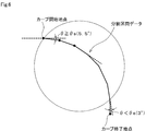
- the divided section data generation unit 14d presets the curve start angle ( ⁇ s) and the curve end angle ( ⁇ e), and starts the curve at a point where the amount of change in orientation is equal to or greater than the curve start angle. It is set as a point, and the point where the amount of change in orientation is less than the curve end angle is set as the curve end point.
- the curve start angle is, for example, 5.5 degrees
- the curve end angle is, for example, 3 degrees.
- the division section data generation unit 14d sets the set curve start point and curve end point as division points, and generates the division section data between the set division points. In this case, as shown in FIG. 7, the divided section data generation unit 14d calculates the cumulative value of the directional change amount from the time when the directional change amount becomes equal to or more than the curve start angle to the time when the directional change amount becomes less than the curve end angle as the turning angle. ..
- the offset value calculation unit 14e calculates the offset value between the input map and the reference map for each section corresponding to the generated divided section data. ..
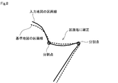
- the map processing unit 14f corrects the position of the input map based on the reference map using the calculated offset value. That is, the map processing unit 14f superimposes the reference map and the input map so that the feature points included in the reference map and the feature points included in the input map overlap, and corrects the position of the input map. As shown in FIG. 8, the map processing unit 14f corrects the position of the input map based on the reference map by using the offset value for each section corresponding to the divided section data.
- the map processing unit 14f generates the divided section data and corrects each section corresponding to the generated divided section data, so that the deviation between the maps is partially different. It is possible to avoid this in advance, and it is possible to appropriately eliminate the deviation between the maps over a wide area.
- the difference detection unit 14g corrects the position of the input map based on the reference map, and determines that the positions of at least four feature points match between the reference map and the input map. It is judged to be successful, and the difference between the reference map and the input map is detected.
- the difference detection unit 14g reflects static information and dynamic information as the difference on the reference map.
- the static information includes feature point information regarding feature points, demarcation line information regarding demarcation lines, position information of points, and the like.
- the feature point information includes position coordinates indicating the position of the feature point, an ID for identifying the feature point, a size of the feature point, a shape of the feature point, a color of the feature point, a type of the feature point, and the like.
- the lane marking information includes position coordinates indicating the position of the lane marking, an ID for identifying the lane marking, a type of broken line or a solid line, and the like.
- the position information of the point is GPS coordinates or the like indicating a point on the road.
- the dynamic information is vehicle information about a vehicle on the road, such as vehicle speed value, turn signal operation information, lane straddle, steering angle value, yaw rate value, GPS coordinates, and the like.
- the control unit 14 when the control unit 14 starts the position correction process of the input map, the control unit 14 generates a skeleton representing the road shape from the input map (S1, corresponding to the skeleton generation procedure).
- the generated skeleton is divided at the division points to generate the division section data (S2, which corresponds to the division section data generation procedure).
- the control unit 14 sets any of the divided section data as the position correction target section (S3), and calculates the offset value between the input map and the reference map for the divided section data set as the position correction target section (S3).
- S4 corresponding to the offset value calculation procedure).
- the control unit 14 calculates the offset value
- the control unit 14 corrects the position of the input map based on the reference map using the calculated offset value (S5).
- the control unit 14 determines whether or not the input map is position-corrected based on the reference map for all the division section data (S6), and the input map is position-corrected based on the reference map for all the division section data. If it is determined that there is no such condition (S6: NO), a new position correction target section is set (S7), the process returns to step S4 described above, and steps S4 and subsequent steps are repeated.
- the control unit 14 determines that the position of the input map has been corrected based on the reference map for all the divided section data (S6: YES)
- the control unit 14 ends the position correction process of the input map.
- a skeleton representing the road shape is generated from the input map, the generated skeleton is divided at the division points to generate the division section data, and the input map is used for each section corresponding to the generated division section data.
- the offset value with the reference map is calculated.
- the position of the input map was corrected based on the calculated offset value.
- the probe data group having the largest number of data per unit length is generated as a skeleton from a plurality of probe data groups corresponding to the section line.
- a skeleton can be generated by identifying the probe data group having the largest number of data per unit length.
- the probe data group closest to the road center line is generated as a skeleton from a plurality of probe data groups corresponding to the lane markings.
- a skeleton can be generated by identifying the probe data group closest to the road centerline.
- the reference line when a plurality of input maps are integrated and an integrated input map is generated is generated as a skeleton.
- a skeleton can be generated by specifying the reference line when the integrated input map is generated.
- the controls and methods thereof described in the present disclosure are realized by a dedicated computer provided by configuring a processor and memory programmed to perform one or more functions embodied by a computer program. May be.
- the control unit and its method described in the present disclosure may be realized by a dedicated computer provided by configuring a processor with one or more dedicated hardware logic circuits.
- the control unit and method thereof described in the present disclosure may be a combination of a processor and memory programmed to perform one or more functions and a processor composed of one or more hardware logic circuits. It may be realized by one or more dedicated computers configured.
- the computer program may be stored in a computer-readable non-transitional tangible recording medium as an instruction executed by the computer.
- the server 3 exemplifies a configuration in which a segment that does not include a predetermined number or more of feature points and a segment that does not include a predetermined number or more of feature points whose detection level is a predetermined level or higher are not included in the acquisition target.
- the condition for transmitting the probe data including the segment to the server 3 may be set. That is, in the vehicle-mounted device 2, for example, a configuration in which probe data is transmitted to the server 3 every time a predetermined time elapses or the mileage of the vehicle reaches a predetermined distance is illustrated, but the number of detected feature points included in the segment is detected. , And the probe data may be transmitted to the server 3 only when the number of detected feature points is a predetermined number or more.
- the number of detected feature points may not be equal to or greater than a predetermined number due to the presence of a preceding vehicle, and even if probe data including segments including segments whose number of detected feature points is not equal to or greater than a predetermined number is transmitted to the server 3, the probe data may be transmitted. If it is assumed that the server 3 will be discarded without being processed, the probe data may not be transmitted to the server 3. By not transmitting probe data unnecessary for the server 3 from the vehicle-mounted device 2, the load of data communication can be reduced.
Landscapes
- Engineering & Computer Science (AREA)
- Radar, Positioning & Navigation (AREA)
- Remote Sensing (AREA)
- Physics & Mathematics (AREA)
- Automation & Control Theory (AREA)
- General Physics & Mathematics (AREA)
- Geometry (AREA)
- Instructional Devices (AREA)
- Traffic Control Systems (AREA)
- Navigation (AREA)
Priority Applications (4)
| Application Number | Priority Date | Filing Date | Title |
|---|---|---|---|
| DE112021003191.0T DE112021003191T5 (de) | 2020-07-10 | 2021-06-15 | Kartenverarbeitungssystem und kartenverarbeitungsprogramm |
| CN202180048374.9A CN115777122A (zh) | 2020-07-10 | 2021-06-15 | 地图处理系统以及地图处理程序 |
| JP2022534984A JP7380886B2 (ja) | 2020-07-10 | 2021-06-15 | 地図処理システム及び地図処理プログラム |
| US18/151,000 US20230146156A1 (en) | 2020-07-10 | 2023-01-06 | Map processing system and non-transitory computer-readable storage medium having map processing program stored thereon |
Applications Claiming Priority (2)
| Application Number | Priority Date | Filing Date | Title |
|---|---|---|---|
| JP2020119193 | 2020-07-10 | ||
| JP2020-119193 | 2020-07-10 |
Related Child Applications (1)
| Application Number | Title | Priority Date | Filing Date |
|---|---|---|---|
| US18/151,000 Continuation US20230146156A1 (en) | 2020-07-10 | 2023-01-06 | Map processing system and non-transitory computer-readable storage medium having map processing program stored thereon |
Publications (1)
| Publication Number | Publication Date |
|---|---|
| WO2022009624A1 true WO2022009624A1 (ja) | 2022-01-13 |
Family
ID=79552940
Family Applications (1)
| Application Number | Title | Priority Date | Filing Date |
|---|---|---|---|
| PCT/JP2021/022688 Ceased WO2022009624A1 (ja) | 2020-07-10 | 2021-06-15 | 地図処理システム及び地図処理プログラム |
Country Status (5)
| Country | Link |
|---|---|
| US (1) | US20230146156A1 (https=) |
| JP (1) | JP7380886B2 (https=) |
| CN (1) | CN115777122A (https=) |
| DE (1) | DE112021003191T5 (https=) |
| WO (1) | WO2022009624A1 (https=) |
Citations (5)
| Publication number | Priority date | Publication date | Assignee | Title |
|---|---|---|---|---|
| JP2004177862A (ja) * | 2002-11-29 | 2004-06-24 | Hitachi Ltd | 地図位置補正装置および方法 |
| JP2004226730A (ja) * | 2003-01-23 | 2004-08-12 | Denso Corp | 地図データ作成方法及び装置、地図データ記録媒体、地図データ利用装置、地図データ作成プログラム |
| JP2005070482A (ja) * | 2003-08-26 | 2005-03-17 | Mitsubishi Electric Corp | 地図データのデータ構造、地図データ格納媒体、地図データの更新方法、および地図情報処理装置 |
| WO2015125265A1 (ja) * | 2014-02-21 | 2015-08-27 | 三菱電機株式会社 | 地図情報処理装置、地図情報処理方法及び更新データの調整方法 |
| JP2019179217A (ja) * | 2018-03-30 | 2019-10-17 | 日産自動車株式会社 | 地図補正方法及び地図補正装置 |
Family Cites Families (3)
| Publication number | Priority date | Publication date | Assignee | Title |
|---|---|---|---|---|
| JP5064870B2 (ja) * | 2007-04-17 | 2012-10-31 | 株式会社日立製作所 | デジタル道路地図の生成方法及び地図生成システム |
| EP3614366A4 (en) * | 2017-11-22 | 2020-12-23 | Micware Co., Ltd. | DEVICE, METHOD AND PROGRAM FOR PROCESSING CARTOGRAPHIC INFORMATION |
| JP7120042B2 (ja) | 2019-01-23 | 2022-08-17 | トヨタ自動車株式会社 | 自動駐車管理サーバ |
-
2021
- 2021-06-15 CN CN202180048374.9A patent/CN115777122A/zh active Pending
- 2021-06-15 WO PCT/JP2021/022688 patent/WO2022009624A1/ja not_active Ceased
- 2021-06-15 DE DE112021003191.0T patent/DE112021003191T5/de active Pending
- 2021-06-15 JP JP2022534984A patent/JP7380886B2/ja active Active
-
2023
- 2023-01-06 US US18/151,000 patent/US20230146156A1/en not_active Abandoned
Patent Citations (5)
| Publication number | Priority date | Publication date | Assignee | Title |
|---|---|---|---|---|
| JP2004177862A (ja) * | 2002-11-29 | 2004-06-24 | Hitachi Ltd | 地図位置補正装置および方法 |
| JP2004226730A (ja) * | 2003-01-23 | 2004-08-12 | Denso Corp | 地図データ作成方法及び装置、地図データ記録媒体、地図データ利用装置、地図データ作成プログラム |
| JP2005070482A (ja) * | 2003-08-26 | 2005-03-17 | Mitsubishi Electric Corp | 地図データのデータ構造、地図データ格納媒体、地図データの更新方法、および地図情報処理装置 |
| WO2015125265A1 (ja) * | 2014-02-21 | 2015-08-27 | 三菱電機株式会社 | 地図情報処理装置、地図情報処理方法及び更新データの調整方法 |
| JP2019179217A (ja) * | 2018-03-30 | 2019-10-17 | 日産自動車株式会社 | 地図補正方法及び地図補正装置 |
Also Published As
| Publication number | Publication date |
|---|---|
| CN115777122A (zh) | 2023-03-10 |
| JP7380886B2 (ja) | 2023-11-15 |
| US20230146156A1 (en) | 2023-05-11 |
| JPWO2022009624A1 (https=) | 2022-01-13 |
| DE112021003191T5 (de) | 2023-04-20 |
Similar Documents
| Publication | Publication Date | Title |
|---|---|---|
| EP3637371B1 (en) | Map data correcting method and device | |
| JP5152244B2 (ja) | 追従対象車特定装置 | |
| US9767372B2 (en) | Target detection apparatus and target detection method | |
| US20200072617A1 (en) | Host vehicle position estimation device | |
| CN114323050A (zh) | 车辆定位方法、装置和电子设备 | |
| CN113566817B (zh) | 一种车辆定位方法及装置 | |
| CN112284416A (zh) | 一种自动驾驶定位信息校准装置、方法及存储介质 | |
| JP7421923B2 (ja) | 位置推定装置、及び位置推定方法 | |
| WO2018037653A1 (ja) | 車両制御システム、自車位置算出装置、車両制御装置、自車位置算出プログラム及び車両制御プログラム | |
| CN114729812B (zh) | 估计装置、估计方法、存储介质 | |
| US12228421B2 (en) | Map update device and storage medium | |
| WO2021035748A1 (zh) | 位姿获取方法、系统和可移动平台 | |
| US20230160701A1 (en) | Map processing system and non-transitory computer-readable storage medium having map processing program stored thereon | |
| JP6925428B2 (ja) | 測定装置、測定方法、及び、プログラム | |
| JP7380886B2 (ja) | 地図処理システム及び地図処理プログラム | |
| CN113795726B (zh) | 自身位置修正方法及自身位置修正装置 | |
| CN116448146A (zh) | 一种惯性导航系统自标定方法、装置、设备及存储介质 | |
| JP2019045341A (ja) | 車両位置検出方法及び車両位置検出装置 | |
| US20240200977A1 (en) | Map data generation device, map data generation system, and storage medium | |
| US11066078B2 (en) | Vehicle position attitude calculation apparatus and vehicle position attitude calculation program | |
| RU2781373C1 (ru) | Способ коррекции собственного местоположения и устройство коррекции собственного местоположения | |
| JP6907952B2 (ja) | 自己位置補正装置及び自己位置補正方法 | |
| KR20260017141A (ko) | 카메라 영상 평탄화 기반 gps 오프셋 보정 장치 및 방법 | |
| KR20250032681A (ko) | 깊이 맵 생성 장치 및 방법 | |
| CN120176665A (zh) | 车辆的定位方法、装置、车辆及存储介质 |
Legal Events
| Date | Code | Title | Description |
|---|---|---|---|
| 121 | Ep: the epo has been informed by wipo that ep was designated in this application |
Ref document number: 21837845 Country of ref document: EP Kind code of ref document: A1 |
|
| ENP | Entry into the national phase |
Ref document number: 2022534984 Country of ref document: JP Kind code of ref document: A |
|
| 122 | Ep: pct application non-entry in european phase |
Ref document number: 21837845 Country of ref document: EP Kind code of ref document: A1 |