WO2022004389A1 - 演算装置、学習方法、およびニューラルネットワークの作成方法 - Google Patents
演算装置、学習方法、およびニューラルネットワークの作成方法 Download PDFInfo
- Publication number
- WO2022004389A1 WO2022004389A1 PCT/JP2021/022886 JP2021022886W WO2022004389A1 WO 2022004389 A1 WO2022004389 A1 WO 2022004389A1 JP 2021022886 W JP2021022886 W JP 2021022886W WO 2022004389 A1 WO2022004389 A1 WO 2022004389A1
- Authority
- WO
- WIPO (PCT)
- Prior art keywords
- calculation
- region
- layer
- feature map
- path
- Prior art date
- Legal status (The legal status is an assumption and is not a legal conclusion. Google has not performed a legal analysis and makes no representation as to the accuracy of the status listed.)
- Ceased
Links
Images





Classifications
-
- G—PHYSICS
- G06—COMPUTING OR CALCULATING; COUNTING
- G06N—COMPUTING ARRANGEMENTS BASED ON SPECIFIC COMPUTATIONAL MODELS
- G06N3/00—Computing arrangements based on biological models
- G06N3/02—Neural networks
- G06N3/04—Architecture, e.g. interconnection topology
- G06N3/0464—Convolutional networks [CNN, ConvNet]
-
- G—PHYSICS
- G06—COMPUTING OR CALCULATING; COUNTING
- G06N—COMPUTING ARRANGEMENTS BASED ON SPECIFIC COMPUTATIONAL MODELS
- G06N3/00—Computing arrangements based on biological models
- G06N3/02—Neural networks
- G06N3/04—Architecture, e.g. interconnection topology
-
- G—PHYSICS
- G06—COMPUTING OR CALCULATING; COUNTING
- G06N—COMPUTING ARRANGEMENTS BASED ON SPECIFIC COMPUTATIONAL MODELS
- G06N3/00—Computing arrangements based on biological models
- G06N3/02—Neural networks
- G06N3/08—Learning methods
-
- G—PHYSICS
- G06—COMPUTING OR CALCULATING; COUNTING
- G06N—COMPUTING ARRANGEMENTS BASED ON SPECIFIC COMPUTATIONAL MODELS
- G06N3/00—Computing arrangements based on biological models
- G06N3/02—Neural networks
- G06N3/08—Learning methods
- G06N3/09—Supervised learning
Definitions
- This disclosure relates to an arithmetic unit using a neural network, a learning method, and a method of creating a neural network.
- Non-Patent Document 1 a configuration of a neural network that recognizes according to the result of learning based on the content of data has been proposed (see, for example, Non-Patent Document 1).
- the arithmetic unit includes a generation unit that generates a first feature map and a second feature map having a common feature amount in the channel direction based on input data, a first region in which the first feature map is input, and a generation unit.
- An input layer having a second area in which a second feature map is input in the channel direction, and a third area in which calculation results corresponding to the first area are output and a fourth area in which calculation results corresponding to the second area are output.
- a neural network having an output layer having a region in the channel direction is provided with an arithmetic unit, and the third region is coupled to a first region and at least a part of a second region, and a second region is provided.
- the operational coefficient of the coupling from to the third region is set to substantially zero
- the fourth region is coupled to the second region and at least a part of the first region, and from the first region to the fourth region.
- the operation factor of the combination is set to substantially zero.
- the learning method includes a first step of generating a first feature map and a second feature map having a common feature amount in the channel direction based on input data, and a first region in which the first feature map is input. And an input layer having a second area in which the second feature map is input in the channel direction, and a third area in which calculation results corresponding to the first area are output and calculation results corresponding to the third area and the second area are output.
- the second step includes a third step to be updated, the second step is a step of joining the third region to the first region and at least a part of the second region, and the fourth region is one of the second region and at least the first region.
- the third step is such that the calculation coefficient of the connection from the second region to the third region and the calculation coefficient of the connection from the first region to the fourth region become substantially zero. , Includes steps to update the arithmetic coefficients.
- the learning method includes a first step of generating a first feature map and a second feature map having a common feature amount in the channel direction based on input data, and a first region in which the first feature map is input. And an input layer having a second area in which the second feature map is input in the channel direction, and a third area in which calculation results corresponding to the first area are output and calculation results corresponding to the third area and the second area are output.
- the second step includes a third step to be updated, the second step is a step of joining the third region to the first region and at least a part of the second region, and the fourth region is one of the second region and at least the first region.
- the third step including the step of joining the parts, keeps the calculation coefficient of the connection from the second region to the third region and the calculation coefficient of the connection from the first region to the fourth region substantially zero. However, it includes a step of updating the arithmetic coefficients of other combinations.
- the method for creating a neural network includes a first calculation path and a first calculation path so as to have one or more calculation layers for outputting the result of executing a predetermined calculation using a calculation coefficient for the feature amount of the input feature map.
- a step of inputting teacher data and updating the calculation coefficient of the calculation layer, and a step of connecting the corresponding layers in the first calculation path and the second calculation path where the calculation coefficient is updated in the channel direction include.
- the method for creating a neural network includes a first calculation path and a first calculation path so as to have one or more calculation layers for outputting the result of executing a predetermined calculation using a calculation coefficient for the feature amount of the input feature map.
- an auxiliary arithmetic layer that executes the same operation as the arithmetic layer arranged at the corresponding position at the position where the arithmetic layer corresponding to the arithmetic layer arranged in the first arithmetic path is not arranged in the second arithmetic path.
- FIG. 1 is a schematic diagram showing a schematic configuration of a computer.
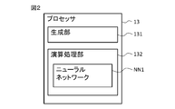
- FIG. 2 is a functional block diagram of the processor.
- FIG. 3 is a diagram illustrating the generation of the feature map by the generation unit.
- FIG. 4 is a schematic diagram showing the structure of the neural network.
- FIG. 5 is a first flowchart of the first process of creating a neural network.
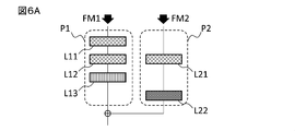
- FIG. 6A is a diagram showing a first state in the first process of creating a neural network.
- FIG. 6B is a diagram showing a second state in the first process of creating a neural network.
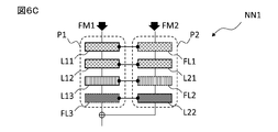
- FIG. 6C is a diagram showing a third state in the first process of creating a neural network.
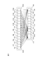
- FIG. 7 is a diagram showing a first example of coupling in a calculation path.
- FIG. 1 is a schematic diagram showing a schematic configuration of a computer.
- FIG. 2 is a functional block diagram of the processor.
- FIG. 3 is a diagram illustrating the generation of the feature map by the generation unit.
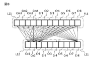
- FIG. 8 is a diagram showing a second example of coupling in the calculation path.
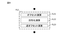
- FIG. 9 is a diagram showing an outline of the activation operation in the auxiliary operation layer.
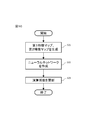
- FIG. 10 is an operation flowchart of the learning process.
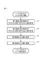
- FIG. 11 is a flowchart of the second process of creating the neural network.
- FIG. 12 is a second flowchart of the first process of creating a neural network.
- FIG. 13 is a third flowchart of the first process of creating a neural network.
- FIG. 14 is a schematic diagram showing the configuration of a camera equipped with an arithmetic unit.
- FIG. 15 is a processing flowchart of a camera equipped with an arithmetic unit.
- FIG. 1 is a schematic diagram showing a schematic configuration of a computer
- FIG. 2 is a functional block diagram of a processor.
- the computer 1 which is an example of the arithmetic unit generates a feature map based on predetermined input data, inputs the feature map to the neural network, and outputs the calculation result. Therefore, the computer 1 includes an input / output interface 11, a memory 12, and a processor 13.
- the input / output interface 11 has an interface circuit for receiving data to be processed by the computer 1 or outputting the data processed by the computer 1.
- the input / output interface 11 includes, for example, a communication interface circuit for connecting the computer 1 to a communication network, or a peripheral device interface circuit for connecting the computer 1 to various peripheral devices such as a keyboard and a display.
- the input / output interface 11 accepts input of predetermined data and outputs a processing result.
- the memory 12 is an example of a storage unit, and has, for example, at least one of a semiconductor memory, a magnetic disk device, and an optical disk device.
- the memory 12 stores a driver program, an operating system program, an application program, data, and the like used for processing by the processor 13.
- the memory 12 stores, as an application program, a computer program for realizing the arithmetic processing of the present disclosure.
- the memory 12 stores as data a parameter group (number of layers, layer configuration, kernel, weighting coefficient, etc.) for defining the neural network.
- the various programs may be installed in the memory 12 from a computer-readable portable recording medium using a known setup program or the like.
- the computer-readable portable recording medium is, for example, a CD-ROM (Compact Disc Read-Only Memory), a DVD-ROM (DVD Read-Only Memory), or the like.
- the processor 13 includes one or more processors and their peripheral circuits.
- the processor 13 is a processing circuit that comprehensively controls the overall operation of the computer 1, and is, for example, a CPU (Central Processing Unit).
- the processor 13 may have a GPU (Graphics Processing Unit) capable of processing a large number of routine operations in parallel.
- the processor 13 controls the operation of the input / output interface 11 and the like so that various processes of the computer 1 are executed by appropriate means based on the program and the like stored in the memory 12.
- the processor 13 executes processing based on a program (operating system program, driver program, application program, etc.) stored in the memory 12. Further, the processor 13 can execute a plurality of programs (application programs and the like) in parallel.
- the processor 13 has a generation unit 131 for generating a feature map based on the input input data, and an arithmetic processing unit 132 for executing an operation by the neural network NN1.
- the arithmetic processing unit 132 is a functional module implemented by a program executed on the processor of the processor 13.
- the arithmetic processing unit 132 may be mounted on the computer 1 as an independent integrated circuit, microprocessor, or firmware.
- FIG. 3 is a diagram illustrating the generation of the feature map by the generation unit 131.
- the generation unit 131 generates the first feature map FM1 and the second feature map FM2 based on the input data ID.
- the input data ID is, for example, image data having an RGB corresponding value for each pixel.
- the feature amount in the channel (C) direction is common. That is, in the first feature map FM1 and the second feature map FM2, the feature amounts in the corresponding channels are the same.
- the generation unit 131 generates the first feature map FM1 and the second feature map FM2 by performing predetermined operations such as a convolution operation, a transposed convolution operation, a pooling operation, and an activation operation on the input data ID.
- the generation unit 131 generates the first feature map FM1 and the second feature map FM2 by executing a convolution operation for each pixel of each of RGB for the input data ID which is image data, for example. Further, the generation unit 131 may generate the same data as the input data ID as the first feature map FM1 and the second feature map FM2.
- FIG. 4 is a schematic diagram showing the structure of the neural network NN1.
- the first feature map FM1 and the second feature map FM2 generated based on the input data ID by the above-mentioned generation unit 131 are input to the neural network NN1. Then, the neural network NN1 performs at least one of a convolution operation, a transposed convolution operation, a pooling operation, and an activation operation on the first feature map FM1 and the second feature map FM2, and outputs the output data OD.
- the neural network NN1 is learned according to the error back propagation method by using a plurality of images showing an object to be detected and information indicating the position, type, etc. of the object on each image as training data.
- the neural network NN1 is, for example, a ResNet having a convolution calculation path and a skip connection calculation path.
- the neural network NN1 detects an object represented by the image data, for example, based on the input of the image data.
- the neural network NN1 includes an input layer IL and an output layer OL.
- the input layer IL has a first region R1 and a second region R2 in the channel direction.
- the first feature map FM1 generated based on the input data ID is input to the first area R1.
- the second feature map FM2 generated based on the input data ID is input to the second area R2.
- the output layer OL has a third region R3 and a fourth region R4 in the channel direction.
- the third region R3 is coupled to the first region R1. Further, the third region R3 is bound to at least a part of the second region R2. At this time, the calculation coefficient of the coupling from the second region R2 to the third region R3 is set to substantially zero.
- the fourth region R4 is combined with the second region R2. Further, the fourth region R4 is bound to at least a part of the first region R1. At this time, the calculation coefficient of the coupling from the first region R1 to the fourth region R4 is set to substantially zero.
- the neural network NN1 generates and outputs output data OD based on the output of the third region R3 and the output of the fourth region R4.
- the fact that the calculation coefficient of the combination is set to substantially zero means that the calculation coefficient is set so that the feature amount of the previous layer does not affect the result of the calculation in the subsequent layer. Good, details will be described later.
- the neural network NN1 may have at least one intermediate layer, preferably a plurality of intermediate layers, between the input layer IL and the output layer OL.
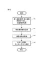
- FIG. 5 is the first flowchart of the neural network creation first process
- FIGS. 6 (a)-(c) are diagrams showing the state of the neural network in the neural network creation first process.
- the computer can create the neural network NN1 by executing the processing of each step shown in FIG.
- the computer creates a first calculation path P1 and a second calculation path P2 each having one or more calculation layers. Then, each calculation layer is arranged so that the position of the calculation layer that executes the same calculation is the corresponding position in the first calculation path P1 and the second calculation path P2 (step S11).
- FIG. 6A shows a state in which a first calculation path P1 having three calculation layers L11-L13 and a second calculation path P2 having two calculation layers L21-L22 are created and each calculation layer is arranged. There is.
- the first calculation path P1 has calculation layers L11 and L12 for executing the convolution calculation, and calculation layers L13 for executing the activation calculation.
- a first feature map FM1 having a dimension of W ⁇ H ⁇ Ci is input to the first calculation path P1 (W represents a width, H represents a height, and C represents a channel).
- the calculation layer L11 executes a convolution operation using, for example, a 3 ⁇ 3 kernel on the input first feature map FM1, and outputs a feature map having a dimension of W ⁇ H ⁇ Cm.
- the calculation layer L12 executes a convolution operation using, for example, a 3 ⁇ 3 kernel on the feature map output from the calculation layer L11, and outputs a feature map having a dimension of W ⁇ H ⁇ Co.
- the calculation layer L13 executes an activation operation by, for example, a ReLU function on the feature map output from the calculation layer L12, and outputs a feature map having a dimension of W ⁇ H ⁇ Co.
- the second calculation path P2 has calculation layers L21 and L22 for executing the convolution calculation.
- a second feature map FM2 having a dimension of W ⁇ H ⁇ Ci is input to the second calculation path P2.
- the calculation layer L21 executes a convolution operation using, for example, a 3 ⁇ 3 kernel on the input second feature map FM2, and outputs a feature map having a dimension of W ⁇ H ⁇ Cr.
- the calculation layer L22 executes a convolution operation using, for example, a 1 ⁇ 1 kernel on the feature map output from the calculation layer L21, and outputs a feature map having a dimension of W ⁇ H ⁇ Co.
- the sum of the output of the first calculation path P1 and the output of the second calculation path is passed to the next process as the output of the neural network NN1.
- the computer is arranged at a position where the calculation layer corresponding to the calculation layer arranged in the second calculation path P2 is not arranged in the first calculation path P1, and is arranged in the first calculation path P1 in the second calculation path.
- An auxiliary arithmetic layer is added at a position where the arithmetic layer corresponding to the arithmetic layer is not arranged (step S12).
- the calculation layer corresponding to the calculation layer L22 arranged in the second calculation path P2 is not arranged.
- the calculation layer corresponding to the calculation layer L11 and the calculation layer L13 arranged in the first calculation path P1 is not arranged.
- the computer adds the auxiliary arithmetic layers FL1-FL3 as shown in FIG. 6B.
- the auxiliary calculation layer FL1 is a calculation layer that executes a convolution operation similar to the calculation layer L11.
- the auxiliary calculation layer FL2 is a calculation layer that executes the same activation calculation as the calculation layer L13.
- the auxiliary calculation layer FL3 is a calculation layer that executes a convolution operation similar to the calculation layer L22. Further, in the auxiliary calculation layer FL1-3, the calculation coefficient is set so as to output a feature amount substantially equal to the input feature amount.
- connecting arithmetic layers in the channel direction means connecting a plurality of arithmetic layers in the channel direction to form one arithmetic layer.
- the arithmetic layer L11 and the auxiliary arithmetic layer FL1 the arithmetic layer L12 and the arithmetic layer L21, the arithmetic layer L13 and the auxiliary arithmetic layer FL2, the auxiliary arithmetic layer FL3 and the arithmetic layer L22 are arranged at the corresponding positions.
- Each is connected in the channel direction.
- Each layer connected at the corresponding positions of the first calculation path P1 and the second calculation path P2 performs the same operation on the input feature map.
- the layer in which the calculation layer L11 and the auxiliary calculation layer FL1 are connected can perform a convolution operation using a 3 ⁇ 3 kernel on the feature map in which the first feature map FM1 and the second feature map FM2 are connected. Execute and output a feature map having a dimension of W ⁇ H ⁇ (Cm + Cr).
- the calculation coefficient of the connection from the first calculation path P1 to the second calculation path P2 and the calculation coefficient of the connection from the second calculation path P2 to the first calculation path P1 are set to substantially zero. ..
- FIG. 7 is a diagram showing a first example of a connection in a calculation path
- FIG. 8 is a diagram showing a second example of a connection in a calculation path.
- each node in the calculation path is connected in the channel direction.
- FIG. 7 shows an example of the combination of the first feature map FM1 and the second feature map FM2 with the connected arithmetic layer L11 and auxiliary arithmetic layer FL1.
- the calculation layer L11 is included in the first calculation path P1, and the first feature map FM1 is input.
- the auxiliary calculation layer FL1 is included in the second calculation path P2, and the second feature map FM2 is input. Some channels included in the first feature map FM1 are also included in the second feature map FM2.
- the arithmetic layer L11 and the auxiliary arithmetic layer FL1 correspond to the input layer IL.
- Each channel Ci1-Ci16 of the first feature map FM1 and the second feature map FM2 is fully coupled to each channel Cm1-Cm4 of the calculation layer L11. Further, each channel Ci1-Ci16 of the first feature map FM1 and the second feature map FM2 is fully coupled to each channel Cr1-Cr8 of the auxiliary calculation layer FL1.
- the calculation coefficient of the connection between each channel Cm1-Cm4 of the calculation layer L11 and the channel Ci11-Ci16 not included in the first feature map FM1 among the channels of the second feature map FM2 is set to substantially zero.
- the calculation coefficient of the coupling other than the coupling between each channel Cr1-Cr8 of the auxiliary calculation layer FL1 and the corresponding channels Ci9-Ci16 is set to substantially zero.
- Equation 1 the weight W, which is an arithmetic coefficient used for the convolution operation executed in the arithmetic layer L11 and the auxiliary arithmetic layer FL1, is set as in Equation 2 shown below.
- the weight of the bond in the arithmetic layer L11 is W f1
- the weight of the bond in the auxiliary arithmetic layer FL1 is W h1 .
- W f1 the weight of the connection with the first feature map FM1 is updated by learning, and the weight of the connection with the channel of the second feature map FM2 not included in the first feature map FM1 becomes substantially zero. Is set.
- the weight of the connection with the channel not included in the second feature map FM2 in the first feature map FM1 is set to be substantially zero, and the weight of the connection with the second feature map FM2 is set to be substantially zero.
- the weight of the connection between the corresponding channels of the second feature map FM2 and the auxiliary calculation layer FL1 is a predetermined value (for example, 1), and the weight of the connection with other channels is substantially 0. It is preset to be, and is not updated by learning.
- Equation 3 By setting W h1 as shown in Equation 3 below, a value equal to that of the second feature map FM2 can be output from the auxiliary calculation layer FL1 in the convolution calculation in the auxiliary calculation layer FL1.
- ⁇ is a Kronecker delta.
- the range of r and s is-(k-1) / 2 to (k-1) / 2, and cr > co .
- FIG. 8 shows an example of the connection between the connected arithmetic layer L11 and the auxiliary arithmetic layer FL1 and the concatenated arithmetic layer L12 and the arithmetic layer L21.
- the calculation layer L11 and the calculation layer L12 are included in the first calculation path P1.
- the auxiliary calculation layer FL1 and the calculation layer L21 are included in the second calculation path P2.
- the arithmetic layer L12 and the arithmetic layer L21 correspond to an intermediate layer between the input layer IL and the output layer OL.
- Each channel Cm1-Cm4 of the arithmetic layer L11 and each channel Cr1-Cr8 of the auxiliary arithmetic layer FL1 are fully coupled to each channel Co1 and Co2 of the arithmetic layer L12.
- the calculation coefficient of the coupling between each channel Co1 and Co2 of the calculation layer L12 and each channel Cr1-Cr8 of the auxiliary calculation layer FL1 is set to substantially zero.
- each channel Cm1-Cm4 of the arithmetic layer L11 and each channel Cr1-Cr8 of the auxiliary arithmetic layer FL1 are fully coupled to each channel Cr1-Cr8 of the arithmetic layer L21.
- the calculation coefficient of the coupling between each channel Cr1-Cr8 of the calculation layer L21 and each channel Cm1-Cm4 of the calculation layer L11 is set to substantially zero.
- Equation 4 the weight W, which is the calculation coefficient in Equation 1, is set as in Equation 4 shown below.
- the weight of the connection between the arithmetic layer L11 and the arithmetic layer L12 is W f2
- the weight of the coupling between the auxiliary arithmetic layer FL1 and the arithmetic layer L12 are 0.
- the weight of the connection between the auxiliary arithmetic layer FL1 and the arithmetic layer L21 is W h2 .
- W f2 is set so that the arithmetic layer L11 and the arithmetic layer L12 are fully connected in the channel direction, and is updated by learning.
- W h2 is preset and is not updated by learning.
- the output of the auxiliary calculation layer FL3 and the calculation layer L22 can be set. You can perform sum operations with the output. That is, the weight used for the calculation of the auxiliary calculation layer FL3 is W h3, and the weight used for the calculation of the calculation layer L22 is W f3 .
- ⁇ is a coefficient tensor set according to the weight ratio required for the sum of the output of the auxiliary arithmetic layer FL3 and the output of the arithmetic layer L22. The value of ⁇ may be 1.
- FIG. 9 is a diagram showing an outline of the activation operation in the auxiliary operation layer FL2.
- the auxiliary calculation layer FL2 executes the same activation calculation as the calculation layer L13, and the calculation coefficient is set to substantially zero. Since the calculation coefficient is substantially zero for the activation calculation, the auxiliary calculation layer FL2 has an offset calculation layer FL21, an activation calculation layer FL22, and an inverse offset calculation layer FL23 in this order from the input side.
- the auxiliary calculation layer FL2 executes the offset calculation by the offset calculation layer FL21 immediately before the activation calculation by the activation calculation layer FL22, and executes the reverse offset calculation by the inverse offset calculation layer FL23 immediately after the activation calculation.
- the offset operation is an operation of converting an input value into a range in which the value does not substantially change before and after the activation operation.
- the inverse offset operation is an operation of converting the value converted by the offset operation into the original input value.
- the offset calculation layer FL21 can execute the offset calculation by adding a predetermined positive value to the input value.
- the inverse offset calculation layer FL23 can execute the inverse offset calculation by subtracting a predetermined positive value added by the offset calculation from the input value.
- the offset calculation layer FL21 may perform normalization of the input value, for example, by performing batch normalization for the input value.
- the offset operation for the activation operation by the ReLU function can be executed by normalizing so that ⁇ is 1 and ⁇ is a sufficiently large value. Further, by normalizing ⁇ to 0 and ⁇ to a sufficiently large value, it is possible to execute an offset operation for the activation operation by the sigmoid function.
- the inverse offset calculation layer FL23 executes an operation that cancels the calculation in the offset calculation layer FL21.
- the offset calculation layer FL21 may be implemented by setting the bias of the convolution calculation to a value other than 1 in the previous calculation layer.
- the inverse offset calculation layer FL23 may be implemented by setting the bias of the convolution calculation to a value other than 1 in the later calculation layer.
- the offset calculation layer FL21 may output the input value as it is.
- the inverse offset calculation layer FL23 executes an operation by the inverse function of the sigmoid function and obtains the original input value.
- the neural network NN1 may have an arithmetic layer for executing a transposed convolution operation.
- the weight other than the weight for the feature amount of the corresponding channel is set to be 0 as in the case of the convolution operation.
- the auxiliary calculation layer corresponding to the calculation layer that executes the transposed convolution operation can output the input feature map as it is.
- the neural network NN1 may have an arithmetic layer for executing a pooling arithmetic.
- a convolution operation using a 1 ⁇ 1 kernel is performed with a stride (for example, stride 2 in the case of 2 ⁇ 2 pooling) according to the size of the target area in the pooling operation.
- the neural network NN1 may have an arithmetic layer for executing batch normalization arithmetic.
- the ⁇ and ⁇ calculated in the batch normalization operation are set to 0 and 1 regardless of the actual values, so that the input feature map is input. Can be output as it is.
- the arithmetic layer that executes the convolution operation using the kernel of is may be combined.
- the convolution operation using the larger kernel is executed, and in the operation path where the convolution operation using the smaller kernel is performed, the operation coefficient outside the kernel is set to zero. ..
- the combined arithmetic layer uses a kernel with a large dirate size, and in the convolution operation using a kernel with a small dirate size, unnecessary arithmetic coefficients are set to zero.
- the region in the channel direction corresponding to the arithmetic layer L11 corresponds to the first region R1
- the region in the channel direction corresponding to the auxiliary arithmetic layer FL1 corresponds to the second region R2. ..
- the arithmetic layer L11 and the auxiliary arithmetic layer FL1 connected in the channel direction correspond to the input layer IL.
- the region in the channel direction corresponding to the auxiliary calculation layer FL3 corresponds to the third region R3, and the region in the channel direction corresponding to the calculation layer L22 corresponds to the fourth region R4.
- the auxiliary calculation layer FL3 and the calculation layer L22 connected in the channel direction correspond to the output layer OL.
- the auxiliary calculation layer FL3 is coupled to the first feature map FM1 and the second feature map FM2, and the calculation coefficient of the coupling with the second feature map FM2 is set to substantially zero.
- the calculation layer L22 is coupled to the first feature map FM1 and the second feature map FM2, and the calculation coefficient of the coupling with the first feature map FM1 is set to substantially zero.
- the neural network NN1 of the present embodiment can realize the calculation by a plurality of calculation paths by one connected calculation path, it can be easily implemented in a general-purpose FPGA or a general-purpose calculation engine.
- the neural network NN1 of the present embodiment can reduce the amount of data of the intermediate result data of the calculation that needs to be held as compared with the case where it is implemented with a plurality of calculation paths as they are.
- FIG. 10 is an operation flowchart of the learning process.
- the computer can update the calculation coefficient of the neural network based on the input data and make the neural network learn the processing based on the input data.
- the computer generation unit 131 generates the first feature map FM1 and the second feature map FM2 having a common feature amount in the channel direction based on the input data which is the teacher data (step S21).
- the computer creates a neural network including an input layer and an output layer (step S22).
- the input layer has a first region R1 to which the first feature map FM1 is input and a second region R2 to which the second feature map FM2 is input in the channel direction.
- the output layer has a third region R3 from which the calculation result corresponding to the first region R1 is output and a fourth region R4 from which the calculation result corresponding to the second region R2 is output in the channel direction.
- the computer inputs the first feature map FM1 and the second feature map FM2 into the neural network NN1. Then, the computer uses a method such as a gradient descent method and an error back propagation method so that the error between the output value in the third region R3 and the fourth region R4 and the correct answer shown in the teacher data becomes small, and the input layer is used. The calculation coefficient of the connection between the output layer and the output layer is updated (step S23), and the learning process is terminated.
- a method such as a gradient descent method and an error back propagation method so that the error between the output value in the third region R3 and the fourth region R4 and the correct answer shown in the teacher data becomes small, and the input layer is used.
- the calculation coefficient of the connection between the output layer and the output layer is updated (step S23), and the learning process is terminated.
- step S23 the computer sets the calculation coefficient so that the calculation coefficient of the connection from the second region R2 to the third region R3 and the calculation coefficient of the connection from the first region R1 to the fourth region R4 become substantially zero. Update.
- step S23 the computer maintains the calculation coefficient of the connection from the second region R2 to the third region R3 and the calculation coefficient of the connection from the first region R1 to the fourth region R4 to substantially zero.
- the calculation coefficients of other combinations may be updated.
- FIG. 11 is a flowchart of the second process of creating the neural network.
- the computer executes the flowchart shown in FIG. 11 each time step S22 in the learning process shown in FIG. 10 is called.
- the computer creates an input layer having a first region R1 to which the first feature map FM1 is input and a second region R2 to which the second feature map FM2 is input in the channel direction (step S31). Subsequently, the computer creates an output layer having the third region R3 and the fourth region R4 in the channel direction (step S32).
- the computer combines the third region R3 with the first region R1 and at least a part of the second region R2 (step S33). Subsequently, the computer joins the fourth region R4 to the second region R2 and at least a part of the first region R1 (step S34), and ends the second process of creating the neural network.
- the computer may perform steps S31 and S32 in reverse order.
- the computer may also perform steps S33 and S34 in reverse order.
- the neural network thus created corresponds to the neural network NN1 shown in FIG.
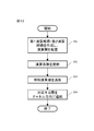
- FIG. 12 is a second flowchart of the first process of creating a neural network.
- the second flowchart of the first process of creating a neural network corresponds to the one in which step S43 is added between steps S12 and S13 in the first flowchart of the first process of creating a neural network. Therefore, the description of steps S41, S42, and S44, which are common to the first flowchart of the neural network creation process, will be omitted.
- the computer inputs the teacher data into the first calculation path P1 and the second calculation path P2, respectively, and the first calculation path P1 and the second calculation path so that the error between the output value and the correct answer shown in the teacher data becomes small.
- the operation coefficient of the combination in P2 is updated (step S43).
- the computer since the arithmetic layer included in the first arithmetic path P1 and the arithmetic layer included in the second arithmetic path P2 are not connected in the channel direction, the computer updates the arithmetic coefficients in the first arithmetic path P1 and the second arithmetic path P1 and the second. It can be executed independently for the calculation path P2.
- FIG. 13 is a third flowchart of the first process of creating a neural network.
- the third flowchart of the first process of creating a neural network corresponds to the one in which step S52 is added between steps S11 and S12 in the first flowchart of the first process of creating a neural network. Therefore, the description of steps S51, S53, and S54 common to the first flowchart of the neural network creation first process will be omitted. Further, since the process of step S52 is the same as the process of step S43 in the second flowchart of the first process of creating the neural network, the description of step S52 will be omitted.
- FIG. 14 is a schematic diagram showing the configuration of a camera equipped with an arithmetic unit.
- the arithmetic unit is a microcontroller 4 mounted on the camera 2.
- the camera 2 is an example of an image pickup apparatus, and includes an image sensor 3, a microcontroller 4, and a lens 5.
- the image sensor 3 is an example of an image pickup device, and converts light from a subject focused by the lens 5 into image data.
- the microcontroller 4 is an integrated circuit that integrates a processor, a memory, and an input / output interface. The microcontroller 4 executes an operation based on the image data input from the image sensor 3 and outputs a signal indicating a region in the image data to be the target of autofocus.
- the microcontroller 4 operates as a focusing control unit and outputs a focusing control signal for controlling the lens 5 so as to focus on a predetermined region represented by image data.
- the lens 5 is an example of an optical system, and the light from the subject is focused on the image sensor 3.
- the lens 5 has an autofocus mechanism 51, and the autofocus mechanism 51 focuses the lens 5 on the subject based on the focusing control signal output from the microcontroller 4.
- the arithmetic unit according to the present embodiment can implement a neural network such as ResNet that performs operations by a plurality of operation paths with a small cache memory.
- ResNet a neural network such as ResNet that performs operations by a plurality of operation paths with a small cache memory.
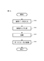
- FIG. 15 is a processing flowchart of a camera equipped with an arithmetic unit.
- the camera 2 starts the process of FIG. 15 in response to the detection of an operation instructing the execution of autofocus such as a half-press of a shutter button (not shown) by the user.
- the camera 2 may repeatedly execute the process of FIG. 15 while the operation instructing the execution of autofocus is detected.
- the image sensor 3 transmits image data corresponding to the focused light to the microcontroller 4 (step S101).
- the microcontroller 4 generates a first feature map and a second feature map having a common feature amount in the channel direction based on the received image data (step S102). Subsequently, the microcontroller 4 inputs the first feature map and the second feature map to the neural network, and executes an operation for identifying a region corresponding to the identification object included in the image data (step S103).
- the microcontroller 4 generates a focusing control signal for focusing on the region corresponding to the identification target object identified by the calculation, and transmits it to the autofocus mechanism 51.
- the autofocus mechanism 51 changes the position of the focusing lens included in the lens 5 based on the focusing control signal received from the microcontroller 4 (step S104). Whether or not the specified area of the image is in focus is determined by a method such as a contrast AF method or a phase difference AF method.
Landscapes
- Engineering & Computer Science (AREA)
- Theoretical Computer Science (AREA)
- Physics & Mathematics (AREA)
- Data Mining & Analysis (AREA)
- General Health & Medical Sciences (AREA)
- Biomedical Technology (AREA)
- Biophysics (AREA)
- Computational Linguistics (AREA)
- Life Sciences & Earth Sciences (AREA)
- Evolutionary Computation (AREA)
- Artificial Intelligence (AREA)
- Molecular Biology (AREA)
- Computing Systems (AREA)
- General Engineering & Computer Science (AREA)
- General Physics & Mathematics (AREA)
- Mathematical Physics (AREA)
- Software Systems (AREA)
- Health & Medical Sciences (AREA)
- Image Analysis (AREA)
Abstract
演算装置は、入力データに基づいて、チャネル方向の特徴量が共通する第1特徴マップおよび第2特徴マップを生成する生成部と、第1特徴マップが入力される第1領域および第2特徴マップが入力される第2領域をチャネル方向に有する入力層と、第1領域に対応する演算結果が出力される第3領域および第2領域に対応する演算結果が出力される第4領域をチャネル方向に有する出力層とを備えるニューラルネットワークに演算を実行させる演算部と、を備え、第3領域は、第1領域および少なくとも第2領域の一部に結合されるとともに、第2領域から第3領域にいたる結合の演算係数は実質的にゼロに設定され、第4領域は、第2領域および少なくとも第1領域の一部に結合されるとともに、第1領域から第4領域にいたる結合の演算係数は実質的にゼロに設定される。
Description
本開示は、ニューラルネットワークを使用した演算装置、学習方法、およびニューラルネットワークの作成方法に関する。
従来、データの内容に基づく学習の結果に従って認識を行うニューラルネットワークの構成が提案されている(例えば非特許文献1を参照)。
Kaiming He et. al., "Deep Residual Learning for Image Recognition," arXiv:1512.03385, 2015
本開示にかかる演算装置は、入力データに基づいて、チャネル方向の特徴量が共通する第1特徴マップおよび第2特徴マップを生成する生成部と、第1特徴マップが入力される第1領域および第2特徴マップが入力される第2領域をチャネル方向に有する入力層と、第1領域に対応する演算結果が出力される第3領域および第2領域に対応する演算結果が出力される第4領域をチャネル方向に有する出力層とを備えるニューラルネットワークに演算を実行させる演算部と、を備え、第3領域は、第1領域および少なくとも第2領域の一部に結合されるとともに、第2領域から第3領域にいたる結合の演算係数は実質的にゼロに設定され、第4領域は、第2領域および少なくとも第1領域の一部に結合されるとともに、第1領域から第4領域にいたる結合の演算係数は実質的にゼロに設定される。
本開示にかかる学習方法は、入力データに基づいて、チャネル方向の特徴量が共通する第1特徴マップおよび第2特徴マップを生成する第1ステップと、第1特徴マップが入力される第1領域および第2特徴マップが入力される第2領域をチャネル方向に有する入力層と、第1領域に対応する演算結果が出力される第3領域および第2領域に対応する演算結果が出力される第4領域をチャネル方向に有する出力層とを備えるようニューラルネットワークを作成する第2ステップと、コンピュータが、入力データとして教師データをニューラルネットワークに入力し、入力層と出力層との結合の演算係数を更新する第3ステップと、を含み、第2ステップは、第3領域を第1領域および少なくとも第2領域の一部に結合するステップと、第4領域を第2領域および少なくとも第1領域の一部に結合するステップと、を含み、第3ステップは、第2領域から第3領域にいたる結合の演算係数および第1領域から第4領域にいたる結合の演算係数が実質的にゼロになるよう、演算係数を更新するステップを含む。
本開示にかかる学習方法は、入力データに基づいて、チャネル方向の特徴量が共通する第1特徴マップおよび第2特徴マップを生成する第1ステップと、第1特徴マップが入力される第1領域および第2特徴マップが入力される第2領域をチャネル方向に有する入力層と、第1領域に対応する演算結果が出力される第3領域および第2領域に対応する演算結果が出力される第4領域をチャネル方向に有する出力層とを備えるようニューラルネットワークを作成する第2ステップと、コンピュータが、入力データとして教師データをニューラルネットワークに入力し、入力層と出力層との結合の演算係数を更新する第3ステップと、を含み、第2ステップは、第3領域を第1領域および少なくとも第2領域の一部に結合するステップと、第4領域を第2領域および少なくとも第1領域の一部に結合するステップと、を含み、第3ステップは、第2領域から第3領域にいたる結合の演算係数および第1領域から第4領域にいたる結合の演算係数を実質的にゼロに維持しながら、その他の結合の演算係数を更新するステップを含む。
本開示にかかるニューラルネットワークの作成方法は、入力された特徴マップの特徴量に対し演算係数を用いて所定の演算を実行した結果を出力する演算層をそれぞれ1以上備えるように第1演算経路および第2演算経路を作成するとともに、同一の演算を実行する演算層の位置が第1演算経路および第2演算経路において対応する位置となるように各演算層を配置するステップと、第1演算経路において第2演算経路に配置された演算層に対応する演算層が配置されていない位置、および、第2演算経路において第1演算経路に配置された演算層に対応する演算層が配置されていない位置に、対応する位置に配置された演算層と同一の演算を実行する補助演算層を追加するステップと、少なくともいずれか一方に補助演算層を追加された第1演算経路および第2演算経路に、それぞれ教師データを入力して演算層の演算係数を更新するステップと、演算係数が更新された第1演算経路および第2演算経路において対応するそれぞれの層をチャネル方向に連結するステップと、を含む。
本開示にかかるニューラルネットワークの作成方法は、入力された特徴マップの特徴量に対し演算係数を用いて所定の演算を実行した結果を出力する演算層をそれぞれ1以上備えるように第1演算経路および第2演算経路を作成するとともに、同一の演算を実行する演算層の位置が第1演算経路および第2演算経路において対応する位置となるように各演算層を配置するステップと、第1演算経路および第2演算経路にそれぞれ教師データを入力して演算層の演算係数を更新するステップと、第1演算経路において第2演算経路に配置された演算層に対応する演算層が配置されていない位置、および、第2演算経路において第1演算経路に配置された演算層に対応する演算層が配置されていない位置に、対応する位置に配置された演算層と同一の演算を実行する補助演算層を追加するステップと、少なくともいずれか一方に補助演算層が追加された第1演算経路および第2演算経路において対応するそれぞれの層をチャネル方向に連結するステップと、を含む。
以下、図面を参照して演算装置、学習方法、およびニューラルネットワークの作成方法について詳細に説明する。ただし、本発明は図面または以下に記載される実施形態には限定されないことを理解されたい。
図1はコンピュータの概略構成を示す模式図であり、図2はプロセッサの機能ブロック図である。
本実施形態において、演算装置の一例であるコンピュータ1は、所定の入力データに基づいて特徴マップを生成し、特徴マップをニューラルネットワークに入力して演算結果を出力する。そのために、コンピュータ1は、入出力インタフェース11と、メモリ12と、プロセッサ13とを備える。
入出力インタフェース11は、コンピュータ1が処理すべきデータを受け付け、または、コンピュータ1により処理されたデータを出力するためのインタフェース回路を有する。入出力インタフェース11は、例えばコンピュータ1を通信ネットワークに接続するための通信インタフェース回路、またはコンピュータ1をキーボード、ディスプレイといった各種周辺機器と接続するための周辺機器インタフェース回路を含む。入出力インタフェース11は、所定のデータの入力を受け付けて、処理結果を出力する。
メモリ12は記憶部の一例であり、例えば、半導体メモリ、磁気ディスク装置および光ディスク装置のうちの少なくとも1つを有する。メモリ12は、プロセッサ13による処理に用いられるドライバプログラム、オペレーティングシステムプログラム、アプリケーションプログラム、データ等を記憶する。例えば、メモリ12はアプリケーションプログラムとして、本開示の演算処理を実現するためのコンピュータプログラムを記憶する。また、メモリ12はデータとして、ニューラルネットワークを規定するためのパラメータ群(層数、層構成、カーネル、重み係数等)を記憶する。各種プログラムは、コンピュータ読み取り可能な可搬型記録媒体から、公知のセットアッププログラム等を用いてメモリ12にインストールされてよい。コンピュータ読み取り可能な可搬型記録媒体とは、例えばCD-ROM(Compact Disc Read-Only Memory)、DVD-ROM(DVD Read-Only Memory)等である。
プロセッサ13は、1以上のプロセッサおよびその周辺回路を備える。プロセッサ13は、コンピュータ1の全体的な動作を統括的に制御する処理回路であり、例えば、CPU(Central Processing Unit)である。プロセッサ13は、大量の定型的演算を並列に処理可能なGPU(Graphics Processing Unit)を有してもよい。プロセッサ13は、コンピュータ1の各種処理がメモリ12に記憶されているプログラム等に基づいて適切な手段で実行されるように、入出力インタフェース11等の動作を制御する。プロセッサ13は、メモリ12に記憶されているプログラム(オペレーティングシステムプログラム、ドライバプログラム、アプリケーションプログラム等)に基づいて処理を実行する。また、プロセッサ13は、複数のプログラム(アプリケーションプログラム等)を並列に実行することができる。
図2に示すように、プロセッサ13は、入力された入力データに基づいて特徴マップを生成するための生成部131と、ニューラルネットワークNN1による演算を実行するための演算処理部132を有する。演算処理部132は、プロセッサ13が有するプロセッサ上で実行されるプログラムによって実装される機能モジュールである。あるいは、演算処理部132は、独立した集積回路、マイクロプロセッサ、またはファームウェアとしてコンピュータ1に実装されてもよい。
図3は、生成部131による特徴マップの生成を説明する図である。生成部131は、入力データIDに基づいて、第1特徴マップFM1および第2特徴マップFM2を生成する。入力データIDは、例えば画素ごとにRGBの対応値を有する画像データである。第1特徴マップFM1および第2特徴マップFM2において、チャネル(C)方向の特徴量は共通している。すなわち、第1特徴マップFM1および第2特徴マップFM2において、対応するチャネルにおける特徴量は同一である。
生成部131は、入力データIDに対し、畳み込み演算、転置畳み込み演算、プーリング演算、活性化演算といった所定の演算を行うことにより、第1特徴マップFM1および第2特徴マップFM2を生成する。生成部131は、例えば画像データである入力データIDに対し、RGBのそれぞれについて画素ごとに畳み込み演算を実行することにより、第1特徴マップFM1および第2特徴マップFM2を生成する。また、生成部131は、入力データIDと同一のデータを、第1特徴マップFM1および第2特徴マップFM2として生成してもよい。
図4は、ニューラルネットワークNN1の構造を示す模式図である。
ニューラルネットワークNN1には、上述の生成部131により入力データIDに基づいて生成された第1特徴マップFM1および第2特徴マップFM2が入力される。そして、ニューラルネットワークNN1は、第1特徴マップFM1および第2特徴マップFM2に対し、畳み込み演算、転置畳み込み演算、プーリング演算、活性化演算のうち少なくとも1つを行い、出力データODを出力する。ニューラルネットワークNN1は、検出対象となる物体が表わされた複数の画像、および、各画像上における物体の位置、種類等を示す情報を教師データとして用いて、誤差逆伝搬法に従って学習される。ニューラルネットワークNN1は、例えば、畳み込みの演算経路とスキップコネクションの演算経路とを有するResNetである。ニューラルネットワークNN1は、例えば画像データの入力に基づいて、画像データに表わされる物体を検出する。
ニューラルネットワークNN1は、入力層ILと出力層OLとを備える。入力層ILは、チャネル方向に、第1領域R1および第2領域R2を有する。第1領域R1には、入力データIDに基づいて生成された第1特徴マップFM1が入力される。第2領域R2には、入力データIDに基づいて生成された第2特徴マップFM2が入力される。
出力層OLは、チャネル方向に、第3領域R3および第4領域R4を有する。第3領域R3は、第1領域R1と結合される。また、第3領域R3は、第2領域R2の少なくとも一部に結合される。このとき、第2領域R2から第3領域R3にいたる結合の演算係数は、実質的にゼロに設定される。
第4領域R4は、第2領域R2と結合される。また、第4領域R4は、第1領域R1の少なくとも一部に結合される。このとき、第1領域R1から第4領域R4にいたる結合の演算係数は、実質的にゼロに設定される。
ニューラルネットワークNN1は、第3領域R3の出力および第4領域R4の出力に基づいて出力データODを生成し、出力する。
本明細書において、結合の演算係数が実質的にゼロに設定されるとは、前の層の特徴量が後の層における演算の結果に影響を与えないように演算係数が設定されることをいい、詳細は後述する。
ニューラルネットワークNN1は、入力層ILと出力層OLとの間に、少なくとも1つ、好ましくは複数の中間層を有していてもよい。
図5は、ニューラルネットワーク作成第1処理の第1フローチャートであり、図6(a)-(c)は、ニューラルネットワーク作成第1処理におけるニューラルネットワークの状態を示す図である。コンピュータは、図5に示す各ステップの処理を実行することにより、ニューラルネットワークNN1を作成することができる。
まず、コンピュータは、演算層をそれぞれ1以上備える第1演算経路P1および第2演算経路P2を作成する。そして、同一の演算を実行する演算層の位置が第1演算経路P1および第2演算経路P2において対応する位置となるように各演算層を配置する(ステップS11)。
図6Aは、3つの演算層L11-L13を有する第1演算経路P1と、2つの演算層L21-L22を有する第2演算経路P2とが作成され、各演算層が配置された状態を示している。
第1演算経路P1は、畳み込み演算を実行する演算層L11およびL12と、活性化演算を実行する演算層L13とを有する。第1演算経路P1には、W×H×Ciの次元を有する第1特徴マップFM1が入力される(Wは幅、Hは高さ、Cはチャネルを表す)。演算層L11は、入力された第1特徴マップFM1に対して、例えば3×3のカーネルを用いた畳み込み演算を実行し、W×H×Cmの次元を有する特徴マップを出力する。演算層L12は、演算層L11から出力された特徴マップに対して、例えば3×3のカーネルを用いた畳み込み演算を実行し、W×H×Coの次元を有する特徴マップを出力する。演算層L13は、演算層L12から出力された特徴マップに対して、例えばReLU関数による活性化演算を実行し、W×H×Coの次元を有する特徴マップを出力する。
第2演算経路P2は、畳み込み演算を実行する演算層L21およびL22を有する。第2演算経路P2には、W×H×Ciの次元を有する第2特徴マップFM2が入力される。演算層L21は、入力された第2特徴マップFM2に対して、例えば3×3のカーネルを用いた畳み込み演算を実行し、W×H×Crの次元を有する特徴マップを出力する。演算層L22は、演算層L21から出力された特徴マップに対して、例えば1×1のカーネルを用いた畳み込み演算を実行し、W×H×Coの次元を有する特徴マップを出力する。
第1演算経路P1の出力および第2演算経路の出力の和は、ニューラルネットワークNN1の出力として次の処理に渡される。
次に、コンピュータは、第1演算経路P1において第2演算経路P2に配置された演算層に対応する演算層が配置されていない位置、および、第2演算経路において第1演算経路P1に配置された演算層に対応する演算層が配置されていない位置に、補助演算層を追加する(ステップS12)。図6Aの例では、第1演算経路P1において、第2演算経路P2に配置された演算層L22に対応する演算層は配置されていない。また、第2演算経路P2において、第1演算経路P1に配置された演算層L11および演算層L13に対応する演算層は配置されていない。コンピュータは、図6Bに示すように、補助演算層FL1-FL3を追加する。補助演算層FL1は、演算層L11と同様の畳み込み演算を実行する演算層である。補助演算層FL2は、演算層L13と同様の活性化演算を実行する演算層である。補助演算層FL3は、演算層L22と同様の畳み込み演算を実行する演算層である。また、補助演算層FL1-3では、入力される特徴量と実質的に等しい特徴量を出力するように演算係数が設定される。
そして、コンピュータは、第1演算経路P1および第2演算経路P2において対応するそれぞれの層をチャネル方向に連結し(ステップS14)、ニューラルネットワークNN1を生成する。本開示において、「演算層をチャネル方向に連結する」とは、複数の演算層をチャネル方向に連続させて1つの演算層を構成することをいう。図6Cに示すように、対応する位置に配置された演算層L11および補助演算層FL1、演算層L12および演算層L21、演算層L13および補助演算層FL2、補助演算層FL3および演算層L22が、それぞれチャネル方向に連結される。第1演算経路P1および第2演算経路P2の対応する位置で連結された各層は、入力された特徴マップに対してそれぞれ同一の演算を実行する。例えば、演算層L11と補助演算層FL1とが連結された層は、第1特徴マップFM1と第2特徴マップFM2とが連結された特徴マップに対して3×3のカーネルを用いた畳み込み演算を実行し、W×H×(Cm+Cr)の次元を有する特徴マップを出力する。
チャネル方向の連結において、第1演算経路P1の演算層の少なくとも一部は、第2演算経路P2の演算層の少なくとも一部に結合される。このとき、第1演算経路P1から第2演算経路P2にいたる結合の演算係数、および、第2演算経路P2から第1演算経路P1にいたる結合の演算係数は、実質的にゼロに設定される。
図7は演算経路における結合の第1の例を示す図であり、図8は演算経路における結合の第2の例を示す図である。図7、図8に示す例では、演算経路における各ノードは、チャネル方向に結合されている。
図7は、第1特徴マップFM1および第2特徴マップFM2と、連結された演算層L11および補助演算層FL1との結合の例を示している。演算層L11は第1演算経路P1に含まれ、第1特徴マップFM1が入力される。補助演算層FL1は第2演算経路P2に含まれ、第2特徴マップFM2が入力される。第1特徴マップFM1に含まれる一部のチャネルは、第2特徴マップFM2にも含まれている。演算層L11および補助演算層FL1は、入力層ILに対応する。
演算層L11の各チャネルCm1-Cm4には、第1特徴マップFM1および第2特徴マップFM2の各チャネルCi1-Ci16が全結合される。また、補助演算層FL1の各チャネルCr1-Cr8には、第1特徴マップFM1および第2特徴マップFM2の各チャネルCi1-Ci16が全結合される。
演算層L11の各チャネルCm1-Cm4と第2特徴マップFM2の各チャネルのうち第1特徴マップFM1に含まれないチャネルCi11-Ci16との結合の演算係数は、実質的にゼロに設定される。補助演算層FL1の各チャネルCr1-Cr8と、対応するチャネルCi9-Ci16との結合以外の結合の演算係数は、実質的にゼロに設定される。このように演算係数を設定することにより、一部のチャネル(Ci9-Ci10)が共通する第1特徴マップFM1および第2特徴マップFM2を、第1演算経路P1および第2演算経路P2に分岐させることができる。また、補助演算層FL1は、第2演算経路の後続の演算層に対して、入力された第2特徴マップFM2を変更せずに出力することができる。
演算層で実行される畳み込み演算は、以下の式1により一般的に表現される。

式1において、演算層L11および補助演算層FL1で実行される畳み込み演算に用いられる演算係数であるウェイトWは、以下に示す式2のように設定される。

すなわち、演算層L11における結合のウェイトはWf1であり、補助演算層FL1における結合のウェイトはWh1である。Wf1のうち、第1特徴マップFM1との結合のウェイトは学習により更新され、第2特徴マップFM2のうち第1特徴マップFM1に含まれないチャネルとの結合のウェイトは実質的にゼロになるよう設定される。
また、Wh1のうち、第1特徴マップFM1のうち第2特徴マップFM2に含まれないチャネルとの結合のウェイトは、実質的にゼロになるよう設定され、第2特徴マップFM2との結合のウェイトは、第2特徴マップFM2と補助演算層FL1との対応するチャネルどうし(例えばCi21とCr1)の結合のウェイトが所定値(例えば1)、他のチャネルとの結合のウェイトが実質的に0となるよう予め設定され、学習により更新されない。
Wh1を以下に示す式3のように設定することにより、補助演算層FL1における畳み込み演算において、第2特徴マップFM2と等しい値を補助演算層FL1から出力させることができる。なお、式3において、δはクロネッカーのデルタである。また、式3において、rおよびsの値域は-(k-1)/2~(k-1)/2であり、cr>coである。

図8は、連結された演算層L11および補助演算層FL1と、連結された演算層L12および演算層L21との結合の例を示している。演算層L11および演算層L12は第1演算経路P1に含まれる。補助演算層FL1および演算層L21は第2演算経路P2に含まれる。演算層L12および演算層L21は、入力層ILと出力層OLとの間の中間層に該当する。
演算層L12の各チャネルCo1、Co2には、演算層L11の各チャネルCm1-Cm4および補助演算層FL1の各チャネルCr1-Cr8が全結合される。演算層L12の各チャネルCo1、Co2と補助演算層FL1の各チャネルCr1-Cr8との結合の演算係数は、実質的にゼロに設定される。また、演算層L21の各チャネルCr1-Cr8には、演算層L11の各チャネルCm1-Cm4および補助演算層FL1の各チャネルCr1-Cr8が全結合される。演算層L21の各チャネルCr1-Cr8と演算層L11の各チャネルCm1-Cm4との結合の演算係数は、実質的にゼロに設定される。
このとき、式1における演算係数であるウェイトWは、以下に示す式4のように設定される。

すなわち、演算層L11と演算層L12との結合のウェイトはWf2であり、演算層L11と演算層L21との結合のウェイト、および、補助演算層FL1と演算層L12との結合のウェイトは0であり、補助演算層FL1と演算層L21との結合のウェイトはWh2である。Wf2は、演算層L11と演算層L12とがチャネル方向に全結合されるように設定され、学習により更新される。Wh2は、予め設定され、学習により更新されない。
また、補助演算層FL3と演算層L22とが連結された演算層による畳み込み演算に用いられるウェイトWを以下に示す式5のように設定することにより、補助演算層FL3の出力と演算層L22の出力との和演算を実行することができる。すなわち、補助演算層FL3の演算に用いられるウェイトをWh3とし、演算層L22の演算に用いられるウェイトをWf3とする。式5において、λは、補助演算層FL3の出力と演算層L22の出力との和に要求されるウェイト比に応じて設定される係数テンソルである。λの値は1であってよい。

図9は、補助演算層FL2における活性化演算の概要を示す図である。
補助演算層FL2は、演算層L13と同様の活性化演算を実行し、演算係数が実質的にゼロに設定される。活性化演算について演算係数が実質的にゼロとするため、補助演算層FL2は、入力側から順に、オフセット演算層FL21と、活性化演算層FL22と、逆オフセット演算層FL23とを有する。
補助演算層FL2は、活性化演算層FL22による活性化演算の直前にオフセット演算層FL21によるオフセット演算を実行し、活性化演算の直後に逆オフセット演算層FL23による逆オフセット演算を実行する。オフセット演算とは、入力値を活性化演算の前後で値が実質的に変化しない値域に変換する演算である。また、逆オフセット演算とは、オフセット演算により変換された値を元の入力値に変換する演算である。
活性化演算層FL22がReLU関数による活性化演算を実行する場合、オフセット演算層FL21は、入力値に所定の正の値を加算することによりオフセット演算を実行することができる。このとき、逆オフセット演算層FL23は、オフセット演算により加算された所定の正の値を入力値から減算することにより逆オフセット演算を実行することができる。
また、オフセット演算層FL21は、例えば入力値に対するバッチ正規化を行うことにより、入力値の正規化を行ってもよい。ミニバッチにおける平均をμ、標準偏差をσとするとき、σを1、μを十分大きな値となるように正規化を行うことにより、ReLU関数による活性化演算に対するオフセット演算を実行することができる。また、μを0、σを十分大きな値となるように正規化を行うことにより、シグモイド関数による活性化演算に対するオフセット演算を実行することができる。逆オフセット演算層FL23は、オフセット演算層FL21における演算を打ち消す演算を実行する。
オフセット演算層FL21は、前の演算層において、畳み込み演算のバイアスを1以外の値に設定することにより実装されてもよい。同様に、逆オフセット演算層FL23は、後の演算層において、畳み込み演算のバイアスを1以外の値に設定することにより実装されてもよい。
また、活性化演算層FL22がシグモイド関数による活性化演算を実行する場合、オフセット演算層FL21は、入力値をそのまま出力してもよい。この場合、逆オフセット演算層FL23は、シグモイド関数の逆関数による演算を実行し、元の入力値を求める。
ニューラルネットワークNN1は、転置畳み込み演算を実行する演算層を有してもよい。転置畳み込み演算を実行する演算層に対応する補助演算層において、畳み込み演算の場合と同様に、対応するチャネルの特徴量に対するウェイト以外が0となるよう設定される。これにより、転置畳み込み演算を実行する演算層に対応する補助演算層は、入力された特徴マップをそのまま出力することができる。
ニューラルネットワークNN1は、プーリング演算を実行する演算層を有してもよい。プーリング演算を実行する演算層に対応する補助演算層では、プーリング演算における対象領域のサイズに応じたストライド(例えば2×2プーリングの場合、ストライド2)で1×1のカーネルを用いた畳み込み演算を実行する。
ニューラルネットワークNN1は、バッチ正規化演算を実行する演算層を有してもよい。バッチ正規化演算を実行する演算層に対応する補助演算層では、バッチ正規化演算において算出されたμ、σを、実際の値にかかわらずそれぞれ0、1とすることにより、入力された特徴マップをそのまま出力することができる。
ニューラルネットワークNN1では、第1演算経路P1に含まれる所定サイズ(例えば3×3)のカーネルを用いた畳み込み演算を実行する演算層と第2演算経路P2に含まれる異なるサイズ(例えば5×5)のカーネルを用いた畳み込み演算を実行する演算層が結合されてもよい。この場合、結合された演算層では、大きい方のカーネルを用いた畳み込み演算が実行され、小さい方のカーネルを用いる畳み込み演算が行われる演算経路では、カーネルの外側における演算係数がゼロに設定される。同様に、ダイレートサイズの異なるカーネルを用いた畳み込み演算を実行する演算層を結合することも可能である。この場合、結合された演算層ではダイレートサイズが大きいカーネルを使用し、ダイレートサイズが小さいカーネルを用いる畳み込み演算では、不要な演算係数がゼロに設定される。
以上の処理によって作成されたニューラルネットワークNN1において、演算層L11に対応するチャネル方向の領域は第1領域R1に対応し、補助演算層FL1に対応するチャネル方向の領域は第2領域R2に対応する。そして、チャネル方向に連結された演算層L11および補助演算層FL1は、入力層ILに対応する。また、ニューラルネットワークNN1において、補助演算層FL3に対応するチャネル方向の領域は第3領域R3に対応し、演算層L22に対応するチャネル方向の領域は第4領域R4に対応する。そして、チャネル方向に連結された補助演算層FL3および演算層L22は、出力層OLに対応する。
図7、8に示すように、補助演算層FL3は、第1特徴マップFM1および第2特徴マップFM2に結合され、第2特徴マップFM2との結合の演算係数は実質的にゼロに設定されている。同様に、演算層L22は、第1特徴マップFM1および第2特徴マップFM2に結合され、第1特徴マップFM1との結合の演算係数は実質的にゼロに設定されている。
複数の演算経路を有するニューラルネットワークをコンピュータに実装するには、演算経路ごとに演算処理を実行する必要がある。そのため、汎用的なFPGA(Field-Programmable Gate Array)または並列計算エンジンにおけるこのようなニューラルネットワークの実装は、複雑なものとなる。本実施形態のニューラルネットワークNN1は、複数の演算経路による演算を、連結された1つの演算経路によって実現することができるため、汎用的なFPGAまたは汎用計算エンジンに容易に実装することができる。また、本実施形態のニューラルネットワークNN1は、保持が必要な演算の中間結果データのデータ量を、複数の演算経路のまま実装する場合よりも削減することができる。
図10は、学習処理の動作フローチャートである。コンピュータは、図10に示す各ステップの処理を実行することにより、入力データに基づいてニューラルネットワークの演算係数を更新させ、入力データに基づく処理をニューラルネットワークに学習させることができる。
まず、コンピュータの生成部131は、教師データである入力データに基づいて、チャネル方向の特徴量が共通する第1特徴マップFM1および第2特徴マップFM2を生成する(ステップS21)。
次に、コンピュータは、入力層と出力層とを備えるニューラルネットワークを作成する(ステップS22)。入力層は、第1特徴マップFM1が入力される第1領域R1および第2特徴マップFM2が入力される第2領域R2をチャネル方向に有する。出力層は、第1領域R1に対応する演算結果が出力される第3領域R3および第2領域R2に対応する演算結果が出力される第4領域R4をチャネル方向に有する。
続いて、コンピュータは、第1特徴マップFM1および第2特徴マップFM2をニューラルネットワークNN1に入力する。そして、コンピュータは、第3領域R3および第4領域R4における出力値と教師データに示される正解との誤差が小さくなるように、例えば勾配降下法および誤差逆伝搬法といった手法を用いて、入力層と出力層との結合の演算係数を更新し(ステップS23)、学習処理を終了する。
ステップS23において、コンピュータは、第2領域R2から第3領域R3にいたる結合の演算係数および第1領域R1から第4領域R4にいたる結合の演算係数が実質的にゼロになるよう、演算係数を更新する。
また、ステップS23において、コンピュータは、第2領域R2から第3領域R3にいたる結合の演算係数および第1領域R1から第4領域R4にいたる結合の演算係数が実質的にゼロに維持しながら、その他の結合の演算係数を更新してもよい。
図11は、ニューラルネットワーク作成第2処理のフローチャートである。コンピュータは、図10に示す学習処理におけるステップS22が呼び出されるたびに図11に示されるフローチャートを実行する。
まず、コンピュータは、第1特徴マップFM1が入力される第1領域R1および第2特徴マップFM2が入力される第2領域R2をチャネル方向に有する入力層を作成する(ステップS31)。続いて、コンピュータは、第3領域R3および第4領域R4をチャネル方向に有する出力層を作成する(ステップS32)。
次に、コンピュータは、第3領域R3を第1領域R1および少なくとも第2領域R2の一部に結合する(ステップS33)。続いて、コンピュータは、第4領域R4を第2領域R2および少なくとも第1領域R1の一部に結合し(ステップS34)、ニューラルネットワーク作成第2処理を終了する。コンピュータは、ステップS31およびステップS32を逆の順序で実行してもよい。また、コンピュータは、ステップS33およびステップS34を逆の順序で実行してもよい。このように作成されたニューラルネットワークは、図4に表されるニューラルネットワークNN1に相当する。
図12は、ニューラルネットワーク作成第1処理の第2フローチャートである。ニューラルネットワーク作成第1処理の第2フローチャートは、ニューラルネットワーク作成第1処理の第1フローチャートにおけるステップS12とステップS13との間にステップS43を追加したものに相当する。そのため、ニューラルネットワーク作成処理の第1フローチャートと共通するステップS41、S42、S44については説明を省略する。
コンピュータは、第1演算経路P1および第2演算経路P2にそれぞれ教師データを入力し、出力値と教師データに示される正解との誤差が小さくなるように、第1演算経路P1および第2演算経路P2における結合の演算係数を更新する(ステップS43)。このとき、第1演算経路P1に含まれる演算層および第2演算経路P2に含まれる演算層はチャネル方向に連結されていないため、コンピュータは、演算係数の更新を第1演算経路P1および第2演算経路P2について独立に実行することができる。
図13は、ニューラルネットワーク作成第1処理の第3フローチャートである。ニューラルネットワーク作成第1処理の第3フローチャートは、ニューラルネットワーク作成第1処理の第1フローチャートにおけるステップS11とステップS12との間にステップS52を追加したものに相当する。そのため、ニューラルネットワーク作成第1処理の第1フローチャートと共通するステップS51、S53、S54については説明を省略する。また、ステップS52の処理は、ニューラルネットワーク作成第1処理の第2フローチャートにおけるステップS43の処理と同様であるので、ステップS52についても説明を省略する。
次に、演算装置をカメラに搭載した例について説明する。図14は、演算装置を搭載するカメラの構成を示す模式図である。
本実施形態にかかる演算装置は、カメラ2に搭載されるマイクロコントローラ4である。カメラ2は、撮像装置の一例であり、イメージセンサ3、マイクロコントローラ4およびレンズ5を備える。イメージセンサ3は、撮像素子の一例であり、レンズ5で集光された被写体からの光を画像データに変換する。マイクロコントローラ4は、プロセッサ、メモリ、入出力インタフェースを集積した集積回路である。マイクロコントローラ4は、イメージセンサ3から入力された画像データに基づいて演算を実行し、オートフォーカスの対象とすべき画像データ中の領域を示す信号を出力する。また、マイクロコントローラ4は、合焦制御部として動作し、画像データに表される所定の領域に合焦するようレンズ5を制御する合焦制御信号を出力する。レンズ5は、光学系の一例であり、被写体からの光をイメージセンサ3に集光させる。レンズ5は、オートフォーカス機構51を有し、オートフォーカス機構51は、マイクロコントローラ4から出力される合焦制御信号に基づいてレンズ5を被写体に合焦させる。
本実施形態にかかる演算装置は、複数の演算経路による演算を行うResNetのようなニューラルネットワークを、少ないキャッシュメモリにより実装することができる。
図15は、演算装置を備えたカメラの処理フローチャートである。カメラ2は、ユーザによる不図示のシャッターボタンの半押しなどのオートフォーカス実行を指示する動作の検出に応じて、図15の処理を開始する。カメラ2は、オートフォーカス実行を指示する動作が検出されている間、図15の処理を繰り返し実行してもよい。
まず、イメージセンサ3は、集光された光に応じた画像データをマイクロコントローラ4に送信する(ステップS101)。
次に、マイクロコントローラ4は、受信した画像データに基づいて、チャネル方向の特徴量が共通する第1特徴マップおよび第2特徴マップを生成する(ステップS102)。続いて、マイクロコントローラ4は、第1特徴マップおよび第2特徴マップをニューラルネットワークに入力し、画像データに含まれる識別対象物に対応する領域を識別する演算を実行させる(ステップS103)。
続いて、マイクロコントローラ4は、演算により識別された識別対象物に対応する領域に合焦させるための合焦制御信号を生成し、オートフォーカス機構51に送信する。オートフォーカス機構51は、マイクロコントローラ4より受信した合焦制御信号に基づいて、レンズ5に含まれる合焦レンズの位置を変更する(ステップS104)。画像の特定された領域に焦点が合っているか否かは、コントラストAF方式、位相差AF方式などの方式により判定される。
当業者は、本開示の精神および範囲から外れることなく、種々の変更、置換および修正をこれに加えることが可能であることを理解されたい。
1 コンピュータ
131 生成部
132 演算処理部
NN1 ニューラルネットワーク
131 生成部
132 演算処理部
NN1 ニューラルネットワーク
Claims (9)
- 入力データに基づいて、チャネル方向の特徴量が共通する第1特徴マップおよび第2特徴マップを生成する生成部と、
前記第1特徴マップが入力される第1領域および前記第2特徴マップが入力される第2領域を前記チャネル方向に有する入力層と、前記第1領域に対応する演算結果が出力される第3領域および前記第2領域に対応する演算結果が出力される第4領域を前記チャネル方向に有する出力層とを備えるニューラルネットワークに演算を実行させる演算部と、を備え、
前記第3領域は、前記第1領域および少なくとも前記第2領域の一部に結合されるとともに、前記第2領域から前記第3領域にいたる結合の演算係数は実質的にゼロに設定され、
前記第4領域は、前記第2領域および少なくとも前記第1領域の一部に結合されるとともに、前記第1領域から前記第4領域にいたる結合の演算係数は実質的にゼロに設定される、
演算装置。 - 前記ニューラルネットワークは、前記入力層と前記出力層との間に少なくとも1つの中間層を備える、請求項1に記載の演算装置。
- 前記生成部は、前記入力データと同一のデータを前記第1特徴マップおよび前記第2特徴マップとして生成する、請求項1または2に記載の演算装置。
- 前記ニューラルネットワークは、畳み込み演算、転置畳み込み演算、プーリング演算、活性化演算のうち少なくとも1つを行う、請求項1-3のいずれか一項に記載の演算装置。
- 入力データに基づいて、チャネル方向の特徴量が共通する第1特徴マップおよび第2特徴マップを生成する第1ステップと、
前記第1特徴マップが入力される第1領域および前記第2特徴マップが入力される第2領域を前記チャネル方向に有する入力層と、前記第1領域に対応する演算結果が出力される第3領域および前記第2領域に対応する演算結果が出力される第4領域を前記チャネル方向に有する出力層とを備えるようニューラルネットワークを作成する第2ステップと、
コンピュータが、前記入力データとして教師データを前記ニューラルネットワークに入力し、前記入力層と前記出力層との結合の演算係数を更新する第3ステップと、を含み、
前記第2ステップは、
前記第3領域を前記第1領域および少なくとも前記第2領域の一部に結合するステップと、
前記第4領域を前記第2領域および少なくとも前記第1領域の一部に結合するステップと、を含み、
前記第3ステップは、前記第2領域から前記第3領域にいたる結合の演算係数および前記第1領域から前記第4領域にいたる結合の演算係数が実質的にゼロになるよう、演算係数を更新するステップを含む、
学習方法。 - 入力データに基づいて、チャネル方向の特徴量が共通する第1特徴マップおよび第2特徴マップを生成する第1ステップと、
前記第1特徴マップが入力される第1領域および前記第2特徴マップが入力される第2領域を前記チャネル方向に有する入力層と、前記第1領域に対応する演算結果が出力される第3領域および前記第2領域に対応する演算結果が出力される第4領域を前記チャネル方向に有する出力層とを備えるようニューラルネットワークを作成する第2ステップと、
コンピュータが、前記入力データとして教師データを前記ニューラルネットワークに入力し、前記入力層と出力層との結合の演算係数を更新する第3ステップと、を含み、
前記第2ステップは、
前記第3領域を前記第1領域および少なくとも前記第2領域の一部に結合するステップと、
前記第4領域を前記第2領域および少なくとも前記第1領域の一部に結合するステップと、を含み、
前記第3ステップは、前記第2領域から前記第3領域にいたる結合の演算係数および前記第1領域から前記第4領域にいたる結合の演算係数を実質的にゼロに維持しながら、その他の結合の演算係数を更新するステップを含む、
学習方法。 - 入力された特徴マップの特徴量に対し演算係数を用いて所定の演算を実行した結果を出力する演算層をそれぞれ1以上備えるように第1演算経路および第2演算経路を作成するとともに、同一の演算を実行する前記演算層の位置が前記第1演算経路および前記第2演算経路において対応する位置となるように各演算層を配置するステップと、
前記第1演算経路において前記第2演算経路に配置された演算層に対応する演算層が配置されていない位置、および、前記第2演算経路において前記第1演算経路に配置された演算層に対応する演算層が配置されていない位置に、対応する位置に配置された演算層と同一の演算を実行する補助演算層を追加するステップと、
少なくともいずれか一方に前記補助演算層を追加された前記第1演算経路および前記第2演算経路に、それぞれ教師データを入力して前記演算層の前記演算係数を更新するステップと、
前記演算係数が更新された前記第1演算経路および前記第2演算経路において対応するそれぞれの層をチャネル方向に連結するステップと、
を含む、ニューラルネットワークの作成方法。 - 入力された特徴マップの特徴量に対し演算係数を用いて所定の演算を実行した結果を出力する演算層をそれぞれ1以上備えるように第1演算経路および第2演算経路を作成するとともに、同一の演算を実行する前記演算層の位置が前記第1演算経路および前記第2演算経路において対応する位置となるように各演算層を配置するステップと、
前記第1演算経路および前記第2演算経路にそれぞれ教師データを入力して前記演算層の前記演算係数を更新するステップと、
前記第1演算経路において前記第2演算経路に配置された演算層に対応する演算層が配置されていない位置、および、前記第2演算経路において前記第1演算経路に配置された演算層に対応する演算層が配置されていない位置に、対応する位置に配置された演算層と同一の演算を実行する補助演算層を追加するステップと、
少なくともいずれか一方に前記補助演算層が追加された前記第1演算経路および前記第2演算経路において対応するそれぞれの層をチャネル方向に連結するステップと、
を含む、ニューラルネットワークの作成方法。 - 前記補助演算層は、入力される特徴量と実質的に等しい値を出力するよう演算係数が設定された層である、請求項7または8に記載のニューラルネットワークの作成方法。
Applications Claiming Priority (2)
| Application Number | Priority Date | Filing Date | Title |
|---|---|---|---|
| JP2020115034 | 2020-07-02 | ||
| JP2020-115034 | 2020-07-02 |
Publications (1)
| Publication Number | Publication Date |
|---|---|
| WO2022004389A1 true WO2022004389A1 (ja) | 2022-01-06 |
Family
ID=79316101
Family Applications (1)
| Application Number | Title | Priority Date | Filing Date |
|---|---|---|---|
| PCT/JP2021/022886 Ceased WO2022004389A1 (ja) | 2020-07-02 | 2021-06-16 | 演算装置、学習方法、およびニューラルネットワークの作成方法 |
Country Status (1)
| Country | Link |
|---|---|
| WO (1) | WO2022004389A1 (ja) |
Citations (1)
| Publication number | Priority date | Publication date | Assignee | Title |
|---|---|---|---|---|
| JP2019159940A (ja) * | 2018-03-14 | 2019-09-19 | 株式会社Preferred Networks | 点群特徴抽出装置、点群特徴抽出方法及びプログラム |
-
2021
- 2021-06-16 WO PCT/JP2021/022886 patent/WO2022004389A1/ja not_active Ceased
Patent Citations (1)
| Publication number | Priority date | Publication date | Assignee | Title |
|---|---|---|---|---|
| JP2019159940A (ja) * | 2018-03-14 | 2019-09-19 | 株式会社Preferred Networks | 点群特徴抽出装置、点群特徴抽出方法及びプログラム |
Non-Patent Citations (2)
| Title |
|---|
| ALEX KRIZHEVSKY ; ILYA SUTSKEVER ; GEOFFREY E. HINTON: "ImageNet classification with deep convolutional neural networks", COMMUNICATIONS OF THE ACM, ASSOCIATION FOR COMPUTING MACHINERY, INC, UNITED STATES, vol. 60, no. 6, 24 May 2017 (2017-05-24), United States , pages 84 - 90, XP058339266, ISSN: 0001-0782, DOI: 10.1145/3065386 * |
| CHEN YUNPENG; FAN HAOQI; XU BING; YAN ZHICHENG; KALANTIDIS YANNIS; ROHRBACH MARCUS; SHUICHENG YAN; FENG JIASHI: "Drop an Octave: Reducing Spatial Redundancy in Convolutional Neural Networks With Octave Convolution", 2019 IEEE/CVF INTERNATIONAL CONFERENCE ON COMPUTER VISION (ICCV), IEEE, 27 October 2019 (2019-10-27), pages 3434 - 3443, XP033723723, DOI: 10.1109/ICCV.2019.00353 * |
Similar Documents
| Publication | Publication Date | Title |
|---|---|---|
| US11089201B2 (en) | Dual-core focusing image sensor, focusing control method for the same, and electronic device | |
| US11741348B2 (en) | Neural network circuit device, neural network, neural network processing method, and neural network execution program | |
| CN110858871B (zh) | 图像处理方法、图像处理装置、成像装置、镜头装置、存储介质、以及图像处理系统 | |
| US8683396B2 (en) | Determining source patterns for use in photolithography | |
| US20190139205A1 (en) | Method and apparatus for video super resolution using convolutional neural network with two-stage motion compensation | |
| JPWO2011158515A1 (ja) | 距離推定装置、距離推定方法、集積回路、コンピュータプログラム | |
| US20070172141A1 (en) | Image conversion device, image conversion method, and recording medium | |
| CN1953510A (zh) | 用于能够有效降低图像噪声的图像处理的方法和装置 | |
| JPWO2021140620A5 (ja) | ||
| US8908988B2 (en) | Method and system for recovering a code image including blurring | |
| US20100239125A1 (en) | Digital image processing apparatus, tracking method, recording medium for storing computer program for executing the tracking method, and digital image processing apparatus adopting the tracking method | |
| Yu et al. | Impacts of cost functions on inverse lithography patterning | |
| CN103577520A (zh) | 目标检索装置、目标检索方法以及计算机可读取记录介质 | |
| JP2004274133A (ja) | 色収差補正装置および色収差補正方法、並びに色収差補正プログラム | |
| US12518440B2 (en) | Neural photofinisher digital content stylization | |
| JP4773680B2 (ja) | 情報処理装置および方法、プログラム記録媒体、並びにプログラム | |
| US7945148B2 (en) | Method and apparatus for correcting hand-shake in digital image processing apparatus | |
| JP7146461B2 (ja) | 画像処理方法、画像処理装置、撮像装置、プログラム、および、記憶媒体 | |
| US20150160580A1 (en) | Image forming apparatus including lens array optical system, image processing apparatus, program product, and computer-readable storage medium | |
| JP4906753B2 (ja) | 画像処理用ルックアップテーブル作成装置および画像処理用ルックアップテーブル作成方法 | |
| US8266554B2 (en) | Dynamic provisional decomposition of lithographic patterns having different interaction ranges | |
| TWI730467B (zh) | 影像轉換方法及影像轉換網路 | |
| US10460430B2 (en) | Image processing apparatus and method for detecting and reducing an unnecessary light component in an image based on multiple viewpoints | |
| Hyun et al. | Focus enhancement for image-based overlay metrology targets via generative models | |
| US20260128002A1 (en) | Training system, training method, dimming system, dimming method, computer-readable recording medium with stored program, and non-transitory computer program product |
Legal Events
| Date | Code | Title | Description |
|---|---|---|---|
| 121 | Ep: the epo has been informed by wipo that ep was designated in this application |
Ref document number: 21832264 Country of ref document: EP Kind code of ref document: A1 |
|
| NENP | Non-entry into the national phase |
Ref country code: DE |
|
| 122 | Ep: pct application non-entry in european phase |
Ref document number: 21832264 Country of ref document: EP Kind code of ref document: A1 |
|
| NENP | Non-entry into the national phase |
Ref country code: JP |