WO2021255776A1 - ばね用鋼線 - Google Patents
ばね用鋼線 Download PDFInfo
- Publication number
- WO2021255776A1 WO2021255776A1 PCT/JP2020/023360 JP2020023360W WO2021255776A1 WO 2021255776 A1 WO2021255776 A1 WO 2021255776A1 JP 2020023360 W JP2020023360 W JP 2020023360W WO 2021255776 A1 WO2021255776 A1 WO 2021255776A1
- Authority
- WO
- WIPO (PCT)
- Prior art keywords
- layer
- mass
- oxide layer
- spring
- steel wire
- Prior art date
- Legal status (The legal status is an assumption and is not a legal conclusion. Google has not performed a legal analysis and makes no representation as to the accuracy of the status listed.)
- Ceased
Links
Images


Classifications
-
- C—CHEMISTRY; METALLURGY
- C21—METALLURGY OF IRON
- C21D—MODIFYING THE PHYSICAL STRUCTURE OF FERROUS METALS; GENERAL DEVICES FOR HEAT TREATMENT OF FERROUS OR NON-FERROUS METALS OR ALLOYS; MAKING METAL MALLEABLE, e.g. BY DECARBURISATION OR TEMPERING
- C21D6/00—Heat treatment of ferrous alloys
- C21D6/002—Heat treatment of ferrous alloys containing Cr
-
- C—CHEMISTRY; METALLURGY
- C21—METALLURGY OF IRON
- C21D—MODIFYING THE PHYSICAL STRUCTURE OF FERROUS METALS; GENERAL DEVICES FOR HEAT TREATMENT OF FERROUS OR NON-FERROUS METALS OR ALLOYS; MAKING METAL MALLEABLE, e.g. BY DECARBURISATION OR TEMPERING
- C21D6/00—Heat treatment of ferrous alloys
- C21D6/005—Heat treatment of ferrous alloys containing Mn
-
- C—CHEMISTRY; METALLURGY
- C21—METALLURGY OF IRON
- C21D—MODIFYING THE PHYSICAL STRUCTURE OF FERROUS METALS; GENERAL DEVICES FOR HEAT TREATMENT OF FERROUS OR NON-FERROUS METALS OR ALLOYS; MAKING METAL MALLEABLE, e.g. BY DECARBURISATION OR TEMPERING
- C21D6/00—Heat treatment of ferrous alloys
- C21D6/008—Heat treatment of ferrous alloys containing Si
-
- C—CHEMISTRY; METALLURGY
- C21—METALLURGY OF IRON
- C21D—MODIFYING THE PHYSICAL STRUCTURE OF FERROUS METALS; GENERAL DEVICES FOR HEAT TREATMENT OF FERROUS OR NON-FERROUS METALS OR ALLOYS; MAKING METAL MALLEABLE, e.g. BY DECARBURISATION OR TEMPERING
- C21D9/00—Heat treatment, e.g. annealing, hardening, quenching or tempering, adapted for particular articles; Furnaces therefor
- C21D9/52—Heat treatment, e.g. annealing, hardening, quenching or tempering, adapted for particular articles; Furnaces therefor for wires; for strips ; for rods of unlimited length
- C21D9/525—Heat treatment, e.g. annealing, hardening, quenching or tempering, adapted for particular articles; Furnaces therefor for wires; for strips ; for rods of unlimited length for wire, for rods
-
- C—CHEMISTRY; METALLURGY
- C22—METALLURGY; FERROUS OR NON-FERROUS ALLOYS; TREATMENT OF ALLOYS OR NON-FERROUS METALS
- C22C—ALLOYS
- C22C38/00—Ferrous alloys, e.g. steel alloys
-
- C—CHEMISTRY; METALLURGY
- C22—METALLURGY; FERROUS OR NON-FERROUS ALLOYS; TREATMENT OF ALLOYS OR NON-FERROUS METALS
- C22C—ALLOYS
- C22C38/00—Ferrous alloys, e.g. steel alloys
- C22C38/02—Ferrous alloys, e.g. steel alloys containing silicon
-
- C—CHEMISTRY; METALLURGY
- C22—METALLURGY; FERROUS OR NON-FERROUS ALLOYS; TREATMENT OF ALLOYS OR NON-FERROUS METALS
- C22C—ALLOYS
- C22C38/00—Ferrous alloys, e.g. steel alloys
- C22C38/04—Ferrous alloys, e.g. steel alloys containing manganese
-
- C—CHEMISTRY; METALLURGY
- C22—METALLURGY; FERROUS OR NON-FERROUS ALLOYS; TREATMENT OF ALLOYS OR NON-FERROUS METALS
- C22C—ALLOYS
- C22C38/00—Ferrous alloys, e.g. steel alloys
- C22C38/18—Ferrous alloys, e.g. steel alloys containing chromium
-
- C—CHEMISTRY; METALLURGY
- C22—METALLURGY; FERROUS OR NON-FERROUS ALLOYS; TREATMENT OF ALLOYS OR NON-FERROUS METALS
- C22C—ALLOYS
- C22C38/00—Ferrous alloys, e.g. steel alloys
- C22C38/18—Ferrous alloys, e.g. steel alloys containing chromium
- C22C38/34—Ferrous alloys, e.g. steel alloys containing chromium with more than 1.5% by weight of silicon
-
- C—CHEMISTRY; METALLURGY
- C23—COATING METALLIC MATERIAL; COATING MATERIAL WITH METALLIC MATERIAL; CHEMICAL SURFACE TREATMENT; DIFFUSION TREATMENT OF METALLIC MATERIAL; COATING BY VACUUM EVAPORATION, BY SPUTTERING, BY ION IMPLANTATION OR BY CHEMICAL VAPOUR DEPOSITION, IN GENERAL; INHIBITING CORROSION OF METALLIC MATERIAL OR INCRUSTATION IN GENERAL
- C23C—COATING METALLIC MATERIAL; COATING MATERIAL WITH METALLIC MATERIAL; SURFACE TREATMENT OF METALLIC MATERIAL BY DIFFUSION INTO THE SURFACE, BY CHEMICAL CONVERSION OR SUBSTITUTION; COATING BY VACUUM EVAPORATION, BY SPUTTERING, BY ION IMPLANTATION OR BY CHEMICAL VAPOUR DEPOSITION, IN GENERAL
- C23C8/00—Solid state diffusion of only non-metal elements into metallic material surfaces; Chemical surface treatment of metallic material by reaction of the surface with a reactive gas, leaving reaction products of surface material in the coating, e.g. conversion coatings, passivation of metals
- C23C8/06—Solid state diffusion of only non-metal elements into metallic material surfaces; Chemical surface treatment of metallic material by reaction of the surface with a reactive gas, leaving reaction products of surface material in the coating, e.g. conversion coatings, passivation of metals using gases
- C23C8/08—Solid state diffusion of only non-metal elements into metallic material surfaces; Chemical surface treatment of metallic material by reaction of the surface with a reactive gas, leaving reaction products of surface material in the coating, e.g. conversion coatings, passivation of metals using gases only one element being applied
- C23C8/10—Oxidising
- C23C8/16—Oxidising using oxygen-containing compounds, e.g. water, carbon dioxide
- C23C8/18—Oxidising of ferrous surfaces
-
- C—CHEMISTRY; METALLURGY
- C21—METALLURGY OF IRON
- C21D—MODIFYING THE PHYSICAL STRUCTURE OF FERROUS METALS; GENERAL DEVICES FOR HEAT TREATMENT OF FERROUS OR NON-FERROUS METALS OR ALLOYS; MAKING METAL MALLEABLE, e.g. BY DECARBURISATION OR TEMPERING
- C21D2211/00—Microstructure comprising significant phases
- C21D2211/009—Pearlite
-
- C—CHEMISTRY; METALLURGY
- C21—METALLURGY OF IRON
- C21D—MODIFYING THE PHYSICAL STRUCTURE OF FERROUS METALS; GENERAL DEVICES FOR HEAT TREATMENT OF FERROUS OR NON-FERROUS METALS OR ALLOYS; MAKING METAL MALLEABLE, e.g. BY DECARBURISATION OR TEMPERING
- C21D8/00—Modifying the physical properties of ferrous metals or ferrous alloys by deformation combined with, or followed by, heat treatment
- C21D8/06—Modifying the physical properties of ferrous metals or ferrous alloys by deformation combined with, or followed by, heat treatment during manufacturing of rods or wires
-
- C—CHEMISTRY; METALLURGY
- C21—METALLURGY OF IRON
- C21D—MODIFYING THE PHYSICAL STRUCTURE OF FERROUS METALS; GENERAL DEVICES FOR HEAT TREATMENT OF FERROUS OR NON-FERROUS METALS OR ALLOYS; MAKING METAL MALLEABLE, e.g. BY DECARBURISATION OR TEMPERING
- C21D9/00—Heat treatment, e.g. annealing, hardening, quenching or tempering, adapted for particular articles; Furnaces therefor
- C21D9/52—Heat treatment, e.g. annealing, hardening, quenching or tempering, adapted for particular articles; Furnaces therefor for wires; for strips ; for rods of unlimited length
-
- F—MECHANICAL ENGINEERING; LIGHTING; HEATING; WEAPONS; BLASTING
- F16—ENGINEERING ELEMENTS AND UNITS; GENERAL MEASURES FOR PRODUCING AND MAINTAINING EFFECTIVE FUNCTIONING OF MACHINES OR INSTALLATIONS; THERMAL INSULATION IN GENERAL
- F16F—SPRINGS; SHOCK-ABSORBERS; MEANS FOR DAMPING VIBRATION
- F16F1/00—Springs
- F16F1/02—Springs made of steel or other material having low internal friction; Wound, torsion, leaf, cup, ring or the like springs, the material of the spring not being relevant
- F16F1/021—Springs made of steel or other material having low internal friction; Wound, torsion, leaf, cup, ring or the like springs, the material of the spring not being relevant characterised by their composition, e.g. comprising materials providing for particular spring properties
-
- F—MECHANICAL ENGINEERING; LIGHTING; HEATING; WEAPONS; BLASTING
- F16—ENGINEERING ELEMENTS AND UNITS; GENERAL MEASURES FOR PRODUCING AND MAINTAINING EFFECTIVE FUNCTIONING OF MACHINES OR INSTALLATIONS; THERMAL INSULATION IN GENERAL
- F16F—SPRINGS; SHOCK-ABSORBERS; MEANS FOR DAMPING VIBRATION
- F16F2224/00—Materials; Material properties
- F16F2224/02—Materials; Material properties solids
- F16F2224/0208—Alloys
Definitions
- This disclosure relates to steel wire for springs.
- An oil tempered wire (steel wire for spring) having an oxide layer on the outer peripheral surface is known for the purpose of ensuring lubricity during spring processing (for example, Japanese Patent Application Laid-Open No. 2004-052048 (Patent Document 1), Japanese Patent Application Laid-Open No. 2004-115859 (Patent Document 2), Japanese Patent Application Laid-Open No. 2017-115228 (Patent Document 3), and Japanese Patent Application Laid-Open No. 2018-012868 (Patent Document 4).
- the steel wire for a spring according to the present disclosure includes a steel main body portion having a linear shape and an oxide layer covering the outer peripheral surface of the main body portion.
- the steel constituting the main body consists of C (carbon) of 0.5% by mass or more and 0.7% by mass or less, Si (silicon) of 1.0% by mass or more and 2.5% by mass or less, and 0.2% by mass. It contains Mn (manganese) of% or more and 1.0% by mass or less and Cr (chromium) of 0.5% by mass or more and 2.0% by mass or less, and the balance is composed of Fe (iron) and unavoidable impurities.
- the structure of the steel that constitutes the main body is a pearlite structure.
- the thickness of the oxide layer is 2 ⁇ m or more and 5 ⁇ m or less.
- the oxide layer contains 60% by mass or more of Fe 3 O 4 .
- FIG. 1 is a schematic view showing the structure of a steel wire for a spring.
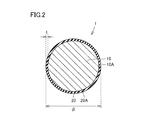
- FIG. 2 is a schematic cross-sectional view showing the structure of a steel wire for a spring.
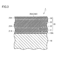
- FIG. 3 is a schematic cross-sectional view showing the structure of the oxide layer of the steel wire for spring.
- FIG. 4 is a flowchart showing an outline of a method for manufacturing a steel wire for a spring.
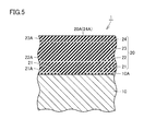
- FIG. 5 is a schematic cross-sectional view showing the structure of the oxide layer of the steel wire for spring according to the second embodiment.
- FIG. 5 is a photograph of the oxide layer by SEM.
- the spring steel wire which is an oil tempered wire a technique for ensuring lubricity at the time of processing into a spring is known by covering the outer peripheral surface with an oxide layer.
- the structure of the steel that constitutes the oil tempered wire is the tempered martensite structure.
- the tempered martensite structure is a structure containing a matrix of the martensite phase and fine carbides dispersed in the matrix.
- a hard drawn wire may be used as the steel wire for the spring.
- the structure of the steel that constitutes the hard drawn wire is a pearlite structure.
- Pearlite structure is a ferrite layer and a cementite (Fe 3 C) layer are alternately stacked tissue, the martensite tempering the sintered is significantly different tissues. Therefore, it is necessary to consider ensuring lubricity suitable for the pearlite structure for the hard drawn wire. Therefore, one of the purposes of the present disclosure is to provide a steel wire for a spring, which is a hard drawn wire having excellent lubricity during processing into a spring.
- the steel wire for a spring of the present disclosure includes a steel main body portion having a linear shape and an oxide layer covering the outer peripheral surface of the main body portion.
- the steel constituting the main body consists of C (carbon) of 0.5% by mass or more and 0.7% by mass or less, Si (silicon) of 1.0% by mass or more and 2.5% by mass or less, and 0.2% by mass. It contains Mn (manganese) of% or more and 1.0% by mass or less and Cr (chromium) of 0.5% by mass or more and 2.0% by mass or less, and the balance is composed of Fe (iron) and unavoidable impurities.
- the structure of the steel that constitutes the main body is a pearlite structure.
- the thickness of the oxide layer is 2 ⁇ m or more and 5 ⁇ m or less.
- the oxide layer contains 60% by mass or more of Fe 3 O 4 .
- the structure of the steel constituting the main body of the steel wire for spring of the present disclosure is a pearlite structure. That is, the steel wire for springs of the present disclosure is a hard drawn wire.
- the outer peripheral surface of the main body having this pearlite structure is covered with an oxide layer having a thickness of 2 ⁇ m or more and 5 ⁇ m or less.
- the oxide layer contains 60% by mass or more of Fe 3 O 4 . According to the study of the present inventor, when the oxide layer contains 60% by mass or more of Fe 3 O 4 , the oxide layer is suppressed from peeling from the main body having a pearlite structure during processing into a spring, and high lubrication is achieved. Sex is ensured.
- the oxide layer preferably contains 70% by mass or more of Fe 3 O 4, and more preferably 80% by mass or more of Fe 3 O 4 .
- Carbon (C) 0.5% by mass or more and 0.7% by mass or less Carbon is an element that has a great influence on the strength of steel. From the viewpoint of obtaining sufficient strength as a steel wire for springs, the carbon content needs to be 0.5% by mass or more. On the other hand, if the carbon content is high, the toughness may decrease and processing may become difficult. From the viewpoint of ensuring sufficient toughness, the carbon content should be 0.7% by mass or less. From the viewpoint of improving toughness and facilitating processing, the carbon content may be 0.6% by mass or less.
- Manganese (Mn) 0.2% by mass or more and 1% by mass or less
- Manganese is an element added as a deoxidizing agent in steel refining. In order to fulfill the function as a deoxidizing agent, the manganese content needs to be 0.2% by mass or more, and may be 0.5% by mass or more. On the other hand, excessive addition of manganese reduces toughness and workability in hot working. Therefore, the manganese content needs to be 1% by mass or less, and may be 0.9% by mass or less.
- Chromium (Cr) 0.5% by mass or more and 2% by mass or less Chromium functions as a carbide-forming element in steel and contributes to the miniaturization of the metal structure and the suppression of softening during heating due to the formation of fine carbides. From the viewpoint of ensuring such an effect, chromium needs to be added in an amount of 0.5% by mass or more. On the other hand, excessive addition of chromium causes a decrease in toughness. Therefore, the amount of chromium added needs to be 2% by mass or less. From the viewpoint of emphasizing toughness, the amount of chromium added may be 1.5% by mass or less, or 1% by mass or less.
- Phosphorus (P), sulfur (S), etc. are inevitably mixed in the steel in the manufacturing process of the steel constituting the steel wire for spring.
- Phosphorus and sulfur when present in excess, cause intergranular segregation and form inclusions, deteriorating the properties of steel. Therefore, the contents of phosphorus and sulfur are preferably 0.025% by mass or less, respectively.
- the total content of unavoidable impurities is preferably 0.3% by mass or less.
- the oxide layer may include a first Fe 3 O 4 layer and a second Fe 3 O 4 layer covering the outer peripheral surface of the first Fe 3 O 4 layer. ..
- the concentration of Si in the first Fe 3 O 4 layer may be higher than either the concentration of Si in the second Fe 3 O 4 layer or the concentration of Si in the main body.
- the presence of the first Fe 3 O 4 layer having a high concentration of Si between the second Fe 3 O 4 layer and the main body portion further suppresses the separation between the oxide layer and the main body portion.
- the oxide layer may further include a FeO layer located between the first Fe 3 O 4 layer and the main body portion.
- the formation of the Fe 2 O 3 layer, which is easily peeled off, can be suppressed by setting the oxidation state to the extent that the FeO layer is formed between the first Fe 3 O 4 layer and the main body portion.
- the FeO layer may cover the entire outer peripheral surface of the main body portion, but it is preferable that the FeO layer covers a part of the outer peripheral surface of the main body portion. It is preferable that the main body portion and the first Fe 3 O 4 layer are in contact with each other in the portion of the outer peripheral surface of the main body portion that is not covered by the FeO layer. By doing so, the peeling between the oxide layer and the main body portion is further suppressed.
- the concentration of Si in the first Fe 3 O 4 layer is 2.5% by mass or more and 6% by mass or less, and the concentration of Cr is 1.5% by mass or more and 3% by mass or less. May be good. By doing so, the peeling between the oxide layer and the main body portion is further suppressed.
- the thickness of the first Fe 3 O 4 layer may be 0.3 ⁇ m or more and 1.5 ⁇ m or less. By doing so, the peeling between the oxide layer and the main body portion is further suppressed.
- FIG. 1 is a schematic view showing the structure of a steel wire for a spring.
- FIG. 2 is a schematic cross-sectional view showing the structure of a steel wire for a spring.
- FIG. 2 is a cross-sectional view of a steel wire for a spring in a plane perpendicular to the longitudinal direction.
- the steel wire 1 for a spring in the present embodiment has a steel main body portion 10 having a linear shape and an oxide layer 20 covering the outer peripheral surface 10A of the main body portion 10. I have.
- the outer peripheral surface 20A of the oxide layer 20 is the outer peripheral surface of the spring steel wire 1.
- the diameter ⁇ of the spring steel wire 1 is, for example, 2.0 mm or more and 8.0 mm or less.
- the thickness t of the oxide layer 20 is 2 ⁇ m or more and 5 ⁇ m or less.
- the steel constituting the main body 10 is C of 0.5% by mass or more and 0.7% by mass or less, Si of 1% by mass or more and 2.5% by mass or less, and 0.2% by mass or more and 1% by mass or less. It contains Mn and Cr of 0.5% by mass or more and 2% by mass or less, and the balance is composed of Fe and unavoidable impurities.
- the steel constituting the main body 10 may have a component composition corresponding to JIS standard SWOSC-V.
- the steel constituting the main body 10 may be, for example, SAE standard 9254V.
- the steel constituting the main body 10 may be a steel having an increased amount of C within the range of the above-mentioned composition, based on these steel types.
- the structure of the steel constituting the main body 10 is a pearlite structure.
- the steel wire 1 for a spring is a hard drawn wire.
- FIG. 3 is a schematic cross-sectional view showing the structure of the oxide layer 20 of the spring steel wire 1.
- the oxide layer 20 covers the entire outer peripheral surface 10A of the main body portion 10.
- the oxide layer 20 is in contact with the outer peripheral surface 10A of the main body 10.
- the oxide layer 20 contains 60% by mass or more of Fe 3 O 4 .
- the oxide layer 20 includes a FeO layer 21, a first Fe 3 O 4 layer 22, a second Fe 3 O 4 layer 23, and a Fe 2 O 3 layer 24.
- the FeO layer 21 is arranged on the outer peripheral surface 10A of the main body 10.
- the FeO layer 21 is in contact with the outer peripheral surface 10A of the main body 10.
- the first Fe 3 O 4 layer 22 is arranged on the outer peripheral surface 21A of the FeO layer 21.
- the first Fe 3 O 4 layer 22 is in contact with the outer peripheral surface 21A of the FeO layer 21.
- the first Fe 3 O 4 layer 22 surrounds the outer peripheral surface 10A of the main body 10 over the entire circumference.
- FeO layer 21 is positioned between the first Fe 3 O 4 layer 22 and the body portion 10.
- the second Fe 3 O 4 layer 23 is arranged on the outer peripheral surface 22A of the first Fe 3 O 4 layer 22.
- the second Fe 3 O 4 layer 23 is in contact with the outer peripheral surface 22A of the first Fe 3 O 4 layer 22.
- the second Fe 3 O 4 layer 23 is in contact with the entire outer peripheral surface 22A of the first Fe 3 O 4 layer 22.
- the second Fe 3 O 4 layer 23 surrounds the outer peripheral surface 10A of the main body 10 and the outer peripheral surface 22A of the first Fe 3 O 4 layer 22 over the entire circumference.
- the Fe 2 O 3 layer 24 is arranged on the outer peripheral surface 23A of the second Fe 3 O 4 layer 23.
- the Fe 2 O 3 layer 24 is in contact with the outer peripheral surface 23A of the second Fe 3 O 4 layer 23.
- the Fe 2 O 3 layer 24 may be present in the entire area on the outer peripheral surface 23A of the second Fe 3 O 4 layer 23, but may be present in a part of the region.
- the Fe 2 O 3 layer 24 is not an essential configuration in the spring steel wire of the present disclosure and may not be present.
- the outer peripheral surface 24A of the Fe 2 O 3 layer 24 constitutes the outer peripheral surface 20A of the oxide layer 20, that is, the outer peripheral surface of the spring steel wire 1.
- the outer peripheral surface 23A of the second Fe 3 O 4 layer 23 is the outer peripheral surface 20A of the oxide layer 20, that is, the outer peripheral surface of the spring steel wire 1.
- the outer peripheral surface 23A of the second Fe 3 O 4 layer 23 is the outer peripheral surface 20A of the oxide layer 20, that is, the outer peripheral surface of the spring steel wire 1.
- the concentration of Si in the first Fe 3 O 4 layer 22 is higher than the concentration of Si in the second Fe 3 O 4 layer 23 and the concentration of Si in the main body 10.
- the concentration of Si in the first Fe 3 O 4 layer 22 is, for example, 2.5% by mass or more and 6% by mass or less.
- the concentration of Cr in the first Fe 3 O 4 layer 22 is, for example, 1.5% by mass or more and 3% by mass or less.
- the outer peripheral surface 10A of the main body portion 10 having a pearlite structure is covered with an oxide layer 20 having a thickness of 2 ⁇ m or more and 5 ⁇ m or less.
- the oxide layer 20 contains 60% by mass or more of Fe 3 O 4 .
- the oxide layer 20 is suppressed from peeling from the main body portion 10 having a pearlite structure when the steel wire 1 for a spring is processed into a spring, and high lubricity is ensured.
- the steel wire 1 for a spring is a steel wire for a spring, which is a hard drawn wire having excellent lubricity at the time of processing into a spring.
- the oxide layer 20 of the present embodiment includes a first Fe 3 O 4 layer 22 and a second Fe 3 O 4 layer 23 that covers the outer circumference 22 A of the first Fe 3 O 4 layer 22. ..
- the concentration of Si in the first Fe 3 O 4 layer 22 is higher than the concentration of Si in the second Fe 3 O 4 layer 23 and the concentration of Si in the main body 10.
- the presence of such a first Fe 3 O 4 layer 22 is not essential in the spring steel wire of the present disclosure. However, the presence of such a first Fe 3 O 4 layer 22 further suppresses the separation between the oxide layer 20 and the main body 10.
- Oxide layer 20 of the present embodiment includes an FeO layer 21 located between the first Fe 3 O 4 layer 22 and the body portion 10. Although not required the presence of the FeO layer 21 in the spring steel wire of the present disclosure, the state of oxidation of the extent to which FeO layer 21 is formed between the first Fe 3 O 4 layer 22 and the body portion 10 As a result, the formation of the Fe 2 O 3 layer 24, which is easily peeled off, is suppressed.
- the ratio of the FeO layer 21 in the oxide layer 20 is, for example, 5% by mass or less.
- the ratio of the FeO layer 21 in the oxide layer 20 is preferably 1% by mass or less, more preferably 0.1% by mass or less.
- the thickness of the first Fe 3 O 4 layer may be 0.3 ⁇ m or more and 1.5 ⁇ m or less. By doing so, the peeling between the oxide layer 20 and the main body 10 is further suppressed.
- FIG. 4 is a flowchart showing an outline of a method for manufacturing the steel wire 1 for a spring according to the present embodiment.
- a wire rod preparation step is carried out as a step (S10).
- C of 0.5% by mass or more and 0.7% by mass or less, Si of 1.0% by mass or more and 2.5% by mass or less, and 0.2% by mass or more and 1.0% by mass.
- a steel wire rod containing the following Mn and Cr of 0.5% by mass or more and 2.0% by mass or less and having the balance of Fe and unavoidable impurities is prepared.
- a patenting step is carried out as a step (S20).
- this step (S20) patenting is performed on the wire rod prepared in the step (S10) with reference to FIG. Specifically, after the wire is heated to a temperature range above the austenitization temperature (A 1 point), it is rapidly cooled to a temperature range higher than the martensitic transformation start temperature (Ms point) and maintained in that temperature range. Heat treatment is carried out. As a result, the structure of the wire becomes a fine pearlite structure with a small lamellar spacing.
- the treatment of heating the wire rod to a temperature range of A 1 point or higher is preferably carried out in an inert gas atmosphere from the viewpoint of suppressing the occurrence of decarburization.
- a surface layer removing step is carried out as a step (S30).
- the surface layer of the wire rod subjected to the patenting in the step (S20) is removed. Specifically, for example, when the wire rod passes through the shaving die, the decarburized layer on the surface formed by the patenting is removed.
- this step is not an essential step, by carrying out this step, even if a decarburized layer or the like is formed on the surface due to patenting, it can be removed.
- the annealing process is carried out as the process (S40).
- annealing is performed on the wire rod from which the surface layer has been removed in the step (S30).
- a heat treatment is performed on the wire rod by heating it to a temperature range of 600 ° C. or higher and 700 ° C. or lower in an atmosphere of an inert gas (gas such as nitrogen or argon) and holding it for 1 hour or longer and 10 hours or lower. Will be implemented.
- Annealing is a heat treatment carried out to soften the wire, but in the present embodiment, the formation of the oxide layer 20 and the adjustment of the structure in the oxide layer 20 are carried out in this (S40).
- the surface layer portion of the wire rod is oxidized and the oxide layer 20 is formed by performing the above heat treatment.
- the region that did not become the oxide layer 20 becomes the main body portion 10 (see FIG. 2 and the like).
- a heat treatment for heating to about 600 ° C. in a nitrogen atmosphere may be performed.
- the surface layer is oxidized by oxygen contained as an impurity in the inert gas such as nitrogen and argon and oxygen inevitably invading the heat treatment furnace to form the oxide layer 20 having a large proportion of Fe 3 O 4.
- the thickness of the oxide layer 20 of the present embodiment is as thick as 2 ⁇ m or more and 5 ⁇ m or less.
- the oxide layer 20 of the present embodiment contains a first Fe 3 O 4 layer having a high Si concentration. From the viewpoint of forming such an oxide layer 20, it is necessary to control the heating temperature and the atmosphere in the furnace. Since the influence of the atmosphere in the furnace is large, the conditions are likely to vary depending on the equipment, but the heating temperature is 650 ° C or higher, preferably 680 ° C or higher, which is higher than usual. Further, as the atmosphere, instead of the usual inert gas atmosphere, an atmosphere in which the atmosphere is intentionally mixed with the inert gas or an atmosphere in which water vapor is mixed with the inert gas may be adopted. By doing so, the oxide layer 20 having a desired composition and structure can be formed.
- a shot blasting step is carried out.
- the annealing treatment is carried out in the step (S40), and shot blasting is carried out on the wire rod on which the oxide layer 20 is formed.
- this step is not an essential step, by carrying out this step, the brittle Fe 2 O 3 layer 24 formed on the surface of the oxide layer 20 is removed, and FeO, Fe 3 O 4 and Fe 2 in the oxide layer 20 are removed. the proportion of O 3 can be adjusted. More specifically, the strength of shot blasting is such that the Fe 2 O 3 layer 24 is removed from the oxide layer 20 and the first Fe 3 O 4 layer 22 and the second Fe 3 O 4 layer 23 remain. And time is adjusted.
- the wire drawing process is carried out as the process (S60).
- wire drawing drawing
- the degree of processing (surface reduction rate) in the wire drawing process in the step (S60) can be appropriately set, but can be, for example, 60% or more and 80% or less.
- the "surface reduction rate” is the cross-sectional area perpendicular to the longitudinal direction of the wire, and the difference between the cross-sectional area before wire drawing and the cross-sectional area after wire drawing is divided by the cross-sectional area before wire drawing. It is a value expressed as a percentage.
- an oxide layer forming step is carried out as a step (S70).
- a heat treatment for further forming the oxide layer 20 is carried out on the wire rod (steel wire) subjected to the wire drawing process in the step (S60).
- This step (S70) can be omitted if an appropriate oxide layer 20 is formed in the step (S40). If the thickness of the oxide layer 20 formed in the step (S40) is insufficient, or if the composition and structure of the oxide layer 20 need to be adjusted, the step (S70) is carried out.
- the conditions of the heat treatment in the step (S70) are the same as those in the step (S40).
- the steel wire 1 for a spring according to the present embodiment can be manufactured.
- a steel wire 1 for a spring having an oxide layer 20 having a desired thickness, composition and structure can be manufactured.
- FIG. 5 is a schematic cross-sectional view showing the structure of the oxide layer of the steel wire for spring according to the second embodiment.
- the FeO layer 21 of the spring steel wire 1 of the second embodiment covers a part of the outer peripheral surface 10A of the main body 10.
- a body portion 10 and the first Fe 3 O 4 layer 22 is in contact.
- the peeling between the oxide layer 20 and the main body portion 10 is further suppressed.
- the oxide layer 20 of the second embodiment can be formed by adjusting the heat treatment conditions of the steps (S40) and (S70) in the manufacturing method of the first embodiment.
- Example 1 An experiment was conducted to investigate the relationship between the thickness of the oxide layer and the yield during processing into a spring.
- a steel wire for a spring was prepared by the same procedure as in the first embodiment.
- the heating temperature in the step (S40) was set to 700 ° C., and the heating time was adjusted to prepare samples A to E in which the thickness of the oxide layer was changed in the range of 0.3 to 6.5 ⁇ m.
- the thickness of the oxide layer is a value obtained by calculating the average value of the thicknesses of the four points corresponding to the diameters orthogonal to each other when the cross section perpendicular to the longitudinal direction is observed by SEM (Scanning Electron Microscope).
- the diameter of the steel wire for the spring was 1.2 mm.
- the samples A to E were processed into springs using a coiling machine.
- the coil outer diameter of the spring is 7 mm, the effective number of turns is 12, and the free length is 32 mm. 100 springs were made for each sample.
- As the coiling machine VF-720ST manufactured by Shinko Kikai Kogyo Co., Ltd. was used.
- the thickness of the oxide layer should be 2 ⁇ m or more and 5 ⁇ m or less.
- Example 2 An experiment was conducted to confirm the effect of forming the first Fe 3 O 4 layer having a high concentration of Si.
- a steel wire for a spring was prepared in the same manner as in Experiment 1 above, and the yield and surface condition when the spring was manufactured were investigated.
- the heating temperature in the heat treatment of the step (S40) was set to 750 ° C. or 800 ° C., and the heating time was adjusted in a state where the diffusion rate of elements such as Si in steel was increased, and the first Fe 3 O 4 The thickness of the layer was adjusted.
- the thickness of the first Fe 3 O 4 layer was measured by observing by SEM. An example of observation by SEM is shown in FIG.
- Example 3 An experiment was conducted to investigate the relationship between the composition of the oxide layer and the yield.
- a steel wire for a spring was prepared in the same manner as in Experiment 1 above, and the yield and surface condition when the spring was manufactured were investigated.
- the composition of the oxide layer was changed by changing the atmosphere in the heat treatment of the step (S40). Specifically, in the sample L, the atmosphere was intentionally mixed into the atmosphere, and the oxygen partial pressure was increased to promote the oxidation. On the other hand, in Sample N, oxidation was suppressed by flowing an inert gas into the furnace and lowering the oxygen partial pressure.
- the composition of the oxide layer was analyzed by the RIR (Reference Integrity Ratio) method using X-ray diffraction.
- a steel wire for a spring was cut to a length of about 2 cm, and a few of them were arranged side by side.
- a copper tube was used in consideration of the penetration depth of the X-ray into the sample. Then, wide-angle measurement by the parallel beam method (the X-ray irradiation region is a square shape with a side of about 15 mm) was carried out, and the mass ratio of the oxide (FeO: Fe 3 O 4 : Fe 2 O 3 ; Weight%) was calculated.
- the experimental results are shown in Table 3.
- the brittle Fe 2 O 3 layer 24 is formed on the surface of the oxide layer 20, so that the yield is the lowest.
- the brittle Fe 2 O 3 layer 24 is better than the sample L formed on the surface of the oxide layer 20, but the yield is lower than that of the sample M.
- the ratio of Fe 3 O 4 is preferably high in the oxide layer, and for example, it is preferably 80% by mass or more. Further, it is preferable that the ratio of Fe 2 O 3 in the oxide layer is low, and it can be said that it is preferably 10% by mass or less, for example.
- a spring steel wire 10 main unit, 10A outer peripheral surface, 20 oxide layer, 20A outer peripheral surface 21 FeO layer, 21A outer peripheral surface, 22 first Fe 3 O 4 layer, 22A outer circumferential surface, 23 second Fe 3 O 4 layer, 23A outer peripheral surface, 24 Fe 2 O 3 layer, 24A outer peripheral surface, ⁇ diameter of spring steel wire, t thickness of oxide layer.
Landscapes
- Chemical & Material Sciences (AREA)
- Engineering & Computer Science (AREA)
- Mechanical Engineering (AREA)
- Materials Engineering (AREA)
- Metallurgy (AREA)
- Organic Chemistry (AREA)
- Physics & Mathematics (AREA)
- Thermal Sciences (AREA)
- Crystallography & Structural Chemistry (AREA)
- General Engineering & Computer Science (AREA)
- Chemical Kinetics & Catalysis (AREA)
- Heat Treatment Of Strip Materials And Filament Materials (AREA)
- Heat Treatment Of Steel (AREA)
- Springs (AREA)
Priority Applications (5)
| Application Number | Priority Date | Filing Date | Title |
|---|---|---|---|
| JP2020556335A JP7287403B2 (ja) | 2020-06-15 | 2020-06-15 | ばね用鋼線 |
| US17/058,282 US11892048B2 (en) | 2020-06-15 | 2020-06-15 | Spring steel wire |
| DE112020006562.6T DE112020006562B4 (de) | 2020-06-15 | 2020-06-15 | Federstahldraht |
| PCT/JP2020/023360 WO2021255776A1 (ja) | 2020-06-15 | 2020-06-15 | ばね用鋼線 |
| CN202080099697.6A CN115516125B (zh) | 2020-06-15 | 2020-06-15 | 弹簧用钢线 |
Applications Claiming Priority (1)
| Application Number | Priority Date | Filing Date | Title |
|---|---|---|---|
| PCT/JP2020/023360 WO2021255776A1 (ja) | 2020-06-15 | 2020-06-15 | ばね用鋼線 |
Publications (1)
| Publication Number | Publication Date |
|---|---|
| WO2021255776A1 true WO2021255776A1 (ja) | 2021-12-23 |
Family
ID=79268610
Family Applications (1)
| Application Number | Title | Priority Date | Filing Date |
|---|---|---|---|
| PCT/JP2020/023360 Ceased WO2021255776A1 (ja) | 2020-06-15 | 2020-06-15 | ばね用鋼線 |
Country Status (5)
| Country | Link |
|---|---|
| US (1) | US11892048B2 (https=) |
| JP (1) | JP7287403B2 (https=) |
| CN (1) | CN115516125B (https=) |
| DE (1) | DE112020006562B4 (https=) |
| WO (1) | WO2021255776A1 (https=) |
Families Citing this family (1)
| Publication number | Priority date | Publication date | Assignee | Title |
|---|---|---|---|---|
| CN115485409B (zh) * | 2020-06-17 | 2024-07-26 | 住友电气工业株式会社 | 弹簧用钢线 |
Citations (7)
| Publication number | Priority date | Publication date | Assignee | Title |
|---|---|---|---|---|
| JPS58136780A (ja) * | 1982-02-09 | 1983-08-13 | Sumitomo Electric Ind Ltd | ばね加工性のすぐれた鋼線の製造法 |
| JP2006028619A (ja) * | 2004-07-21 | 2006-02-02 | Sumitomo Metal Ind Ltd | 高強度低合金鋼線材 |
| JP2009235523A (ja) * | 2008-03-27 | 2009-10-15 | Sumitomo Electric Ind Ltd | オイルテンパー線とその製造方法、及びばね |
| JP2009263750A (ja) * | 2008-04-28 | 2009-11-12 | Kobe Steel Ltd | 鋼線材 |
| JP2014169470A (ja) * | 2013-03-01 | 2014-09-18 | Kobe Steel Ltd | 伸線性に優れたばね用鋼線材およびその製造方法 |
| JP2018012868A (ja) * | 2016-07-21 | 2018-01-25 | 株式会社神戸製鋼所 | ばね用鋼線 |
| WO2018021574A1 (ja) * | 2016-07-29 | 2018-02-01 | 新日鐵住金株式会社 | 高強度鋼線 |
Family Cites Families (32)
| Publication number | Priority date | Publication date | Assignee | Title |
|---|---|---|---|---|
| JPS5248A (en) | 1975-06-20 | 1977-01-05 | Matsushita Electric Ind Co Ltd | Air supply unit for pneumatic heat pump |
| JPS5847455B2 (ja) * | 1977-09-21 | 1983-10-22 | 株式会社神戸製鋼所 | スケ−ルの少ない鋼線材の製造方法 |
| JP3003831B2 (ja) | 1993-11-18 | 2000-01-31 | 住友電気工業株式会社 | オイルテンパー線及びその製造方法 |
| JPH0839416A (ja) * | 1994-07-22 | 1996-02-13 | Kanai Hiroaki | ワイヤソー用ワイヤ |
| JPH115859A (ja) | 1997-06-17 | 1999-01-12 | Mitsubishi Chem Corp | 通気性フィルムおよびその製造方法 |
| JPH115228A (ja) | 1997-06-18 | 1999-01-12 | Canon Inc | 成形用高分子材料 |
| JP3744279B2 (ja) * | 1999-09-09 | 2006-02-08 | Jfeスチール株式会社 | スケール密着性に優れた高炭素熱延鋼板の製造方法 |
| JP3555892B2 (ja) | 2002-07-22 | 2004-08-18 | 鈴木金属工業株式会社 | オイルテンパー線の製造方法 |
| JP4116383B2 (ja) | 2002-09-25 | 2008-07-09 | 住友電工スチールワイヤー株式会社 | 弁ばね用またはばね用のオイルテンパー線とその製造方法 |
| CN100445408C (zh) | 2003-03-28 | 2008-12-24 | 株式会社神户制钢所 | 加工性优异的高强度弹簧用钢丝以及高强度弹簧 |
| JP4097151B2 (ja) | 2003-03-28 | 2008-06-11 | 株式会社神戸製鋼所 | 加工性に優れた高強度ばね用鋼線および高強度ばね |
| EP1820869B1 (en) | 2004-11-30 | 2015-10-07 | Nippon Steel & Sumitomo Metal Corporation | Spring-use heat treated steel wire |
| JP4559959B2 (ja) | 2004-11-30 | 2010-10-13 | 新日本製鐵株式会社 | 高強度ばね用鋼 |
| JP4478072B2 (ja) | 2005-06-09 | 2010-06-09 | 新日本製鐵株式会社 | 高強度ばね用鋼 |
| EP1921172B1 (en) | 2005-08-12 | 2012-11-28 | Kabushiki Kaisha Kobe Seiko Sho (Kobe Steel, Ltd.) | Method for production of steel material having excellent scale detachment property, and steel wire material having excellent scale detachment property |
| JP4486040B2 (ja) | 2005-12-20 | 2010-06-23 | 株式会社神戸製鋼所 | 冷間切断性と疲労特性に優れた冷間成形ばね用鋼線とその製造方法 |
| JP4836121B2 (ja) * | 2006-01-13 | 2011-12-14 | 株式会社神戸製鋼所 | 伸線性に優れた高炭素鋼線材の製造方法 |
| JP4891700B2 (ja) * | 2006-01-23 | 2012-03-07 | 株式会社神戸製鋼所 | メカニカルデスケーリング用鋼線材 |
| JP4994932B2 (ja) | 2007-04-20 | 2012-08-08 | 住友電気工業株式会社 | オイルテンパー線及びオイルテンパー線の製造方法 |
| JP5121360B2 (ja) | 2007-09-10 | 2013-01-16 | 株式会社神戸製鋼所 | 耐脱炭性および伸線加工性に優れたばね用鋼線材およびその製造方法 |
| JP5693126B2 (ja) | 2010-10-06 | 2015-04-01 | 日産自動車株式会社 | コイルばね及びその製造方法 |
| EP2746420B1 (en) | 2011-08-18 | 2016-06-01 | Nippon Steel & Sumitomo Metal Corporation | Spring steel and spring |
| JP5796781B2 (ja) * | 2012-03-07 | 2015-10-21 | 株式会社神戸製鋼所 | ばね加工性に優れた高強度ばね用鋼線材およびその製造方法、並びに高強度ばね |
| KR20140010700A (ko) * | 2012-07-16 | 2014-01-27 | 주식회사 포스코 | 재질 균일성이 우수한 고탄소 강판 및 그 제조방법 |
| JP2015163735A (ja) | 2014-01-29 | 2015-09-10 | 株式会社神戸製鋼所 | 疲労特性に優れたばね用鋼線材、およびばね |
| JP2017082251A (ja) * | 2015-10-22 | 2017-05-18 | 株式会社神戸製鋼所 | 熱処理鋼線の製造方法 |
| US10174617B2 (en) | 2015-12-10 | 2019-01-08 | General Electric Company | Systems and methods for deep tip crack repair |
| JP6448529B2 (ja) * | 2015-12-25 | 2019-01-09 | 株式会社神戸製鋼所 | コイリング性に優れた鋼線およびその製造方法 |
| JP6729018B2 (ja) | 2016-06-10 | 2020-07-22 | 住友電気工業株式会社 | 斜め巻きばね用線材、斜め巻きばねおよびそれらの製造方法 |
| KR101819343B1 (ko) | 2016-07-01 | 2018-01-17 | 주식회사 포스코 | 신선가공성이 우수한 선재 및 그 제조방법 |
| CN109196132A (zh) * | 2016-07-14 | 2019-01-11 | 新日铁住金株式会社 | 钢线 |
| CN109013714B (zh) * | 2018-06-08 | 2020-07-03 | 河钢股份有限公司 | 控制弹簧圆钢氧化铁皮厚度的热轧工艺 |
-
2020
- 2020-06-15 DE DE112020006562.6T patent/DE112020006562B4/de active Active
- 2020-06-15 CN CN202080099697.6A patent/CN115516125B/zh active Active
- 2020-06-15 US US17/058,282 patent/US11892048B2/en active Active
- 2020-06-15 JP JP2020556335A patent/JP7287403B2/ja active Active
- 2020-06-15 WO PCT/JP2020/023360 patent/WO2021255776A1/ja not_active Ceased
Patent Citations (7)
| Publication number | Priority date | Publication date | Assignee | Title |
|---|---|---|---|---|
| JPS58136780A (ja) * | 1982-02-09 | 1983-08-13 | Sumitomo Electric Ind Ltd | ばね加工性のすぐれた鋼線の製造法 |
| JP2006028619A (ja) * | 2004-07-21 | 2006-02-02 | Sumitomo Metal Ind Ltd | 高強度低合金鋼線材 |
| JP2009235523A (ja) * | 2008-03-27 | 2009-10-15 | Sumitomo Electric Ind Ltd | オイルテンパー線とその製造方法、及びばね |
| JP2009263750A (ja) * | 2008-04-28 | 2009-11-12 | Kobe Steel Ltd | 鋼線材 |
| JP2014169470A (ja) * | 2013-03-01 | 2014-09-18 | Kobe Steel Ltd | 伸線性に優れたばね用鋼線材およびその製造方法 |
| JP2018012868A (ja) * | 2016-07-21 | 2018-01-25 | 株式会社神戸製鋼所 | ばね用鋼線 |
| WO2018021574A1 (ja) * | 2016-07-29 | 2018-02-01 | 新日鐵住金株式会社 | 高強度鋼線 |
Also Published As
| Publication number | Publication date |
|---|---|
| DE112020006562B4 (de) | 2024-10-10 |
| JP7287403B2 (ja) | 2023-06-06 |
| JPWO2021255776A1 (https=) | 2021-12-23 |
| DE112020006562T5 (de) | 2023-01-12 |
| US20220186803A1 (en) | 2022-06-16 |
| US11892048B2 (en) | 2024-02-06 |
| CN115516125B (zh) | 2023-10-03 |
| CN115516125A (zh) | 2022-12-23 |
Similar Documents
| Publication | Publication Date | Title |
|---|---|---|
| JP6452454B2 (ja) | 高強度ばね用圧延材および高強度ばね用ワイヤ | |
| JP4423254B2 (ja) | コイリング性と耐水素脆化特性に優れた高強度ばね鋼線 | |
| KR102032105B1 (ko) | 구조관용 후육 강판, 구조관용 후육 강판의 제조 방법, 및 구조관 | |
| KR102119561B1 (ko) | 구조관용 후육 강판, 구조관용 후육 강판의 제조 방법 및, 구조관 | |
| JP7152832B2 (ja) | 機械部品 | |
| KR102639340B1 (ko) | 중공 스태빌라이저용 전봉 강관 | |
| JP7287403B2 (ja) | ばね用鋼線 | |
| WO2013187409A1 (ja) | 中空ばね用シームレス鋼管 | |
| JP6208611B2 (ja) | 疲労特性に優れた高強度鋼材 | |
| JP7322893B2 (ja) | ばね用鋼線 | |
| WO2013151059A1 (ja) | 高強度ばね用中空シームレスパイプ | |
| JP5816136B2 (ja) | 中空ばね用シームレス鋼管の製造方法 | |
| JP6384635B1 (ja) | コイルドチュービング用熱延鋼板 | |
| JP7211569B1 (ja) | ばね用鋼線 | |
| WO2023013174A1 (ja) | ばね用鋼線 | |
| JP7799191B2 (ja) | 肌焼鋼 | |
| CN120700364A (zh) | 晶粒度特性优异的真空渗碳用钢 | |
| KR20260008826A (ko) | 고탄소 냉간 압연 강판, 고탄소 열간 압연 강판 및 스파이럴 스프링 | |
| WO2017170755A1 (ja) | 曲げ加工性に優れた熱処理鋼線 |
Legal Events
| Date | Code | Title | Description |
|---|---|---|---|
| ENP | Entry into the national phase |
Ref document number: 2020556335 Country of ref document: JP Kind code of ref document: A |
|
| 121 | Ep: the epo has been informed by wipo that ep was designated in this application |
Ref document number: 20940525 Country of ref document: EP Kind code of ref document: A1 |
|
| 122 | Ep: pct application non-entry in european phase |
Ref document number: 20940525 Country of ref document: EP Kind code of ref document: A1 |