WO2021245804A1 - 環境制御システム - Google Patents
環境制御システム Download PDFInfo
- Publication number
- WO2021245804A1 WO2021245804A1 PCT/JP2020/021818 JP2020021818W WO2021245804A1 WO 2021245804 A1 WO2021245804 A1 WO 2021245804A1 JP 2020021818 W JP2020021818 W JP 2020021818W WO 2021245804 A1 WO2021245804 A1 WO 2021245804A1
- Authority
- WO
- WIPO (PCT)
- Prior art keywords
- air conditioner
- human body
- main body
- conditioner main
- distance
- Prior art date
- Legal status (The legal status is an assumption and is not a legal conclusion. Google has not performed a legal analysis and makes no representation as to the accuracy of the status listed.)
- Ceased
Links
Images


Classifications
-
- F—MECHANICAL ENGINEERING; LIGHTING; HEATING; WEAPONS; BLASTING
- F24—HEATING; RANGES; VENTILATING
- F24F—AIR-CONDITIONING; AIR-HUMIDIFICATION; VENTILATION; USE OF AIR CURRENTS FOR SCREENING
- F24F11/00—Control or safety arrangements
- F24F11/70—Control systems characterised by their outputs; Constructional details thereof
- F24F11/72—Control systems characterised by their outputs; Constructional details thereof for controlling the supply of treated air, e.g. its pressure
- F24F11/74—Control systems characterised by their outputs; Constructional details thereof for controlling the supply of treated air, e.g. its pressure for controlling air flow rate or air velocity
-
- F—MECHANICAL ENGINEERING; LIGHTING; HEATING; WEAPONS; BLASTING
- F24—HEATING; RANGES; VENTILATING
- F24F—AIR-CONDITIONING; AIR-HUMIDIFICATION; VENTILATION; USE OF AIR CURRENTS FOR SCREENING
- F24F11/00—Control or safety arrangements
- F24F11/62—Control or safety arrangements characterised by the type of control or by internal processing, e.g. using fuzzy logic, adaptive control or estimation of values
- F24F11/63—Electronic processing
-
- F—MECHANICAL ENGINEERING; LIGHTING; HEATING; WEAPONS; BLASTING
- F24—HEATING; RANGES; VENTILATING
- F24F—AIR-CONDITIONING; AIR-HUMIDIFICATION; VENTILATION; USE OF AIR CURRENTS FOR SCREENING
- F24F11/00—Control or safety arrangements
- F24F11/70—Control systems characterised by their outputs; Constructional details thereof
- F24F11/72—Control systems characterised by their outputs; Constructional details thereof for controlling the supply of treated air, e.g. its pressure
- F24F11/79—Control systems characterised by their outputs; Constructional details thereof for controlling the supply of treated air, e.g. its pressure for controlling the direction of the supplied air
-
- F—MECHANICAL ENGINEERING; LIGHTING; HEATING; WEAPONS; BLASTING
- F24—HEATING; RANGES; VENTILATING
- F24F—AIR-CONDITIONING; AIR-HUMIDIFICATION; VENTILATION; USE OF AIR CURRENTS FOR SCREENING
- F24F11/00—Control or safety arrangements
- F24F11/89—Arrangement or mounting of control or safety devices
-
- F—MECHANICAL ENGINEERING; LIGHTING; HEATING; WEAPONS; BLASTING
- F24—HEATING; RANGES; VENTILATING
- F24F—AIR-CONDITIONING; AIR-HUMIDIFICATION; VENTILATION; USE OF AIR CURRENTS FOR SCREENING
- F24F2120/00—Control inputs relating to users or occupants
- F24F2120/10—Occupancy
- F24F2120/12—Position of occupants
-
- Y—GENERAL TAGGING OF NEW TECHNOLOGICAL DEVELOPMENTS; GENERAL TAGGING OF CROSS-SECTIONAL TECHNOLOGIES SPANNING OVER SEVERAL SECTIONS OF THE IPC; TECHNICAL SUBJECTS COVERED BY FORMER USPC CROSS-REFERENCE ART COLLECTIONS [XRACs] AND DIGESTS
- Y02—TECHNOLOGIES OR APPLICATIONS FOR MITIGATION OR ADAPTATION AGAINST CLIMATE CHANGE
- Y02B—CLIMATE CHANGE MITIGATION TECHNOLOGIES RELATED TO BUILDINGS, e.g. HOUSING, HOUSE APPLIANCES OR RELATED END-USER APPLICATIONS
- Y02B30/00—Energy efficient heating, ventilation or air conditioning [HVAC]
- Y02B30/70—Efficient control or regulation technologies, e.g. for control of refrigerant flow, motor or heating
Definitions
- This disclosure relates to an environmental control system.
- Patent Document 1 describes an environmental control system.
- the environmental control system described in Patent Document 1 improves the work efficiency of an operator by blowing wind on the operator by an environment forming device such as a fan or an air conditioner that forms an air flow.
- An object of the present disclosure is to provide an environmental control system capable of more reliably achieving the effect of improving the work efficiency of an operator.
- the environmental control system includes a first air conditioner main body having a plurality of outlets, a human body detection unit for detecting a human body, and a system control unit for controlling the first air conditioner main body. ..
- the system control unit executes the first control when the distance from the human body detected by the human body detection unit to the first air conditioner main body is the first distance, and the system control unit executes the first control from the human body detected by the human body detection unit.
- the second control is executed.
- the first air conditioner main body blows air from one outlet toward the human body detected by the human body detection unit when the first control is executed, and is detected by the human body detection unit when the second control is executed.
- the environmental control system includes a first air conditioner main body having a plurality of outlets, one blower for sending airflow to the plurality of outlets, and a human body detection unit for detecting a human body.
- a system control unit that controls the first air conditioner main body. The system control unit executes the first control when the distance from the human body detected by the human body detection unit to the first air conditioner main body is the first distance, and the system control unit executes the first control from the human body detected by the human body detection unit.
- the distance to the main body of the air conditioner 1 is a second distance larger than the first distance
- the second control is executed.
- the first air conditioner main body blows air at the first wind speed toward the human body detected by the human body detection unit when the first control is executed, and at least one outlet when the second control is executed. Is closed and air is blown toward the human body detected by the human body detection unit at a second wind speed higher than the first wind speed.
- the environmental control system includes a first air conditioner main body, a second air conditioner main body, a human body detection unit for detecting a human body, a first air conditioner main body, and a second air. It is equipped with a system control unit that controls the main body of the conditioned device.
- the system control unit executes the first control when the distance from the human body detected by the human body detection unit to the first air conditioner main body is the first distance, and the system control unit executes the first control from the human body detected by the human body detection unit.
- the distance to the main body of the air conditioner 1 is a second distance larger than the first distance
- the second control is executed.
- the first control is executed, the first air conditioner main body blows air toward the human body detected by the human body detection unit
- the second control is executed, the first air conditioner main body and the second The main body of the air conditioner blows air toward the human body detected by the human body detection unit.
- the environmental control system has a first air conditioner main body capable of blowing air to the first area and a second area capable of blowing air different from the first area.
- the main body of the air conditioner the human body detection unit that detects the human body existing in the first area and the second area, the number of human bodies in the first area and the number of human bodies in the second area detected by the human body detection unit.
- a system control unit that controls a first air conditioner main body and a second air conditioner main body is provided.
- the system control unit can harmonize the first air conditioner with the second air conditioner. Air is blown out toward the human body in the first area with the main body of the device.
- the effect of improving the work efficiency of the worker can be more reliably achieved.
- FIG. 1 It is a perspective view of the air-conditioning apparatus main body provided in the air-conditioning apparatus constituting the environmental control system of Embodiment 1.
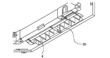
- FIG. It is a figure which shows the internal structure of the louver provided in the air conditioner main body of Embodiment 1.
- FIG. It is a figure which shows typically the structure of the air conditioner main body of Embodiment 1.
- FIG. It is a block diagram which shows the control system of the environmental control system of Embodiment 1.
- FIG. It is a figure which shows an example of the structure which realizes the function of the system control part which concerns on this disclosure. It is a figure explaining the 1st operation of the air conditioner main body of Embodiment 1.
- FIG. It is a figure explaining the 2nd operation of the air conditioner main body of Embodiment 1.
- FIG. It is a figure explaining the 1st modification of the environmental control system of Embodiment 1.
- FIG. It is a figure explaining the 2nd modification of the environmental control system of Embodiment 1.
- FIG. It is a flow diagram which shows the operation example of the environmental control system of Embodiment 1.
- FIG. It is a figure explaining the operation of the environmental control system of Embodiment 2.
- Embodiment 1 The environmental control system according to the present embodiment suppresses a decrease in the work efficiency of the user or improves the work efficiency by blowing air to the user within the target range.
- the environmental control system according to the present embodiment includes an air conditioner capable of blowing air into the target range.
- the environmental control system according to the present disclosure may be configured by a single air conditioner, or may be composed of an air conditioner and an external device that cooperates with the air conditioner.
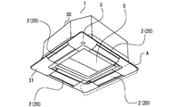
- FIG. 1 is a perspective view of an air conditioner main body 1 included in the air conditioner constituting the environmental control system of the first embodiment.
- FIG. 2 is a diagram showing an internal structure of a louver included in the air conditioner main body 1 of the first embodiment.
- FIG. 2 shows the internal structure of the portion A surrounded by the broken line in FIG.
- FIG. 3 is a diagram schematically showing the configuration of the air conditioner main body 1 of the first embodiment.
- FIG. 3A is a plan view schematically showing the configuration of the air conditioner main body 1 of the first embodiment.
- FIG. 3B is a side view schematically showing the configuration of the air conditioner main body 1 of the first embodiment.
- the air conditioner main body 1 is a device sometimes referred to as an "indoor unit".
- the air conditioner main body 1 is installed, for example, on the ceiling surface of a room in which a space of interest is formed.
- the air conditioner main body 1 corresponds to the first air conditioner main body included in the environmental control system according to the present disclosure.
- the air conditioner main body 1 can perform an air conditioning operation including a cooling operation for blowing cold air, a heating operation for blowing hot air, and a blowing operation for blowing normal temperature air. Further, the air conditioner main body 1 according to the present embodiment can execute a work efficiency improving operation of blowing wind toward the user.
- the air conditioner main body 1 includes a housing 30.
- the housing 30 of the air conditioner main body 1 is formed in a rectangular parallelepiped box shape.
- a rectangular lower surface panel 31 is provided at the lower part of the housing 30 of the air conditioner main body 1.
- a suction port 5 is formed on the lower surface panel 31.
- the suction port 5 is an opening for taking in air from the outside into the inside of the housing 30.
- the suction port 5 is arranged in the center of the lower surface panel 31.
- the air outlet 20 is formed on the lower surface panel 31.
- the air outlet 20 is an opening for blowing air from the inside of the housing 30 to the outside.
- the lower surface panel 31 is formed with four outlets 20 as an example. Each of the four outlets 20 is provided along each side of the lower panel 31.
- the environmental control system according to the present embodiment includes an air conditioner main body 1 in which a plurality of outlets 20 are formed.
- An outdoor unit is connected to the air conditioner main body 1 via a pipe through which a refrigerant flows. Illustration of this piping and outdoor unit is omitted in this disclosure.
- a heat exchanger 21 is installed in the air passage leading from the suction port 5 to the air outlet 20.
- the heat exchanger 21 heats or cools the air by exchanging heat between the air flowing through the air passage and the refrigerant. Whether the air is heated or cooled by the heat exchanger 21 depends on the type of air conditioning operation performed by the air conditioner.
- the heat exchanger 21 heats or cools the air to adjust the temperature, humidity, and the like of the air to generate conditioned air. Specifically, during the heating operation, the heat exchanger 21 heats the air. During the cooling operation, the heat exchanger 21 cools the air. Further, during the ventilation operation, the air that has passed through the heat exchanger 21 is generated as conditioned air at room temperature.
- the air conditioner main body 1 is provided with a blower 22 for blowing air from the air outlet 20.
- the blower 22 is installed in an air passage leading from the suction port 5 to the air outlet 20.
- the blower 22 generates an air flow from the suction port 5 to the air outlet 20. When the blower 22 operates, air is sucked in from the suction port 5 and air is blown out from the outlet 20.
- the air conditioner main body 1 includes, as an example, one blower 22 capable of sending an air flow to a plurality of outlets 20.
- the first air conditioner main body included in the environmental control system according to the present disclosure may include a plurality of blowers 22.
- the air conditioner main body 1 includes upper and lower louvers 2 and left and right louvers 4.
- the upper and lower louvers 2 and the left and right louvers 4 are provided in each of the plurality of outlets 20.
- the upper and lower louvers 2 are for adjusting the vertical blowout angle of the air blown out from the blowout port 20.
- the left and right louvers 4 are for adjusting the blowing angle of the air blown out from the outlet 20 in the left-right direction.
- the air conditioner main body 1 can blow air in various directions by changing the combination of the orientation of the upper and lower louvers 2 and the orientation of the left and right louvers 4.
- the upper and lower louvers 2 are configured so that the outlet 20 can be closed. In the state shown in FIG. 1, the outlet 20 is closed by the upper and lower louvers 2.
- the air conditioner main body 1 according to the present embodiment stops the blowing of air from some of the outlets 20 by blocking some of the outlets 20 with the upper and lower louvers 2. Is possible.
- the surface temperature sensor 3 is attached to the lower surface panel 31.
- the surface temperature sensor 3 can detect the surface temperature of an object within the target range in a non-contact manner.
- the surface temperature sensor 3 scans within the target range and acquires surface temperature distribution data within the target range.
- the surface temperature distribution data is also referred to as thermal image data.
- the detected surface temperature distribution data acquired by the surface temperature sensor 3 is processed by the controller unit 6 or the like, which will be described later. As a result, the position of the human body existing within the target range is detected.
- the surface temperature sensor 3 in the present embodiment constitutes an example of a human body detecting unit that detects a human body.
- the method of detecting the human body within the target range is not limited to the method of acquiring thermal image data by the surface temperature sensor 3.
- the detection of the human body may be performed by, for example, acquiring real image data with a camera and processing the real image data.
- the human body detection unit according to the present disclosure is not limited to the surface temperature sensor 3, and may be configured by the above-mentioned camera, other motion sensors installed within the target range, a wearable sensor worn by the user, or the like. Further, devices such as a surface temperature sensor 3 and a camera constituting the human body detection unit according to the present disclosure may be provided outside the air conditioner main body 1.
- FIG. 4 is a block diagram showing a control system of the environmental control system of the first embodiment.
- the environmental control system of this embodiment includes a controller unit 6 and a control board 11.
- the controller unit 6 and the control board 11 are provided in the air conditioner main body 1 as an integrated device, for example.
- the controller unit 6 and the control board 11 may be provided as external devices of the air conditioner main body 1.
- One of the controller unit 6 and the control board 11 may be provided in the air conditioner main body 1, and the other may be provided as an external device.
- the controller unit 6 and the control board 11 constitute an example of the system control unit according to the present disclosure.
- the controller unit 6 processes the surface temperature distribution data output from the surface temperature sensor 3.
- the controller unit 6 includes, for example, an information acquisition unit 7 and a person position determination unit 8.
- the information acquisition unit 7 acquires the surface temperature distribution data output from the surface temperature sensor 3.
- the human position determination unit 8 determines the position of the human body within the target range based on the surface temperature distribution data acquired by the information acquisition unit 7.
- the human position determination unit 8 determines the position of the human body from the difference in surface temperature, the distribution shape of the surface temperature, and the like.
- the environmental control system may include a temperature sensor 3a that detects the room temperature in the target range.
- the room temperature data detected by the temperature sensor 3a is acquired by the information acquisition unit 7.
- the controller unit 6 may include a room temperature determination unit 9.
- the room temperature determination unit 9 determines whether the room temperature is the set temperature of the air conditioner based on the room temperature data acquired by the information acquisition unit 7.
- the air conditioning device constituting the environmental control system according to the present embodiment may be configured to perform air conditioning operation based on the determination result of the room temperature determination unit 9.
- the control board 11 is equipped with a control circuit for controlling the overall operation of the air conditioner main body 1.
- the control board 11 includes, for example, an information processing unit 12, a control unit 13, a wind direction control unit 14, an air volume control unit 15, and an outlet opening / closing control unit 16.
- the wind direction control unit 14 controls the wind direction of the air blown out from the air outlet 20 by controlling the operation of the wind direction adjustment unit 17 provided in the air conditioner main body 1.
- the wind direction adjusting unit 17 adjusts the wind direction of the air blown out from the air outlet 20.
- the wind direction adjusting unit 17 is composed of an upper / lower louver 2, a left / right louver 4, and a device such as a motor (not shown) for moving each louver.
- the air volume control unit 15 controls the air volume and speed of the air blown out from the air outlet 20 by controlling the operation of the air volume adjusting unit 18 provided in the air conditioner main body 1.
- the air volume adjusting unit 18 adjusts the air volume and the wind speed of the air blown out from the air outlet 20.
- the air volume adjusting unit 18 is composed of a blower 22 and a device such as a motor (not shown) for driving the blower 22.
- the outlet opening / closing control unit 16 opens / closes the outlet 20 by controlling the operation of the outlet opening / closing unit 19 provided in the air conditioner main body 1.
- the outlet opening / closing unit 19 opens / closes any one of the plurality of outlets 20.
- the air outlet opening / closing unit 19 is composed of an upper / lower louver 2 and a device such as a motor (not shown) for driving the upper / lower louver 2.
- the outlet opening / closing portion 19 may be composed of, for example, a member different from the upper and lower louvers 2.
- the air conditioner main body 1 may include a member for opening and closing the air outlet 20 in addition to the upper and lower louvers 2 for adjusting the wind direction.
- the information processing unit 12 determines the control content of the air conditioner main body 1 based on the information on the position of the human body detected by the surface temperature sensor 3 and the controller unit 6.
- the control unit 13 outputs a specific control command to the wind direction control unit 14, the air volume control unit 15, and the air outlet open / close control unit 16 according to the control content determined by the information processing unit 12.
- the wind direction control unit 14, the air volume control unit 15, and the air outlet opening / closing control unit 16 control the operations of the wind direction adjusting unit 17, the air volume adjusting unit 18, and the air outlet opening / closing unit 19 according to the control command from the control unit 13.
- the information processing unit 12 has a function of determining the control content of the air conditioner main body 1 according to the distance from the human body to the air conditioner main body 1.
- the distance from the human body to the air conditioner main body 1 is defined as the distance from the human body to the reference point of the air conditioner main body 1.
- This reference point is set, for example, as the center of the air conditioner main body 1. Further, this reference point may be set as the position of the outlet 20 closest to the human body.
- the above reference point can be set at an arbitrary position according to the specifications of the human body detection unit such as the surface temperature sensor 3.
- FIG. 5 is a diagram showing an example of a configuration that realizes the function of the system control unit according to the present disclosure.
- the functions of the controller unit 6 and the control board 11 that form an example of the system control unit are realized by, for example, a processing circuit.
- the processing circuit may be dedicated hardware 40.
- the processing circuit may include a processor 41 and a memory 42.
- a part of the processing circuit may be formed as dedicated hardware 40, and the processing circuit may further include a processor 41 and a memory 42.
- a part of the processing circuit is formed as dedicated hardware 40.
- the processing circuit further includes a processor 41 and a memory 42.
- Processing circuits include, for example, single circuits, composite circuits, programmed processors, parallel programmed processors, ASICs, FPGAs, or a combination thereof. ..
- each function of the controller unit 6 and the control board 11 is realized by software, firmware, or a combination of software and firmware.
- the processor 41 realizes the functions of each part by reading and executing the program stored in the memory 42.
- the processor 41 is also referred to as a CPU (Central Processing Unit), a central processing unit, a processing unit, an arithmetic unit, a microprocessor, a microcomputer, or a DSP.
- the memory 42 corresponds to, for example, a non-volatile or volatile semiconductor memory such as RAM, ROM, flash memory, EPROM and EEPROM, or a magnetic disk, flexible disk, optical disk, compact disk, mini disk, DVD or the like.
- the processing circuit can realize each function of the controller unit 6 and the control board 11 constituting an example of the system control unit by hardware, software, firmware, or a combination thereof.
- the air conditioner main body 1 can execute the work efficiency improving operation.
- the work efficiency improving operation is an operation of blowing air toward the user, that is, the human body.
- the air conditioner main body 1 blows the air at room temperature from the air outlet 20 toward the human body by the air blowing operation.
- the air conditioner main body 1 may perform a cooling operation in which cold air is blown out when the work efficiency improving operation is executed. Further, for example, when the room temperature is below a predetermined temperature, the air conditioner main body 1 may perform a heating operation for blowing warm air at the time of executing the work efficiency improving operation.
- a specific example of the operation and control of the air conditioner main body 1 that blows air at the time of executing the work efficiency improvement operation and the environmental control system including the air conditioner main body 1 will be described.
- the controller unit 6 and the control board 11 which are examples of the system control unit are the first when the distance from the human body detected by the surface temperature sensor 3 to the air conditioner main body 1 is the first distance. 1 Execute control. Further, the controller unit 6 and the control board 11 perform the second control when the distance from the human body detected by the surface temperature sensor 3 to the air conditioner main body 1 is a second distance larger than the above first distance. Run.
- the above first distance is less than the preset first threshold value D1. Further, the above-mentioned second distance is equal to or higher than the first threshold value D1. That is, the controller unit 6 and the control board 11 execute the first control when the distance from the human body detected by the surface temperature sensor 3 to the air conditioner main body 1 is less than the first threshold value D1. The controller unit 6 and the control board 11 execute the second control when the distance from the human body detected by the surface temperature sensor 3 to the air conditioner main body 1 is equal to or greater than the first threshold value D1.
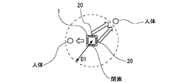
- FIG. 6 is a diagram illustrating the first operation of the air conditioner main body 1 of the first embodiment. Further, when the above-mentioned second control is executed, the air conditioner main body 1 executes the second operation.
- FIG. 7 is a diagram illustrating a second operation of the air conditioner main body 1 of the first embodiment. In FIGS. 6 and 7, the arrows indicate the flow of air blown out by the air conditioner main body 1.
- the first operation is an operation of blowing air from one outlet 20 toward the human body.
- air is blown toward each worker.
- the air conditioner main body 1 may blow air toward the human body from the outlet 20 closest to the human body.
- the second operation is an operation of blowing air toward the human body from at least two, that is, a plurality of outlets 20.
- the air conditioner main body 1 provided in the control system according to the present embodiment has air from a plurality of outlets 20 toward a distant human body separated from the air conditioner main body 1 by the first threshold value D1 or more.
- the second operation of blowing out is performed. According to the second operation described above, it is possible to blow a sufficiently strong wind to an operator far away from the air conditioner main body 1.
- the air conditioner main body 1 may perform the first operation and the second operation in parallel.
- the air conditioner main body 1 blows air from a plurality of outlets 20 toward a human body whose distance from the air conditioner main body 1 is a first threshold value D1 or more by a second distance, and the air conditioner main body 1 is the air conditioner. Air may be blown out from one outlet 20 toward the human body whose distance from the main body 1 is less than the first threshold value D1. That is, the first control and the second control may be executed in parallel.
- the air conditioner main body 1 may close at least one outlet 20 when the second control is executed and the second operation is executed.
- closing at least one outlet 20 it is possible to increase the wind speed of the air blown out by the air conditioner main body 1 without increasing the output of the blower 22.
- the air outlet 20 to be closed may be in a direction other than the direction in which the operator is with respect to the air conditioner main body 1.
- the air outlet 20 to be closed may be selected according to the position of the human body detected by the surface temperature sensor 3.
- FIG. 8 is a diagram illustrating a first modification of the environmental control system of the first embodiment.
- the environmental control system of the present embodiment may further include an air conditioner main body 1a different from the air conditioner main body 1.
- the air conditioner main body 1a corresponds to the second air conditioner main body included in the environmental control system according to the present disclosure.
- the second air conditioner main body according to the present disclosure may have different specifications from the air conditioner main body 1a.
- the second air conditioner main body may be provided with, for example, one outlet.
- the air conditioner main body 1a is configured in the same manner as the air conditioner main body 1. As shown in FIG. 4, for example, the operation of the air conditioner main body 1a is controlled by the controller unit 6 and the control board 11 which are examples of the system control unit.
- the controller unit 6 and the control board 11 have a third distance in which the distance from the human body detected by the surface temperature sensor 3 to the air conditioner main body 1 is larger than the second distance.
- the third control is executed.
- This third distance is equal to or greater than the preset second threshold value D2.
- the second distance is less than the second threshold D2.
- the second threshold value D2 is set as a value larger than the first threshold value D1.
- both the air conditioner main body 1 and the air conditioner main body 1a are distant from the air conditioner main body 1 by a second threshold value D2 or more. Blow air toward the human body.
- this first modification by sending air from another air conditioner main body 1a to a worker far away from the air conditioner main body 1, a wind having sufficient strength is sent to the worker. You can guess.
- the air conditioner main body 1a is configured in the same manner as the air conditioner main body 1 as an example.
- the air conditioner main body 1a may execute the first operation of blowing air from one outlet 20 and the second operation of blowing air from a plurality of outlets 20, similarly to the air conditioner main body 1. good.
- the controller unit 6 and the control board 11 execute the first control when the distance from the human body to the air conditioner main body 1a is the fourth distance, and the distance from the human body to the air conditioner main body 1a is the above. If the fifth distance is larger than the fourth distance, the second control may be executed.
- the fourth distance is less than the preset third threshold D3.
- the fifth distance is equal to or greater than the third threshold value D3.
- the air conditioner main body 1a may execute the first operation when the distance from the human body to the air conditioner main body 1a is less than the third threshold value D3.
- the air conditioner main body 1a may execute the second operation when the distance from the human body to the air conditioner main body 1a is equal to or greater than the third threshold value D3.
- the third threshold value D3 may be the same as or different from the first threshold value D1.
- the third control may be executed when the distance from the human body to the air conditioner main body 1a is the sixth distance.
- This sixth distance is equal to or greater than the fourth threshold value D4.
- the fifth distance is less than the fourth threshold D4. That is, as shown in FIG. 8, in the controller unit 6 and the control board 11, the distance from the human body to the air conditioner main body 1 is the second threshold value D2 or more, and the distance from the human body to the air conditioner main body 1a is the first. 4
- the third control may be executed when the threshold value is D4 or more.
- the fourth threshold value D4 may be the same as or different from the above-mentioned second threshold value D2.
- the air conditioner main body 1 may close at least one outlet 20 when the third control is executed.
- the air outlet 20 to be closed may be in a direction other than the direction in which the operator is with respect to the air conditioner main body 1.
- the air conditioner main body 1a configured in the same manner as the air conditioner main body 1 may also close at least one outlet 20 when the third control is executed.
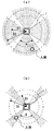
- FIG. 9 is a diagram illustrating a second modification of the environmental control system of the first embodiment.
- the value of the first threshold value D1 is changed according to the position of the human body with respect to the air conditioner main body 1.
- the first threshold value D1 is set from the human body to the human body when the apparent area of the outlet 20 when the outlet 20 closest to the human body is seen from the human body is the first area.
- the apparent area of the outlet 20 when the nearest outlet 20 is viewed is set to be smaller than the case where the second area is larger than the first area.
- FIG. 9A shows a state in which the apparent area of the outlet 20 when the outlet 20 closest to the human body is viewed from the human body is a second area larger than the first area.
- This state means a state in which the human body exists within a predetermined angle range A with respect to the front direction of the air outlet 20.
- This angle range A is set with reference to, for example, the center of the air outlet 20 or the center of the air conditioner main body 1.
- FIG. 9B shows a state in which the apparent area of the outlet 20 when the outlet 20 closest to the human body is viewed from the human body is the first area smaller than the second area. ..
- This state means a state in which the human body exists outside the above-mentioned angle range A with respect to the front direction of the air outlet 20.
- the first threshold value D1 in the state of FIG. 9B is set smaller than the first threshold value D1 in the state of FIG. 9A.
- the first threshold value is set.
- the first threshold value D1 may change discontinuously depending on whether or not it is in the predetermined angle range A as described above, or continuously according to the position of the human body with respect to the front direction of the outlet 20. It may change.
- the first threshold value D1 may be continuously changed according to the size of the apparent area of the outlet 20 when the outlet 20 closest to the human body is viewed from the human body.
- the second threshold value D2 is also the human body when the apparent area of the outlet 20 when the outlet 20 closest to the human body is viewed from the human body is the first area.
- the apparent area of the outlet 20 when the outlet 20 closest to the human body is viewed from the above may be set smaller than the case where the second area is larger than the first area.
- the second threshold value D2 in the state of FIG. 9B is set smaller than the second threshold value D2 in the state of FIG. 9A.
- FIG. 10 is a flow chart showing an operation example of the environmental control system of the first embodiment.
- the environmental control system first acquires room temperature by the temperature sensor 3a, the information acquisition unit 7, and the like (step S101).
- the environmental control system acquires the position information of the worker by the surface temperature sensor 3, the information acquisition unit 7, and the like (step S102).
- step S103 based on the room temperature information acquired in step S101, it is determined whether the room temperature has reached the target temperature (step S103).
- the target temperature is set according to the set temperature of the air conditioner constituting the environmental control system. If the room temperature has not reached the target temperature, a cooling operation or a heating operation is executed by the air conditioner main body 1 depending on the room temperature (step S104). The process from step S101 to step S104 is continued until the room temperature reaches the target temperature.
- the work efficiency improving operation is executed by the air conditioner main body 1.
- the first threshold value D1 and the second threshold value D2 which are the threshold values of the distance, may be set according to the position information of the worker acquired in step S102 (step S105).
- the first threshold value D1 and the second threshold value D2 are set as in the example of FIG. 9, for example.
- the control content of the operation of the air conditioner main body 1 is determined based on the position information of the worker and the first threshold value D1 and the second threshold value D2 (step 106). ..
- the controller unit 6 and the control board 11 which are examples of the system control unit have the above-mentioned first control, second control, third control, etc. based on the position information of the operator and the first threshold value D1 and the second threshold value D2. Is executed as appropriate.
- the air conditioner main body 1 performs the ventilation operation according to the control contents of the controller unit 6 and the control board 11 (step S107). This delivers airflow to the operator.
- the flow diagram of FIG. 10 shows only an example of operation, and the operation flow of the environmental control system according to the present disclosure is not limited to this example.
- Embodiment 2 Next, the second embodiment will be described. The description of the same or corresponding parts as those of the first embodiment will be simplified and omitted. Hereinafter, the differences from the first embodiment will be mainly described.
- FIG. 11 is a diagram illustrating the operation of the environmental control system according to the second embodiment. Similar to the first embodiment, the environmental control system according to the present embodiment includes an air conditioner main body 1 which is an example of the first air conditioner main body.
- the air conditioner main body 1 executes a work efficiency improving operation of blowing air from the air outlet 20 toward the human body.
- the controller unit 6 and the control board 11 which are examples of the system control unit are the first when the distance from the human body detected by the surface temperature sensor 3 to the air conditioner main body 1 is the first distance. 1 Execute control. Further, the controller unit 6 and the control board 11 perform the second control when the distance from the human body detected by the surface temperature sensor 3 to the air conditioner main body 1 is a second distance larger than the above first distance. Run. The first distance is less than the first threshold D1 and the second distance is greater than or equal to the first threshold D1.
- the first threshold value D1 is a threshold value of the same distance as in the first embodiment.
- the first control in the present embodiment is different from the first control in the first embodiment.
- the second control in the present embodiment is different from the second control in the first embodiment.
- the air conditioner main body 1 blows air at the first wind speed toward the human body detected by the surface temperature sensor 3 which is an example of the human body detecting unit.
- the air conditioner main body 1 blows air toward the human body detected by the surface temperature sensor 3 at a second wind speed higher than the first wind speed. That is, the air conditioner main body 1 of the present embodiment blows air from the air conditioner main body 1 toward a human body far away from the first threshold value D1 or more at a larger second wind speed. This makes it possible to more reliably achieve the effect of improving the work efficiency of the operator far away from the air conditioner main body 1.
- the air conditioner main body 1 closes at least one outlet 20 when the second control is executed. As a result, the air conditioner main body 1 can blow out a stronger wind. It is preferable that the air conditioner 20 to be closed is closed in a direction other than the direction in which the operator is with respect to the air conditioner main body 1.
- Embodiment 3 Next, the third embodiment will be described. The description of the same or corresponding parts as those of the above embodiments will be simplified and omitted. Hereinafter, the differences from each of the above embodiments will be mainly described.
- FIG. 12 is a diagram illustrating the operation of the environmental control system according to the third embodiment.
- the environmental control system according to the present embodiment includes an air conditioner main body 1 and an air conditioner main body 1a, as in the first modification shown in FIG. 8 in the first embodiment.
- the air conditioner main body 1 and the air conditioner main body 1a perform a work efficiency improving operation of blowing air toward the human body.
- the air conditioner main body 1 which is an example of the first air conditioner main body may be provided with one outlet.
- the air conditioner main body 1a which is an example of the second air conditioner main body, may also have one outlet.
- the controller unit 6 and the control board 11 which are examples of the system control unit are the first when the distance from the human body detected by the surface temperature sensor 3 to the air conditioner main body 1 is the first distance. 1 Execute control. Further, the controller unit 6 and the control board 11 perform the second control when the distance from the human body detected by the surface temperature sensor 3 to the air conditioner main body 1 is a second distance larger than the above first distance. Run. The first distance is less than the first threshold D1 and the second distance is greater than or equal to the first threshold D1.
- the first threshold value D1 is a threshold value of the same distance as in the first embodiment.
- the first control in the present embodiment is different from the first control in the first embodiment and the second embodiment.
- the second control in the present embodiment is different from the second control in the first and second embodiments.
- the air conditioner main body 1 blows air toward the human body detected by the surface temperature sensor 3 which is an example of the human body detecting unit. That is, air is blown from the air conditioner main body 1 to the human body whose distance to the air conditioner main body 1 is less than the first threshold value D1.
- both the air conditioner main body 1 and the air conditioner main body 1a blow out air toward the human body detected by the surface temperature sensor 3.
- a worker far away from the air conditioner main body 1 is blown with a sufficient amount of wind by sending air from another air conditioner main body 1a. be able to.
- the outlet 20 other than the direction in which the operator is present with respect to the air conditioner main body 1 may be closed as shown in FIG.
- the air conditioner main body 1a is configured in the same manner as the air conditioner main body 1 as an example.
- the third threshold value D3 may be set in the air conditioner main body 1a as in the first modification shown in FIG. 8 in the first embodiment.
- the distance from the human body to the air conditioner main body 1 is the first threshold value D1 or more
- the distance from the human body to the air conditioner main body 1a is the third threshold value D3 or more.
- the above-mentioned second control may be executed. According to this example, a wind of sufficient strength can be applied to a worker who is located far away from both the air conditioner main body 1 and the air conditioner main body 1a.
- Embodiment 4 Next, the fourth embodiment will be described. The description of the same or corresponding parts as those of the above embodiments will be simplified and omitted. Hereinafter, the differences from each of the above embodiments will be mainly described.
- FIG. 13 is a diagram illustrating the operation of the environmental control system according to the fourth embodiment.
- the environmental control system according to the present embodiment includes an air conditioner main body 1 and an air conditioner main body 1a, as in the third embodiment.
- the air conditioner main body 1 and the air conditioner main body 1a perform a work efficiency improving operation of blowing air toward the human body.
- the air conditioner main body 1 which is an example of the first air conditioner main body may be provided with one outlet.
- the air conditioner main body 1a which is an example of the second air conditioner main body, may also have one outlet.
- the air conditioner main body 1 is configured to be able to blow air to the first area.
- the air conditioner main body 1 is installed so as to blow air to a worker in the first area.
- the air conditioner main body 1a is configured to be able to blow air to a second area different from the first area.
- the air conditioner main body 1a is installed so as to blow air to workers in the second area.
- the surface temperature sensor 3 which is an example of the human body detection unit can detect the human body existing in the first area and the second area.
- the controller unit 6 is configured to be able to determine the number of human bodies in the first area and the number of human bodies in the second area detected by the surface temperature sensor 3. This determination function is provided in, for example, a human position determination unit.
- the controller unit 6 and the control board 11, which are examples of the system control unit, have the air conditioner main body 1 and the air conditioner main body 1a according to the number of human bodies in the first area and the number of human bodies in the second area. Control.
- the controller unit 6 and the control board 11 have an air conditioner main body when the number of human bodies in the first area is equal to or more than the reference value and the number of human bodies in the second area is less than the reference value. Both 1 and the air conditioner main body 1a are made to blow air toward the human body in the first area.
- the above two reference values may be the same or different. According to this embodiment, it is possible to deliver a strong air flow to a space with many workers.
- the environmental control system according to the present disclosure can be used, for example, to improve the work efficiency of a worker in a work space such as an office in which an air conditioner is installed.
- Air conditioner body 1 Air conditioner body, 1a Air conditioner body, 2 Upper and lower louvers, 3 Surface temperature sensor, 3a temperature sensor, 4 Left and right louvers, 5 Suction port, 6 Controller unit, 7 Information acquisition unit, 8 Person position determination unit, 9 Room temperature Judgment unit, 11 control board, 12 information processing unit, 13 control unit, 14 wind direction control unit, 15 air volume control unit, 16 air outlet opening / closing control unit, 17 wind direction adjustment unit, 18 air volume adjustment unit, 19 air outlet opening / closing unit, 20 Outlet, 21 heat exchanger, 22 blower, 30 housing, 31 bottom panel, 40 dedicated hardware, 41 processor, 42 memory
Landscapes
- Engineering & Computer Science (AREA)
- Chemical & Material Sciences (AREA)
- Combustion & Propulsion (AREA)
- Mechanical Engineering (AREA)
- General Engineering & Computer Science (AREA)
- Physics & Mathematics (AREA)
- Fluid Mechanics (AREA)
- Signal Processing (AREA)
- Fuzzy Systems (AREA)
- Mathematical Physics (AREA)
- Air Conditioning Control Device (AREA)
Priority Applications (5)
| Application Number | Priority Date | Filing Date | Title |
|---|---|---|---|
| CN202080100921.9A CN115667811A (zh) | 2020-06-02 | 2020-06-02 | 环境控制系统 |
| JP2022529189A JPWO2021245804A1 (https=) | 2020-06-02 | 2020-06-02 | |
| US17/913,263 US20230151995A1 (en) | 2020-06-02 | 2020-06-02 | Environmental control system |
| EP20938754.7A EP4160104A4 (en) | 2020-06-02 | 2020-06-02 | ENVIRONMENTAL CONTROL SYSTEM |
| PCT/JP2020/021818 WO2021245804A1 (ja) | 2020-06-02 | 2020-06-02 | 環境制御システム |
Applications Claiming Priority (1)
| Application Number | Priority Date | Filing Date | Title |
|---|---|---|---|
| PCT/JP2020/021818 WO2021245804A1 (ja) | 2020-06-02 | 2020-06-02 | 環境制御システム |
Publications (1)
| Publication Number | Publication Date |
|---|---|
| WO2021245804A1 true WO2021245804A1 (ja) | 2021-12-09 |
Family
ID=78831045
Family Applications (1)
| Application Number | Title | Priority Date | Filing Date |
|---|---|---|---|
| PCT/JP2020/021818 Ceased WO2021245804A1 (ja) | 2020-06-02 | 2020-06-02 | 環境制御システム |
Country Status (5)
| Country | Link |
|---|---|
| US (1) | US20230151995A1 (https=) |
| EP (1) | EP4160104A4 (https=) |
| JP (1) | JPWO2021245804A1 (https=) |
| CN (1) | CN115667811A (https=) |
| WO (1) | WO2021245804A1 (https=) |
Families Citing this family (1)
| Publication number | Priority date | Publication date | Assignee | Title |
|---|---|---|---|---|
| GB2631317A (en) * | 2023-06-28 | 2025-01-01 | Dyson Technology Ltd | Directing an airflow towards a human |
Citations (4)
| Publication number | Priority date | Publication date | Assignee | Title |
|---|---|---|---|---|
| JP2010255900A (ja) * | 2009-04-23 | 2010-11-11 | Mitsubishi Electric Corp | 空気調和システム |
| JP2011190941A (ja) * | 2010-03-12 | 2011-09-29 | Hitachi Appliances Inc | 空気調和機 |
| JP2013238376A (ja) * | 2012-05-16 | 2013-11-28 | Mitsubishi Electric Corp | 空気調和装置 |
| JP2016200311A (ja) * | 2015-04-08 | 2016-12-01 | ジョンソンコントロールズ ヒタチ エア コンディショニング テクノロジー(ホンコン)リミテッド | 空気調和システム |
Family Cites Families (14)
| Publication number | Priority date | Publication date | Assignee | Title |
|---|---|---|---|---|
| JPH05223299A (ja) * | 1991-10-30 | 1993-08-31 | Norm Pacific Autom Corp | 人体の動きで自動的に調整及び制御される換気装置 |
| ID16934A (id) * | 1996-05-22 | 1997-11-20 | Samsung Electronics Co Ltd | Alat kontrol arah dan kecepatan alir udara yang dikeluarkan oleh mesin penyejuk udara dan metoda kerjanya |
| JP2008196842A (ja) * | 2007-01-17 | 2008-08-28 | Daikin Ind Ltd | 空調制御システム |
| JP2010139210A (ja) * | 2008-12-15 | 2010-06-24 | Panasonic Corp | 空気調和機 |
| JP2011137565A (ja) * | 2009-12-25 | 2011-07-14 | Mitsubishi Heavy Ind Ltd | 空気調和機 |
| JP2011174693A (ja) * | 2010-01-26 | 2011-09-08 | Daikin Industries Ltd | 空気調和装置の天井設置型室内ユニット |
| CN109564021A (zh) * | 2016-08-09 | 2019-04-02 | 三菱电机株式会社 | 空调装置 |
| US11512866B2 (en) * | 2017-06-15 | 2022-11-29 | Mitsubishi Electric Corporation | Indoor unit for air-conditioning apparatus |
| DE112017007798B4 (de) * | 2017-07-31 | 2026-02-26 | Mitsubishi Electric Corporation | Klimatisierungssystem und zonale-klimatisierung-steuerungsverfahren |
| JP7206684B2 (ja) * | 2018-08-08 | 2023-01-18 | 三菱電機株式会社 | 環境制御システムおよび空気調和装置 |
| CN110873444A (zh) * | 2018-08-31 | 2020-03-10 | 青岛海尔智能技术研发有限公司 | 空调器控制方法及装置、空调器、计算机设备、存储介质 |
| CN109631272A (zh) * | 2018-12-29 | 2019-04-16 | 青岛海尔空调器有限总公司 | 空调的控制方法、装置、存储介质及计算机设备 |
| CN110410999B (zh) * | 2019-07-19 | 2021-04-27 | 上海交通大学 | 一种顶板分布式多风口协同个性化送风方法及送风系统 |
| CN110986314A (zh) * | 2019-12-05 | 2020-04-10 | 青岛海尔空调器有限总公司 | 空调器的智能送风调节方法及空调器 |
-
2020
- 2020-06-02 JP JP2022529189A patent/JPWO2021245804A1/ja not_active Ceased
- 2020-06-02 WO PCT/JP2020/021818 patent/WO2021245804A1/ja not_active Ceased
- 2020-06-02 CN CN202080100921.9A patent/CN115667811A/zh active Pending
- 2020-06-02 EP EP20938754.7A patent/EP4160104A4/en not_active Withdrawn
- 2020-06-02 US US17/913,263 patent/US20230151995A1/en not_active Abandoned
Patent Citations (4)
| Publication number | Priority date | Publication date | Assignee | Title |
|---|---|---|---|---|
| JP2010255900A (ja) * | 2009-04-23 | 2010-11-11 | Mitsubishi Electric Corp | 空気調和システム |
| JP2011190941A (ja) * | 2010-03-12 | 2011-09-29 | Hitachi Appliances Inc | 空気調和機 |
| JP2013238376A (ja) * | 2012-05-16 | 2013-11-28 | Mitsubishi Electric Corp | 空気調和装置 |
| JP2016200311A (ja) * | 2015-04-08 | 2016-12-01 | ジョンソンコントロールズ ヒタチ エア コンディショニング テクノロジー(ホンコン)リミテッド | 空気調和システム |
Non-Patent Citations (1)
| Title |
|---|
| See also references of EP4160104A4 * |
Also Published As
| Publication number | Publication date |
|---|---|
| US20230151995A1 (en) | 2023-05-18 |
| EP4160104A4 (en) | 2023-07-19 |
| CN115667811A (zh) | 2023-01-31 |
| EP4160104A1 (en) | 2023-04-05 |
| JPWO2021245804A1 (https=) | 2021-12-09 |
Similar Documents
| Publication | Publication Date | Title |
|---|---|---|
| EP3499141B1 (en) | Air conditioner | |
| EP3104092A1 (en) | Indoor unit for air conditioner | |
| CN104006446B (zh) | 室内机和空气调节装置 | |
| CN107726444B (zh) | 空气调节机 | |
| JP6678728B2 (ja) | 空調システム | |
| JP2014020670A5 (https=) | ||
| CN108474581B (zh) | 空调系统 | |
| JP6808999B2 (ja) | 空気調和機 | |
| JP7206684B2 (ja) | 環境制御システムおよび空気調和装置 | |
| JP7163662B2 (ja) | 環境制御システムおよび空気調和装置 | |
| JP5316473B2 (ja) | 空気調和装置 | |
| JP6599022B2 (ja) | 空気調和機の室内機 | |
| US20190041083A1 (en) | Air-conditioning system | |
| CN211041167U (zh) | 空调装置的室内机 | |
| WO2021245804A1 (ja) | 環境制御システム | |
| JP7161329B2 (ja) | 制御装置、空調システム及び制御方法 | |
| JP7230339B2 (ja) | 空気調和装置 | |
| JP2021096050A (ja) | 環境制御システム | |
| JP7439426B2 (ja) | 環境制御システム | |
| CN107726492B (zh) | 空气调节机 | |
| JP6559340B2 (ja) | 空気調和機 | |
| JPWO2022153386A5 (https=) | ||
| JP2022066788A (ja) | 換気装置及び換気送風システム | |
| KR20180027658A (ko) | 이동형 공조장치 | |
| JPH05118618A (ja) | 空気調和装置の運転制御装置 |
Legal Events
| Date | Code | Title | Description |
|---|---|---|---|
| 121 | Ep: the epo has been informed by wipo that ep was designated in this application |
Ref document number: 20938754 Country of ref document: EP Kind code of ref document: A1 |
|
| ENP | Entry into the national phase |
Ref document number: 2022529189 Country of ref document: JP Kind code of ref document: A |
|
| NENP | Non-entry into the national phase |
Ref country code: DE |
|
| ENP | Entry into the national phase |
Ref document number: 2020938754 Country of ref document: EP Effective date: 20230102 |