WO2021245734A1 - 熱交換器及び冷凍サイクル装置 - Google Patents
熱交換器及び冷凍サイクル装置 Download PDFInfo
- Publication number
- WO2021245734A1 WO2021245734A1 PCT/JP2020/021578 JP2020021578W WO2021245734A1 WO 2021245734 A1 WO2021245734 A1 WO 2021245734A1 JP 2020021578 W JP2020021578 W JP 2020021578W WO 2021245734 A1 WO2021245734 A1 WO 2021245734A1
- Authority
- WO
- WIPO (PCT)
- Prior art keywords
- heat transfer
- heat exchanger
- header
- spacer portion
- spacer
- Prior art date
- Legal status (The legal status is an assumption and is not a legal conclusion. Google has not performed a legal analysis and makes no representation as to the accuracy of the status listed.)
- Ceased
Links
Images


Classifications
-
- F—MECHANICAL ENGINEERING; LIGHTING; HEATING; WEAPONS; BLASTING
- F28—HEAT EXCHANGE IN GENERAL
- F28D—HEAT-EXCHANGE APPARATUS, NOT PROVIDED FOR IN ANOTHER SUBCLASS, IN WHICH THE HEAT-EXCHANGE MEDIA DO NOT COME INTO DIRECT CONTACT
- F28D1/00—Heat-exchange apparatus having stationary conduit assemblies for one heat-exchange medium only, the media being in contact with different sides of the conduit wall, in which the other heat-exchange medium is a large body of fluid, e.g. domestic or motor car radiators
- F28D1/02—Heat-exchange apparatus having stationary conduit assemblies for one heat-exchange medium only, the media being in contact with different sides of the conduit wall, in which the other heat-exchange medium is a large body of fluid, e.g. domestic or motor car radiators with heat-exchange conduits immersed in the body of fluid
- F28D1/04—Heat-exchange apparatus having stationary conduit assemblies for one heat-exchange medium only, the media being in contact with different sides of the conduit wall, in which the other heat-exchange medium is a large body of fluid, e.g. domestic or motor car radiators with heat-exchange conduits immersed in the body of fluid with tubular conduits
- F28D1/053—Heat-exchange apparatus having stationary conduit assemblies for one heat-exchange medium only, the media being in contact with different sides of the conduit wall, in which the other heat-exchange medium is a large body of fluid, e.g. domestic or motor car radiators with heat-exchange conduits immersed in the body of fluid with tubular conduits the conduits being straight
- F28D1/0535—Heat-exchange apparatus having stationary conduit assemblies for one heat-exchange medium only, the media being in contact with different sides of the conduit wall, in which the other heat-exchange medium is a large body of fluid, e.g. domestic or motor car radiators with heat-exchange conduits immersed in the body of fluid with tubular conduits the conduits being straight the conduits having a non-circular cross-section
- F28D1/05366—Assemblies of conduits connected to common headers, e.g. core type radiators
- F28D1/05383—Assemblies of conduits connected to common headers, e.g. core type radiators with multiple rows of conduits or with multi-channel conduits
-
- F—MECHANICAL ENGINEERING; LIGHTING; HEATING; WEAPONS; BLASTING
- F25—REFRIGERATION OR COOLING; COMBINED HEATING AND REFRIGERATION SYSTEMS; HEAT PUMP SYSTEMS; MANUFACTURE OR STORAGE OF ICE; LIQUEFACTION SOLIDIFICATION OF GASES
- F25B—REFRIGERATION MACHINES, PLANTS OR SYSTEMS; COMBINED HEATING AND REFRIGERATION SYSTEMS; HEAT PUMP SYSTEMS
- F25B39/00—Evaporators; Condensers
-
- F—MECHANICAL ENGINEERING; LIGHTING; HEATING; WEAPONS; BLASTING
- F28—HEAT EXCHANGE IN GENERAL
- F28D—HEAT-EXCHANGE APPARATUS, NOT PROVIDED FOR IN ANOTHER SUBCLASS, IN WHICH THE HEAT-EXCHANGE MEDIA DO NOT COME INTO DIRECT CONTACT
- F28D1/00—Heat-exchange apparatus having stationary conduit assemblies for one heat-exchange medium only, the media being in contact with different sides of the conduit wall, in which the other heat-exchange medium is a large body of fluid, e.g. domestic or motor car radiators
- F28D1/02—Heat-exchange apparatus having stationary conduit assemblies for one heat-exchange medium only, the media being in contact with different sides of the conduit wall, in which the other heat-exchange medium is a large body of fluid, e.g. domestic or motor car radiators with heat-exchange conduits immersed in the body of fluid
- F28D1/04—Heat-exchange apparatus having stationary conduit assemblies for one heat-exchange medium only, the media being in contact with different sides of the conduit wall, in which the other heat-exchange medium is a large body of fluid, e.g. domestic or motor car radiators with heat-exchange conduits immersed in the body of fluid with tubular conduits
- F28D1/053—Heat-exchange apparatus having stationary conduit assemblies for one heat-exchange medium only, the media being in contact with different sides of the conduit wall, in which the other heat-exchange medium is a large body of fluid, e.g. domestic or motor car radiators with heat-exchange conduits immersed in the body of fluid with tubular conduits the conduits being straight
-
- F—MECHANICAL ENGINEERING; LIGHTING; HEATING; WEAPONS; BLASTING
- F28—HEAT EXCHANGE IN GENERAL
- F28F—DETAILS OF HEAT-EXCHANGE AND HEAT-TRANSFER APPARATUS, OF GENERAL APPLICATION
- F28F1/00—Tubular elements; Assemblies of tubular elements
- F28F1/02—Tubular elements of cross-section which is non-circular
-
- F—MECHANICAL ENGINEERING; LIGHTING; HEATING; WEAPONS; BLASTING
- F28—HEAT EXCHANGE IN GENERAL
- F28F—DETAILS OF HEAT-EXCHANGE AND HEAT-TRANSFER APPARATUS, OF GENERAL APPLICATION
- F28F1/00—Tubular elements; Assemblies of tubular elements
- F28F1/10—Tubular elements and assemblies thereof with means for increasing heat-transfer area, e.g. with fins, with projections, with recesses
- F28F1/12—Tubular elements and assemblies thereof with means for increasing heat-transfer area, e.g. with fins, with projections, with recesses the means being only outside the tubular element
- F28F1/14—Tubular elements and assemblies thereof with means for increasing heat-transfer area, e.g. with fins, with projections, with recesses the means being only outside the tubular element and extending longitudinally
- F28F1/16—Tubular elements and assemblies thereof with means for increasing heat-transfer area, e.g. with fins, with projections, with recesses the means being only outside the tubular element and extending longitudinally the means being integral with the element, e.g. formed by extrusion
-
- F—MECHANICAL ENGINEERING; LIGHTING; HEATING; WEAPONS; BLASTING
- F28—HEAT EXCHANGE IN GENERAL
- F28F—DETAILS OF HEAT-EXCHANGE AND HEAT-TRANSFER APPARATUS, OF GENERAL APPLICATION
- F28F1/00—Tubular elements; Assemblies of tubular elements
- F28F1/10—Tubular elements and assemblies thereof with means for increasing heat-transfer area, e.g. with fins, with projections, with recesses
- F28F1/12—Tubular elements and assemblies thereof with means for increasing heat-transfer area, e.g. with fins, with projections, with recesses the means being only outside the tubular element
- F28F1/14—Tubular elements and assemblies thereof with means for increasing heat-transfer area, e.g. with fins, with projections, with recesses the means being only outside the tubular element and extending longitudinally
- F28F1/20—Tubular elements and assemblies thereof with means for increasing heat-transfer area, e.g. with fins, with projections, with recesses the means being only outside the tubular element and extending longitudinally the means being attachable to the element
-
- F—MECHANICAL ENGINEERING; LIGHTING; HEATING; WEAPONS; BLASTING
- F28—HEAT EXCHANGE IN GENERAL
- F28F—DETAILS OF HEAT-EXCHANGE AND HEAT-TRANSFER APPARATUS, OF GENERAL APPLICATION
- F28F1/00—Tubular elements; Assemblies of tubular elements
- F28F1/10—Tubular elements and assemblies thereof with means for increasing heat-transfer area, e.g. with fins, with projections, with recesses
- F28F1/12—Tubular elements and assemblies thereof with means for increasing heat-transfer area, e.g. with fins, with projections, with recesses the means being only outside the tubular element
- F28F1/14—Tubular elements and assemblies thereof with means for increasing heat-transfer area, e.g. with fins, with projections, with recesses the means being only outside the tubular element and extending longitudinally
- F28F1/22—Tubular elements and assemblies thereof with means for increasing heat-transfer area, e.g. with fins, with projections, with recesses the means being only outside the tubular element and extending longitudinally the means having portions engaging further tubular elements
Definitions
- the present disclosure relates to a heat exchanger and a refrigeration cycle device that exchange heat between a refrigerant and air.
- a finless heat exchanger in which fins are not provided in the alignment direction of heat transfer tubes is known. Since the finless heat exchanger has no fins, there is no binding force for holding the heat transfer tube in the alignment direction of the heat transfer tube. Therefore, the heat transfer tube tends to bend due to thermal stress and assembly error. As a result, it is difficult to make the pitches of adjacent heat transfer tubes uniform. If there is a locally narrow pitch portion in the adjacent heat transfer tubes, the ventilation resistance increases due to the drift of air, and clogging due to dust and clogging due to frost at the time of frost formation are likely to occur.
- Patent Document 1 provides a heat exchanger in which a comb-shaped auxiliary member extending along the arrangement direction of the refrigerant flow path is provided between adjacent heat transfer tubes. Is disclosed. As a result, Patent Document 1 attempts to maintain a uniform pitch between adjacent heat transfer tubes.
- the present disclosure has been made to solve the above-mentioned problems, and provides a heat exchanger and a refrigerating cycle device that enhance the heat transfer property of the heat transfer tubes while making the pitches of the heat transfer tubes uniform.
- the heat exchanger according to the present disclosure is provided with a first header that collects and delivers the refrigerant and extends in the first direction, and a second header that is provided at a position facing the first header and extends in the first direction for collecting and delivering the refrigerant. And a plurality of heat transfer members extending from the first header toward the second header and provided at intervals along the first direction, the heat transfer member is the first from the first header. It has a plurality of heat transfer tubes extending toward the header of No. 2 and flowing a refrigerant inside, and an extending portion provided in the heat transfer tube to promote the heat transfer property of the heat transfer tube, and the extending portion is provided from the heat transfer tube. It has a base portion extending in a second direction, which is the flow direction of air flowing between the plurality of heat transfer tubes, and a spacer portion extending from the base portion in the first direction and abutting on adjacent heat transfer members.
- a heat transfer member having a heat transfer tube and an extending portion is provided, and the extending portion has a spacer portion extending in the first direction from the base portion and abutting on adjacent heat transfer members. Since the spacer portion is in contact with the adjacent heat transfer member, the pitch between the heat transfer tubes can be made uniform. Further, since the extending portion has a base portion extending in the second direction from the heat transfer tube, the heat transfer property of the heat transfer tube is enhanced. In this way, the heat exchanger can improve the heat transferability of the heat transfer tubes while making the pitches of the heat transfer tubes uniform.
- FIG. It is a circuit diagram which shows the refrigeration cycle apparatus which concerns on Embodiment 1.
- FIG. It is a perspective view which shows the heat exchanger which concerns on Embodiment 1.
- FIG. It is a front view which shows the heat exchanger which concerns on Embodiment 1.
- FIG. It is a top view which shows the state which the 1st header of the heat exchanger which concerns on Embodiment 1 is removed.
- It is a side view which shows the manufacturing method of the heat exchanger which concerns on Embodiment 1.
- FIG. It is a top view which shows the state which the 1st header of the heat exchanger which concerns on 1st modification of Embodiment 1 is removed.
- FIG. 1 is a circuit diagram showing a refrigeration cycle device 1 according to the first embodiment.
- the refrigeration cycle device 1 is, for example, an air conditioner for adjusting indoor air, and includes an outdoor unit 2 and an indoor unit 3 as shown in FIG.
- the outdoor unit 2 is provided with, for example, a compressor 6, a flow path switching device 7, a heat exchanger 8, an outdoor blower 9, and an expansion unit 10.
- the indoor unit 3 is provided with, for example, an indoor heat exchanger 11 and an indoor blower 12.
- the compressor 6, the flow path switching device 7, the heat exchanger 8, the expansion unit 10, and the indoor heat exchanger 11 are connected by the refrigerant pipe 5 to form the refrigerant circuit 4.
- the compressor 6 sucks in a refrigerant in a low temperature and low pressure state, compresses the sucked refrigerant into a refrigerant in a high temperature and high pressure state, and discharges the sucked refrigerant.
- the flow path switching device 7 switches the direction in which the refrigerant flows in the refrigerant circuit 4, and is, for example, a four-way valve.
- the heat exchanger 8 exchanges heat between, for example, outdoor air and a refrigerant.
- the heat exchanger 8 acts as a condenser during the cooling operation and as an evaporator during the heating operation.
- the outdoor blower 9 is a device that sends outdoor air to the heat exchanger 8.
- the expansion unit 10 is a pressure reducing valve or an expansion valve that decompresses and expands the refrigerant.
- the expansion unit 10 is, for example, an electronic expansion valve whose opening degree is adjusted.
- the indoor heat exchanger 11 exchanges heat between, for example, indoor air and a refrigerant.
- the indoor heat exchanger 11 acts as an evaporator during the cooling operation and as a condenser during the heating operation.
- the indoor blower 12 is a device that sends indoor air to the indoor heat exchanger 11.
- the refrigerant may be water or antifreeze.
- the condensed liquid-state refrigerant flows into the expansion unit 10 and is expanded and depressurized in the expansion unit 10 to become a low-temperature and low-pressure gas-liquid two-phase state refrigerant. Then, the refrigerant in the gas-liquid two-phase state flows into the indoor heat exchanger 11 acting as an evaporator, and in the indoor heat exchanger 11, heat is exchanged with the indoor air sent by the indoor blower 12 and evaporated. And gasify. At this time, the indoor air is cooled, and cooling is performed indoors. The evaporated low-temperature and low-pressure gas-state refrigerant passes through the flow path switching device 7 and is sucked into the compressor 6.
- the heating operation In the heating operation, the refrigerant sucked into the compressor 6 is compressed by the compressor 6 and discharged in a high temperature and high pressure gas state.
- the high-temperature and high-pressure gas-state refrigerant discharged from the compressor 6 passes through the flow path switching device 7 and flows into the indoor heat exchanger 11 acting as a condenser.
- the refrigerant that has flowed into the indoor heat exchanger 11 exchanges heat with the indoor air sent by the indoor blower 12 in the indoor heat exchanger 11, condenses and liquefies. At this time, the indoor air is warmed and heating is performed in the room.
- the condensed liquid-state refrigerant flows into the expansion unit 10 and is expanded and depressurized in the expansion unit 10 to become a low-temperature and low-pressure gas-liquid two-phase state refrigerant. Then, the refrigerant in the gas-liquid two-phase state flows into the heat exchanger 8 that acts as an evaporator, and in the heat exchanger 8, heat is exchanged with the outdoor air sent by the outdoor blower 9 and evaporates to gas. To become.
- the evaporated low-temperature and low-pressure gas-state refrigerant passes through the flow path switching device 7 and is sucked into the compressor 6.
- FIG. 2 is a perspective view showing the heat exchanger 8 according to the first embodiment.
- the heat exchanger 8 includes a first header 20, a second header 30, and a heat transfer member 40.
- the direction in which the first header 20 and the second header 30 extend is the first direction
- the direction in which the air flows is the second direction
- the gravity direction is the third direction.
- the direction of gravity is defined as the third direction, but it may be defined as the first direction or the second direction.
- the case where the heat exchanger 8 is applied to the outdoor heat exchanger provided in the outdoor unit 2 is illustrated, but it is applied to the indoor heat exchanger 11 provided in the indoor unit 3. May be done.
- the heat exchanger 8 of the first embodiment can be used as a condenser or an evaporator.
- the first header 20 is a rectangular parallelepiped member extending in the first direction, and a refrigerant flows therein.
- the first header 20 collects and delivers the refrigerant.
- the first header 20 is not limited to a rectangular parallelepiped shape, but may be cylindrical or may have a different shape.
- the first header 20 distributes the refrigerant flowing from the refrigerant pipe 5 to the heat transfer pipe 50 of the heat transfer member 40, and collects the refrigerant flowing out of the heat transfer pipe 50 and causes the refrigerant to flow out to the refrigerant pipe 5. be.
- the second header 30 is a rectangular parallelepiped member provided at a position facing the first header 20 and extending in the first direction, and a refrigerant flows inside.
- the second header 30 collects and delivers the refrigerant.
- the second header 30 is not limited to a rectangular parallelepiped shape, but may have a cylindrical shape or a different shape.
- the second header 30 distributes the refrigerant flowing from the refrigerant pipe 5 to the heat transfer pipe 50 of the heat transfer member 40, and collects the refrigerant flowing out of the heat transfer pipe 50 and causes the refrigerant to flow out to the refrigerant pipe 5. be.
- FIG. 3 is a front view showing the heat exchanger 8 according to the first embodiment
- FIG. 4 is a top view showing a state in which the first header 20 of the heat exchanger 8 according to the first embodiment is removed.
- the heat transfer member 40 is a member that transfers heat, extends from the first header 20 toward the second header 30, and is spaced along the first direction, as shown in FIGS. 2, 3, and 4. It is provided with a space.
- a plurality of heat transfer members 40 are provided, and have a heat transfer tube 50 and an extending portion 60.
- the heat transfer tube 50 is a flat tube having a plurality of flow paths 51 formed therein.
- the heat transfer tube 50 may be a circular tube.
- the heat transfer tube 50 is a member extending in the third direction from the first header 20 toward the second header 30.
- the refrigerant flowing from the first header 20 or the second header 30 flows through the plurality of flow paths 51.
- the heat transfer tube 50 is made of, for example, aluminum, but another metal may be used.
- the extending portion 60 is provided in the heat transfer tube 50 and promotes the heat transfer property of the heat transfer tube 50.
- the extending portion 60 extends in a direction away from each other along the second direction from the vertices of both ends of the heat transfer tube 50 in the second direction. That is, two extending portions 60 are provided in one heat transfer tube 50.
- the length of one extending portion 60 in the second direction is slightly shorter than the length of the heat transfer tube 50 in the second direction, but the length of the extending portion 60 is the same as the length of the heat transfer tube 50. It may be long or long.
- the extending portion 60 is made of, for example, aluminum, but another metal may be used.
- the extending portion 60 may be provided by extrusion molding integrally with the heat transfer tube 50. Further, the extending portion 60 may be formed separately from the heat transfer tube 50 and then joined to the heat transfer tube 50.
- the extending portion 60 has a base portion 61 and a spacer portion 62.
- the base 61 is a plate-shaped member extending from the heat transfer tube 50 in the second direction, which is the flow direction of the air flowing between the plurality of heat transfer tubes 50.
- the base 61 occupies most of the extending portion 60 and is responsible for most of the heat transfer promoting function of the heat transfer tube 50.
- the spacer portion 62 is a member extending in the first direction from the base portion 61.
- the spacer portion 62 is such that a part of the base portion 61 is bent and extends in the first direction.
- the spacer portion 62 is provided at the upper end portion of the base portion 61 in the third direction and is adjacent to the first header 20.
- the spacer portion 62 may be provided at the lower end portion of the base portion 61 in the third direction, or may be provided at another position.
- the spacer portion 62 has a base end connected to the heat transfer tube 50 and is bent and extended along the first direction, and the tip is bent and extended along the second direction.
- the tips of the pair of spacer portions 62 provided at both ends of the heat transfer tube 50 extend along the second direction so as to face each other.
- the length of the spacer portion 62 extending in the first direction is set so as to be the distance between the adjacent heat transfer tubes 50, that is, the pitch.
- the spacer portion 62 is in contact with the adjacent heat transfer member 40. In the first embodiment, the spacer portion 62 is in contact with the heat transfer tube 50 of the heat transfer member 40.
- FIG. 5 is a side view showing a method of manufacturing the heat exchanger 8 according to the first embodiment. Next, a method of manufacturing the spacer portion 62 will be described. As shown in FIG. 5, the spacer portion 62 has a notch 63 in the second direction with respect to the base portion 61. That is, the spacer portion 62 is obtained by bending the base portion 61 in which the notch 63 is made in the second direction in the first direction.
- the heat transfer member 40 having the heat transfer tube 50 and the extending portion 60 is provided, and the extending portion 60 extends from the base 61 in the first direction and hits the adjacent heat transfer member 40. It has a spacer portion 62 in contact with the spacer portion 62. Since the spacer portion 62 is in contact with the adjacent heat transfer members 40, the pitch between the heat transfer tubes 50 can be made uniform. Further, since the extending portion 60 has a base portion 61 extending in the second direction from the heat transfer tube 50, the heat transfer property of the heat transfer tube 50 is enhanced. In this way, the heat exchanger 8 can improve the heat transfer property of the heat transfer tubes 50 while making the pitches of the heat transfer tubes 50 uniform.
- the spacer portion 62 is provided at the center of the base portion 61 in the third direction, it is possible to further suppress the deviation of the pitch between the heat transfer tubes 50 in the third direction. Since the heat exchanger 8 can make the pitches of the heat transfer tubes 50 uniform, it is possible to suppress the drift of air and suppress the increase in the power of the outdoor blower 9.
- the spacer portion 62 a part of the base portion 61 is bent and extends in the first direction.
- the spacer portion 62 makes surface contact with the heat transfer member 40 instead of linear contact, so that the pitch between the heat transfer tubes 50 can be stably secured.
- the spacer portion 62 abuts on the heat transfer tube 50. In this way, the spacer portion 62 comes into contact with the heat transfer tubes 50 having high rigidity, so that the pitch between the heat transfer tubes 50 can be stably secured.
- FIG. 6 is a top view showing a state in which the first header 20 of the heat exchanger 108 according to the first modification of the first embodiment is removed.
- a plurality of heat transfer tubes 50 are provided along the second direction.
- the base 61 of the extending portion 60 has one end side (left side of the drawing) of the heat transfer tube 50 on one side (left side of the drawing), the other end side (right side of the drawing) of the other side (right side of the drawing), and one heat transfer tube. It is provided at three places between the 50 and the other heat transfer tube 50.
- the base 61 may be provided at one, two, or four or more.
- the first modification also has the same effect as that of the first embodiment.
- FIG. 7 is a top view showing a state in which the first header 20 of the heat exchanger 208 according to the second modification of the first embodiment is removed.
- FIG. 7 shows two heat transfer members 40 adjacent to each other among the heat transfer members 40 arranged in large numbers.
- the spacer portion 262 is in contact with the adjacent extending portions 60.
- the second modification also has the same effect as that of the first embodiment.
- FIG. 8 is a top view showing a state in which the first header 20 of the heat exchanger 308 according to the third modification of the first embodiment is removed.
- FIG. 8 shows two adjacent heat transfer members 40 out of a large number of heat transfer members 40 arranged.
- the spacer portion 362 has an embossed shape that extends in the first direction and then folds back.
- the spacer portion 362 has a base end connected to the heat transfer tube 50 and is vertically bent and extended along the first direction, and vertically bent and extended along the second direction.
- the spacer portion 362 is bent vertically and extends in the direction opposite to the first direction, and is bent vertically and extends in the second direction.
- the spacer portion 362 has the protruding portion 362a, and the protruding portion 362a is in contact with the adjacent extending portion 60. In this way, the protrusion 362a, not the tip of the spacer 362, comes into contact with the extending portion 60, thereby increasing the rigidity of the spacer 362.
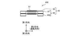
- FIG. 9 is a top view showing a state in which the first header 20 of the heat exchanger 408 according to the second embodiment is removed.
- FIG. 9 shows two adjacent heat transfer members 40 out of a large number of heat transfer members 40 arranged.
- the shape of the spacer portion 462 is different from that of the first embodiment.
- the parts common to the first embodiment are designated by the same reference numerals, the description thereof will be omitted, and the differences from the first embodiment will be mainly described.
- the spacer portion 462 As shown in FIG. 9, in the spacer portion 462, a part of the base portion 61 is bent and extends in the first direction. Unlike the first embodiment, the spacer portion 462 has a planar shape when viewed from above.
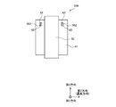
- FIG. 10 is a side view showing a method of manufacturing the heat exchanger 408 according to the second embodiment.
- the spacer portion 462 has a notch 63 in the third direction with respect to the base portion 61. That is, the spacer portion 462 is formed by bending the base portion 61 in which the notch 63 is made in the third direction in the first direction.
- the spacer portion 462 has a planar shape when viewed from above.
- the spacer portion 462 is provided at both the upper end and the lower end of the base portion 61 is illustrated, but it may be provided at either one or at another position. You may.
- the spacer portion 462 is formed by bending the base portion 61 having the notch 63 in the third direction in the first direction.
- FIG. 11 is a side view showing the heat exchanger 508 according to the third embodiment.
- the shape of the spacer portion 562 is different from that of the first and second embodiments.
- the parts common to the first and second embodiments are designated by the same reference numerals, the description thereof will be omitted, and the differences from the first and second embodiments will be mainly described.
- the spacer portion 562 is formed by cutting a part of the base portion 61 and extending in the first direction.
- the spacer portion 562 has a notch 63 in the second direction with respect to the base portion 61.
- the spacer portion 562 is provided at the upper portion of the base portion 61 in the third direction, it may be provided at the lower portion or at the central portion.
- FIG. 12 is a top view showing a state in which the first header 20 of the heat exchanger 508 according to the third embodiment is removed.
- FIG. 12 shows two heat transfer members 40 adjacent to each other among the heat transfer members 40 arranged in large numbers.
- the spacer portion 562 is provided at a position excluding the edge portion of the base portion 61, the spacer portion 562 is provided between the base portion 61 and the base portion 61 in a top view.
- the spacer portion 562 is such that a part of the base portion 61 is cut up and extends in the first direction. Therefore, since the area allocated to the spacer portion 562 is reduced, a large amount of the base portion 61 can be left. Therefore, it is possible to maintain an effective heat transfer area in the entire extending portion 60.
- FIG. 13 is a side view showing the heat exchanger 608 according to the first modification of the third embodiment.
- the spacer portion 662 has a notch 63 in the third direction in which the heat transfer tube 50 extends with respect to the base portion 61.
- the spacer portion 662 is provided at the upper portion of the base portion 61 in the third direction, it may be provided at the lower portion or at the central portion.
- FIG. 14 is a top view showing a state in which the first header 20 of the heat exchanger 608 according to the first modification of the third embodiment is removed.
- FIG. 14 shows two heat transfer members 40 adjacent to each other among the heat transfer members 40 arranged in large numbers.
- the spacer portion 662 is provided at a position excluding the edge portion of the base portion 61, the spacer portion 662 is provided between the base portion 61 and the base portion 61 in a top view.
- the spacer portion 662 is formed by cutting up a part of the base portion 61 and extending in the first direction. Therefore, since the area allocated to the spacer portion 662 is reduced, a large amount of the base portion 61 can be left. Therefore, as in the third embodiment, it is possible to maintain an effective heat transfer area in the entire extending portion 60. Further, in the spacer portion 662, the base portion 61 in which the notch 63 is made in the third direction is bent in the first direction. As a result, it is possible to receive the dew condensation water flowing down from the heat transfer tube 50. Therefore, it is possible to prevent the discharge of dew condensation water from being hindered from the heat exchanger 608.
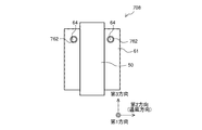
- FIG. 15 is a side view showing the heat exchanger 708 according to the second modification of the third embodiment.
- the spacer portion 762 has a burring shape formed by forming a hole 64 with respect to the base portion 61.
- the spacer portion 762 is provided at the upper portion of the base portion 61 in the third direction, it may be provided at the lower portion or at the central portion.
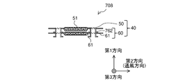
- FIG. 16 is a top view showing a state in which the first header 20 of the heat exchanger 708 according to the second modification of the third embodiment is removed.
- FIG. 16 shows two adjacent heat transfer members 40 out of a large number of heat transfer members 40 arranged.
- the spacer portion 762 is provided at a position excluding the edge portion of the base portion 61, the spacer portion 762 is provided between the base portion 61 and the base portion 61 in a top view.
- the spacer portion 762 is formed by cutting up a part of the base portion 61 and extending in the first direction. Therefore, since the area allocated to the spacer portion 762 is reduced, a large amount of the base portion 61 can be left. Therefore, as in the third embodiment, it is possible to maintain an effective heat transfer area in the entire extending portion 60.
- FIG. 17 is a top view showing a state in which the first header 20 of the heat exchanger 808 according to the fourth embodiment is removed.
- the shape of the spacer portion 862 is different from that of the first to third embodiments.
- the parts common to the first to third embodiments are designated by the same reference numerals, and the description thereof will be omitted, and the differences from the first to third embodiments will be mainly described.
- FIG. 17 shows one of the heat transfer members 40 arranged in large numbers.
- two spacer portions 862 are provided, and are provided at positions symmetrical with respect to the center of the heat transfer tube 50, and a notch 63 is made in the second direction with respect to the base portion 61.
- the spacer portion 862 on one end side of the heat transfer tube 50 extends toward one adjacent heat transfer member 40, and the spacer portion 862 on the other end side of the heat transfer tube 50 faces the other adjacent heat transfer member 40. It extends.
- two spacer portions 862 are provided, and are provided at positions symmetrical with respect to the center of the heat transfer tube 50. Therefore, during the assembly process of the heat exchanger 808, when the heat transfer tubes 50 are aligned, the shape of the spacer portion 862 is the same even if the front and back of the heat transfer tubes 50 are reversed. Therefore, when aligning the heat exchangers 808, it is not necessary to orient the plurality of heat transfer tubes 50. Therefore, the process of arranging the heat transfer tubes 50 is simplified.
- the spacer portion 862 may be a portion in which a part of the base portion 61 is bent or a portion in which a part of the base portion 61 is cut and raised.
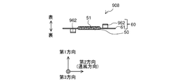
- FIG. 18 is a top view showing a state in which the first header 20 of the heat exchanger 908 according to the modified example of the fourth embodiment is removed.
- FIG. 18 shows one of the heat transfer members 40 arranged in large numbers.
- two spacer portions 962 are provided, and the heat transfer tube 50 is provided at a position symmetrical with respect to the center of the heat transfer tube 50, and the heat transfer tube 50 is provided with respect to the base 61.
- a notch 63 is made in the third direction, which is the extending direction.
- two spacer portions 962 are provided, and they are provided at positions symmetrical with respect to the center of the heat transfer tube 50. Therefore, even if the front and back of the heat transfer tube 50 are reversed when the heat transfer tubes 50 are aligned during the assembly process of the heat exchanger 908, the shape of the spacer portion 962 is the same. Therefore, when aligning the heat exchangers 908, it is not necessary to orient the plurality of heat transfer tubes 50. Therefore, the process of arranging the heat transfer tubes 50 is simplified. Further, the spacer portion 962 is obtained by bending the base portion 61 having the notch 63 in the third direction in the first direction. As a result, it is possible to receive the dew condensation water flowing down from the heat transfer tube 50. Therefore, it is possible to prevent the discharge of dew condensation water from being hindered from the heat exchanger 908.
- FIG. 19 is a front view showing the heat exchanger 1008 according to the fifth embodiment.
- the heat exchanger 1008 of the fifth embodiment is different from the first to fourth embodiments in that the spacer portion 1062 is in contact with the first header 20 and the second header 30.
- the parts common to the first to fourth embodiments are designated by the same reference numerals, and the description thereof will be omitted, and the differences from the first to fourth embodiments will be mainly described.
- the spacer portion 1062 is in contact with the first header 20 and the second header 30, and a notch 63 is made in the second direction with respect to the base portion 61.
- the spacer portion 1062 provided at the upper end portion of the base portion 61 is in contact with the first header 20, and the spacer portion 1062 provided at the lower end portion of the base portion 61 is in contact with the second header 30. ..
- the spacer portion 1062 is in contact with the first header 20 and the second header 30. It may be in contact with any of the above.
- the spacer portion 1062 is in contact with the first header 20 or the second header 30.
- the length at which both ends of the heat transfer tube 50 protrude from the spacer portion 1062 is the length of the insertion margin S of the heat transfer tube 50 in the third direction. That is, the spacer portion 1062 serves as a guide for confirming the length of the insertion margin S in the third direction when the heat transfer tube 50 is inserted into the first header 20 or the second header 30. Further, since the spacer portion 1062 is arranged at the upper end portion and the lower end portion of the base portion 61, it is possible to suppress the obstruction of the air flow.
- FIG. 20 is a front view showing the heat exchanger 1108 according to the modified example of the fifth embodiment.
- the spacer portion 1162 is in contact with the first header 20 and the second header 30. Then, in the spacer portion 1162, a notch 63 is made in the third direction in which the heat transfer tube 50 extends with respect to the base portion 61, and the portion of the base portion 61 corresponding to the notch 63 is bent in the first direction. be.
- the spacer portion 1162 is in contact with the first header 20 or the second header 30.
- the length at which both ends of the heat transfer tube 50 protrude from the spacer portion 1162 is the length of the insertion margin S of the heat transfer tube 50 in the third direction. That is, the spacer portion 1162 serves as a guide for confirming the length of the insertion margin S in the third direction when the heat transfer tube 50 is inserted into the first header 20 or the second header 30.
- the spacer portion 1162 is arranged at the upper end portion and the lower end portion of the base portion 61, it is possible to suppress obstruction of the air flow. Further, the spacer portion 1162 is obtained by bending the base portion 61 having the notch 63 in the third direction in the first direction. As a result, it is possible to receive the dew condensation water flowing down from the heat transfer tube 50. Therefore, it is possible to prevent the discharge of dew condensation water from being hindered from the heat exchanger 1108.
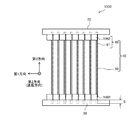
- FIG. 21 is a front view showing the heat exchanger 1208 according to the sixth embodiment.
- the heat exchanger 1208 of the sixth embodiment is different from the first to fifth embodiments in that a plurality of spacer portions 1262 are provided along the third direction.
- the parts common to the first to fifth embodiments are designated by the same reference numerals, the description thereof will be omitted, and the differences from the first to fifth embodiments will be mainly described.
- a plurality of spacer portions 1262 are provided, and are arranged at equal intervals along a third direction in which the heat transfer tube 50 extends. Further, the spacer portion 1262 has a notch 63 in the third direction, which is the direction in which the heat transfer tube 50 extends, with respect to the base portion 61.
- the spacer portions 1262 that slightly obstruct the air flow are arranged at equal intervals along the third direction, the pressure loss can be made uniform in the entire third direction. can. Therefore, it is possible to suppress the drift of air in the entire third direction. Therefore, it is possible to suppress an increase in the power of the outdoor blower 9.
- FIG. 22 is a front view showing the heat exchanger 1308 according to the modified example of the sixth embodiment.
- a plurality of spacer portions 1362 are provided, and the number on the leeward side is larger than the number on the windward side of the heat transfer tube 50.
- the spacer portion 1362 has a notch 63 in the third direction, which is the direction in which the heat transfer tube 50 extends, with respect to the base portion 61.
- two spacer portions 1362 are provided on the windward side of the heat transfer tube 50, and four spacer portions 1362 are provided on the leeward side of the heat transfer tube 50. Can be changed as appropriate.
- the spacer portion 1362 on the windward side of the heat transfer tube 50 may be omitted.
- a plurality of spacer portions 1362 are provided, and the number on the leeward side is larger than the number on the windward side of the heat transfer tube 50.
- the heat exchanger 1308 acts as an evaporator, it is more likely that frost will form on the leeward side than on the leeward side of the heat transfer tube 50.
- the total amount of frost accumulated on the spacer portion 1362 is reduced. Can be done.
Landscapes
- Engineering & Computer Science (AREA)
- Physics & Mathematics (AREA)
- Thermal Sciences (AREA)
- Mechanical Engineering (AREA)
- General Engineering & Computer Science (AREA)
- Geometry (AREA)
- Heat-Exchange Devices With Radiators And Conduit Assemblies (AREA)
Priority Applications (5)
| Application Number | Priority Date | Filing Date | Title |
|---|---|---|---|
| EP20938869.3A EP4160112A4 (en) | 2020-06-01 | 2020-06-01 | HEAT EXCHANGER AND REFRIGERATION CYCLE APPARATUS |
| CN202080101390.5A CN115667830A (zh) | 2020-06-01 | 2020-06-01 | 热交换器和制冷循环装置 |
| JP2022529136A JP7353489B2 (ja) | 2020-06-01 | 2020-06-01 | 熱交換器及び冷凍サイクル装置 |
| US17/917,617 US20230175747A1 (en) | 2020-06-01 | 2020-06-01 | Heat exchanger and refrigeration cycle apparatus |
| PCT/JP2020/021578 WO2021245734A1 (ja) | 2020-06-01 | 2020-06-01 | 熱交換器及び冷凍サイクル装置 |
Applications Claiming Priority (1)
| Application Number | Priority Date | Filing Date | Title |
|---|---|---|---|
| PCT/JP2020/021578 WO2021245734A1 (ja) | 2020-06-01 | 2020-06-01 | 熱交換器及び冷凍サイクル装置 |
Publications (1)
| Publication Number | Publication Date |
|---|---|
| WO2021245734A1 true WO2021245734A1 (ja) | 2021-12-09 |
Family
ID=78830994
Family Applications (1)
| Application Number | Title | Priority Date | Filing Date |
|---|---|---|---|
| PCT/JP2020/021578 Ceased WO2021245734A1 (ja) | 2020-06-01 | 2020-06-01 | 熱交換器及び冷凍サイクル装置 |
Country Status (5)
| Country | Link |
|---|---|
| US (1) | US20230175747A1 (https=) |
| EP (1) | EP4160112A4 (https=) |
| JP (1) | JP7353489B2 (https=) |
| CN (1) | CN115667830A (https=) |
| WO (1) | WO2021245734A1 (https=) |
Citations (12)
| Publication number | Priority date | Publication date | Assignee | Title |
|---|---|---|---|---|
| JPS53162945U (https=) * | 1977-05-30 | 1978-12-20 | ||
| JPH04198691A (ja) * | 1990-11-29 | 1992-07-20 | Toshiba Corp | 熱交換器 |
| JP2000018504A (ja) * | 1998-06-29 | 2000-01-18 | Ishikawajima Harima Heavy Ind Co Ltd | スライドスペーサ及び配管整列装置 |
| JP2002153931A (ja) * | 2000-11-21 | 2002-05-28 | Mitsubishi Heavy Ind Ltd | 熱交換チューブ及びフィンレス熱交換器 |
| JP2003247794A (ja) * | 2002-02-22 | 2003-09-05 | Toshiba Kyaria Kk | 熱交換器 |
| JP2006084078A (ja) * | 2004-09-15 | 2006-03-30 | Daikin Ind Ltd | 細径多管式熱交換器の細径伝熱管ユニット |
| US20150226495A1 (en) * | 2014-02-12 | 2015-08-13 | Lg Electronics Inc. | Heat exchanger |
| JP2016075450A (ja) * | 2014-10-09 | 2016-05-12 | 株式会社日立製作所 | 熱交換器及びこれを用いた空気調和機 |
| JP2016080325A (ja) * | 2014-10-22 | 2016-05-16 | カルソニックカンセイ株式会社 | 熱交換器 |
| JP2018162953A (ja) | 2017-03-27 | 2018-10-18 | パナソニックIpマネジメント株式会社 | 熱交換器 |
| CN110595112A (zh) * | 2019-10-30 | 2019-12-20 | 广东美的制冷设备有限公司 | 换热器和具有其的空调器 |
| WO2020012549A1 (ja) * | 2018-07-10 | 2020-01-16 | 三菱電機株式会社 | 熱交換器、熱交換装置、熱交換器ユニット及び冷凍サイクル装置 |
Family Cites Families (7)
| Publication number | Priority date | Publication date | Assignee | Title |
|---|---|---|---|---|
| JPS5628586U (https=) * | 1980-03-12 | 1981-03-17 | ||
| JPH066966U (ja) * | 1992-06-30 | 1994-01-28 | 三菱アルミニウム株式会社 | 放熱用フィン |
| JP2005299971A (ja) * | 2004-04-08 | 2005-10-27 | Matsushita Electric Ind Co Ltd | フィンアンドチューブ型熱交換器とその製造方法 |
| US20130206376A1 (en) * | 2012-02-14 | 2013-08-15 | The University Of Tokyo | Heat exchanger, refrigeration cycle device equipped with heat exchanger, or heat energy recovery device |
| US9671177B2 (en) * | 2012-04-26 | 2017-06-06 | Mitsubishi Electric Corporation | Heat exchanger, method for fabricating heat exchanger, and air-conditioning apparatus |
| WO2013160959A1 (ja) * | 2012-04-27 | 2013-10-31 | 三菱電機株式会社 | 熱交換器、その製造方法及び冷凍サイクル装置 |
| KR101694614B1 (ko) * | 2014-12-18 | 2017-01-09 | 엘지전자 주식회사 | 공기 조화기 |
-
2020
- 2020-06-01 EP EP20938869.3A patent/EP4160112A4/en not_active Withdrawn
- 2020-06-01 WO PCT/JP2020/021578 patent/WO2021245734A1/ja not_active Ceased
- 2020-06-01 CN CN202080101390.5A patent/CN115667830A/zh active Pending
- 2020-06-01 JP JP2022529136A patent/JP7353489B2/ja active Active
- 2020-06-01 US US17/917,617 patent/US20230175747A1/en not_active Abandoned
Patent Citations (12)
| Publication number | Priority date | Publication date | Assignee | Title |
|---|---|---|---|---|
| JPS53162945U (https=) * | 1977-05-30 | 1978-12-20 | ||
| JPH04198691A (ja) * | 1990-11-29 | 1992-07-20 | Toshiba Corp | 熱交換器 |
| JP2000018504A (ja) * | 1998-06-29 | 2000-01-18 | Ishikawajima Harima Heavy Ind Co Ltd | スライドスペーサ及び配管整列装置 |
| JP2002153931A (ja) * | 2000-11-21 | 2002-05-28 | Mitsubishi Heavy Ind Ltd | 熱交換チューブ及びフィンレス熱交換器 |
| JP2003247794A (ja) * | 2002-02-22 | 2003-09-05 | Toshiba Kyaria Kk | 熱交換器 |
| JP2006084078A (ja) * | 2004-09-15 | 2006-03-30 | Daikin Ind Ltd | 細径多管式熱交換器の細径伝熱管ユニット |
| US20150226495A1 (en) * | 2014-02-12 | 2015-08-13 | Lg Electronics Inc. | Heat exchanger |
| JP2016075450A (ja) * | 2014-10-09 | 2016-05-12 | 株式会社日立製作所 | 熱交換器及びこれを用いた空気調和機 |
| JP2016080325A (ja) * | 2014-10-22 | 2016-05-16 | カルソニックカンセイ株式会社 | 熱交換器 |
| JP2018162953A (ja) | 2017-03-27 | 2018-10-18 | パナソニックIpマネジメント株式会社 | 熱交換器 |
| WO2020012549A1 (ja) * | 2018-07-10 | 2020-01-16 | 三菱電機株式会社 | 熱交換器、熱交換装置、熱交換器ユニット及び冷凍サイクル装置 |
| CN110595112A (zh) * | 2019-10-30 | 2019-12-20 | 广东美的制冷设备有限公司 | 换热器和具有其的空调器 |
Also Published As
| Publication number | Publication date |
|---|---|
| US20230175747A1 (en) | 2023-06-08 |
| EP4160112A4 (en) | 2023-07-26 |
| JP7353489B2 (ja) | 2023-09-29 |
| CN115667830A (zh) | 2023-01-31 |
| JPWO2021245734A1 (https=) | 2021-12-09 |
| EP4160112A1 (en) | 2023-04-05 |
Similar Documents
| Publication | Publication Date | Title |
|---|---|---|
| CN103348211B (zh) | 热交换器及空调装置 | |
| JP6734002B1 (ja) | 熱交換器および冷凍サイクル装置 | |
| CN104285118A (zh) | 换热器、换热器的制造方法以及空调机 | |
| WO2013161802A1 (ja) | 熱交換器、及び空気調和機 | |
| US11788799B2 (en) | Heat exchanger and air conditioner | |
| JP2011127831A (ja) | 熱交換器及びこれを備えた冷凍サイクル装置 | |
| JP7292510B2 (ja) | 熱交換器及び空気調和機 | |
| WO2019009158A1 (ja) | 熱交換器 | |
| CN218270316U (zh) | 插片式微通道换热器及空调器 | |
| US11384997B2 (en) | Heat exchanger, heat exchanger unit, and refrigeration cycle apparatus | |
| WO2023170834A1 (ja) | 熱交換器及び該熱交換器を備えた冷凍サイクル装置 | |
| CN114174757A (zh) | 热交换器、其制造方法以及空调装置 | |
| JP6719657B2 (ja) | 熱交換器および冷凍サイクル装置 | |
| WO2020012549A1 (ja) | 熱交換器、熱交換装置、熱交換器ユニット及び冷凍サイクル装置 | |
| JP2019158215A (ja) | 空気調和機及び熱交換器 | |
| JP7353489B2 (ja) | 熱交換器及び冷凍サイクル装置 | |
| JP7668878B2 (ja) | 熱交換器、冷凍サイクル装置および熱交換器の製造方法 | |
| WO2024089927A1 (ja) | 熱交換器およびこの熱交換器を備えた冷凍サイクル装置 | |
| JP2012154491A (ja) | 空気調和機 | |
| CN118871738A (zh) | 热交换器、搭载有热交换器的空调机以及热交换器的制造方法 | |
| JP7675951B1 (ja) | 熱交換器及び空気調和装置 | |
| JP2012154495A (ja) | 熱交換器及び空気調和機 | |
| JP7756833B1 (ja) | 熱交換器及び空気調和装置 | |
| JP7654177B1 (ja) | 熱交換器及び空気調和装置 | |
| JP2008082619A (ja) | 熱交換器 |
Legal Events
| Date | Code | Title | Description |
|---|---|---|---|
| 121 | Ep: the epo has been informed by wipo that ep was designated in this application |
Ref document number: 20938869 Country of ref document: EP Kind code of ref document: A1 |
|
| ENP | Entry into the national phase |
Ref document number: 2022529136 Country of ref document: JP Kind code of ref document: A |
|
| NENP | Non-entry into the national phase |
Ref country code: DE |
|
| ENP | Entry into the national phase |
Ref document number: 2020938869 Country of ref document: EP Effective date: 20230102 |