WO2021241015A1 - 撮像装置、撮像方法 - Google Patents
撮像装置、撮像方法 Download PDFInfo
- Publication number
- WO2021241015A1 WO2021241015A1 PCT/JP2021/014669 JP2021014669W WO2021241015A1 WO 2021241015 A1 WO2021241015 A1 WO 2021241015A1 JP 2021014669 W JP2021014669 W JP 2021014669W WO 2021241015 A1 WO2021241015 A1 WO 2021241015A1
- Authority
- WO
- WIPO (PCT)
- Prior art keywords
- read
- reading
- pixel
- image
- image pickup
- Prior art date
- Legal status (The legal status is an assumption and is not a legal conclusion. Google has not performed a legal analysis and makes no representation as to the accuracy of the status listed.)
- Ceased
Links
Images


Classifications
-
- H—ELECTRICITY
- H04—ELECTRIC COMMUNICATION TECHNIQUE
- H04N—PICTORIAL COMMUNICATION, e.g. TELEVISION
- H04N25/00—Circuitry of solid-state image sensors [SSIS]; Control thereof
- H04N25/40—Extracting pixel data from image sensors by controlling scanning circuits, e.g. by modifying the number of pixels sampled or to be sampled
- H04N25/44—Extracting pixel data from image sensors by controlling scanning circuits, e.g. by modifying the number of pixels sampled or to be sampled by partially reading an SSIS array
-
- H—ELECTRICITY
- H04—ELECTRIC COMMUNICATION TECHNIQUE
- H04N—PICTORIAL COMMUNICATION, e.g. TELEVISION
- H04N25/00—Circuitry of solid-state image sensors [SSIS]; Control thereof
- H04N25/70—SSIS architectures; Circuits associated therewith
- H04N25/703—SSIS architectures incorporating pixels for producing signals other than image signals
- H04N25/704—Pixels specially adapted for focusing, e.g. phase difference pixel sets
-
- G—PHYSICS
- G02—OPTICS
- G02B—OPTICAL ELEMENTS, SYSTEMS OR APPARATUS
- G02B7/00—Mountings, adjusting means, or light-tight connections, for optical elements
- G02B7/28—Systems for automatic generation of focusing signals
-
- G—PHYSICS
- G02—OPTICS
- G02B—OPTICAL ELEMENTS, SYSTEMS OR APPARATUS
- G02B7/00—Mountings, adjusting means, or light-tight connections, for optical elements
- G02B7/28—Systems for automatic generation of focusing signals
- G02B7/34—Systems for automatic generation of focusing signals using different areas in a pupil plane
-
- G—PHYSICS
- G03—PHOTOGRAPHY; CINEMATOGRAPHY; ANALOGOUS TECHNIQUES USING WAVES OTHER THAN OPTICAL WAVES; ELECTROGRAPHY; HOLOGRAPHY
- G03B—APPARATUS OR ARRANGEMENTS FOR TAKING PHOTOGRAPHS OR FOR PROJECTING OR VIEWING THEM; APPARATUS OR ARRANGEMENTS EMPLOYING ANALOGOUS TECHNIQUES USING WAVES OTHER THAN OPTICAL WAVES; ACCESSORIES THEREFOR
- G03B13/00—Viewfinders; Focusing aids for cameras; Means for focusing for cameras; Autofocus systems for cameras
- G03B13/32—Means for focusing
- G03B13/34—Power focusing
- G03B13/36—Autofocus systems
-
- H—ELECTRICITY
- H04—ELECTRIC COMMUNICATION TECHNIQUE
- H04N—PICTORIAL COMMUNICATION, e.g. TELEVISION
- H04N25/00—Circuitry of solid-state image sensors [SSIS]; Control thereof
- H04N25/40—Extracting pixel data from image sensors by controlling scanning circuits, e.g. by modifying the number of pixels sampled or to be sampled
-
- H—ELECTRICITY
- H04—ELECTRIC COMMUNICATION TECHNIQUE
- H04N—PICTORIAL COMMUNICATION, e.g. TELEVISION
- H04N25/00—Circuitry of solid-state image sensors [SSIS]; Control thereof
- H04N25/50—Control of the SSIS exposure
- H04N25/53—Control of the integration time
- H04N25/531—Control of the integration time by controlling rolling shutters in CMOS SSIS
-
- H—ELECTRICITY
- H04—ELECTRIC COMMUNICATION TECHNIQUE
- H04N—PICTORIAL COMMUNICATION, e.g. TELEVISION
- H04N25/00—Circuitry of solid-state image sensors [SSIS]; Control thereof
- H04N25/70—SSIS architectures; Circuits associated therewith
- H04N25/703—SSIS architectures incorporating pixels for producing signals other than image signals
- H04N25/706—Pixels for exposure or ambient light measuring
Definitions
- the present technology relates to an image pickup apparatus and an image pickup method provided with an image pickup element having a pixel group for outputting a phase difference signal.
- Some image pickup devices have a function of acquiring focus information about a subject in order to perform autofocus control.
- Such an image pickup device is known to include, for example, a pixel for detecting a focus.
- a pixel for detecting a focus In Patent Document 1, a plurality of image signals whose pupils are divided by an image sensor are read out to perform focus detection, and a read line for acquiring a plurality of image signals is controlled to set the accumulation time or sensitivity of the image sensor.
- a technique for changing the read row of the focus detection pixel accordingly is disclosed.
- the image pickup device has an image pickup element provided with a photodiode divided pixel and all pixels to be image-generated as a read corresponding to one frame of an image when the rolling shutter is read out from the image pickup element.
- the first read to read the added value of the first pixel and the second pixel constituting the photodiode divided pixel, and the value of the first pixel and the first pixel of some of the pixels to be image-generated.
- the second read which can obtain the value of two pixels, is controlled to be performed in a time division, and the exposure period for the first read and the exposure period for the second read are separately provided.
- a control unit and a control unit are provided.
- the photodiode divided pixel becomes a pixel used for image generation by reading out the added value of the first pixel and the second pixel.
- a second read is performed separately from the first read.
- a process of generating an image based on the added value obtained by the first read is performed, and the value of the first pixel obtained by the second read and the second read are performed. It is conceivable to perform phase difference detection processing using the pixel values. As the first read, the read for image generation is performed, and as the second read, the read for phase difference detection is performed.
- control unit executes the second reading after the first reading is completed as the reading corresponding to one frame of the image. For example, the first read is performed for image generation, and then the second read is performed for focus control in subsequent frames.
- the control unit executes the first reading after the second reading is completed as the reading corresponding to one frame of the image. For example, first, a second read is performed for focus control in a subsequent frame, and then a second read is performed for image generation.
- control unit may start the exposure for the second reading before the first reading is completed. Even during the first reading, the line for which the reading has been completed can be exposed, so the exposure for the second reading is started.
- control unit may end the second reading during the exposure for the first reading. That is, the second read is performed in parallel with the exposure for the first read, and ends during the exposure period for the first read.
- the reading of one of the first pixel and the second pixel and the reading of the added value of the first pixel and the second pixel are performed.
- the value of the other pixel can be calculated, and the value of the first pixel and the value of the second pixel can be obtained, respectively.
- the image pickup element receives a light-shielding portion that blocks one of a pair of light fluxes that have passed through a pair of partial regions that are biased in opposite directions in a predetermined direction in an exit pupil and a light-receiving part of the other. It has a light-shielding pixel having a pupil division function by being provided with a light-receiving element, and the control unit controls so that a third read to read the light-shielding pixel is performed, and the light-shielding pixel obtained by the third read is performed. It is conceivable that the phase difference detection process is performed using the value of.
- the light-shielding pixels include, for example, a pixel in which only light that has passed through a left-hand region designated by the light-shielding portion as the left half region of the exit pupil is incident, and a right-hand region defined by the light-shielding portion as the right half region of the exit pupil. It is one of the pixels to which only the light that has passed is incident.
- the third read is performed before the second read as the read corresponding to one frame of the image.
- the reading of the light-shielding pixel as the third reading and the second reading are performed before and after in time division.
- the second read is performed before the third read as the read corresponding to one frame of the image.
- the second read and the read of the light-shielding pixel as the third read are performed before and after in a time division manner.
- the third read is performed together with the first read.
- the photodiode divided pixel is used as a pixel for pixel generation, and when the pixel is read, the light-shielding pixel is also read.
- focus control is performed using the result of the phase difference detection processing based on the second read and the result of the phase difference detection process based on the third read, whichever is more reliable. It is possible to do it. Focus control is performed by selectively using either the defocus amount calculated as the phase difference detection result by the light-shielding pixel or the defocus amount calculated as the phase difference detection result by the photodiode divided pixel.
- the thinning rate for setting some pixels to be read in the second readout is variably set.
- the values of the first pixel and the second pixel are obtained from the thinned pixels and used for the autofocus control, and the thinning rate is changed according to various conditions.
- the first read and the second read are time-divisioned when the still image continuous shooting is performed.
- the first reading and the second reading are performed in a time division as the processing of each frame to be continuously shot and captured.
- the image pickup method is an image pickup method of an image pickup apparatus provided with an image pickup element provided with photodiode divided pixels.
- the rolling shutter is read from the image sensor, the added value of the first pixel and the second pixel constituting the photodiode divided pixel for all the pixels to be image-generated as the reading corresponding to one frame of the image.
- the first read, which reads out the image, and the second read, which can obtain the value of the first pixel and the value of the second pixel for some of the pixels to be image-generated, are performed in a time-divided manner.
- the exposure period for the first reading and the exposure period for the second reading are separately provided. As a result, an image pickup device that performs the first reading and the second reading separately is realized.
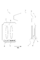
- Imaging device configuration> 1 and 2 show the appearance of the image pickup apparatus 1 according to the present embodiment.
- the subject side is the front and the imager side is the rear, but these directions are for convenience of explanation and are limited to these directions with respect to the implementation of the present technology. There is no.
- the image pickup apparatus 1 is a lens mirror that can be attached to and detached from the camera housing 2 in which the required parts are arranged inside and outside and the camera housing 2 and is attached to the front portion 2a.
- a cylinder 3 is provided.
- the lens barrel 3 is detachable as a so-called interchangeable lens as an example, and may be a lens barrel that cannot be removed from the camera housing 2.
- a rear monitor 4 is arranged on the rear surface portion 2b of the camera housing 2.
- the rear monitor 4 displays a live view image, a reproduced image of the recorded image, and the like.
- the rear monitor 4 is a display device such as a liquid crystal display (LCD) or an organic EL (Electro-Luminescence) display, for example.
- the rear monitor 4 is rotatable with respect to the camera housing 2.
- the lower end of the rear monitor 4 can be rotated around the upper end of the rear monitor 4 as a rotation axis so that the lower end of the rear monitor 4 moves rearward.
- the right end portion and the left end portion of the rear monitor 4 may be a rotation axis. Further, it may be rotatable in a plurality of axial directions.
- An EVF (Electric Viewfinder) 5 is arranged on the upper surface portion 2c of the camera housing 2.
- the EVF 5 includes an EVF monitor 5a and a frame-shaped enclosure 5b projecting rearward so as to surround the upper side and the left and right sides of the EVF monitor 5a.
- the EVF monitor 5a is formed by using an LCD, an organic EL display, or the like.
- An optical finder OVF: Optical View Finder
- Various controls 6 are provided on the rear surface portion 2b and the upper surface portion 2c.
- Examples of the operator 6 include a playback menu start button, an enter button, a cross key, a cancel button, a zoom key, a slide key, a shutter button 6S (release button), and the like.
- Various controls 6 include various modes such as buttons, dials, pressing and rotatable compound controls.
- the controls 6 in various modes enable, for example, menu operation, playback operation, mode selection / switching operation, focus operation, zoom operation, and parameter selection / setting such as shutter speed and F value.
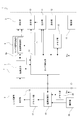
- FIG. 3 shows the internal configuration of such an image pickup device 1. Further, FIG. 4 shows an arrangement example of a part of the configuration of FIG.
- the lens barrel 3 includes an optical system 16, a driver unit 17, a lens barrel control unit 18, an operation unit 19, a memory unit 20, and the like.
- the optical system 16 includes various lenses such as an incident end lens, a zoom lens, a focus lens, and a condenser lens, and a lens or an iris (so that sensing is performed while the signal charge is not saturated and is within the dynamic range. It is equipped with a diaphragm mechanism that controls exposure by adjusting the aperture amount by the diaphragm) and a shutter unit such as a focal plane shutter. A part of each part constituting the optical system 16 may be provided in the camera housing 2.
- the image sensor 7 is, for example, a CCD (Charge Coupled Device) type or a CMOS (Complementary Metal-Oxide Semiconductor) type, and controls the exposure of light from a subject incident on the optical system 16.
- the electric signal photoelectrically converted by the pixels is provided with a processing unit that performs, for example, CDS (Correlated Double Sampling) processing, AGC (Automatic Gain Control) processing, and A / D (Analog / Digital) conversion processing. Therefore, the image sensor 7 outputs the captured image signal as digital data to the camera signal processing unit 8 and the camera control unit 14.
- the sensor surface of the image pickup element 7 is configured to have a sensing element in which a plurality of pixels are two-dimensionally arranged. As shown in FIG. 5, the image pickup device 7 is formed by arranging PD division pixels 21 on a matrix in the row direction and the column direction. Each PD divided pixel 21 is composed of two divided pixels.
- the configuration of the PD division pixel 21 is schematically shown in FIG.
- the PD division pixel 21 includes two division pixels, that is, a left PD40L as a left division pixel, a right PD40R as a right division pixel, a pixel boundary metal 41 arranged in front of the left PD40L, and an inner lens 32. , A color filter 33 and an on-chip microlens 34.
- the color filter 33 is either a color filter 33R having a red (R) spectral sensitivity, a color filter 33G having a green (G) spectral sensitivity, or a color filter 33B having a blue (B) spectral sensitivity. ..
- the inner lens 32 or the like is not provided.
- the left PD40L receives light that has passed through the right pupil region EPR of the exit pupil EP.
- the right PD40R receives light that has passed through the left pupil region EPL. This realizes the pupil division function.
- Such PD division pixels 21 are arranged as R pixels, G pixels, and B pixels as shown in FIG. 5 due to the difference in the color filter 33.
- the signal obtained as the added value of the left PD40L and the right PD40R becomes the signal of one G pixel.
- the phase difference detection can be performed by the values of the left PD40L and the right PD40R.
- the camera signal processing unit 8 is composed of, for example, a microcomputer specialized in digital signal processing such as a DSP (Digital Signal Processor), a microcomputer, or the like.
- a microcomputer specialized in digital signal processing such as a DSP (Digital Signal Processor), a microcomputer, or the like.
- the camera signal processing unit 8 performs various signal processing on the digital signal (image pickup image signal) sent from the image pickup element 7. Specifically, processing such as correction processing between R, G, and B color channels, white balance correction, aberration correction, and shading correction is performed. Further, the camera signal processing unit 8 generates (separates) a luminance (Y) signal and a color (C) signal from the image data of R, G, and B, a YC generation process, a process of adjusting the luminance and the color, and a knee. Perform each process such as correction and gamma correction. Further, the camera signal processing unit 8 performs conversion to the final output format by performing resolution conversion processing, codec processing for coding for recording and communication, and the like.
- the image data converted into the final output format is stored in the memory unit 15. Further, by outputting the image data to the display unit 10, the image is displayed on the rear monitor 4 and the EVF monitor 5a. Further, by outputting from the external output terminal, it is displayed on a device such as a monitor provided outside the image pickup apparatus 1.
- the camera signal processing unit 8 includes a phase difference detection unit 8a.
- the phase difference detection unit 8a performs phase difference detection from the output signals of the left PD40L and the right PD40R of the PD division pixel 21. Then, the phase difference detection unit 8a calculates the defocus amount based on the detected phase difference information.
- the calculated defocus amount may be used for the autofocus (AF) function by being used for driving the focus lens included in the optical system 16 via the lens barrel control unit 18. Further, the defocus amount may be used to present information regarding the focus condition of the subject to the user.
- AF autofocus
- the recording unit 9 is composed of, for example, a non-volatile memory, and stores an image file (content file) such as still image data and moving image data, attribute information of the image file, a thumbnail image, and the like.
- the image file is stored in a format such as JPEG (Joint Photographic Experts Group), TIFF (Tagged Image File Format), GIF (Graphics Interchange Format), or the like.
- the actual form of the recording unit 9 can be considered in various ways.
- the recording unit 9 may be configured as a flash memory built in the image pickup device 1, or may be stored in or read from a memory card (for example, a portable flash memory) that can be attached to and detached from the image pickup device 1 and the memory card. It may be composed of an access unit that performs access for. Further, it may be realized as an HDD (Hard Disk Drive) or the like as a form built in the image pickup apparatus 1.
- HDD Hard Disk Drive
- the display unit 10 executes processing for performing various displays on the imager.
- the display unit 10 is, for example, a rear monitor 4 or an EVF monitor 5a.
- the display unit 10 performs a process of displaying image data converted to an appropriate resolution input from the camera signal processing unit 8.
- a live view image also referred to as a through image
- the display unit 10 realizes on the screen the display of various operation menus, icons, messages, etc. as a GUI (Graphical User Interface) based on the instruction from the camera control unit 14.
- the display unit 10 can display a reproduced image of the image data read from the recording medium in the recording unit 9.
- both the EVF monitor 5a and the rear monitor 4 are provided, but the implementation of the present technology is not limited to such a configuration, and only one of the EVF monitor 5a and the rear monitor 4 is provided. May be provided, or either one or both of the EVF monitor 5a and the rear monitor 4 may be detachable.
- the output unit 11 performs data communication and network communication with an external device by wire or wirelessly. For example, captured image data (still image file or moving image file) is transmitted to an external display device, recording device, playback device, or the like. Further, the output unit 11 may function as a network communication unit. For example, communication may be performed by various networks such as the Internet, a home network, and a LAN (Local Area Network), and various data may be transmitted and received to and from a server, a terminal, or the like on the network.
- networks such as the Internet, a home network, and a LAN (Local Area Network)
- the operation unit 12 provided in the camera housing 2 includes not only the various controls 6 described above but also a rear monitor 4 that employs a touch panel method, and various operations such as tap operation and swipe operation of the imager.
- the operation information according to the above is output to the camera control unit 14.
- the operation unit 12 may function as a reception unit for an external operation device such as a remote controller that is separate from the image pickup device 1.
- the power supply unit 13 generates a power supply voltage (Vcc) required for each unit from, for example, a battery filled inside, and supplies it as an operating voltage.
- Vcc power supply voltage
- the power supply voltage Vcc by the power supply unit 13 is also supplied to the circuit in the lens barrel 3. Even if the power supply unit 13 is formed with a circuit for charging the battery or a circuit for generating the power supply voltage Vcc using the DC voltage converted and input by the AC adapter connected to the commercial AC power supply as the power supply. good.
- the camera control unit 14 is composed of a microcomputer (arithmetic processing device) provided with a CPU (Central Processing Unit), and controls the image pickup device 1 in an integrated manner. For example, the shutter speed is controlled according to the operation of the imager, the camera signal processing unit 8 gives instructions for various signal processing, the image pickup operation and the recording operation are performed according to the user's operation, and the recorded image file is reproduced.
- the camera control unit 14 switches various shooting modes and the like.
- the various shooting modes include, for example, a still image shooting mode, a moving image shooting mode, and a continuous shooting mode for continuously acquiring still images.
- the camera control unit 14 includes a user interface control unit (UI control unit) 14a for enabling the user to operate these functions.
- the UI control unit 14a performs a process of detecting an operation on each operator 6 provided in the image pickup apparatus 1, a display process on the rear monitor 4, an operation detection process, and the like.
- the camera control unit 14 gives an instruction to the lens barrel control unit 18 in order to control various lenses included in the optical system 16. For example, a process of designating an aperture value in order to secure a necessary amount of light for AF control, an operation instruction of an aperture mechanism according to the aperture value, and the like are performed.
- the camera control unit 14 can acquire information about various lenses included in the optical system 16 via the lens barrel control unit 18.
- the lens information includes, for example, lens model number, zoom lens position, F-number information, exit pupil position information, and the like. Further, the camera control unit 14 is capable of acquiring the aperture value of the aperture mechanism included in the optical system 16.
- the memory unit 15 stores information and the like used for processing executed by the camera control unit 14.
- a ROM Read Only Memory
- RAM Random Access Memory
- flash memory and the like are comprehensively shown.
- the memory unit 15 may be a memory area built in the microcomputer chip as the camera control unit 14, or may be configured by a separate memory chip.
- Programs and the like used by the camera control unit 14 are stored in the ROM, flash memory, and the like of the memory unit 15.
- ROM, flash memory, etc. in addition to content files such as an OS (Operating System) for the CPU to control each part and an image file, application programs and firmware for various operations are stored.
- the camera control unit 14 controls the entire image pickup apparatus 1 and the lens barrel 3 by executing the program.
- the RAM of the memory unit 15 is used as a work area of the camera control unit 14 by temporarily storing data, programs, and the like used in various data processing executed by the CPU of the camera control unit 14.
- the lens barrel control unit 18 of the lens barrel 3 is configured by, for example, a microcomputer, and outputs a control signal to the driver unit 17 in order to actually drive various lenses of the optical system 16 based on the instruction of the camera control unit 14. I do.
- Information communication between the camera control unit 14 and the lens barrel control unit 18 may be possible only when the lens barrel 3 is mounted on the camera housing 2, or the lens barrel can be communicated by wireless communication. It may be possible in a state where 3 is not attached to the camera housing 2.
- the lens barrel control unit 18 transmits information on the exit pupil position and the pupil distance of the exit pupil to the camera control unit 14 based on the types and drive positions of various lenses included in the optical system 16. Specifically, the information regarding the pupil distance is acquired from the information stored in the ROM as the memory unit 20 and transmitted to the camera control unit 14.
- the driver unit 17 is provided with, for example, a motor driver for the zoom lens drive motor, a motor driver for the focus lens drive motor, an aperture mechanism driver for the motor that drives the aperture mechanism, and the like. Each driver supplies a drive current to the corresponding drive motor in response to an instruction from the lens barrel control unit 18.
- the operation unit 19 of the lens barrel 3 indicates an operator provided on the lens barrel 3 side.
- the operation information by the operation unit 19 is supplied to the lens barrel control unit 18, and is notified to the camera control unit 14 via the lens barrel control unit 18.
- the lens barrel control unit 18 controls the operation of the optical system 16, and the camera control unit 14 performs various settings and operation control.
- the operation unit 19 may function as a reception unit for an external operation device such as a remote controller that is separate from the lens barrel 3.
- the memory unit 20 is composed of a ROM, a flash memory, or the like, and stores programs, data, and the like used by the lens barrel control unit 18.
- the memory unit 20 stores an OS (Operating System) for the CPU to control each unit, application programs and firmware for various operations, and the like. Further, the information stored in the memory unit 20 includes information such as the pupil distance of the exit pupil of the optical system 16.
- each PD divided pixel 21 can not only read the pixel signal for image generation but also the left and right.
- the pixel value of PD can be obtained separately to obtain a phase difference signal.
- the amount of defocus can be calculated from this phase difference signal, and AF (autofocus) control can be executed.
- AF autofocus
- (L + R) read refers to read by adding charges from the left PD40L and the right PD40R.
- L read refers to charge reading from the left PD40L
- R reading refers to charge reading from the right PD40R
- L value is a pixel signal value obtained by directly reading or calculating from the left PD40L
- R value is a pixel signal value obtained by directly reading or calculating from the right PD40R.
- the (L + R) value is an addition value of the pixel signal values of the left PD40L and the right PD40R.
- the (L + R) value that is, the added value of the charges of the left PD40L and the right PD40R has a meaning as the pixel value of the PD divided pixel 21, and is therefore a signal used for image generation. Further, L reading is performed to obtain a signal value (L value) of the left PD40L, and (L + R) ⁇ L obtains an R value which is a signal value of the right PD40R.
- the phase difference of the pixel component divided into pupils can be obtained from this "L value” R value ", and AF control can be performed based on this.
- the (L + R) reading is to obtain the pixel value, it is performed from all the PD division pixels 21 of the image generation target. Normally, (L + R) reading is performed for the PD divided pixels 21 of all the horizontal lines as effective pixels, for example.
- the PD division pixels 21 to be image-generated may be a part of the pixels after they are thinned out, but in any case, (L + R) is read out for all the PD division pixels 21 required for image generation. I do.
- the purpose of AF control is to perform L reading, it is not always necessary to perform L reading for all pixels (that is, all pixels as image generation targets). If L-reading is performed for all the pixels, the reading process is performed twice for all the horizontal lines including such pixels, and the reading time of 1V becomes long. For this reason, it may be disadvantageous in terms of the number of frames for continuous shooting.
- L reading is performed for some of the thinned out pixels. For example, for a part of the horizontal lines, L read and (L + R) read are performed for the PD divided pixel 21 of the horizontal line, and (L + R) read is performed only for the PD divided pixel 21 in the other horizontal lines.
- FIG. 7 schematically shows such a reading operation.
- FIG. 7 shows the reading timing of each horizontal line when the vertical axis is the horizontal line number as the straight line SL10 in the vertical period (V1, V2 ...) defined by the vertical synchronization signal XVS.
- the first horizontal line number is "HL1" and the last horizontal line number is "HLmax”.
- reading is performed sequentially from the first horizontal line (L1) to the last horizontal line (Lmax).
- ⁇ is marked on the straight line SL10 at intervals of the periods of a plurality of horizontal lines. It is shown that the PD division pixel 21 of the horizontal line in the portion marked with ⁇ is read twice, and the PD division pixel 21 of the horizontal line corresponding to the solid line portion is normally read.
- normal reading means performing (L + R) reading once
- double reading means performing L reading and (L + R) reading.
- AF detection is performed based on the L value and R value of the PD divided pixel 21 that has been read twice, and the lens is driven according to the result. As a result, for example, the AF control is reflected in the next vertical period.
- FIG. 8 shows the exposure operation and the reading operation (hatched portion) of a part of the horizontal lines (horizontal lines HL1, HL2, HL3, ... HLn, HLn + 1, HLn + 2 ... HLm, HLm + 1, HLm + 2) in the straight line SL10. Shows. At each horizontal line, exposure is performed for a predetermined time, and then the charge is read out. Here, it is assumed that the horizontal line HLn + 1 is a line marked with ⁇ in FIG. In FIG. 8, each horizontal line other than the horizontal line HLn + 1 is read only (L + R) as a normal read. On the horizontal line HLn + 1, two readings are performed, one for L reading and the other for (L + R) reading.
- phase difference detection can be performed without significantly lengthening the 1V period.
- a phenomenon occurs in which the edge of a moving subject looks unnatural on the image.
- the portion of the horizontal line HLn + 1 read twice and the portion before and after the horizontal line are misaligned, but the imager is above. This is because such a deviation is repeated a plurality of times when reading from the bottom to the bottom, and it looks like a zigzag line. Therefore, in the embodiment, a reading operation is realized so that such a periodic image edge shift does not occur.
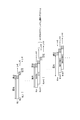
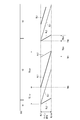
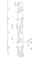
- FIG. 9 has a time axis in the horizontal direction and shows vertical periods V1, V2, and V3 defined by the vertical synchronization signal XVS.
- V1, V2, V3 For example, it is assumed that the release operation is performed in the continuous shooting mode and the continuous shooting imaging is performed. In each vertical period, one image constituting the continuous shooting image is captured.
- the vertical axis is a horizontal line number (from “HL1” to "HLmax"), and solid lines RL1 and RL2 and broken lines EL1 and EL2 are shown.
- the solid lines RL1 and RL2 indicate the reading timing for each horizontal line
- the broken lines EL1 and EL2 indicate the exposure start timing for each horizontal line.
- the interval between the broken line EL1 and the solid line RL1 and the interval between the broken line EL2 and the solid line RL2 are the exposure periods.
- the vertical period V2 will be mainly described. Exposure is sequentially started from the first horizontal line (HL1) to the last horizontal line (HLmax) at the timing indicated by the broken line EL1. After that, as shown by the solid line RL1 parallel to the broken line EL1, reading is sequentially performed from the time point TM0 from the first horizontal line (HL1) to the last horizontal line (HLmax).
- the fact that the broken line EL1 and the solid line RL1 are parallel means that each horizontal line from the beginning to the end is exposed for the time length indicated as the exposure period Tenor, and then the exposure is performed.
- the period during which the read operation of the solid line RL1 is performed is the read period TRnor.
- This read period TRnor is a period during which the first read is executed. That is, (L + R) reading is performed once for each horizontal line.
- FIG. 10A schematically shows the operation of the first reading. Charge reading of L value + R value is performed from each horizontal line.
- the exposure is started as shown by the broken line EL2.
- This is the exposure for the subsequent second readout, and targets the PD division pixel 21 of a part of the horizontal lines.
- a horizontal line is periodically selected at a predetermined thinning rate, for example, one in 10 horizontal lines, and a second read is performed. For example, if the horizontal lines HL1, HL11, HL21, and the like are selected, the exposure of the horizontal line HL1 is started at the time point TM1, and thereafter, the exposure is sequentially started at the timing indicated by the broken line EL2.
- the reason why the broken line EL2 has a larger inclination than the broken line EL1 is that the number of target horizontal lines is small.
- the thinning rate for selecting the horizontal line HL to be read second may be changed. For example, it may be changed according to the brightness.
- the reading period TRnor has not ended at the time TM1 at the start of exposure indicated by the broken line EL2, but the horizontal line to be exposed is set to be the horizontal line for which the first reading has already been completed.
- the time point TM1 at which the exposure of the broken line EL2 is started is set so that the exposure of the last horizontal line (HLmax) is started immediately after the first reading of the last horizontal line (HLmax) is completed.
- the exposure is sequentially started at each horizontal line after the thinning. Then, from the time point TM2, as shown by the solid line RL2 parallel to the broken line EL2, each exposed horizontal line is sequentially read out.
- each horizontal line is exposed for the time length indicated as the exposure period TEpd, and then the reading is performed.
- the period during which the reading operation of the solid line RL2 is performed is the reading period TRpd.
- This read period TRpd is a period during which the second read is executed. That is, each horizontal line is read twice, L read and (L + R) read.
- FIG. 10B schematically shows the operation of the second reading. L read and (L + R) read are performed from some horizontal lines selected after decimation. For the reading, for example, after reading the L value from the left PD40L, a process of reading the image signal of the right PD40R is performed without resetting the charge. That is, after reading the L value, the L value and the R value are added in the FD (floating diffusion) unit in the image sensor so that the (L + R) value is read out.
- FD floating diffusion
- the exposure for the first reading of the next vertical period V3 shown as the broken line EL1 is started. This is because the horizontal line (and the thinned horizontal line) where the second reading is performed may start the exposure.
- the first read that reads (L + R) from all the PD division pixels 21 to be image-generated, and L for some pixels after thinning out.
- the second read which performs the read and the (L + R) read, is performed in a time-division manner. Further, an exposure period for the first reading (broken line EL1) and an exposure period for the second reading (broken line EL2) are separately provided. In this case, in the first reading shown by the solid line RL1, the reading is not performed twice in some horizontal lines, so that the edge is unnatural to the image as described in the comparative examples of FIGS. 7 and 8. Is resolved. Then, it is possible to perform phase difference detection based on the second readout and perform AF control.
- FIG. 9 The reading operation as shown in FIG. 9 is executed based on the control of the camera control unit 14.
- FIG. 11 shows a flowchart of the reading operation based on the control of the camera control unit 14.
- FIG. 12 shows the AF process associated with the reading operation. It should be noted that these are examples assuming an imaging operation in the continuous shooting mode.
- step S101 of FIG. 11 the camera control unit 14 monitors the full press of the shutter button 6S. When the full push is not performed, other processing (not shown) is performed.
- step S101 When the full press of the shutter button 6S is detected in the continuous shooting mode, the camera control unit 14 proceeds from step S101 to step S102 to start the first reading.
- step S102 In the image pickup device 7, reading is sequentially started from the first horizontal line HL1.
- the (L + R) value read from each PD division pixel 21 in this first reading is processed as a pixel value for generating an image in the camera signal processing unit 8, and one still image data in continuous shooting is generated. ..
- the pulse timing related to the reading operation in the image sensor 7 is defined according to the parameter set by the camera control unit 14, and the first reading is started at a predetermined time point.
- the first read is started from the time point TM0 in FIG. 9, starting from the vertical synchronization signal that defines the vertical period.
- the exposure is performed up to the time point TM0.
- step S103 the camera control unit 14 starts the exposure for the second reading.
- exposure is sequentially started only for the horizontal line to be read second.
- the pulse timing for executing the exposure operation for each horizontal line in the image sensor 7 is defined according to the parameter set by the camera control unit 14, and the exposure for the second reading is started from the time point TM1 in FIG. NS.
- step S104 the camera control unit 14 starts the second reading.
- the second reading is sequentially performed only for the horizontal line to be the target of the second reading.
- the pulse timing for executing the read operation for each horizontal line in the image sensor 7 is actually defined according to the parameter set by the camera control unit 14, and the second operation after the time point TM2 in FIG. 9 is actually defined. Reading is executed.
- step S105 the camera control unit 14 starts the exposure for the first reading in the next vertical period.
- exposure is sequentially started for all the pixels (horizontal lines) to be image-generated.
- the pulse timing for executing the exposure operation is defined for each horizontal line in the image sensor 7 according to the parameter set by the camera control unit 14. In this case, it is possible to start the exposure sequentially from the leading horizontal line HL1 immediately after the second reading is started. For example, when the first horizontal line HL1 is the target of the second reading, the exposure from the horizontal line HL1 becomes possible when the second reading of the PD divided pixel 21 of the horizontal line HL1 is completed. When the leading horizontal line HL1 is not the target of the second read, the exposure for the next first read from the horizontal line HL1 becomes possible at the same time as the start of the second read.
- the pulse timing is determined in consideration of such circumstances.
- the camera control unit 14 returns to step S101, and if the shutter button 6S is fully pressed, the same process is continued.
- the camera control unit 14 exits the process of FIG. Even if the shutter button 6S is fully pressed, the process is exited when the maximum number of continuous shots is exceeded.
- AF control is performed as shown in FIG. 12 in response to the second reading in step S104.
- the L value is read for each PD divided pixel 21 in the second reading and the (L + R) value is read in the second reading, but the L value is read in the first reading. It may be read and the R value may be read a second time (or vice versa). That is, it may be read out for each divided PD. In any case, it suffices if the L value and the R value for each PD divided pixel 21 that is the target of the second reading can be obtained.
- step S205 the process proceeds to step S205, and the camera signal processing unit 8 performs phase difference detection by the function of the phase difference detection unit 8a. Then, the defocus amount is transmitted to the camera control unit 14.
- the camera control unit 14 instructs the lens barrel control unit 18 in step S206 according to the defocus amount, and causes the focus lens included in the optical system 16 to be driven. Then, in step S207, the lens drive is stopped. As a result, the AF operation is executed.
- Reading operation of the second embodiment The reading operation as the second embodiment is shown in FIG. Note that FIG. 13 and FIGS. 16, 20, and 21 described later have the same format as that of FIG. 9, assuming that the release operation is performed in the continuous shooting mode and continuous shooting imaging is performed.
- the vertical periods V1, V2, and V3 defined by the vertical synchronization signal XVS are shown. Further, thereafter, the meanings of the first read and the second read are the same as those in the first embodiment.
- the vertical period V2 will be mainly described.
- TM10 during the first reading indicated by the solid line RL1 in the vertical period V1, the exposure for the second reading shown as the broken line EL2 is started.
- TM10 is set so that the horizontal line to be exposed is the horizontal line for which the first reading has already been completed.
- each horizontal line after being thinned out is sequentially exposed, and then from the time point TM11, for each exposed horizontal line as shown by the solid line RL2 parallel to the broken line EL2. , Sequentially read.
- the interval between the broken line EL2 and the solid line RL2 is the exposure period TEpd for the second reading.
- the period during which the read operation of the solid line RL2 is performed is the read period TRpd of the second read.
- Exposure is sequentially started from the first horizontal line (HL1) to the last horizontal line (HLmax) at the timing indicated by the broken line EL1.
- reading is sequentially performed from the time point TM12 from the first horizontal line (HL1) to the last horizontal line (HLmax).
- the interval between the broken line EL1 and the solid line RL1 is the exposure period Tenor for the first reading.
- the period during which the read operation of the solid line RL1 is performed is the read period TRnor of the first read. In the middle of the read period TRnor, the exposure for the second read of the next vertical period V3 is started.
- the second read is performed first and then the first read is performed in one vertical period corresponding to one frame. Even with this, in the first reading shown by the solid line RL1, the reading is not performed twice in some horizontal lines, which is unnatural for the image as described in the comparative examples of FIGS. 7 and 8. The occurrence of edges is eliminated. Then, it is possible to perform phase difference detection based on the second readout and perform AF control.
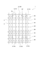
- the image pickup device 7 is of a hybrid type having a PD division pixel 21 and a light shielding pixel 23.
- FIG. 14 shows an example of pixel arrangement of the image pickup device 7.
- the first pixel row 22A a pixel row having light-shielding pixels 23 is formed.
- the first pixel row 22A is discretely arranged in the vertical direction, and a plurality of rows of second pixel rows 22B are arranged between the first pixel row 22A and the first pixel row 22A.
- the first pixel row 22A may be arranged regularly or irregularly. However, if they are arranged regularly, the design cost and the manufacturing cost related to the manufacturing of the image pickup device 7 can be suppressed.
- Each PD divided pixel 21 included in the second pixel row 22B is covered with a color filter of the Bayer arrangement, and has a red (R) spectral sensitivity and a green (G) spectral sensitivity depending on the type of the color filter. It is considered to be either one having the spectral sensitivity of blue (B) or one having the spectral sensitivity of blue (B).
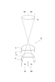
- the configuration of the light-shielding pixel 23 will be described with reference to the schematic diagram of FIG.
- the light-shielding pixel 23 includes a PD 30, a light-shielding portion 31 arranged in front of the PD 30 (subject side), an inner lens 32 arranged in front of the light-shielding portion 31, and a color filter arranged in front of the inner lens 32. It includes a cyan) 33 and an on-chip microlens 34 arranged in front of the color filter 33.
- the light-shielding pixel 23 may not be provided with the inner lens 32 or the color filter 33.
- the PD 30 is a light receiving element on which a part of the light that has passed through the exit pupil EP is incident, but the light blocking portion 31 arranged in front of the PD 30 makes it possible to receive light only in a part of the light receiving region of the PD 30. That is, the light-shielding portion 31 is formed so as to cover the left half region of the PD 30. A right opening 35R is formed in the light-shielding portion 31.
- the inner lens 32 and the on-chip microlens 34 are optical components provided for efficiently condensing the light that has passed through the exit pupil EP and incident on one pixel to the PD30.
- the color filter 33 is, for example, a filter having a spectral sensitivity of cyan (Cy).
- the PD30 is configured to receive only light passing through the left side region (left pupil region), which is the left half region of the exit pupil EP. That is, the light passing through the right side region (right pupil region), which is the right half region of the exit pupil EP, is shielded by the light shielding unit 31 and does not reach the PD 30. This realizes the pupil division function.
- the light-shielding pixel 23 configured to receive light passing through the left pupil region as shown in FIG. 15 is referred to as a light-shielding pixel 23R because it receives light in a region biased to the right on the light-receiving surface. That is, the light-shielding pixel 23R has a right opening 35R.
- the light-shielding pixel 23L having a configuration that is mirror-symmetrical with respect to the configuration shown in FIG. 15 is a light-shielding pixel 23 configured to receive light passing through the right pupil region, and this pixel is on the light-receiving surface. Light is received in the area biased to the left. As shown in FIG. 14, a left opening 35L is formed in the light-shielding portion 31 included in the light-shielding pixel 23L.
- the distance between the light-shielding pixels 23R and the light-shielding pixels 23L is, for example, the distance of two pixels, and they are arranged alternately.
- the signal output from the light-shielding pixel 23R and the signal output from the light-shielding pixel 23L are treated as a pair of phase difference signals by the camera signal processing unit 8 (or the camera control unit 14). That is, the phase difference detection unit 8a of the camera signal processing unit 8 can calculate the defocus amount by using the phase difference between the signal output from the light-shielding pixel 23R and the signal output from the light-shielding pixel 23L.
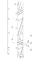
- FIG. 16 shows an example of a reading operation when such an image sensor 7 is assumed.
- the vertical period V2 will be mainly described. Exposure is sequentially started from the first horizontal line (HL1) to the last horizontal line (HLmax) at the timing indicated by the broken line EL1. Then, from the time point TM20, the first pixel row 22A is sequentially read as shown by the solid line RL3 (reading period TRm). This is for reading the values of the light-shielding pixels 23L and 23R, and is referred to as the third reading in distinction from the first reading and the second reading.
- reading is sequentially performed from the time point TM21 from the first horizontal line (HL1) to the last horizontal line (HLmax) as shown by the solid line RL1 parallel to the broken line EL1.
- This is the first read (see FIG. 10A). Since the first read is performed on all horizontal lines, both the first pixel row 22A including the light-shielding pixel 23 and the second pixel row 22B are read. Although each pixel value obtained by the first reading is used for image generation, the light-shielding pixel 23 is treated as an invalid pixel, and for example, one pixel value of the light-shielding pixel 23 is formed by interpolation processing.
- the exposure for the first reading of the next vertical period V3 shown as the broken line EL1 is started.
- the exposure of the broken line EL1 also serves as the exposure to the light-shielding pixel 23 for the third readout.
- the first read that reads (L + R) from all the PD division pixels 21 to be image-generated, and L for some pixels after thinning out.
- the second read for reading and (L + R) reading and the third reading for the light-shielding pixel 23 are performed in a time-division manner. Further, an exposure period for the first reading and the third reading (broken line EL1) and an exposure period for the second reading (broken line EL2) are separately provided. Also in this case, in the first reading indicated by the solid line RL1, since the reading is not performed twice in some horizontal lines, it is possible to eliminate the occurrence of unnatural edges in the image. Then, it is possible to perform phase difference detection based on the second read and the third read, and perform AF control.
- FIG. 16 The reading operation as shown in FIG. 16 is executed based on the control of the camera control unit 14.
- FIG. 17 shows a flowchart of the reading operation based on the control of the camera control unit 14.
- FIG. 18 shows the AF process associated with the reading operation. The description will be made assuming the imaging operation in the continuous shooting mode.
- step S151 of FIG. 17 the camera control unit 14 monitors the full press of the shutter button 6S. When the full push is not performed, other processing (not shown) is performed.
- step S151 When the full press of the shutter button 6S is detected in the continuous shooting mode, the camera control unit 14 proceeds from step S151 to step S152 to start the third reading.
- reading is sequentially started for the first pixel row 22A.
- the third read is started from the time point TM20 in FIG. 16 as the timing starting from the vertical synchronization signal that defines the vertical period.
- the value read from each light-shielding pixel 23 in this third read is used for phase difference detection in the camera signal processing unit 8.
- step S153 the camera control unit 14 starts the first reading from the time point TM21 in FIG.
- reading is sequentially started from the first horizontal line HL1.
- the (L + R) value read from each PD division pixel 21 in this first reading is processed as a pixel value for generating an image in the camera signal processing unit 8, and one still image data in continuous shooting is generated. ..
- step S154 the camera control unit 14 starts the exposure for the second reading from the time point TM22.
- exposure is sequentially started only for the horizontal line to be read second.
- step S155 the camera control unit 14 starts the second reading from the time point TM23.
- the second reading is sequentially performed only for the horizontal line to be the target of the second reading.
- the L value is read for each PD divided pixel 21 at the first time, and the (L + R) value is read at the second time.
- the L value may be read at the first time, and the R value may be read at the second time (or vice versa).
- step S156 the camera control unit 14 starts the exposure for the first reading and the third reading in the next vertical period.
- exposure is sequentially started for all the pixels (horizontal lines) to be image-generated.
- the camera control unit 14 returns to step S151, and if the shutter button 6S is fully pressed, the same process is continued.
- the camera control unit 14 exits the process shown in FIG. Even if the shutter button 6S is fully pressed, the process is exited even when the maximum number of continuous shots is exceeded.
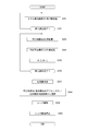
- AF control is performed as shown in FIG. 18 in response to the third reading in step S152 and the second reading in step S155.
- the camera signal processing unit 8 performs the processing of step S251 corresponding to each light-shielding pixel 23. That is, the L value and R value of the light-shielding pixel 23 are stored. This is a value read from a pair of light-shielding pixels 23L and 23R.
- the camera signal processing unit 8 When the third read is completed and the L values and R values of all the target light-shielding pixels 23L and 23R are stored, the camera signal processing unit 8 subsequently performs steps S253, S254, and S255 during the second read. The processing is performed corresponding to each PD divided pixel 21.
- the first L value as the second read is stored in step S253, the second (L + R) value as the second read is stored in step S254, and the second read (L + R) value is stored in step S255.
- step S258 the camera signal processing unit 8 performs phase difference detection and defocus amount calculation by the function of the phase difference detection unit 8a.
- the phase difference detection can be performed from the output of the light-shielding pixel 23 or from the output of the PD division pixel 21.
- the amount of defocus based on each of these phase difference detections is transmitted from the camera signal processing unit 8 to the camera control unit 14.
- step S258 the camera control unit 14 currently determines which one has the higher reliability, and selects the defocus amount based on either the light-shielding pixel 23 or the PD division pixel 21 accordingly. Then, the camera control unit 14 instructs the lens barrel control unit 18 in step S259 according to the defocus amount, and drives the focus lens included in the optical system 16. Then, in step S260, the lens drive is stopped. As a result, the AF operation is executed.
- the light-shielding pixel 23 and the PD-divided pixel 21 have the following differences.
- the light-shielding pixel 23 is a pixel used only for phase difference detection.
- the PD division pixel 21 can be used as a normal pixel (pixel for image generation) while being used for phase difference detection. Therefore, the light-shielding pixels 23 are arranged discretely, and the number of pixels cannot be increased so much. As a result, the PD split pixel 21 is superior to the light-shielding pixel 23 in terms of low illuminance performance and large F-number performance.
- the light-shielding pixel 23 is superior to the PD-divided pixel 21 in that it has a degree of freedom in pupil correction design and has good off-axis performance. Considering this, it is considered that the advantage of the PD split pixel 21 can be utilized in a low illuminance environment and the advantage of the light-shielding pixel 23 can be utilized in a high illuminance environment. Therefore, in step S258, it is conceivable to determine the reliability based on the illuminance environment. Specifically, one of the phase difference signals is selected according to the exposure amount.
- the calculation of the exposure amount will be described with reference to FIG. From the image sensor 7, a normal pixel output for generating a normal image signal and a phase difference pixel output as a phase difference signal for AF control are output.
- the normal pixel output referred to here is the (L + R) value from the PD divided pixel 21 by the first reading.
- the normal pixel output and the phase difference pixel output are input to the output level detection circuit provided in the camera signal processing unit 8, respectively.
- the output level detection circuit the output average value in the exposure calculation target area on the pixel is calculated based on the input normal pixel output and the phase difference pixel output, and each output average value is output from the camera signal processing unit 8. Is input to the camera control unit 14.
- the camera control unit 14 calculates the exposure amount according to the detection result output from the camera signal processing unit 8 and determines the shutter speed (or a parameter capable of adjusting the exposure amount such as F value and gain). The camera control unit 14 performs a process of setting the determined shutter speed in the image sensor 7.
- the exposure amount calculation performed by the camera control unit 14 may be performed based only on the normal pixel output, or may be performed based only on the phase difference pixel output. Further, it may be performed based on both the normal pixel output and the phase difference pixel output. In any case, the illuminance environment can be determined by the exposure amount calculation, and based on this, the phase difference detection result by the light-shielding pixel 23 is used or the phase difference detection result by the PD division pixel 21 is selected for AF control. be able to.
- Reading operation of the fourth embodiment> The reading operation as the fourth embodiment is shown in FIG. At the time point TM30 during the first reading indicated by the solid line RL1 in the vertical period V1, the exposure for the second reading shown as the broken line EL2 is started.
- the third read for the light-shielding pixel 23 is started at the timing indicated by the solid line RL3 from the time point TM31.
- the light-shielding pixels 23 are sequentially read out for each first pixel row 22A. From the time point TM32, a second read is performed as shown by the solid line RL2. Further, after the start of the second reading, the exposure is sequentially started from the first horizontal line (HL1) to the last horizontal line (HLmax) at the timing indicated by the broken line EL1.
- reading is sequentially performed from the time point TM33 from the first horizontal line (HL1) to the last horizontal line (HLmax).
- the exposure for the second read and the third read of the next vertical period V3 is started.
- the third read, the second read, and the first read are performed in this order in one vertical period corresponding to one frame. This also eliminates the occurrence of unnatural edges in the image obtained by the first reading indicated by the solid line RL1. Then, it is possible to perform phase difference detection based on the third read or the second read and perform AF control.
- FIG. 21 shows a reading operation as a fifth embodiment. This is an example in which the first read and the third read are performed at the same time. At the time point TM40 during the first read (and third read) indicated by the solid line RL1 (RL3) in the vertical period V1, the exposure for the second read indicated by the broken line EL2 is started.
- a second read is performed as shown by the solid line RL2. Further, after the start of the second reading, the exposure is sequentially started from the first horizontal line (HL1) to the last horizontal line (HLmax) at the timing indicated by the broken line EL1.
- the second read, the first read, and the third read are performed in this order in one vertical period corresponding to one frame. This also eliminates the occurrence of unnatural edges in the image obtained by the first reading indicated by the solid line RL1. Since the third read is performed in the process of the first read and the second read does not occur, there is no problem even if the first read and the third read are performed at the same time. Then, it is possible to perform phase difference detection based on the third read or the second read and perform AF control.
- the image pickup device 1 of the embodiment includes an image pickup element 7 having a PD division pixel 21 and a camera control unit 14, and the camera control unit 14 reads out a rolling shutter from the image pickup element 7.
- the first reading and the second reading are performed in time division, and the exposure period for the first reading and the exposure period for the second reading are separate. Control to be provided.
- the first read reads the (L + R) value which is the sum of the left PD40L (first pixel) and the right PD40R (second pixel) constituting the PD division pixel 21 for all the pixels to be image-generated.
- the second read is a read that can obtain the value of the left PD40L (first pixel) and the value of the right PD40R (second pixel) for some of the pixels to be image-generated.
- This makes it possible to prevent the influence of the left and right uncountable reading for phase difference detection when reading all the pixels to be image-generated. That is, in reading all the pixels to be image-generated, it is possible to avoid the operation of reading one horizontal line twice. This makes it possible to prevent an image in which the edge of a moving subject is displaced when reading the rolling shutter.
- the "all pixels targeted for image generation" targeted by the first readout do not mean all the pixels of the image pickup device 7. For example, if a dummy pixel is provided, it will be excluded.
- all effective pixels When reading out by thinning out the pixels among all the effective pixels as the reading for forming an image at the time of imaging, it means all the pixels after thinning out to be read out. For example, when a low-resolution mode is selected for a still image, or when a moving image is captured or a still image is continuously shot, the pixels forming one frame of the image may be thinned out. In those cases, "all pixels to be image-generated" refers to all pixels read out after decimation.
- a process of generating an image based on the added value obtained in the first read is performed, and the value of the left PD40L and the value of the right PD40R obtained in the second read are used.
- Phase difference detection processing was performed. Since the PD division pixel 21 is an effective pixel for image generation and a pixel for calculating the defocus amount by phase difference detection, it is usually assumed that reading is performed once, but in that case, one horizontal For each line, the left PD40L is read and the left PD40L and the right PD40R are read twice. Will be visible.
- the first reading and the second reading are performed in a time division manner, it is possible to prevent the first reading related to the image generation from causing the second reading of one horizontal line. As a result, it is possible to prevent unnatural edges from appearing in the image, and it is possible to improve the image quality.
- the exposure period is also set separately for the first read and the second read, but this does not use the (L + R) value due to the first read, but uses the (L + R) value and the L value due to the exposure before the second read. Means to do so. That is, the values of the left PD40L and the right PD40 can be obtained as the values of the same exposure opportunity. As a result, the amount of defocus can be obtained correctly, and accurate phase difference information can be obtained even if the reading is performed in a time division manner, and AF performance can be maintained, for example.
- the second reading is executed after the first reading is completed. That is, first, the first read is performed for image generation, and then the second read is performed for focus control in the subsequent frame.
- the order of the first read and the second read is not limited, but it is advantageous to perform the first read first in that, for example, an image pickup with a small time lag from the release operation can be realized.
- the first reading is executed after the second reading is completed. For example, first, a second read is performed for focus control in a subsequent frame, and then a second read is performed for image generation.
- a second read is performed for focus control in a subsequent frame
- a second read is performed for image generation.
- the exposure for the second reading is started before the first reading is completed. Even during the first reading, the line for which the reading has been completed can be exposed, so the exposure for the second reading is started. As a result, the period required for the operation of the first reading, the exposure for the second reading, and the second reading can be shortened. In other words, it is advantageous to shorten one vertical period during continuous shooting. Especially in the case of continuous shooting, it is desirable to shorten the time of one frame (one vertical period) as much as possible, which is preferable.
- the exposure for the second reading may be started after the first reading is completed.
- the second read is completed during the exposure for the first read. That is, the second read is performed in parallel with the exposure for the first read, and ends during the exposure period for the first read.
- the period required for the second read, the exposure for the first read, and the first read can be shortened.
- the first reading can be started when the second reading is completed. This is also advantageous for shortening one vertical period during continuous shooting.
- the exposure for the first reading may be started after the second reading is completed.
- the value of the left PD40L is read and the added value of the left PD40L and the right PD40R is read.
- the value of the left PD40L and the value of the right PD40R for calculating the defocus amount are obtained by reading the left PD40L and reading the left PD40L and the right PD40R twice for each horizontal line. Since the value obtained by the second reading is not used for image generation, even if such reading is performed twice, the image is not affected.
- the reading of the value of the right PD40R and the reading of the added value of the left PD40L and the right PD40R may be performed. Further, in the second read, for example, the left PD40L may be read and the right PD40R may be read twice, or the left PD40L and the right PD40R may be read independently at the same time.
- the image sensor 7 has a light-shielding portion that shields one of the pair of light fluxes that have passed through a pair of partial regions that are biased in opposite directions in a predetermined direction in the exit pupil and the other. It is assumed that it has a light-shielding pixel 23 having a pupil division function by providing a light-receiving element that receives the light flux of It is assumed that the phase difference detection process is performed using the values of the light-shielding pixels 23 obtained in 1.
- phase difference detection based on the PD divided pixel 21 and phase difference detection based on the light-shielded pixel 23 can be performed, for example, selectively depending on the situation. Can be used for.
- the third read is performed before the second read as the read corresponding to one frame of the image.
- the second read is performed before the third read as the read corresponding to one frame of the image.
- AF control is performed based on the third read. It can be executed and the responsiveness can be improved.
- AF control can be executed based on the second reading in a situation where the reliability of the defocus amount based on the PD divided pixel is high, and the responsiveness can be improved.
- which one may be read first may be switched according to the situation such as brightness.
- the fifth embodiment is an example in which the third read is performed together with the first read. As a result, it is not necessary to execute the third read as a period different from the first read, which is advantageous in shortening one vertical period.
- the focus control is performed using the result of the phase difference detection processing based on the second read and the result of the phase difference detection process based on the third read, whichever has the higher reliability. (See FIG. 18). This enables AF control that obtains the advantages of the PD split pixel and the light-shielding pixel, and can improve the reliability of AF.
- the thinning rate for setting some pixels to be read in the second readout in the embodiment may be variably set. This enables highly accurate phase difference detection depending on the situation. For example, by changing the thinning rate according to the brightness, the number of pixels for performing the second reading can be reduced in a bright situation, and the second reading time can be shortened.
- the first reading and the second reading are performed in a time-division manner when the still image continuous shooting is performed.
- the effect that an unnatural edge is generated in an image by performing reading for image generation and reading for calculating the defocus amount together is easily noticeable in the case of continuous shooting. Therefore, in the case of continuous shooting imaging, it is particularly effective to perform the first reading and the second reading in a time division manner to avoid deterioration of the image.
- the program of the embodiment is a program for causing, for example, a CPU, a DSP, or a device including these to execute each of the processes shown in FIGS. 11, 12, 17, and 18. That is, the program of the embodiment corresponds to one frame of the image when the arithmetic processing device in the image pickup device 1 provided with the image pickup element 7 including the PD division pixel 21 performs the rolling shutter reading from the image pickup element 7. As the reading to be performed, the first reading to read the added value of the first pixel and the second pixel constituting the PD divided pixel 21 for all the pixels to be image-generated, and a part of the pixels to be image-generated.
- the value of the first pixel and the second read from which the value of the second pixel can be obtained are performed in a time-divided manner, and the exposure period for the first read and the exposure for the second read are performed. It is a program that executes a process that allows a period to be set separately. With such a program, the above-mentioned image pickup apparatus 1 can be realized.
- a program that realizes such an image pickup device 1 can be recorded in advance in an HDD as a recording medium built in a device such as the image pickup device 1, a ROM in a microcomputer having a CPU, or the like.
- flexible discs CD-ROMs (Compact Disc Read Only Memory), MO (Magneto Optical) discs, DVDs (Digital Versatile Discs), Blu-ray discs (Blu-ray Disc (registered trademark)), magnetic discs, semiconductor memories, It can be temporarily or permanently stored (recorded) on a removable recording medium such as a memory card.
- Such removable recording media can be provided as so-called package software.
- a program from a removable recording medium on a personal computer or the like it can also be downloaded from a download site via a network such as a LAN (Local Area Network) or the Internet.
- LAN Local Area Network
- a program it is suitable for a wide range of provision of the image pickup apparatus 1 of the embodiment.
- a mobile terminal device such as a smart phone or tablet equipped with a camera function, a mobile phone, a personal computer, a game device, a video device, a PDA (Personal Digital Assistant), etc.
- these devices are disclosed.
- This technology can also adopt the following configurations.
- the first read, which reads out the image, and the second read, which can obtain the value of the first pixel and the value of the second pixel for some of the pixels to be image-generated, are performed in a time-divided manner.
- An image pickup device comprising a control unit for controlling the exposure period for the first reading and the exposure period for the second reading separately.
- a process of generating an image based on the added value obtained in the first readout is performed.
- the image pickup apparatus wherein the phase difference detection process is performed using the value of the first pixel and the value of the second pixel obtained by the second readout.
- the control unit executes the second reading after the first reading is completed as the reading corresponding to one frame of the image.
- the control unit executes the first reading after the second reading is completed as the reading corresponding to one frame of the image.
- the image pickup apparatus starts the exposure for the second reading before the first reading is completed.
- the image pickup apparatus is A light-shielding pixel having a pupil division function by providing a light-shielding portion that blocks one of a pair of light fluxes that have passed through a pair of partial regions that are biased in opposite directions in a predetermined direction in an exit pupil and a light-receiving element that receives the other light flux.
- the control unit controls so that the third read to read the light-shielding pixel is performed.
- the image pickup apparatus according to any one of (1) to (7) above, wherein the phase difference detection process is performed using the values of the light-shielding pixels obtained by the third readout.
- the image pickup apparatus according to (8) above, wherein the third read is performed before the second read as the read corresponding to one frame of the image.
- the image pickup apparatus according to (8) above, wherein the second read is performed before the third read as the read corresponding to one frame of the image.
- (11) The image pickup apparatus according to any one of (8) to (10) above, wherein the third read is performed collectively with the first read.
- Focus control is performed using the result of the phase difference detection processing based on the second read and the result of the phase difference detection process based on the third read, whichever has the higher reliability.
- the imaging device according to any one.
- the image pickup apparatus according to any one of (1) to (12) above, wherein the thinning rate for setting some pixels to be read in the second read is variably set.
- the image pickup apparatus according to any one of (1) to (11) above, wherein the first read and the second read are performed in a time-division manner when the still image continuous shooting image is performed.
- As an image pickup method of an image pickup device equipped with an image pickup element equipped with a photodiode divided pixel as an image pickup method.
- the first read, which reads out the image, and the second read, which can obtain the value of the first pixel and the value of the second pixel for some of the pixels to be image-generated, are performed in a time-divided manner.
- An image pickup method in which the exposure period for the first reading and the exposure period for the second reading are separately provided.
- Image pickup device 2 Camera housing 3 Lens lens barrel 6S Shutter button 7 Image pickup element 8
- Camera control unit 21 PD division pixel 22A First pixel row 22B Second pixel row 23, 23R, 23L Light-shielding pixel 40L Left PD 40R right PD
Landscapes
- Engineering & Computer Science (AREA)
- Multimedia (AREA)
- Signal Processing (AREA)
- Physics & Mathematics (AREA)
- General Physics & Mathematics (AREA)
- Optics & Photonics (AREA)
- Studio Devices (AREA)
- Focusing (AREA)
Priority Applications (2)
| Application Number | Priority Date | Filing Date | Title |
|---|---|---|---|
| JP2022527553A JP7655317B2 (ja) | 2020-05-25 | 2021-04-06 | 撮像装置、撮像方法 |
| US17/999,058 US12238434B2 (en) | 2020-05-25 | 2021-04-06 | Imaging device and imaging method for autofocus control |
Applications Claiming Priority (2)
| Application Number | Priority Date | Filing Date | Title |
|---|---|---|---|
| JP2020090343 | 2020-05-25 | ||
| JP2020-090343 | 2020-05-25 |
Publications (1)
| Publication Number | Publication Date |
|---|---|
| WO2021241015A1 true WO2021241015A1 (ja) | 2021-12-02 |
Family
ID=78744297
Family Applications (1)
| Application Number | Title | Priority Date | Filing Date |
|---|---|---|---|
| PCT/JP2021/014669 Ceased WO2021241015A1 (ja) | 2020-05-25 | 2021-04-06 | 撮像装置、撮像方法 |
Country Status (3)
| Country | Link |
|---|---|
| US (1) | US12238434B2 (https=) |
| JP (1) | JP7655317B2 (https=) |
| WO (1) | WO2021241015A1 (https=) |
Citations (2)
| Publication number | Priority date | Publication date | Assignee | Title |
|---|---|---|---|---|
| WO2019035374A1 (ja) * | 2017-08-18 | 2019-02-21 | ソニー株式会社 | 撮像素子および撮像装置 |
| JP2019050486A (ja) * | 2017-09-08 | 2019-03-28 | オリンパス株式会社 | 撮像装置、撮像装置の制御方法 |
Family Cites Families (6)
| Publication number | Priority date | Publication date | Assignee | Title |
|---|---|---|---|---|
| US9257468B2 (en) * | 2012-11-21 | 2016-02-09 | Olympus Corporation | Solid-state imaging device, imaging device, and signal reading medium that accumulates an amplified signal without digitization |
| CN106464781B (zh) * | 2014-05-08 | 2020-11-03 | 索尼公司 | 信息处理装置和信息处理方法 |
| JP2018081224A (ja) | 2016-11-17 | 2018-05-24 | キヤノン株式会社 | 撮像装置およびその制御方法 |
| JP6777230B2 (ja) | 2017-06-29 | 2020-10-28 | 株式会社島津製作所 | 放射線計測器および放射線撮影装置 |
| JP2020012879A (ja) | 2018-07-13 | 2020-01-23 | オリンパス株式会社 | 撮像素子、焦点検出装置、撮像方法、および焦点検出方法 |
| JP7366635B2 (ja) * | 2019-08-07 | 2023-10-23 | キヤノン株式会社 | 撮像装置、コンピュータプログラム及び記憶媒体 |
-
2021
- 2021-04-06 US US17/999,058 patent/US12238434B2/en active Active
- 2021-04-06 WO PCT/JP2021/014669 patent/WO2021241015A1/ja not_active Ceased
- 2021-04-06 JP JP2022527553A patent/JP7655317B2/ja active Active
Patent Citations (2)
| Publication number | Priority date | Publication date | Assignee | Title |
|---|---|---|---|---|
| WO2019035374A1 (ja) * | 2017-08-18 | 2019-02-21 | ソニー株式会社 | 撮像素子および撮像装置 |
| JP2019050486A (ja) * | 2017-09-08 | 2019-03-28 | オリンパス株式会社 | 撮像装置、撮像装置の制御方法 |
Also Published As
| Publication number | Publication date |
|---|---|
| US12238434B2 (en) | 2025-02-25 |
| US20230199342A1 (en) | 2023-06-22 |
| JP7655317B2 (ja) | 2025-04-02 |
| JPWO2021241015A1 (https=) | 2021-12-02 |
Similar Documents
| Publication | Publication Date | Title |
|---|---|---|
| EP2181349B1 (en) | Image sensing apparatus | |
| JP2010506493A (ja) | 信号センサからの多重ビデオ信号の供給 | |
| JP6584059B2 (ja) | 撮像装置及びその制御方法、プログラム、記憶媒体 | |
| CN103125112A (zh) | 成像设备以及成像方法 | |
| JP7709565B2 (ja) | 撮像装置、撮像装置の駆動方法、及びプログラム | |
| JP2019106634A (ja) | 撮像素子及び撮像装置 | |
| JP2017194558A (ja) | 撮像装置および撮像方法 | |
| JP6604216B2 (ja) | 撮像装置 | |
| JP4053858B2 (ja) | 固体撮像装置の信号読出し方法 | |
| US10999492B2 (en) | Focus adjustment device and focus adjustment method | |
| JP7655316B2 (ja) | 撮像装置、撮像方法 | |
| JP7027133B2 (ja) | 焦点検出装置及び焦点検出方法 | |
| JP7655317B2 (ja) | 撮像装置、撮像方法 | |
| WO2020137217A1 (ja) | 撮像素子、撮像装置、画像データ処理方法、及びプログラム | |
| JP2009267593A (ja) | 撮像装置、欠陥画素検出方法および欠陥画素検出プログラム | |
| JP2023121622A (ja) | 検出装置および検出方法 | |
| JP7129864B2 (ja) | 撮像装置及びその制御方法 | |
| JP5127510B2 (ja) | 撮像装置、及び撮像装置の制御方法 | |
| JP4991602B2 (ja) | 撮像装置 | |
| JP7679771B2 (ja) | 撮像装置、デフォーカス量算出方法 | |
| JP5836673B2 (ja) | 撮像装置、撮像装置の制御方法、及びコンピュータプログラム | |
| JP2006148591A (ja) | 固体撮像装置および固体撮像素子駆動方法 | |
| JP6929752B2 (ja) | 焦点検出装置及び焦点検出方法 | |
| JP6604215B2 (ja) | 撮像装置 | |
| JP2007228152A (ja) | 固体撮像装置および撮像方法 |
Legal Events
| Date | Code | Title | Description |
|---|---|---|---|
| 121 | Ep: the epo has been informed by wipo that ep was designated in this application |
Ref document number: 21813937 Country of ref document: EP Kind code of ref document: A1 |
|
| ENP | Entry into the national phase |
Ref document number: 2022527553 Country of ref document: JP Kind code of ref document: A |
|
| NENP | Non-entry into the national phase |
Ref country code: DE |
|
| 122 | Ep: pct application non-entry in european phase |
Ref document number: 21813937 Country of ref document: EP Kind code of ref document: A1 |
|
| WWG | Wipo information: grant in national office |
Ref document number: 17999058 Country of ref document: US |