WO2021240718A1 - 熱処理装置及び熱処理方法 - Google Patents
熱処理装置及び熱処理方法 Download PDFInfo
- Publication number
- WO2021240718A1 WO2021240718A1 PCT/JP2020/021093 JP2020021093W WO2021240718A1 WO 2021240718 A1 WO2021240718 A1 WO 2021240718A1 JP 2020021093 W JP2020021093 W JP 2020021093W WO 2021240718 A1 WO2021240718 A1 WO 2021240718A1
- Authority
- WO
- WIPO (PCT)
- Prior art keywords
- oil
- treated
- drying chamber
- heat
- processed
- Prior art date
- Legal status (The legal status is an assumption and is not a legal conclusion. Google has not performed a legal analysis and makes no representation as to the accuracy of the status listed.)
- Ceased
Links
Images







Classifications
-
- F—MECHANICAL ENGINEERING; LIGHTING; HEATING; WEAPONS; BLASTING
- F26—DRYING
- F26B—DRYING SOLID MATERIALS OR OBJECTS BY REMOVING LIQUID THEREFROM
- F26B5/00—Drying solid materials or objects by processes not involving the application of heat
- F26B5/04—Drying solid materials or objects by processes not involving the application of heat by evaporation or sublimation of moisture under reduced pressure, e.g. in a vacuum
- F26B5/06—Drying solid materials or objects by processes not involving the application of heat by evaporation or sublimation of moisture under reduced pressure, e.g. in a vacuum the process involving freezing
-
- C—CHEMISTRY; METALLURGY
- C21—METALLURGY OF IRON
- C21D—MODIFYING THE PHYSICAL STRUCTURE OF FERROUS METALS; GENERAL DEVICES FOR HEAT TREATMENT OF FERROUS OR NON-FERROUS METALS OR ALLOYS; MAKING METAL MALLEABLE, e.g. BY DECARBURISATION OR TEMPERING
- C21D1/00—General methods or devices for heat treatment, e.g. annealing, hardening, quenching or tempering
- C21D1/18—Hardening; Quenching with or without subsequent tempering
-
- C—CHEMISTRY; METALLURGY
- C21—METALLURGY OF IRON
- C21D—MODIFYING THE PHYSICAL STRUCTURE OF FERROUS METALS; GENERAL DEVICES FOR HEAT TREATMENT OF FERROUS OR NON-FERROUS METALS OR ALLOYS; MAKING METAL MALLEABLE, e.g. BY DECARBURISATION OR TEMPERING
- C21D1/00—General methods or devices for heat treatment, e.g. annealing, hardening, quenching or tempering
- C21D1/56—General methods or devices for heat treatment, e.g. annealing, hardening, quenching or tempering characterised by the quenching agents
- C21D1/58—Oils
Definitions
- the present invention relates to a heat treatment technique.
- a heat treatment apparatus that performs heat treatment such as quenching using heat treatment oil is known (for example, Patent Document 1).
- the heat treatment oil adheres to the object to be treated.
- the attached heat treatment oil may adversely affect the next process. Therefore, before proceeding to the next step, a removal step of removing the heat-treated oil remaining on the object to be treated is performed. This removing step is performed, for example, by cleaning the object to be processed with a vacuum cleaning device and drying it (for example, Patent Document 2).
- An object of the present invention is to provide a technique capable of removing heat-treated oil from an object to be treated without cleaning with a solvent.
- a drying chamber in which the object to be treated is housed after heat treatment with heat treatment oil, A decompression means for depressurizing the drying chamber and A control means for controlling the decompression means is provided.
- the control means controls the air pressure in the drying chamber so that the heat-treated oil adhering to the object to be treated is vaporized in the drying chamber.
- a device characterized by this is provided.
- the schematic diagram of the heat treatment apparatus which concerns on one Embodiment of this invention.
- the figure which shows the example of the processing operation of the object to be processed by the heat treatment apparatus of FIG. The figure which shows the example of the processing operation of the object to be processed by the heat treatment apparatus of FIG.
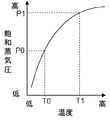
- the figure which shows the example of the processing operation of the object to be processed by the heat treatment apparatus of FIG. A flowchart showing an example of the drying process performed by the control unit. Is a diagram showing the relationship between the temperature of the heat-treated oil and the saturated vapor pressure.
- the schematic diagram of the heat treatment apparatus which concerns on another embodiment.
- the schematic diagram of the heat treatment apparatus which concerns on still another Embodiment.
- the figure which shows the example of the processing operation of the object to be processed by the heat treatment apparatus of FIG. The figure which shows the example of the processing operation of the object to be processed by the heat treatment apparatus of FIG.
- the figure which shows the temperature change of the object to be processed in the heat treatment apparatus of FIG. The figure which shows the relationship between the temperature of a heat-treated oil and the saturated vapor pressure.
- the schematic diagram of the heat treatment apparatus which concerns on still another Embodiment.
- FIG. 1 is a schematic view of a heat treatment apparatus 1 according to an embodiment of the present invention.
- the heat treatment apparatus 1 is an apparatus that continuously quenches and dries an object to be processed such as a metal material.
- the heat treatment device 1 includes a heating device 10, a cooling device 20, and a drying device 30 that are continuously arranged in the D direction, which is the transport direction of the object to be processed.
- the heating device 10 includes a processing chamber 11 that can be maintained airtight.
- the treatment chamber 11 is a heating chamber for heating the object to be treated.
- a carry-in inlet 2 for carrying an object to be processed is formed at one end of the processing chamber 11 in the D direction, and a communication port 3 communicating with the processing chamber 21 of the cooling device 20 is formed at the other end.
- the carry-in inlet 2 is opened and closed by the opening / closing door 2a that moves by driving the actuator 2b, and the communication port 3 is opened / closed by the opening / closing door 3a that moves by driving the actuator 3b.
- the actuators 2b and 3b are, for example, fluid cylinders that move up and down the opening / closing doors 2a and 3a.
- a transport unit 12 is provided in the processing chamber 11.
- the transport unit 12 is a roller conveyor provided with a plurality of rollers 12a, and moves the object to be processed horizontally in the D direction.
- a heating unit 13 is also provided in the processing chamber 11.
- the heating unit 13 includes a plurality of heat generating elements 13a, and heats the object to be processed carried into the processing chamber 11 in an airtight state of the processing chamber 11.
- the cooling device 20 includes a processing chamber 21 that can maintain airtightness.
- the treatment chamber 21 is a heat treatment chamber for quenching the object to be treated.
- the object to be heated in the processing chamber 11 is carried into the processing chamber 21 through the communication port 3 at one end in the D direction of the processing chamber 21.
- the communication port 3 is formed in a partition wall that separates the processing chamber 11 and the processing chamber 21, and the processing chamber 11 and the processing chamber 21 communicate with each other via the opening / closing door 3a.
- a communication port 4 communicating with the drying chamber 31 of the drying device 30 is formed at the other end of the processing chamber 21 in the D direction.
- the communication port 4 is opened and closed by the opening / closing door 4a that moves by driving the actuator 4b. When the opening / closing doors 3a and 4a are closed, the processing chamber 21 is in an airtight state.
- the actuator 4b is, for example, a fluid cylinder that moves up and down the opening / closing door 4a.
- the processing chamber 21 includes an upper space 21a and a lower space 21b.
- the upper space 21a is a transport chamber provided with the transport unit 22.
- the transport unit 22 is a roller conveyor provided with a plurality of rollers 22a, and moves the object to be processed horizontally in the D direction.
- An oil tank 23 for storing the heat-treated oil 23a is provided in the lower space 21b.
- the heat-treated oil 23a is a cooling oil (quenched oil), and the object to be treated is cooled by immersing the object to be treated in the heat-treated oil 23a.
- the heat-treated oil 23a in the oil tank 23 is heated by the heater 24 based on the detection result of the oil temperature by the oil temperature sensor 25, and is maintained at a predetermined oil temperature.
- the processing chamber 21 is provided with a moving mechanism 26 for moving the object to be processed.
- the moving mechanism 26 includes an elevating table 26a for supporting the object to be processed and an actuator 26b.
- the elevating table 26a is driven by the actuator 26b to move up and down between the ascending position shown by the solid line and the descent position shown by the broken line.
- the actuator 26b is, for example, a fluid cylinder.
- a roller 22a is provided on the elevating table 26a. When the elevating table 26 is in the ascending position, the elevating table 26 functions as a part of the conveying unit 22 that conveys the object to be processed in the D direction.
- the elevating table 26 can immerse the object to be treated in the oil tank 23 by mounting the object to be processed and descending to the descending position, and by ascending from the descending position to the ascending position, the object to be processed can be raised. It can be pulled up from the oil tank 23.
- the drying device 30 includes a drying chamber 31 that can maintain airtightness.
- the drying chamber 31 accommodates the object to be treated after the heat treatment with the heat treatment oil 23a.
- the object to be treated to which the heat treatment oil 23a is attached to the surface is dried in the drying chamber 31.
- the object to be cooled in the processing chamber 21 is carried into the drying chamber 31 through the communication port 4 at one end in the D direction of the drying chamber 31.
- the communication port 4 is formed in a partition wall that separates the processing chamber 21 and the drying chamber 31, and the processing chamber 21 and the drying chamber 31 communicate with each other via the opening / closing door 4a.
- a carry-out port 5 is formed at the other end of the drying chamber 31 in the D direction.
- the carry-out port 5 is opened and closed by the opening / closing door 5a that is moved by the drive of the actuator 5b.
- the actuator 5b is, for example, a fluid cylinder that moves up and down the opening / closing door 5a.
- the drying chamber 31 is provided with a transport unit 32.
- the transport unit 32 is a roller conveyor provided with a plurality of rollers 32a, and moves the object to be processed horizontally in the D direction.
- the drying device 33 includes a decompression unit 33 that depressurizes the drying chamber 31.
- the pressure reducing unit 33 of the present embodiment includes a vacuum pump 33a that communicates with the drying chamber 31 via a pipe, and a control valve 33b provided in the middle of the pipe between the drying chamber 31 and the vacuum pump 33a. By driving the vacuum pump 33a, the gas in the drying chamber 31 is discharged to the outside, and the drying chamber 31 can be depressurized.
- the control valve 33b is opened, the drying chamber 31 and the vacuum pump 33a are in a communicating state, and when the valve is closed, the drying chamber 31 is closed.
- the drying chamber 31 is provided with a sensor 34 that detects the air pressure in the drying chamber 31.
- a sensor 34 that detects the air pressure in the drying chamber 31.
- the drying chamber 31 can be maintained at the control target atmospheric pressure.
- evaporation of the heat-treated oil 23a adhering to the object to be treated is promoted, and the steam thereof is discharged to the outside of the drying chamber 31.
- the heat treatment oil 23a adhering to the object to be treated is removed, and the object to be treated is dried.
- a condenser 35 is provided between the vacuum pump 33a and the control valve 33b.
- the condenser 35 is provided with a pipe 35a through which cooling water having a temperature equal to or lower than the condensation point of the heat treatment oil 23a passes, and heat exchange is performed between the gas discharged from the drying chamber 31 and the cooling water. As a result, the steam of the heat-treated oil 23a discharged from the drying chamber 31 is liquefied.
- the liquefied heat-treated oil 23a is returned to the oil tank 23 via the recovery system 36.
- the recovery system 36 includes, for example, a pipe between the condenser 35 and the oil tank 23, a reservoir for the heat-treated oil 23a, a pump for delivering the heat-treated oil 23a in the reservoir to the oil tank 23, and the like. With such a configuration, it is possible to prevent the heat treatment oil 23a from reaching the vacuum pump 33a and deteriorating the vacuum pump 33a, and the heat treatment oil 23a can be reused.
- the heat treatment device 1 includes a control unit 40.
- the control unit 40 includes a processor typified by a CPU, a storage device such as a ROM and a RAM, an I / O interface for inputting / outputting signals between an external device (sensor or actuator) of the control unit 40 and the processor, and the like. ..
- a program executed by the processor is stored in the storage device, the processor executes this program, and the heat treatment device 1 operates by driving the actuator or the like based on the detection result of the sensor.
- FIGS. 2A to 2C are diagrams showing an example of the processing operation of the object W to be processed by the heat treatment apparatus 1.
- FIG. 2A shows a state in which the object W to be processed is carried into the processing chamber 11 through the carry-in inlet 2 and heat-treated. After that, the processing chamber 11 is made airtight and heated by the heat generated by the heating unit 13. As a result, the object W to be processed is heated to the quenching temperature.
- the opening / closing door 3a is opened, and the object W to be processed is conveyed from the processing chamber 11 to the processing chamber 21 through the communication port 3 by the transport units 12 and 22. After that, the processing chamber 21 is brought into an airtight state.
- FIG. 2B shows the processing of the object to be processed W in the processing chamber 21.
- the object W to be processed is conveyed on the elevating table 26a.
- the elevating table 26a descends to the descending position, and the object W to be processed is immersed in the heat treatment oil 23a. Quenching treatment is performed in which the object W to be treated is rapidly cooled with the heat treatment oil 23a.
- the object W to be treated is immersed until it reaches a predetermined temperature, and in the case of the present embodiment, the predetermined temperature is equal to the oil temperature T0 of the heat treatment oil 23a. Whether or not the object W to be processed has been cooled to a predetermined temperature T0 can be determined, for example, by the immersion time.
- the elevating table 26a is raised to the ascending position indicated by the broken line, and the object W to be processed is pulled up from the oil tank 23.
- the opening / closing door 4a is opened, and as shown in FIG. 2C, the object W to be processed is conveyed from the processing chamber 21 to the drying chamber 31 through the communication port 4 by the conveying units 22 and 32. NS. After that, the drying chamber 31 is brought into an airtight state. Subsequently, the drying chamber 31 is depressurized by the operation of the depressurizing unit 33, and the heat-treated oil 23a adhering to the object W to be processed is vaporized. Since the temperature of the object W to be processed is T0, the oil temperature of the heat-treated oil 23a remaining in the object W to be processed is also T0. As shown in FIG.
- the heat treatment oil 23a can be removed from the object W to be treated without cleaning with a solvent, so that the solvent cleaning of the object W to be processed, which has been conventionally required, becomes unnecessary. Therefore, since it is not necessary to install a cleaning device and a transport device associated therewith, it is possible to reduce the initial cost of the device, the maintenance cost, the installation space of various devices, and the like, and it is possible to construct an efficient production line. In addition, a cleaning solvent is not required, and resources can be protected.
- the opening / closing door 5a is opened, and the object W to be processed is carried out of the apparatus from the carry-out port 5. As a result, one cycle of processing is completed.
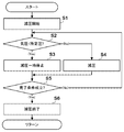
- FIG. 3A is a flowchart showing a control example related to drying of the object to be processed W in the drying apparatus 30, and is executed when the object to be processed W is conveyed to the drying chamber 31 and the drying chamber 31 becomes airtight. This is a processing example.
- the decompression unit 33 is driven to start depressurization of the drying chamber 31.
- the vacuum pump 33a is driven to open the control valve 33b.
- the vacuum pump 33a may be driven in advance and may be constantly driven.
- the detection result of the sensor 34 is acquired, and it is determined whether or not the air pressure in the drying chamber 31 is less than the predetermined pressure.
- the atmospheric pressure of the drying chamber 31 detected by the sensor 34 is the total atmospheric pressure of the partial pressure of the steam of the heat treatment oil 23a and other gases (for example, air) that may exist in the drying chamber 31. Therefore, the predetermined pressure as a comparison reference is set in advance by experiments or the like in consideration of the saturated vapor pressure P0 of the heat-treated oil 23a and the partial pressure of other gases, and the partial pressure of the steam of the heat-treated oil 23a is the saturated vapor pressure P0. It is a value corresponding to the atmospheric pressure of the drying chamber 31 when it is lower than. If the air pressure in the drying chamber 31 is less than the predetermined pressure, the process proceeds to S3, and if the pressure is equal to or higher than the predetermined pressure, the process proceeds to S4.
- the control valve 33b is closed to temporarily stop the depressurization of the drying chamber 31.
- the depressurization of the drying chamber 31 is continued.
- the completion condition for example, the elapsed time from the start of depressurization of S1 has reached a predetermined time.
- the elapsed time from the first determination that the atmospheric pressure in the drying chamber 31 is less than the predetermined atmospheric pressure in S2 has reached the predetermined time.
- the case where the atmospheric pressure in the drying chamber 31 (detection result of the sensor 34) is continuously below the threshold value for a predetermined time can be mentioned.
- the process proceeds to S6, and if not, the process returns to S2 and the same process is repeated.
- the partial pressure of the heat-treated oil 23a in the drying chamber 31 is maintained lower than the saturated vapor pressure P0 until the completion condition is satisfied.
- the control valve 33b is closed.
- the vacuum pump 33a may be stopped or may remain driven for the next process.
- the heat treatment oil 23a can be removed from the object W to be treated and dried.
- the pressure reducing unit 33 is provided with the vacuum pump 33a and the control valve 33b, but may be configured with only the vacuum pump 33a.
- the decompression / decompression stop of the drying chamber 31 is switched by driving / stopping the vacuum pump 33a.
- the pressure in the drying chamber 31 is controlled to be maintained at a predetermined pressure by the treatments of S2 to S5, but the pressure in the drying chamber 31 may be lower than the predetermined pressure, so that the pressure in S3 is reduced. The depressurization may be continued until the completion condition is satisfied without suspending.
- FIG. 4 is a schematic view of the heat treatment apparatus 1A according to the present embodiment. A configuration different from that of the heat treatment apparatus 1 of the first embodiment will be described.
- the heat treatment device 1A is provided with a cooling device 20A and a reheating device 20B between the heating device 10 and the drying device 30 in the D direction.
- the configurations of the cooling device 20A and the reheating device 20B are the same as those of the cooling device 20 of the first embodiment, but the cooling device 20A is used for quenching the object to be processed and the reheating device 0B is used for tempering the object to be processed. ..
- the cooling device 20A and the reheating device 20B communicate with each other through a communication port 6 formed in a partition wall that divides each of the processing chambers 21, and the opening / closing door 6a opens / closes the communication port 6 by driving the actuator 6b.
- the drying device 30 is used to remove the heat-treated oil 23a adhering to the object to be treated after tempering by the reheating device 20B.
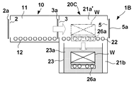
- FIG. 5 is a schematic view of the heat treatment apparatus 1C according to the present embodiment. A configuration different from that of the heat treatment apparatus 1 of the first embodiment will be described.
- the heat treatment device 1B includes a heating device 10 and a cooling device 20C continuously arranged in the D direction.
- the configuration of the heating device 10 is the same as that of the heating device 10 of the first embodiment.
- the cooling device 20C utilizes the upper space 21a of the processing chamber 21 of the cooling device 20 of the first embodiment as the drying chamber 21a'.
- the cooling device 20C will be described with appropriate comparison with the cooling device 20 and the drying device 30 of the first embodiment.
- the cooling device 20C includes a processing chamber 21 that can maintain airtightness.
- the treatment chamber 21 is a heat treatment chamber for quenching the object to be processed and also functions as a drying chamber for drying the object to be processed. Similar to the first embodiment, the object to be heated in the processing chamber 11 is carried into the processing chamber 21 through the communication port 3 at one end in the D direction of the processing chamber 21.
- the carry-out port 5 is formed at the other end of the processing chamber 21 in the D direction. The carry-out port 5 is opened and closed by the opening / closing door 5a that is moved by the drive of the actuator 5b. When the opening / closing doors 3a and 5a are closed, the processing chamber 21 is in an airtight state.
- the processing chamber 21 includes a drying chamber 21a'which is an upper space and a lower space 21b.
- the drying chamber 21a' is a transport chamber provided with the transport unit 22, and is a storage chamber for accommodating the object to be heat-treated with the heat-treated oil 23a.
- the object to be treated to which the heat treatment oil 23a is attached to the surface is dried.
- the lower space 21b is provided with an oil tank 23 for storing the heat-treated oil 23a, and is also provided with an oil temperature sensor 25 and a heater 24.
- the processing chamber 21 is provided with a moving mechanism 26 for moving the object to be processed, and the object to be processed is moved between the descending position and the ascending position.
- the cooling device 20C includes a decompression unit 33 for depressurizing the processing chamber 21 including the drying chamber 21a', and the decompression unit 33 has the same configuration as the decompression unit 33 of the first embodiment.
- the drying chamber 21a' is provided with a sensor 34 for detecting the air pressure in the drying chamber 21a'.
- a condenser 35 is provided between the vacuum pump 33a and the control valve 33b, and the condenser 35 is provided with a pipe 35a through which cooling water passes.
- the heat-treated oil 23a liquefied by the condenser 35 is returned to the oil tank 23 via the recovery system 36.
- FIGS. 6A to 6C are diagrams showing an example of the processing operation of the object W to be processed by the heat treatment apparatus 1C.
- FIG. 6A shows a state in which the object W to be processed is carried into the processing chamber 11 through the carry-in inlet 2 and heat-treated. After that, the processing chamber 11 is made airtight and heated by the heat generated by the heating unit 13. As a result, the object W to be processed is heated to the quenching temperature.
- the opening / closing door 3a is opened, and the object W to be processed is conveyed from the processing chamber 11 to the processing chamber 21 through the communication port 3 by the transport units 12 and 22. After that, the processing chamber 21 is brought into an airtight state.
- FIG. 6B shows the processing of the object to be processed W in the processing chamber 21.
- the object W to be processed is conveyed on the elevating table 26a.
- the elevating table 26a descends to the descending position, and the object W to be processed is immersed in the heat treatment oil 23a. Quenching treatment is performed in which the object W to be treated is rapidly cooled with the heat treatment oil 23a.
- the object W to be treated is immersed until it reaches a predetermined temperature, and in the case of the present embodiment, the predetermined temperature is a temperature T1 higher than the oil temperature T0 of the heat treatment oil 23a.
- Whether or not the object W to be processed has been cooled to a predetermined temperature T1 can be determined, for example, by the immersion time. After that, the elevating table 26a is raised to the ascending position indicated by the broken line, and the object W to be processed is pulled up from the oil tank 23.
- the object W to be processed is moved from the oil tank 23 to the drying chamber 21a'when the object W to be processed is cooled to a temperature T1 higher than the oil temperature T0 of the heat-treated oil 23a in the oil tank 23. ..
- the drying chamber 21a' is decompressed by the operation of the decompression unit 33, and the heat treatment oil 23a adhering to the object W to be processed is vaporized. Since the temperature of the object to be treated W is T1, the oil temperature of the heat-treated oil 23a remaining in the object to be processed W is also T1.
- the transition of the temperature change of the object W to be processed in the cooling device 20C will be described with reference to FIG. 7A.
- the times t0 to t1 indicate the stage where the elevating table 26a descends from the ascending position to the descending position, and indicate the stage where the object W to be processed is submerged in the oil tank 23.
- the object W to be treated has a quenching temperature T2 (> T1> T0) by heat treatment by the heating device 10.
- T1 the quenching temperature
- the times t2 to t3 indicate the stage in which the elevating table 26a rises from the descent position to the ascending position, and indicate the stage in which the object W to be processed is pulled up from the oil tank 23. Drying of the object W to be processed is started from time t3.
- the partial pressure of the heat-treated oil 23a in the drying chamber 21a' is kept lower than the saturated vapor pressure P1 and higher than the saturated vapor pressure P0.
- the heat-treated oil 23a adhering to the object W to be treated can be evaporated and removed, and the heat-treated oil 23a in the oil tank 23 can be prevented from evaporating while drying.
- the vacuum pump 33a avoids sucking a large amount of steam of the heat-treated oil 23a derived from the oil tank 23, and it is possible to selectively vaporize only the heat-treated oil 23a adhering to the object W to be processed.
- the opening / closing door 5a is opened, and the object W to be processed is carried out of the apparatus from the carry-out port 5. As a result, one cycle of processing is completed. According to this embodiment, since the object W to be processed can be dried in the cooling device 20C, the efficiency of the heat treatment line can be improved.
- the dried object W can be transferred to the air cooling process.
- the quenching method that combines rapid cooling and slow cooling in this way is known as so-called marquenching, but as described in the present embodiment, the drying method of the present embodiment can also be applied to marquenching.
- the example of drying control of the control unit 40 in this embodiment is the same as the flowchart illustrated in FIG. 3A.
- the predetermined pressure as a comparison reference may be present in the partial pressure of the steam of the heat treatment oil 23a and the drying chamber 21a'(for example, air). It is set in advance by an experiment or the like in consideration of the partial pressure.
- the saturated vapor pressures P1 and P0 are also taken into consideration, and the value corresponding to the atmospheric pressure of the drying chamber 21a'when the partial pressure of the steam of the heat treatment oil 23a is lower than the saturated vapor pressure P1 and higher than the saturated vapor pressure P0. It is said that.
- the air pressure in the drying chamber 21a' can be controlled so that the heat-treated oil 23a having a temperature T1 adhering to the object W is vaporized, while the heat-treated oil 23a in the oil tank 23 having an oil temperature T0 is not vaporized.
- FIG. 8 is a schematic view of the heat treatment apparatus 1D according to the present embodiment.
- the heat treatment device 1D includes a heating device 10A continuously arranged in the D direction, a cooling device 20D, a heating device 10B, and a cooling device 20E.
- the heating device 10A and the cooling device 20D have the same configuration as the heating device 10 and the cooling device 20C of the third embodiment, and the heating device 10B and the cooling device 20E also have the same configuration as the heating device 10 and the cooling device 20C of the third embodiment.
- the processing chamber 21 of the cooling device 20D and the processing chamber 11 of the heating device 10B communicate with each other at the communication port 7, and the communication port 7 is opened and closed by the opening / closing door 7a that is moved by the drive of the actuator 7b.
- the processing chamber 21 of the cooling device 20D is in an airtight state.
- the processing chamber 11 of the heating device 10B and the processing chamber 21 of the cooling device 20E communicate with each other at the communication port 8, and the communication port 8 is opened and closed by the opening / closing door 8a which is moved by the drive of the actuator 8b.
- the processing chamber 11 of the heating device 10B is in an airtight state.
- a carry-out port 5 is formed in the cooling device 20E. When the opening / closing doors 8a and 5a are closed, the processing chamber 21 of the cooling device 20E is in an airtight state.
- the object to be treated is sequentially subjected to heat treatment by the heating device 10A, quenching and drying by the cooling device 20D, heat treatment by the heating device 10B, and quenching and drying by the cooling device 20E.
- the control of each device is the same as that described in the third embodiment.
- heating and quenching of the object to be processed can be repeated, and for example, the metal material can be strengthened by so-called grain refinement. Then, when the object to be treated by the cooling device 20D is conveyed to the heating device 10B and the heat treatment is performed, the object to be treated has already been dried, so that the second heat treatment can be performed quickly.
- the heating devices 10 to 10B, the cooling devices 20 and 20A, the reheating devices 20B, the cooling devices 20C to 20E, and the drying device 30 each include one processing chamber or drying chamber.
- the present invention may be provided with a plurality of processing chambers or drying chambers corresponding to a plurality of objects to be processed. Parallel processing of the object to be processed becomes possible.
- a drying device 30 specialized for drying is arranged after the cooling devices 20C to 20E having a drying function so that drying by the cooling devices 20C to 20E and drying by the drying device 30 can be selectively performed. You may.
Landscapes
- Engineering & Computer Science (AREA)
- Health & Medical Sciences (AREA)
- Life Sciences & Earth Sciences (AREA)
- Molecular Biology (AREA)
- Mechanical Engineering (AREA)
- General Engineering & Computer Science (AREA)
- Drying Of Solid Materials (AREA)
Priority Applications (4)
| Application Number | Priority Date | Filing Date | Title |
|---|---|---|---|
| JP2022527388A JP7471686B2 (ja) | 2020-05-28 | 2020-05-28 | 熱処理装置及び熱処理方法 |
| CN202080100845.1A CN115552043A (zh) | 2020-05-28 | 2020-05-28 | 装置以及方法 |
| PCT/JP2020/021093 WO2021240718A1 (ja) | 2020-05-28 | 2020-05-28 | 熱処理装置及び熱処理方法 |
| DE112020007246.0T DE112020007246T5 (de) | 2020-05-28 | 2020-05-28 | Wärmebehandlungsvorrichtung und wärmebehandlungsverfahren |
Applications Claiming Priority (1)
| Application Number | Priority Date | Filing Date | Title |
|---|---|---|---|
| PCT/JP2020/021093 WO2021240718A1 (ja) | 2020-05-28 | 2020-05-28 | 熱処理装置及び熱処理方法 |
Publications (1)
| Publication Number | Publication Date |
|---|---|
| WO2021240718A1 true WO2021240718A1 (ja) | 2021-12-02 |
Family
ID=78723124
Family Applications (1)
| Application Number | Title | Priority Date | Filing Date |
|---|---|---|---|
| PCT/JP2020/021093 Ceased WO2021240718A1 (ja) | 2020-05-28 | 2020-05-28 | 熱処理装置及び熱処理方法 |
Country Status (4)
| Country | Link |
|---|---|
| JP (1) | JP7471686B2 (https=) |
| CN (1) | CN115552043A (https=) |
| DE (1) | DE112020007246T5 (https=) |
| WO (1) | WO2021240718A1 (https=) |
Citations (4)
| Publication number | Priority date | Publication date | Assignee | Title |
|---|---|---|---|---|
| JPS60190511A (ja) * | 1984-03-13 | 1985-09-28 | Ishikawajima Harima Heavy Ind Co Ltd | 金属熱処理設備 |
| JPH04263008A (ja) * | 1991-02-18 | 1992-09-18 | Ishikawajima Harima Heavy Ind Co Ltd | 油焼入れ炉におけるオイルミスト除去方法 |
| JPH0790359A (ja) * | 1993-09-14 | 1995-04-04 | Shimadzu Corp | 熱処理装置 |
| JP2011219814A (ja) * | 2010-04-08 | 2011-11-04 | Daido Plant Kogyo Kk | 連続熱処理装置 |
Family Cites Families (6)
| Publication number | Priority date | Publication date | Assignee | Title |
|---|---|---|---|---|
| JPS60190551A (ja) * | 1984-03-09 | 1985-09-28 | Hitachi Ltd | 主蒸気管用耐熱鋼 |
| JPS60190511U (ja) * | 1984-05-28 | 1985-12-17 | 株式会社池貝 | 組部品加工機 |
| JPH07150233A (ja) * | 1993-11-26 | 1995-06-13 | Shimadzu Corp | 熱処理炉 |
| JPH07316642A (ja) * | 1994-05-27 | 1995-12-05 | Shimadzu Corp | 熱処理炉 |
| JP6067823B1 (ja) | 2015-11-19 | 2017-01-25 | 高砂工業株式会社 | 真空洗浄装置および真空洗浄方法 |
| JP7300140B2 (ja) | 2018-07-19 | 2023-06-29 | 國友熱工株式会社 | 水素脆性防止鋼製ワークの製造方法 |
-
2020
- 2020-05-28 CN CN202080100845.1A patent/CN115552043A/zh active Pending
- 2020-05-28 JP JP2022527388A patent/JP7471686B2/ja active Active
- 2020-05-28 DE DE112020007246.0T patent/DE112020007246T5/de active Pending
- 2020-05-28 WO PCT/JP2020/021093 patent/WO2021240718A1/ja not_active Ceased
Patent Citations (4)
| Publication number | Priority date | Publication date | Assignee | Title |
|---|---|---|---|---|
| JPS60190511A (ja) * | 1984-03-13 | 1985-09-28 | Ishikawajima Harima Heavy Ind Co Ltd | 金属熱処理設備 |
| JPH04263008A (ja) * | 1991-02-18 | 1992-09-18 | Ishikawajima Harima Heavy Ind Co Ltd | 油焼入れ炉におけるオイルミスト除去方法 |
| JPH0790359A (ja) * | 1993-09-14 | 1995-04-04 | Shimadzu Corp | 熱処理装置 |
| JP2011219814A (ja) * | 2010-04-08 | 2011-11-04 | Daido Plant Kogyo Kk | 連続熱処理装置 |
Also Published As
| Publication number | Publication date |
|---|---|
| JPWO2021240718A1 (https=) | 2021-12-02 |
| CN115552043A (zh) | 2022-12-30 |
| DE112020007246T5 (de) | 2023-03-09 |
| JP7471686B2 (ja) | 2024-04-22 |
Similar Documents
| Publication | Publication Date | Title |
|---|---|---|
| JP6238498B2 (ja) | 熱処理装置及び冷却装置 | |
| US9555450B2 (en) | Vacuum cleaning apparatus and vacuum cleaning method | |
| JP5583580B2 (ja) | 真空処理装置 | |
| KR20070101771A (ko) | 가열처리장치 | |
| WO2021240718A1 (ja) | 熱処理装置及び熱処理方法 | |
| JP5280901B2 (ja) | 基板処理システムおよび基板処理方法 | |
| JP2011026653A (ja) | 焼入装置 | |
| WO2016158029A1 (ja) | 熱処理装置 | |
| KR940004102B1 (ko) | 고체표면 청정방법 및 그 장치 | |
| US20130081300A1 (en) | Vacuum cycling drying | |
| JP4476712B2 (ja) | 水冷式真空熱処理炉における酸化・着色防止方法 | |
| RU2228498C2 (ru) | Способ сушки древесины | |
| JPWO2018155421A1 (ja) | 樹脂膜の形成方法および樹脂膜の成膜装置 | |
| US6772537B2 (en) | Pressure-heat drying method and an apparatus therefor | |
| JP3030735B2 (ja) | 脱脂洗浄方法および装置 | |
| JP2011241469A (ja) | 熱処理炉 | |
| JPWO2021240718A5 (https=) | ||
| KR102904053B1 (ko) | 기판 처리 장치 및 기판 처리 방법 | |
| JPH11310819A (ja) | 真空油焼入方法 | |
| RU2186305C2 (ru) | Способ сушки пиломатериалов | |
| JPH06248329A (ja) | 焼入油槽室を有する熱処理装置 | |
| JP2010206068A5 (https=) | ||
| KR20250143049A (ko) | 처리 시스템, 처리방법, 및 물품의 제조방법 | |
| JPH07214017A (ja) | 真空パルス脱油装置 | |
| JP2025176088A (ja) | 基板処理装置、および、物品の製造方法 |
Legal Events
| Date | Code | Title | Description |
|---|---|---|---|
| 121 | Ep: the epo has been informed by wipo that ep was designated in this application |
Ref document number: 20938008 Country of ref document: EP Kind code of ref document: A1 |
|
| ENP | Entry into the national phase |
Ref document number: 2022527388 Country of ref document: JP Kind code of ref document: A |
|
| 122 | Ep: pct application non-entry in european phase |
Ref document number: 20938008 Country of ref document: EP Kind code of ref document: A1 |