WO2021230019A1 - 視角制御システムおよび画像表示装置 - Google Patents
視角制御システムおよび画像表示装置 Download PDFInfo
- Publication number
- WO2021230019A1 WO2021230019A1 PCT/JP2021/016015 JP2021016015W WO2021230019A1 WO 2021230019 A1 WO2021230019 A1 WO 2021230019A1 JP 2021016015 W JP2021016015 W JP 2021016015W WO 2021230019 A1 WO2021230019 A1 WO 2021230019A1
- Authority
- WO
- WIPO (PCT)
- Prior art keywords
- group
- carbon atoms
- liquid crystal
- light absorption
- anisotropic layer
- Prior art date
- Legal status (The legal status is an assumption and is not a legal conclusion. Google has not performed a legal analysis and makes no representation as to the accuracy of the status listed.)
- Ceased
Links
Images


Classifications
-
- G—PHYSICS
- G02—OPTICS
- G02F—OPTICAL DEVICES OR ARRANGEMENTS FOR THE CONTROL OF LIGHT BY MODIFICATION OF THE OPTICAL PROPERTIES OF THE MEDIA OF THE ELEMENTS INVOLVED THEREIN; NON-LINEAR OPTICS; FREQUENCY-CHANGING OF LIGHT; OPTICAL LOGIC ELEMENTS; OPTICAL ANALOGUE/DIGITAL CONVERTERS
- G02F1/00—Devices or arrangements for the control of the intensity, colour, phase, polarisation or direction of light arriving from an independent light source, e.g. switching, gating or modulating; Non-linear optics
- G02F1/01—Devices or arrangements for the control of the intensity, colour, phase, polarisation or direction of light arriving from an independent light source, e.g. switching, gating or modulating; Non-linear optics for the control of the intensity, phase, polarisation or colour
- G02F1/13—Devices or arrangements for the control of the intensity, colour, phase, polarisation or direction of light arriving from an independent light source, e.g. switching, gating or modulating; Non-linear optics for the control of the intensity, phase, polarisation or colour based on liquid crystals, e.g. single liquid crystal display cells
- G02F1/133—Constructional arrangements; Operation of liquid crystal cells; Circuit arrangements
- G02F1/1333—Constructional arrangements; Manufacturing methods
- G02F1/1335—Structural association of cells with optical devices, e.g. polarisers or reflectors
- G02F1/133528—Polarisers
- G02F1/133531—Polarisers characterised by the arrangement of polariser or analyser axes
-
- G—PHYSICS
- G02—OPTICS
- G02B—OPTICAL ELEMENTS, SYSTEMS OR APPARATUS
- G02B5/00—Optical elements other than lenses
- G02B5/30—Polarising elements
-
- G—PHYSICS
- G02—OPTICS
- G02F—OPTICAL DEVICES OR ARRANGEMENTS FOR THE CONTROL OF LIGHT BY MODIFICATION OF THE OPTICAL PROPERTIES OF THE MEDIA OF THE ELEMENTS INVOLVED THEREIN; NON-LINEAR OPTICS; FREQUENCY-CHANGING OF LIGHT; OPTICAL LOGIC ELEMENTS; OPTICAL ANALOGUE/DIGITAL CONVERTERS
- G02F1/00—Devices or arrangements for the control of the intensity, colour, phase, polarisation or direction of light arriving from an independent light source, e.g. switching, gating or modulating; Non-linear optics
- G02F1/01—Devices or arrangements for the control of the intensity, colour, phase, polarisation or direction of light arriving from an independent light source, e.g. switching, gating or modulating; Non-linear optics for the control of the intensity, phase, polarisation or colour
- G02F1/13—Devices or arrangements for the control of the intensity, colour, phase, polarisation or direction of light arriving from an independent light source, e.g. switching, gating or modulating; Non-linear optics for the control of the intensity, phase, polarisation or colour based on liquid crystals, e.g. single liquid crystal display cells
- G02F1/1323—Arrangements for providing a switchable viewing angle
-
- G—PHYSICS
- G02—OPTICS
- G02F—OPTICAL DEVICES OR ARRANGEMENTS FOR THE CONTROL OF LIGHT BY MODIFICATION OF THE OPTICAL PROPERTIES OF THE MEDIA OF THE ELEMENTS INVOLVED THEREIN; NON-LINEAR OPTICS; FREQUENCY-CHANGING OF LIGHT; OPTICAL LOGIC ELEMENTS; OPTICAL ANALOGUE/DIGITAL CONVERTERS
- G02F1/00—Devices or arrangements for the control of the intensity, colour, phase, polarisation or direction of light arriving from an independent light source, e.g. switching, gating or modulating; Non-linear optics
- G02F1/01—Devices or arrangements for the control of the intensity, colour, phase, polarisation or direction of light arriving from an independent light source, e.g. switching, gating or modulating; Non-linear optics for the control of the intensity, phase, polarisation or colour
- G02F1/13—Devices or arrangements for the control of the intensity, colour, phase, polarisation or direction of light arriving from an independent light source, e.g. switching, gating or modulating; Non-linear optics for the control of the intensity, phase, polarisation or colour based on liquid crystals, e.g. single liquid crystal display cells
- G02F1/133—Constructional arrangements; Operation of liquid crystal cells; Circuit arrangements
- G02F1/1333—Constructional arrangements; Manufacturing methods
- G02F1/1335—Structural association of cells with optical devices, e.g. polarisers or reflectors
- G02F1/13356—Structural association of cells with optical devices, e.g. polarisers or reflectors characterised by the placement of the optical elements
- G02F1/133562—Structural association of cells with optical devices, e.g. polarisers or reflectors characterised by the placement of the optical elements on the viewer side
-
- G—PHYSICS
- G02—OPTICS
- G02F—OPTICAL DEVICES OR ARRANGEMENTS FOR THE CONTROL OF LIGHT BY MODIFICATION OF THE OPTICAL PROPERTIES OF THE MEDIA OF THE ELEMENTS INVOLVED THEREIN; NON-LINEAR OPTICS; FREQUENCY-CHANGING OF LIGHT; OPTICAL LOGIC ELEMENTS; OPTICAL ANALOGUE/DIGITAL CONVERTERS
- G02F1/00—Devices or arrangements for the control of the intensity, colour, phase, polarisation or direction of light arriving from an independent light source, e.g. switching, gating or modulating; Non-linear optics
- G02F1/01—Devices or arrangements for the control of the intensity, colour, phase, polarisation or direction of light arriving from an independent light source, e.g. switching, gating or modulating; Non-linear optics for the control of the intensity, phase, polarisation or colour
- G02F1/13—Devices or arrangements for the control of the intensity, colour, phase, polarisation or direction of light arriving from an independent light source, e.g. switching, gating or modulating; Non-linear optics for the control of the intensity, phase, polarisation or colour based on liquid crystals, e.g. single liquid crystal display cells
- G02F1/133—Constructional arrangements; Operation of liquid crystal cells; Circuit arrangements
- G02F1/1333—Constructional arrangements; Manufacturing methods
- G02F1/1335—Structural association of cells with optical devices, e.g. polarisers or reflectors
- G02F1/13363—Birefringent elements, e.g. for optical compensation
- G02F1/133634—Birefringent elements, e.g. for optical compensation the refractive index Nz perpendicular to the element surface being different from in-plane refractive indices Nx and Ny, e.g. biaxial or with normal optical axis
-
- G—PHYSICS
- G09—EDUCATION; CRYPTOGRAPHY; DISPLAY; ADVERTISING; SEALS
- G09F—DISPLAYING; ADVERTISING; SIGNS; LABELS OR NAME-PLATES; SEALS
- G09F9/00—Indicating arrangements for variable information in which the information is built-up on a support by selection or combination of individual elements
- G09F9/30—Indicating arrangements for variable information in which the information is built-up on a support by selection or combination of individual elements in which the desired character or characters are formed by combining individual elements
-
- H—ELECTRICITY
- H05—ELECTRIC TECHNIQUES NOT OTHERWISE PROVIDED FOR
- H05B—ELECTRIC HEATING; ELECTRIC LIGHT SOURCES NOT OTHERWISE PROVIDED FOR; CIRCUIT ARRANGEMENTS FOR ELECTRIC LIGHT SOURCES, IN GENERAL
- H05B33/00—Electroluminescent light sources
- H05B33/02—Details
-
- G—PHYSICS
- G02—OPTICS
- G02F—OPTICAL DEVICES OR ARRANGEMENTS FOR THE CONTROL OF LIGHT BY MODIFICATION OF THE OPTICAL PROPERTIES OF THE MEDIA OF THE ELEMENTS INVOLVED THEREIN; NON-LINEAR OPTICS; FREQUENCY-CHANGING OF LIGHT; OPTICAL LOGIC ELEMENTS; OPTICAL ANALOGUE/DIGITAL CONVERTERS
- G02F2413/00—Indexing scheme related to G02F1/13363, i.e. to birefringent elements, e.g. for optical compensation, characterised by the number, position, orientation or value of the compensation plates
- G02F2413/08—Indexing scheme related to G02F1/13363, i.e. to birefringent elements, e.g. for optical compensation, characterised by the number, position, orientation or value of the compensation plates with a particular optical axis orientation
-
- H—ELECTRICITY
- H10—SEMICONDUCTOR DEVICES; ELECTRIC SOLID-STATE DEVICES NOT OTHERWISE PROVIDED FOR
- H10K—ORGANIC ELECTRIC SOLID-STATE DEVICES
- H10K59/00—Integrated devices, or assemblies of multiple devices, comprising at least one organic light-emitting element covered by group H10K50/00
- H10K59/80—Constructional details
- H10K59/8791—Arrangements for improving contrast, e.g. preventing reflection of ambient light
Definitions
- the present invention relates to a viewing angle control system and an image display device.
- the absorption axis of a dichroic substance is oriented at 0 to 45 ° with respect to the normal direction and the first polarizing element having an absorption axis in the plane.
- a method has been proposed in which a second polarizing element (light absorption anisotropic layer) is used in combination.
- the first polarizing element a polarizing element on the visual recognition side in the liquid crystal display device can be used.
- the above-mentioned viewing angle control method has a problem that the direction in which the viewing angle can be controlled is determined in the vertical direction or the horizontal direction depending on the direction of the first polarizing element having an absorption axis in the plane.
- the vertical viewing angle can be narrowed and the reflection on the windshield can be prevented.
- the vertical direction described above means the vertical direction
- the left-right direction means the horizontal direction orthogonal to the vertical direction.
- simply tilting the absorption axis of the second polarizing element in the vertical direction only changes the center of the viewing angle in the vertical direction. In other words, it is difficult to see from either one of the vertical directions, and it becomes easy to see from the other.
- Patent Document 1 cannot meet the needs for improving the visibility in a specific direction (for example, the passenger seat) in the left-right direction. In other words, it is not possible to meet the needs that are difficult to see from either the left or right direction and easy to see from the other.
- the present invention can control the vertical viewing angle of the display screen (for example, it can prevent reflection on the front glass when applied to an in-vehicle application), and further, a specific direction in the left-right direction (for example, an in-vehicle application). It is an object of the present invention to provide a viewing angle control system and an image display device that improve visibility in the direction from the passenger seat when applied to the above.
- the polarizing element has an absorption axis in the film surface and has an absorption axis in the film surface.
- the angle ⁇ between the central axis of transmittance of the light absorption anisotropic layer and the film normal is 0.1 to 45 °.
- the angle ⁇ between the direction in which the central axis of the transmittance of the light absorption anisotropic layer is projected onto the film surface and the absorption axis of the polarizing element is 0 ° or more and less than 85 °, more than 95 ° and less than 265 °, or 275.
- a viewing angle control system that is above ° and below 360 °.
- a retardation layer is provided between the polarizing element layer and the light absorption anisotropic layer.
- the viewing angle control system according to (1) wherein the angle formed by the slow axis of the retardation layer and the absorption axis of the polarizing element is 0 to 10 °.
- An image display device including the viewing angle control system according to any one of (1) to (4).
- the image display device according to (5) which includes a liquid crystal cell and a viewing angle control system arranged on the liquid crystal cell.
- the image display device according to (5) which includes a self-luminous display device and a viewing angle control system arranged on the visual side of the self-luminous display device.
- the vertical viewing angle of the display screen for example, it is possible to prevent reflection on the front glass when applied to an in-vehicle application
- a specific direction in the left-right direction for example, in-vehicle use
- UV light ultraviolet light
- FIG. 1 It is a schematic view (cross-sectional view) seen from the side which shows the installation of the image display device of this invention on the dashboard part of the automobile. It is a schematic diagram which shows the influence on the observation direction and visibility in a right-hand drive vehicle when it is installed in the dashboard part of the vehicle of the image display device of the present invention. It is a schematic diagram for demonstrating the direction in which the central axis of the transmittance of a light absorption anisotropic layer is orthographically projected onto a film surface.
- the numerical range represented by using "-" means a range including the numerical values before and after "-" as the lower limit value and the upper limit value.
- parallelism does not mean parallelism in a strict sense, but means a range of ⁇ 5 ° from parallelism.
- orthogonality does not mean orthogonality in a strict sense, but means a range of ⁇ 5 ° from orthogonality.
- the slow axis orientation, Re ( ⁇ ), and Rth ( ⁇ ) can be measured using, for example, AxoScan OPMF-1 (manufactured by OptoScience).
- the B plate means a biaxial optical member in which the refractive indexes nx, ny, and nz are different values from each other.
- liquid crystal composition and the liquid crystal compound include those which no longer show liquid crystal property due to curing or the like as a concept.
- (meth) acrylate is a notation representing “acrylate” or “methacrylate”
- (meth) acrylic is a notation representing "acrylic” or “methacrylic”.
- (Meta) acryloyl is a notation representing "acryloyl” or "methacrylic acid”.
- the substituent S used in the present specification represents the following group.
- the substituent S include a halogen atom, an alkyl group having 1 to 20 carbon atoms, an alkyl halide group having 1 to 20 carbon atoms, a cycloalkyl group having 1 to 20 carbon atoms, and an alkylcarbonyl group having 1 to 10 carbon atoms.
- LW represents a single bond or a divalent linking group
- SPW represents a divalent spacer group
- Q represents Q1 or Q2 in the formula (LC) described later
- * represents a binding position. ..
- the divalent linking groups represented by LW are -O-,-(CH 2 ) g -,-(CF 2 ) g- , -Si (CH 3 ) 2 -,-(Si (CH 3 ) 2 O).
- the LW may be a group in which two or more of these groups are combined (hereinafter, also abbreviated as "LC").
- Examples of the divalent spacer group represented by SPW include a linear, branched or cyclic alkylene group having 1 to 50 carbon atoms, or a heterocyclic group having 1 to 20 carbon atoms.
- Represents a group, cycloalkyl group, aryl group, cyano group, or halogen atom), -C ⁇ C-, -N N-, -S-, -C (S)-, -S (O)- , -SO 2 -,-(O) S (O) O-, -O (O) S (O) O-, -SC (O)-, and -C (O) S-, these groups It may be substituted with a group in which two or more are combined (hereinafter, also abbreviated as "SP-C").
- the hydrogen atom of the alkylene group and the hydrogen atom of the heterocyclic group are halogen atom, cyano group, -Z H , -OH, -OZ H , -COOH, -C (O) Z H , -C (O).
- Z H, Z H '.2 divalent linking group represents an alkyl group, a halogenated alkyl group, -L-CL (L is a single bond or a divalent linking group having 1 to 10 carbon atoms Is the same as LW and SPW described above.
- CL represents a crosslinkable group, and examples thereof include a group represented by Q1 or Q2 in the formula (LC) described later, which are represented by the formulas (P1) to (P30) described later.
- the crosslinkable group represented is preferable.).
- the light absorption anisotropic layer 10, the retardation layer 20, the polarizing element 30, and the display panel 40 are arranged in this order from the viewing side. Be prepared.
- the light absorption anisotropic layer 10, the phase difference 20, and the polarizing element 30 constitute a viewing angle control system 50.
- the light absorption anisotropic layer 10, the retardation layer 20, and the polarizing element 30 may be arranged on the non-visual side of the display panel 40.
- the polarizing element 30 has an absorption shaft 31 in the film surface (inward direction of the film surface). That is, the direction of the absorption axis 31 of the polarizing element 30 is parallel to the in-plane direction.
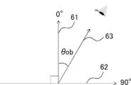
- FIG. 11 shows a schematic diagram for explaining the direction in which the central axis of the transmittance of the light absorption anisotropic layer is orthographically projected onto the film surface.
- the direction in which the transmittance central axis v of the light absorption anisotropic layer is normally projected onto the film surface is represented as v (xy).
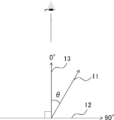
- ⁇ be the angle formed by the film normal direction (normal direction of the light absorption anisotropic layer) 13 and the transmittance central axis 11 of the light absorption anisotropic layer.
- the angle ⁇ is represented as an angle formed by the transmittance center axis v and the film normal direction (z-axis direction).
- FIG. 3 shows an arrangement of the axis arrangement of FIG. 2 as viewed from the film normal direction 13.
- ⁇ be the angle formed by the absorption axis direction of the polarizing element and the direction (line) 11b in which the central axis 11 of the transmittance of the light absorption anisotropic layer is normally projected onto the film surface.
- the angle ⁇ is represented as an angle formed by the orthographic projection direction v (xy) of the transmittance center axis and the absorption axis direction of the polarizing element (corresponding to the x-axis direction in FIG. 11). ing.
- the above angle ⁇ is represented by a positive angle value in the counterclockwise direction with respect to the absorption axis of the polarizing element, and is negative in the clockwise direction. It is expressed by the angle value of.
- the direction of the absorption axis of the extruder may be referred to as a vertical direction or a horizontal direction, but normally, in a state where the image display device is used, the direction of the side of the image display device close to the vertical direction is the vertical direction.
- the direction of the side of the image display device that is close to the horizontal direction is called the horizontal direction.
- the angle between the central axis of transmittance and the film normal is 0.1 to 45 °.
- the angle ⁇ between the direction in which the central axis of transmittance is projected onto the film surface and the absorption axis of the absorber is 0 ° or more and less than 85 °, more than 95 ° and less than 265 °, or more than 275 ° and 360 ° or less. There are no particular restrictions other than that.
- the transmittance central axis is defined as the direction having the highest transmittance when the transmittance is measured by changing the inclination angle and the inclination direction with respect to the film normal direction. More specifically, AxoScan OPMF-1 (manufactured by Optoscience) is used to measure the transmittance of the light absorption anisotropic layer at P-polarized light having a wavelength of 550 nm. More specifically, in the measurement, the azimuth angle at which the central axis of transmittance is tilted is first searched, and then the in-plane including the normal direction of the light absorption anisotropic layer along the azimuth angle.
- the polar angle which is the angle of the surface of the light absorption anisotropic layer with respect to the normal direction, is changed from 0 to 60 ° in 5 ° increments while changing the wavelength.
- the transmittance of the light absorption anisotropic layer is measured by injecting P-polarized light of 550 nm. As a result, the direction with the highest transmittance is defined as the central axis of transmittance.
- the center of the viewing angle of the image display device can be shifted not only vertically from the front but also in the left-right direction.
- the angle ⁇ between the central axis of transmittance and the normal line of the film is preferably 2 to 25 °.
- the central axis of transmittance of the light absorption anisotropic layer is tilted with respect to the normal line of the film surface, and the central axis of transmittance of the light absorption anisotropic layer is positive on the film surface.
- the angle ⁇ formed by the projected direction and the absorption axis of the polarizing element is preferably 30 to 60 °, 120 to 150 °, 210 to 240 °, or 300 to 330 °. The closer the angle is to 45 °, 135 °, 225 °, or 315 °, the reduction in the brightness in a specific direction of the image display device and the improvement in the brightness in another specific direction can be achieved at the same time.
- the brightness of the display on the passenger seat side is improved and the visibility is improved while ensuring the driver's field of view. Can be done.
- it is preferable to orient the dichroic substance having absorption in the visible region and the orientation of the liquid crystal compound is used to orient the organic dichroic substance. It is more preferable to make it.
- One example is a light absorption anisotropic layer in which at least one kind of organic dichroic substance is inclined or oriented with respect to the film normal direction (normal direction with respect to the surface of the light absorption anisotropic layer).
- Examples of the technology for orienting the organic dichroic substance as desired include a technique for producing a polarizing element using the organic dichroic substance and a technology for producing a guest-host liquid crystal cell.
- the technique used in the method for manufacturing a host-type liquid crystal display device can also be used for manufacturing the light absorption anisotropic layer used in the present invention.
- the molecule of the organic dichroic substance can be made to have the desired orientation as described above in association with the orientation of the host liquid crystal.
- the organic dichroic substance that serves as a guest and the rod-shaped liquid crystal compound that serves as the host liquid crystal are mixed to orient the host liquid crystal, and the molecules of the organic dichroic substance follow the orientation of the liquid crystal molecules.
- the light absorption anisotropic layer used in the present invention can be produced by orienting the liquid crystal and fixing the oriented state.
- the orientation of the organic dichroic substance by forming a chemical bond.
- the orientation can be fixed by advancing the polymerization of the host liquid crystal display, the organic dichroic substance, or the polymerizable component added as desired.
- the guest host type liquid crystal cell itself having a liquid crystal layer containing at least an organic dichroic substance and a host liquid crystal on a pair of substrates may be used as the light absorption anisotropic layer used in the present invention.
- the orientation of the host liquid crystal (and the orientation of the accompanying organic dichroic substance) can be controlled by the alignment layer formed on the inner surface of the substrate, and the orientation state is maintained unless an external stimulus such as an electric field is applied.
- the light absorption characteristics of the light absorption anisotropic layer used in the above can be made constant.
- the light absorption anisotropic layer used in the present invention can be obtained.
- a polymer film satisfying the required light absorption characteristics can be produced.
- a solution of an organic dichroic substance can be applied to the surface of a polymer film to allow the organic dichroic substance to permeate into the film to prepare a light absorption anisotropic layer.
- the orientation of the organic dichroic substance can be adjusted by the orientation of the polymer chain in the polymer film, its properties (chemical and physical properties such as the polymer chain or its functional group), the coating method, and the like. Details of this method are described in JP-A-2002-090526.
- the transmittance at a wavelength of 550 nm in the direction inclined by 30 ° from the central axis of transmittance is preferably 60% or less, more preferably 50% or less, still more preferably 45% or less. ..
- the lower limit is not particularly limited, but it is often 20% or more. This makes it possible to increase the contrast of the illuminance between the direction of the central axis of transmittance and the direction deviated from the central axis of transmittance, and the viewing angle can be sufficiently narrowed.
- the transmittance at a wavelength of 550 nm in the direction of the central axis of transmittance is preferably 65% or more, more preferably 75% or more, still more preferably 85% or more.
- the upper limit is not particularly limited, but it is often 95% or less.
- the light absorption anisotropic layer used in the present invention preferably contains a liquid crystal compound.
- the dichroic substance can be oriented with a high degree of orientation while suppressing the precipitation of the dichroic substance.
- the liquid crystal compound either a low-molecular-weight liquid crystal compound or a high-molecular-weight liquid crystal compound can be used, but it is preferable to use a high-molecular-weight liquid crystal compound because a high degree of orientation can be obtained. It is also preferable to use both a small molecule liquid crystal compound and a high molecular weight liquid crystal compound in combination.
- the "small molecule liquid crystal compound” means a liquid crystal compound having no repeating unit in the chemical structure.
- the "polymer liquid crystal compound” means a liquid crystal compound having a repeating unit in the chemical structure.
- Examples of the small molecule liquid crystal compound include the liquid crystal compound described in Japanese Patent Application Laid-Open No. 2013-228706.
- a small molecule liquid crystal compound exhibiting smectic properties is preferable in order to enhance the orientation.
- Small molecule liquid crystal compounds can generally be classified into rod-shaped type and disk-shaped type according to their shape.
- the rod-shaped liquid crystal compound is preferably a liquid crystal compound that does not exhibit dichroism in the visible region.
- the small molecule liquid crystal compound may be used alone or in combination of two or more.
- a liquid crystal compound represented by the formula (LC) is preferable.
- the liquid crystalline compound represented by the formula (LC) is a compound exhibiting liquid crystallinity.
- the liquid crystallinity may be a nematic phase or a smectic phase, and may exhibit both a nematic phase and a smectic phase, preferably at least a nematic phase.
- the smectic phase may be a higher-order smectic phase.
- the high-order smectic phase referred to here is the smectic B phase, the smectic D phase, the smectic E phase, the smectic F phase, the smectic G phase, the smectic H phase, the smectic I phase, the smectic J phase, the smectic K phase, and the smectic L. It is a phase, and among them, a smectic B phase, a smectic F phase, and a smectic I phase are preferable.
- the smectic liquid crystal phase exhibited by the liquid crystal compound is these higher-order smectic liquid crystal phases, a light absorption anisotropic layer having a higher degree of orientation order can be produced.
- the light absorption anisotropic layer prepared from the high-order smectic liquid crystal phase having a high degree of orientation order can obtain a Bragg peak derived from a high-order structure such as a hexatic phase or a crystal phase in X-ray diffraction measurement. ..
- the Bragg peak is a peak derived from the plane periodic structure of molecular orientation, and a light absorption anisotropic layer having a periodic interval of 3.0 to 5.0 ⁇ can be obtained.
- Q1 and Q2 are independently hydrogen atom, halogen atom, linear, branched or cyclic alkyl group having 1 to 20 carbon atoms, alkoxy group having 1 to 20 carbon atoms, and 1 to 20 carbon atoms, respectively.
- RP is a hydrogen atom, a halogen atom, a linear, branched or cyclic alkylene group having 1 to 10 carbon atoms, or an alkyl halide group having 1 to 20 carbon atoms.
- An alkoxy group having 1 to 20 carbon atoms, an alkenyl group having 1 to 20 carbon atoms, an alkynyl group having 1 to 20 carbon atoms, an aryl group having 1 to 20 carbon atoms, and a heterocyclic group may be called a heterocyclic group).
- Cyano group hydroxy group, nitro group, carboxy group, aryloxy group, silyloxy group, heterocyclic oxy group, acyloxy group, carbamoyloxy group, alkoxycarbonyloxy group, aryloxycarbonyloxy group, amino group (including anirino group) ), Ammonio group, acylamino group, aminocarbonylamino group, alkoxycarbonylamino group, aryloxycarbonylamino group, sulfamoylamino group, alkyl or arylsulfonylamino group, mercapto group, alkylthio group, arylthio group, heterocyclic thio group.
- Preferred embodiments of the crosslinkable group include a radically polymerizable group and a cationically polymerizable group.
- examples of the radically polymerizable group include a vinyl group represented by the above formula (P-1), a butadiene group represented by the above formula (P-2), and a (meth) acrylic represented by the above formula (P-4).
- the maleimide group represented by -12) is preferable.
- the cationically polymerizable group includes a vinyl ether group represented by the above formula (P-18), an epoxy group represented by the above formula (P-19), or an oxetanyl group represented by the above formula (P-20). Is preferable.
- S1 and S2 each independently represent a divalent spacer group, and preferred embodiments of S1 and S2 include the same structure as SPW in the above formula (W1). Omit.
- MG represents a mesogen group described later.
- the mesogen group represented by MG is a group showing the main skeleton of a liquid crystal molecule that contributes to the formation of a liquid crystal.
- the liquid crystal molecule exhibits liquid crystallinity, which is an intermediate state (mesophase) between the crystalline state and the isotropic liquid state.
- the mesogen group represented by MG preferably contains 2 to 10 cyclic structures, and more preferably 3 to 7 cyclic structures. Specific examples of the cyclic structure include aromatic hydrocarbon groups, heterocyclic groups, and alicyclic groups.
- the mesogen group represented by MG the following formula (MG-A) or the following formula is used because the expression of liquid crystallinity, adjustment of liquid crystal phase transition temperature, raw material availability and synthetic suitability, and the effect of the present invention are more excellent.
- the group represented by (MG-B) is preferable, and the group represented by the formula (MG-B) is more preferable.
- A1 is a divalent group selected from the group consisting of aromatic hydrocarbon groups, heterocyclic groups, and alicyclic groups. These groups may be substituted with a substituent such as the substituent S.
- the divalent group represented by A1 is preferably a 4- to 15-membered ring. Further, the divalent group represented by A1 may be a monocyclic ring or a condensed ring. * Represents the bonding position with S1 or S2.
- Examples of the divalent aromatic hydrocarbon group represented by A1 include a phenylene group, a naphthylene group, a fluorene-diyl group, an anthracene-diyl group, a tetracene-diyl group, and the like.
- a phenylene group or a naphthylene group is preferable from the viewpoint of availability.
- the divalent heterocyclic group represented by A1 may be either aromatic or non-aromatic, but a divalent aromatic heterocyclic group is preferable from the viewpoint of further improving the degree of orientation. ..
- Examples of the atom other than carbon constituting the divalent aromatic heterocyclic group include a nitrogen atom, a sulfur atom and an oxygen atom.
- the aromatic heterocyclic group has a plurality of atoms constituting a ring other than carbon, they may be the same or different.
- divalent aromatic heterocyclic group examples include pyridylene group (pyridine-diyl group), pyridazine-diyl group, imidazole-diyl group, thienylene (thiophene-diyl group), and quinolylene group (quinolin-diyl group).
- Isoquinolylene group isoquinolin-diyl group
- oxazole-diyl group thiazole-diyl group
- oxadiazol-diyl group benzothiazole-diyl group
- benzothiazol-diyl group benzothiazol-diyl group
- phthalimide-diyl group thienothiazole-diyl group
- Thiazolothiazole-diyl group, thienothiophene-diyl group, thienooxazol-diyl group and the following structures (II-1) to (II-4) and the like.
- D 1 represents —S—, —O—, or NR 11 ⁇
- R 11 represents a hydrogen atom or an alkyl group having 1 to 6 carbon atoms
- Y 1 represents an aromatic hydrocarbon group having 6 to 12 carbon atoms or an aromatic heterocyclic group having 3 to 12 carbon atoms
- Z 1 , Z 2 and Z 3 are independent hydrogen atoms or carbon atoms, respectively.
- R 13 or SR 12 , Z 1 and Z 2 may combine with each other to form an aromatic ring or an aromatic heterocycle, where R 12 and R 13 are independent hydrogen atoms or 1 to 1 to carbon atoms, respectively.
- J 1 and J 2 are each independently, -O -, - NR 21 - , (R 21 represents a hydrogen atom or a substituent.)
- R 21 represents a hydrogen atom or a substituent.
- E represents a hydrogen atom or a non-metal atom of Groups 14 to 16 to which a substituent may be bonded
- Jx consists of an aromatic hydrocarbon ring and an aromatic heterocycle.
- It represents an organic group having 2 to 30 carbon atoms and having at least one aromatic ring selected from the group consisting of a group hydrocarbon ring and an aromatic heterocycle, and the aromatic rings of Jx and Jy have a substituent. Also, Jx and Jy may be bonded to form a ring, and D 2 represents a hydrogen atom or an alkyl group having 1 to 6 carbon atoms which may have a substituent.
- Y 1 when Y 1 is an aromatic hydrocarbon group having 6 to 12 carbon atoms, it may be monocyclic or polycyclic. When Y 1 is an aromatic heterocyclic group having 3 to 12 carbon atoms, it may be monocyclic or polycyclic.
- J 1 and J 2 when J 1 and J 2 represent ⁇ NR 21 ⁇ , the description in paragraphs 0035 to 0045 of JP-A-2008-107767 can be referred to as the substituent of R 21, for example. This content is incorporated herein by reference.
- R' is preferable.
- R' represents a substituent, and as the substituent, for example, the description in paragraphs [0035] to [0045] of JP-A-2008-107767 can be referred to, and -NZ A1 Z A2 (Z A1 and Z A 2 are respectively). Independently, it represents a hydrogen atom, an alkyl group or an aryl group).
- divalent alicyclic group represented by A1 include a cyclopentylene group and a cyclohexylene group, and the carbon atoms are -O-, -Si (CH 3 ) 2- , and -N (. Z)-(Z represents hydrogen, an alkyl group having 1 to 4 carbon atoms, a cycloalkyl group, an aryl group, a cyano group, or a halogen atom), -C (O)-, -S-, -C. (S)-, -S (O)-, and -SO 2- , may be substituted with a group in which two or more of these groups are combined.
- a1 represents an integer of 2 to 10.
- the plurality of A1s may be the same or different.
- A2 and A3 are each independently a divalent group selected from the group consisting of an aromatic hydrocarbon group, a heterocyclic group and an alicyclic group. Since the specific examples and preferred embodiments of A2 and A3 are the same as those of A1 of the formula (MG-A), the description thereof will be omitted.
- a2 represents an integer of 1 to 10, and a plurality of A2s may be the same or different, and a plurality of LA1s may be the same or different. It is more preferable that a2 is 2 or more because the effect of the present invention is more excellent.
- LA1 is a single bond or divalent linking group.
- LA1 is a divalent linking group
- a2 is 2 or more
- at least one of the plurality of LA1s is a divalent linking group.
- the divalent linking group represented by LA1 is the same as LW, and thus the description thereof will be omitted.
- MG include the following structures, and in the following structures, hydrogen atoms on an aromatic hydrocarbon group, a heterocyclic group and an alicyclic group are substituted with the above-mentioned substituent S. May be good.
- Preferred embodiments of the cyclic structure of the mesogen group MG include a cyclohexylene group, a cyclopentylene group, a phenylene group, a naphthylene group, a fluorene-diyl group, a pyridine-diyl group, a pyridazine-diyl group, a thiophen-diyl group, and an oxazole-. Examples thereof include a diyl group, a thiazole-diyl group, and a thienothiophene-diyl group, and the number of cyclic structures is preferably 2 to 10, more preferably 3 to 7.
- Preferred embodiments of the substituent S having a mesogen structure include a halogen atom, an alkyl halide group, a cyano group, a hydroxy group, a nitro group, a carboxy group, an alkoxy group having 1 to 10 carbon atoms, and an alkylcarbonyl group having 1 to 10 carbon atoms.
- Examples thereof include a group having a single bond, SPW being a divalent spacer group, and Q being a crosslinkable group represented by (P1) to (P30) described above, and examples of the crosslinkable group are vinyl groups. , Butadiene group, (meth) acrylic group, (meth) acrylamide group, vinyl acetate group, fumaric acid ester group, styryl group, vinylpyrrolidone group, maleic anhydride, maleimide group, vinyl ether group, epoxy group, or oxetanyl group. preferable.
- the divalent spacer groups S1 and S2 are the same as those of the SPW, the description thereof will be omitted.
- the number of carbon atoms of the spacer group is preferably 6 or more, and further 8 or more. preferable.
- a plurality of small molecule liquid crystal compounds may be used in combination, preferably 2 to 6 types in combination, and more preferably 2 to 4 types in combination.
- a small molecule liquid crystal compound in combination By using a small molecule liquid crystal compound in combination, the solubility can be improved and the phase transition temperature of the liquid crystal composition can be adjusted.
- the small molecule liquid crystal compound examples include compounds represented by the following formulas (LC-1) to (LC-77), but the small molecule liquid crystal compound is not limited thereto.
- polymer liquid crystal compound examples include thermotropic liquid crystal polymers described in JP-A-2011-237513. Further, the polymer liquid crystal compound preferably has a repeating unit having a crosslinkable group at the terminal from the viewpoint of excellent strength (particularly, bending resistance) of the light absorption anisotropic layer.
- crosslinkable group examples include the polymerizable group described in paragraphs [0040] to [0050] of JP-A-2010-244038.
- an acryloyl group, a methacryloyl group, an epoxy group, an oxetanyl group, or a styryl group is preferable, and an acryloyl group or a methacryloyl group is more preferable, from the viewpoint of improving reactivity and synthetic suitability.
- the polymer liquid crystal compound may exhibit a smectic liquid crystal phase or a nematic liquid crystal phase, preferably a nematic liquid crystal phase.
- the temperature range indicating the nematic liquid crystal phase is preferably room temperature (23 ° C.) to 450 ° C., and preferably 50 to 400 ° C. from the viewpoint of handling and manufacturing suitability.
- the content of the liquid crystal compound is preferably 25 to 2000 parts by mass, more preferably 100 to 1300 parts by mass, and 200 to 900 parts by mass with respect to 100 parts by mass of the content of the dichroic substance in the light absorption anisotropic layer. Parts by mass are more preferred.
- the liquid crystal compound may be contained alone or in combination of two or more. When two or more kinds of liquid crystal compounds are contained, the content of the liquid crystal compounds means the total content of the liquid crystal compounds.
- the liquid crystal compound is preferably a polymer liquid crystal compound containing a repeating unit represented by the following formula (1L) (hereinafter, also referred to as “repeating unit (1L)”) because the degree of orientation is more excellent.
- P1 represents the main chain of the repeating unit
- L1 represents a single bond or a divalent linking group
- SP1 represents a spacer group
- M1 represents a mesogen group
- T1 represents a terminal group. ..
- main chain of the repeating unit represented by P1 include groups represented by the following formulas (P1-A) to (P1-D), and among them, a monomer as a raw material. From the viewpoint of versatility and ease of handling, the group represented by the following formula (P1-A) is preferable.
- R 1 , R 2 , R 3 and R 4 are independently hydrogen atoms, halogen atoms, alkyl groups having 1 to 10 carbon atoms or 1 to 10 carbon atoms, respectively.
- the alkyl group may be a linear or branched alkyl group, or may be an alkyl group having a cyclic structure (cycloalkyl group). Further, the number of carbon atoms of the above alkyl group is preferably 1 to 5.
- the group represented by the formula (P1-A) is preferably one unit of the partial structure of the poly (meth) acrylic acid ester obtained by the polymerization of the (meth) acrylic acid ester.
- the group represented by the formula (P1-B) is preferably an ethylene glycol unit formed by ring-opening polymerization of the epoxy group of the compound having an epoxy group.
- the group represented by the formula (P1-C) is preferably a propylene glycol unit formed by ring-opening polymerization of the oxetane group of the compound having an oxetane group.
- the group represented by the formula (P1-D) is preferably a siloxane unit of a polysiloxane obtained by the condensation polymerization of a compound having at least one of an alkoxysilyl group and a silanol group.
- examples of the compound having at least one of the alkoxysilyl group and the silanol group include compounds having a group represented by the formula SiR 4 (OR 5 ) 2-.
- R 4 is, (P1-D) has the same meaning as R 4 in each plurality of R 5 independently represent a hydrogen atom or an alkyl group having 1 to 10 carbon atoms.
- L1 is a single bond or divalent linking group.
- the divalent linking groups represented by L1 are -C (O) O-, -OC (O)-, -O-, -S-, -C (O) NR 3- , -NR 3 C (O). -, - SO 2 -, and, -NR 3 R 4 -, and the like.
- R 3 and R 4 each independently represent a hydrogen atom and an alkyl group having 1 to 6 carbon atoms which may have a substituent W described later.
- P1 is a group represented by the formula (P1-A)
- L1 is preferably a group represented by —C (O) O— for the reason that the degree of orientation is more excellent.
- P1 is a group represented by the formulas (P1-B) to (P1-D)
- L1 is preferably a single bond for the reason that the degree of orientation is more excellent.
- the spacer group represented by SP1 is at least one selected from the group consisting of an oxyethylene structure, an oxypropylene structure, a polysiloxane structure and a fluorinated alkylene structure because of its tendency to exhibit liquid crystallinity and the availability of raw materials. It preferably contains the structure of the species.
- oxyethylene structure represented by SP1 is, * - (CH 2 -CH 2 O) n1 - * groups represented by are preferred.
- n1 represents an integer of 1 to 20, and * represents a coupling position with L1 or M1 in the above formula (1L). From the viewpoint of better orientation, n1 is preferably an integer of 2 to 10, more preferably an integer of 2 to 4, and even more preferably 3.
- the oxypropylene structure represented by SP1 is preferably a group represented by *-(CH (CH 3 ) -CH 2 O) n2- * because the degree of orientation is more excellent.
- n2 represents an integer of 1 to 3
- * represents the coupling position with L1 or M1.
- the polysiloxane structure represented by SP1 is preferably a group represented by *-(Si (CH 3 ) 2- O) n3- * because the degree of orientation is more excellent.
- n3 represents an integer of 6 to 10
- * represents the coupling position with L1 or M1.
- alkylene fluoride structure represented by SP1 for reasons of orientation more excellent, * - (CF 2 -CF 2 ) n4 - * groups represented by are preferred.
- n4 represents an integer of 6 to 10
- * represents the coupling position with L1 or M1.
- the mesogen group represented by M1 is a group showing the main skeleton of a liquid crystal molecule that contributes to the formation of a liquid crystal.
- the liquid crystal molecule exhibits liquid crystallinity, which is an intermediate state (mesophase) between the crystalline state and the isotropic liquid state.
- mesogen group for example, "Frussige Crystal in Tablelen II” (VEB Manual Verlag fur Grundstoff Industrie, Leipzig, 1984), especially the description on pages 7 to 16 and the liquid crystal, and the liquid crystal. You can refer to the edition, LCD Handbook (Maruzen, 2000), especially the description in Chapter 3.
- the mesogen group for example, a group having at least one cyclic structure selected from the group consisting of an aromatic hydrocarbon group, a heterocyclic group, and an alicyclic group is preferable.
- the mesogen group preferably has an aromatic hydrocarbon group, more preferably 2 to 4 aromatic hydrocarbon groups, and has 3 aromatic hydrocarbon groups, for the reason that the degree of orientation is more excellent. Is more preferable.
- the mesogen group the following formula (M1-A) or the following formula (M1-B) is used from the viewpoints of developing liquid crystallinity, adjusting the liquid crystal phase transition temperature, availability of raw materials and synthetic suitability, and more excellent orientation. ) Is preferable, and the group represented by the formula (M1-B) is more preferable.
- A1 is a divalent group selected from the group consisting of aromatic hydrocarbon groups, heterocyclic groups and alicyclic groups. These groups may be substituted with an alkyl group, an alkyl fluoride group, an alkoxy group or a substituent W described later.
- the divalent group represented by A1 is preferably a 4- to 6-membered ring. Further, the divalent group represented by A1 may be a monocyclic ring or a condensed ring. * Represents the binding position with SP1 or T1.
- Examples of the divalent aromatic hydrocarbon group represented by A1 include a phenylene group, a naphthylene group, a fluorene-diyl group, an anthracene-diyl group, a tetracene-diyl group, and the like. From the viewpoint of properties and the like, a phenylene group or a naphthylene group is preferable, and a phenylene group is more preferable.
- the divalent heterocyclic group represented by A1 may be either aromatic or non-aromatic, but a divalent aromatic heterocyclic group is preferable from the viewpoint of further improving the degree of orientation. ..
- Examples of the atom other than carbon constituting the divalent aromatic heterocyclic group include a nitrogen atom, a sulfur atom and an oxygen atom.
- the aromatic heterocyclic group has a plurality of atoms constituting a ring other than carbon, they may be the same or different.
- divalent aromatic heterocyclic group examples include pyridylene group (pyridine-diyl group), pyridazine-diyl group, imidazole-diyl group, thienylene (thiophene-diyl group), and quinolylene group (quinolin-diyl group).
- Isoquinolylene group isoquinolin-diyl group
- oxazole-diyl group thiazole-diyl group
- oxadiazol-diyl group benzothiazole-diyl group
- benzothiazol-diyl group benzothiazol-diyl group
- phthalimide-diyl group thienothiazole-diyl group
- divalent alicyclic group represented by A1 examples include a cyclopentylene group and a cyclohexylene group.
- a1 represents an integer from 1 to 10.
- the plurality of A1s may be the same or different.
- A2 and A3 are each independently a divalent group selected from the group consisting of aromatic hydrocarbon groups, heterocyclic groups and alicyclic groups. Specific examples and preferred embodiments of A2 and A3 are the same as those of A1 of the formula (M1-A), and thus the description thereof will be omitted.
- a2 represents an integer of 1 to 10, and when a2 is 2 or more, a plurality of A2s may be the same or different, and a plurality of A3s may be the same or different. Often, the plurality of LA1s may be the same or different.
- a2 is preferably an integer of 2 or more, and more preferably 2 for the reason that the degree of orientation is more excellent.
- LA1 is a divalent linking group.
- the plurality of LA1s are independently single-bonded or divalent linking groups, and at least one of the plurality of LA1s is a divalent linking group.
- a2 is 2 or more, it is preferable that one of the two LA1s is a divalent linking group and the other is a single bond because the degree of orientation is better.
- M1 include the following structures.
- Ac represents an acetyl group.
- the terminal group represented by T1 includes a hydrogen atom, a halogen atom, a cyano group, a nitro group, a hydroxy group, an alkyl group having 1 to 10 carbon atoms, an alkoxy group having 1 to 10 carbon atoms, and an alkylthio group having 1 to 10 carbon atoms.
- Examples thereof include a ureido group having a number of 1 to 10 and a (meth) acryloyloxy group-containing group.
- Examples of the (meth) acryloyloxy group-containing group include -LA (L represents a single bond or a linking group. Specific examples of the linking group are the same as those of L1 and SP1 described above.
- A is (meth).
- a group represented by (representing an acryloyloxy group) can be mentioned.
- T1 an alkoxy group having 1 to 10 carbon atoms is preferable, an alkoxy group having 1 to 5 carbon atoms is more preferable, and a methoxy group is further preferable, because the degree of orientation is more excellent.
- These terminal groups may be further substituted with these groups or the crosslinkable groups described above.
- the number of atoms in the main chain of T1 is preferably 1 to 20, more preferably 1 to 15, further preferably 1 to 10, and particularly preferably 1 to 7 because the degree of orientation is more excellent. When the number of atoms in the main chain of T1 is 20 or less, the degree of orientation of the light absorption anisotropic layer is further improved.
- the "main chain” in T1 means the longest molecular chain bonded to M1, and the hydrogen atom is not counted in the number of atoms in the main chain of T1.
- the number of atoms in the main chain is 4, and when T1 is a sec-butyl group, the number of atoms in the main chain is 3.
- the content of the repeating unit (1 L) is preferably 20 to 100% by mass with respect to 100% by mass of all the repeating units of the polymer liquid crystal compound from the viewpoint of more excellent orientation.
- the content of each repeating unit contained in the polymer liquid crystal compound is calculated based on the charged amount (mass) of each monomer used to obtain each repeating unit.
- the repeating unit (1 L) may be contained alone or in combination of two or more in the polymer liquid crystal compound. Among them, it is preferable that two kinds of repeating units (1 L) are contained in the polymer liquid crystal compound for the reason that the degree of orientation is more excellent.
- the terminal group represented by T1 in one (repeating unit A) is an alkoxy group and the other (repeating unit B) is from the viewpoint of better orientation. It is preferable that the terminal group represented by T1 is a group other than the alkoxy group.
- the terminal group represented by T1 in the repeating unit B is preferably an alkoxycarbonyl group, a cyano group, or a (meth) acryloyloxy group-containing group, and is preferably an alkoxycarbonyl group or a cyano group, from the viewpoint of having a better degree of orientation. It is more preferable that it is a group.
- the ratio (A / B) of the content of the repeating unit A in the polymer liquid crystal compound and the content of the repeating unit B in the polymer liquid crystal compound is 50/50 because the degree of orientation is more excellent. It is preferably ⁇ 95/5, more preferably 60/40 to 93/7, and even more preferably 70/30 to 90/10.
- the polymer liquid crystal compound may have a repeating unit (1 L) and a repeating unit having no mesogen group.
- the repeating unit having no mesogen group include a repeating unit in which M1 in the formula (1L) is a single bond.
- the repeating unit having no mesogen group has a radically polymerizable group at the terminal.
- the polymer liquid crystal compound has a repeating unit having no mesogen group, it is more than 0% by mass and 30% by mass or less with respect to 100% by mass of all the repeating units of the polymer liquid crystal compound because the degree of orientation is better. Is preferable, and more than 10% by mass and 20% by mass or less is more preferable.
- the weight average molecular weight (Mw) of the polymer liquid crystal compound is preferably 1000 to 500,000, more preferably 2000 to 300,000 from the viewpoint of more excellent degree of orientation.
- the handling of the polymer liquid crystal compound becomes easy.
- the weight average molecular weight (Mw) of the polymer liquid crystal compound is preferably 10,000 or more, and more preferably 10,000 to 300,000.
- the weight average molecular weight (Mw) of the polymer liquid crystal compound is preferably less than 10,000, more preferably 2000 or more and less than 10,000.
- the weight average molecular weight and the number average molecular weight in the present invention are values measured by a gel permeation chromatograph (GPC) method.
- the substituent W in the present specification will be described.
- the substituent W is, for example, an alkyl group (preferably an alkyl group having 1 to 20 carbon atoms, more preferably 1 to 12 carbon atoms, still more preferably an alkyl group having 1 to 8 carbon atoms, and for example, a methyl group or an ethyl group.
- alkyl group preferably an alkyl group having 1 to 20 carbon atoms, more preferably 1 to 12 carbon atoms, still more preferably an alkyl group having 1 to 8 carbon atoms, and for example, a methyl group or an ethyl group.
- Examples include isopropyl group, tert-butyl group, n-octyl group, n-decyl group, n-hexadecyl group, cyclopropyl group, cyclopentyl group, cyclohexyl group and the like), alkenyl group (preferably 2 to 2 carbon atoms).
- An alkynyl group preferably an alkynyl group having 2 to 20 carbon atoms, more preferably 2 to 12 carbon atoms, still more preferably a 2 to 8 carbon atoms, and examples thereof include a propargyl group and a 3-pentynyl group.
- An aryl group (preferably an aryl group having 6 to 30 carbon atoms, more preferably 6 to 20 carbon atoms, still more preferably 6 to 12 carbon atoms, for example, a phenyl group, a 2,6-diethylphenyl group, and the like. Examples include 3,5-ditrifluoromethylphenyl group, styryl group, naphthyl group, biphenyl group and the like, substituted or unsubstituted amino group (preferably 0 to 20 carbon atoms, more preferably 0 to 0 carbon atoms).
- an amino group having 0 to 6 carbon atoms for example, an unsubstituted amino group, a methylamino group, a dimethylamino group, a diethylamino group, an anilino group and the like), an alkoxy group (preferably. It has 1 to 20 carbon atoms, more preferably 1 to 15 carbon atoms, and examples thereof include a methoxy group, an ethoxy group, a butoxy group, and the like, and an oxycarbonyl group (preferably 2 to 20 carbon atoms, more preferably.
- An alkoxycarbonylamino group preferably 2 to 20 carbon atoms, more preferably 2 to 10 carbon atoms, still more preferably 2 to 6 carbon atoms, and examples thereof include a methoxycarbonylamino group), aryloxy.
- a carbonylamino group (preferably 7 to 20 carbon atoms, more preferably 7 to 16 carbon atoms, still more preferably 7 to 12 carbon atoms, and examples thereof include a phenyloxycarbonylamino group), a sulfonylamino group ( It preferably has 1 to 20 carbon atoms, more preferably 1 to 10 carbon atoms, still more preferably 1 to 6 carbon atoms, and examples thereof include a methanesulfonylamino group and a benzenesulfonylamino group), and a sulfamoyl group.
- a carbamoyl group (preferably 1 to 20 carbon atoms, more preferably 1 to 10 carbon atoms, still more preferably 1 to 6 carbon atoms, for example, an unsubstituted carbamoyl group, methyl.
- Carbamoyl group, diethylcarbamoyl group, phenylcarbamoyl group and the like can be mentioned.
- Alkylthio group preferably 1 to 20 carbon atoms, more preferably 1 to 10 carbon atoms, still more preferably 1 to 6 carbon atoms.
- a methylthio group, an ethylthio group, etc. an arylthio group (preferably 6 to 20 carbon atoms, more preferably 6 to 16 carbon atoms, still more preferably 6 to 12 carbon atoms, for example, phenylthio.
- a group and the like can be mentioned.
- a sulfonyl group preferably 1 to 20 carbon atoms, more preferably 1 to 10 carbon atoms, still more preferably 1 to 6 carbon atoms, and examples thereof include a mesyl group and a tosyl group.
- Sulfinyl group preferably 1 to 20 carbon atoms, more preferably 1 to 10 carbon atoms, still more preferably 1 to 6 carbon atoms, and examples thereof include a methanesulfinyl group and a benzenesulfinyl group.
- Ureid group preferably 1 to 20 carbon atoms, more preferably 1 to 10 carbon atoms, still more preferably 1 to 6 carbon atoms, for example, an unsubstituted ureido group, a methyl ureido group, and a phenyl.
- Examples include ureido groups), phosphate amide groups (preferably 1 to 20 carbon atoms, more preferably 1 to 10 carbon atoms, etc.). More preferably, it has 1 to 6 carbon atoms, and examples thereof include a diethyl phosphate amide group and a phenyl phosphate amide group.
- a heterocyclic group, an azo group, or a heterocyclic group preferably a heterocyclic group having 1 to 30 carbon atoms, more preferably 1 to 12 carbon atoms, and having a heterocyclic atom such as a nitrogen atom, an oxygen atom, or a sulfur atom.
- Examples of the group include an epoxy group, an oxetanyl group, an imidazolyl group, a pyridyl group, a quinolyl group, a frill group, a piperidyl group, a morpholino group, a maleimide group, a benzoxazolyl group, a benzimidazolyl group, and a benzthiazolyl group.
- a silyl group (preferably a silyl group having 3 to 40 carbon atoms, more preferably 3 to 30 carbon atoms, still more preferably a silyl group having 3 to 24 carbon atoms, such as a trimethylsilyl group and a triphenylsilyl group. ), A carboxy group, a sulfonic acid group, a phosphoric acid group and the like.
- the light absorption anisotropic layer used in the present invention preferably contains a dichroic substance.
- the bicolor substance is not particularly limited, and is a visible light absorbing substance (bicolor dye, bicolor azo dye compound), a light emitting substance (fluorescent substance, phosphorescent substance), an ultraviolet absorbing substance, an infrared absorbing substance, and a nonlinear optical substance. , Carbon nanotubes, inorganic substances (for example, quantum rods) and the like, and conventionally known bicolor substances (bicolor substances) can be used.
- dichroic substance an organic dichroic substance is preferable, and a dichroic azo dye compound is more preferable.
- the dichroic azo dye compound is not particularly limited, and conventionally known dichroic azo dyes can be used, but the compounds described below are preferably used.
- the dichroic azo dye compound means a dye having different absorbance depending on the direction.
- the dichroic azo dye compound may or may not exhibit liquid crystallinity.
- the dichroic azo dye compound When the dichroic azo dye compound exhibits liquid crystallinity, it may exhibit either nematic property or smectic property.
- the temperature range indicating the liquid crystal phase is preferably room temperature (about 20 to 28 ° C.) to 300 ° C., and more preferably 50 to 200 ° C. from the viewpoint of handleability and manufacturing suitability.
- the light absorption anisotropic layer has at least one dye compound having a maximum absorption wavelength in the wavelength range of 560 to 700 nm (hereinafter, “first dichroic azo dye”). Also abbreviated as “compound”) and at least one dye compound having a maximum absorption wavelength in the wavelength range of 455 nm or more and less than 560 nm (hereinafter, also abbreviated as "second dichroic azo dye compound”). More preferably, it contains at least a dichroic azo dye compound represented by the formula (1) described later and a dichroic azo dye compound represented by the formula (2) described later. ..
- three or more kinds of dichroic azo dye compounds may be used in combination.
- the first dichroic azo dye compound and the second dichroic azo dye compound are used.
- the dichroic azo dye compound of No. 1 and at least one dye compound having a maximum absorption wavelength in the wavelength range of 380 nm or more and less than 455 nm are used.
- the dichroic azo dye compound of No. 1 and at least one dye compound having a maximum absorption wavelength in the wavelength range of 380 nm or more and less than 455 nm hereinafter, also abbreviated as “third dichroic azo dye compound”. Is preferable.
- the dichroic azo dye compound preferably has a crosslinkable group from the viewpoint of improving the pressing resistance.
- the crosslinkable group include (meth) acryloyl group, epoxy group, oxetanyl group, styryl group and the like, and among them, (meth) acryloyl group is preferable.
- the first dichroic azo dye compound is preferably a compound having a chromophore as a nucleus and a side chain attached to the end of the chromophore.
- the color-developing group include an aromatic ring group (for example, an aromatic hydrocarbon group and an aromatic heterocyclic group), an azo group, and the like, and a structure having both an aromatic ring group and an azo group can be mentioned.
- a bisazo structure having an aromatic heterocyclic group (preferably a thienothiazole group) and two azo groups is more preferable.
- the side chain is not particularly limited, and examples thereof include groups represented by R1, R2, or R3 of the formula (1) described later.
- the first dichroic azo dye compound is a dichroic azo dye compound having a maximum absorption wavelength in the wavelength range of 560 to 700 nm, and has a wavelength of 560 to 650 nm from the viewpoint of adjusting the color of the light absorption anisotropic layer.
- a dichroic azo dye compound having a maximum absorption wavelength in the range of 560 to 640 nm is preferable, and a dichroic azo dye compound having a maximum absorption wavelength in the wavelength range of 560 to 640 nm is more preferable.
- the maximum absorption wavelength (nm) of the dichroic azo dye compound in the present specification is a wavelength of 380 to 800 nm measured by a spectrophotometer using a solution in which the dichroic azo dye compound is dissolved in a good solvent. Obtained from the ultraviolet visible light spectrum in the range.
- the first dichroic azo dye compound is preferably a compound represented by the following formula (1) from the viewpoint of further improving the degree of orientation of the formed light absorption anisotropic layer. ..
- Ar1 and Ar2 each independently represent a phenylene group which may have a substituent or a naphthylene group which may have a substituent, and a phenylene group is preferable.
- R1 is a hydrogen atom, a linear or branched alkyl group which may have a substituent having 1 to 20 carbon atoms, an alkoxy group, an alkylthio group, an alkylsulfonyl group, an alkylcarbonyl group, and the like.
- R1 is a group other than a hydrogen atom
- R1' represents a hydrogen atom or a linear or branched alkyl group having 1 to 6 carbon atoms. When a plurality of R1'are present in each group, they may be the same or different from each other.
- R2 and R3 independently have a hydrogen atom and a linear or branched alkyl group which may have a substituent having 1 to 20 carbon atoms, an alkoxy group, an acyl group, and an alkyloxy.
- -CH 2- constituting the above alkyl group is -O-, -S-, -C (O)-, -C (O) -O-, -OC (O)-, -C (O).
- R2 and R3 are groups other than hydrogen atoms
- the hydrogen atoms of each group are halogen atom, nitro group, cyano group, -OH group, -N (R2') 2 , amino group, -C (R2').
- ) C (R2')-NO 2
- -C (R2') C (R2')-CN
- -C (R2') C (CN) 2 .
- R2' represents a hydrogen atom or a linear or branched alkyl group having 1 to 6 carbon atoms.
- R2 and R3 may be bonded to each other to form a ring, and R2 or R3 may be bonded to Ar2 to form a ring.
- R1 is preferably an electron-attracting group
- R2 and R3 are preferably groups having low electron donating properties.
- R1 includes an alkylsulfonyl group, an alkylcarbonyl group, an alkyloxycarbonyl group, an acyloxy group, an alkylsulfonylamino group, an alkylsulfamoyl group, an alkylsulfinyl group, an alkylureido group and the like.
- R2 and R3 include groups having the following structures. The group having the following structure is shown in the above formula (1) in a form containing a nitrogen atom to which R2 and R3 are bonded.
- the second dichroic azo dye compound is a compound different from the first dichroic azo dye compound, and specifically, its chemical structure is different.
- the second dichroic azo dye compound is preferably a compound having a chromophore, which is the core of the dichroic azo dye compound, and a side chain attached to the end of the chromophore.
- Specific examples of the color-developing group include an aromatic ring group (for example, an aromatic hydrocarbon group and an aromatic heterocyclic group), an azo group, and the like, and a structure having both an aromatic hydrocarbon group and an azo group is preferable.
- a bisazo or trisazo structure having an aromatic hydrocarbon group and two or three azo groups is more preferred.
- the side chain is not particularly limited, and examples thereof include a group represented by R4, R5 or R6 of the formula (2) described later.
- the second dichroic azo dye compound is a dichroic azo dye compound having a maximum absorption wavelength in the wavelength range of 455 nm or more and less than 560 nm, and has a wavelength of 455 to 455 to be obtained from the viewpoint of adjusting the color of the light absorption anisotropic layer.
- a dichroic azo dye compound having a maximum absorption wavelength in the range of 555 nm is preferable, and a dichroic azo dye compound having a maximum absorption wavelength in the wavelength range of 455 to 550 nm is more preferable.
- first dichroic azo dye compound having a maximum absorption wavelength in the range of 560 to 700 nm and a second dichroic azo dye compound having a maximum absorption wavelength in the range of 455 nm or more and less than 560 nm are used. , It becomes easier to adjust the color of the light absorption anisotropic layer.
- the second dichroic azo dye compound is preferably a compound represented by the formula (2) from the viewpoint of further improving the degree of orientation of the light absorption anisotropic layer.
- n 1 or 2.
- Ar3, Ar4 and Ar5 independently have a phenylene group which may have a substituent, a naphthylene group which may have a substituent or a heterocycle which may have a substituent.
- the heterocyclic group may be either aromatic or non-aromatic. Examples of the atom other than carbon constituting the aromatic heterocyclic group include a nitrogen atom, a sulfur atom and an oxygen atom.
- the aromatic heterocyclic group has a plurality of atoms constituting a ring other than carbon, they may be the same or different.
- aromatic heterocyclic group examples include pyridylene group (pyridine-diyl group), pyridazine-diyl group, imidazole-diyl group, thienylene (thiophene-diyl group), quinolylene group (quinolin-diyl group), and isoquinolylene.
- R4 in the formula (2) is the same as that of R1 in the formula (1).
- R5 and R6 in the formula (2) are the same as those of R2 and R3 in the formula (1), respectively.
- R4 is preferably an electron-attracting group
- R5 and R6 are preferably groups having low electron donating properties.
- the specific example when R4 is an electron-attracting group is the same as the specific example when R1 is an electron-attracting group
- R5 and R6 are groups having low electron donating property.
- the specific example in the case of is the same as the specific example in the case where R2 and R3 are groups having a low electron donating property.
- the logP value is an index expressing the hydrophilic and hydrophobic properties of the chemical structure.
- the absolute value of the difference between the logP value of the side chain of the first dichroic azo dye compound and the logP value of the side chain of the second dichroic azo dye compound (hereinafter, also referred to as "logP difference"). Is preferably 2.30 or less, more preferably 2.0 or less, further preferably 1.5 or less, and particularly preferably 1.0 or less.
- the logP difference is 2.30 or less, the affinity between the first dichroic azo dye compound and the second dichroic azo dye compound is enhanced, and it becomes easier to form the sequence structure, so that light absorption occurs.
- the degree of orientation of the anisotropic layer is further improved.
- the side chain of the first dichroic azo dye compound and the second dichroic azo dye compound means a group bonded to the end of the above-mentioned chromophore.
- the first dichroic azo dye compound is a compound represented by the formula (1)
- R1, R2 and R3 in the formula (1) are side chains and the second dichroic azo dye.
- R4, R5 and R6 in the formula (2) are side chains.
- the first dichroic azo dye compound is a compound represented by the formula (1) and the second dichroic azo dye compound is a compound represented by the formula (2)
- R1 and R4 Of the difference in logP value between R1 and R5, the difference in logP value between R2 and R4, and the difference in logP value between R2 and R5, at least one logP difference has the above value. It is preferable to meet.
- the logP value is an index expressing the hydrophilic and hydrophobic properties of the chemical structure, and is sometimes called a prohydrophobic parameter.
- the logP value can be calculated using software such as ChemBioDraw Ultra or HSPiP (Ver. 4.1.07).
- OECD Guidelines for the Testing of Chemicals, Sections 1, Test No. It can also be obtained experimentally by the method of 117 or the like.
- a value calculated by inputting the structural formula of the compound into HSPiP (Ver. 4.1.07) is adopted as the logP value.
- the third bicolor azo dye compound is a bicolor azo dye compound other than the first bicolor azo dye compound and the second bicolor azo dye compound, and specifically, the first two.
- the chemical structure is different from that of the chromatic azo dye compound and the second dichromatic azo dye compound.
- the light absorption anisotropic layer contains a third dichroic azo dye compound, there is an advantage that the tint of the light absorption anisotropic layer can be easily adjusted.
- the maximum absorption wavelength of the third dichroic azo dye compound is 380 nm or more and less than 455 nm, preferably 385 to 454 nm.
- a dichroic azo dye represented by the following formula (6) is preferable.
- a and B each independently represent a crosslinkable group.
- a and b independently represent 0 or 1, respectively. From the viewpoint of excellent orientation at a wavelength of 420 nm, both a and b are preferably 0.
- L 1 represents a monovalent substituent
- L 2 represents a monovalent substituent
- L 2 represents a single bond or a divalent linking group.
- Ar 1 represents a (n1 + 2) -valent aromatic hydrocarbon group or heterocyclic group
- Ar 2 represents a (n2 + 2) -valent aromatic hydrocarbon group or heterocyclic group
- Ar 3 represents (n1 + 2) -valent aromatic hydrocarbon group or heterocyclic group. Represents an n3 + 2) -valent aromatic hydrocarbon group or heterocyclic group.
- R 1 , R 2 and R 3 each independently represent a monovalent substituent.
- n1 ⁇ 2 multiple R 1 when it is may be the same or different from each other, a plurality of R 2 when an n2 ⁇ 2 may be the same or different from each other, if it is n3 ⁇ 2 a plurality of R 3 may be the same or different from each other in.
- k represents an integer of 1 to 4.
- a plurality of Ar 2 may be the same or different from each other, a plurality of R 2 may be the same or different from each other.
- examples of the crosslinkable group represented by A and B include the polymerizable group described in paragraphs [0040] to [0050] of JP2010-244038A.
- acryloyl group, methacryloyl group, epoxy group, oxetanyl group, and styryl group are preferable from the viewpoint of improving reactivity and synthetic suitability, and acryloyl group and methacryloyl group are preferable from the viewpoint of further improving solubility. More preferred.
- the monovalent substituent represented by L 1 and L 2 is a group introduced to enhance the solubility of a dichroic substance, or an electron donating group or an electron introduced to adjust the color tone as a dye.
- a group having attractiveness is preferable.
- An alkyl group preferably an alkyl group having 1 to 20 carbon atoms, more preferably 1 to 12 carbon atoms, still more preferably an alkyl group having 1 to 8 carbon atoms, for example, a methyl group, an ethyl group, an isopropyl group, a tert-butyl group, etc.
- Examples thereof include n-octyl group, n-decyl group, n-hexadecyl group, cyclopropyl group, cyclopentyl group, cyclohexyl group, etc.),.
- An alkenyl group preferably an alkenyl group having 2 to 20 carbon atoms, more preferably 2 to 12 carbon atoms, still more preferably a 2 to 8 carbon atoms, for example, a vinyl group, an allyl group, a 2-butenyl group, or a 3-pentenyl group.
- An alkynyl group (preferably an alkynyl group having 2 to 20 carbon atoms, more preferably 2 to 12 carbon atoms, still more preferably a 2 to 8 carbon atoms, and examples thereof include a propargyl group and a 3-pentynyl group).
- An aryl group (preferably an aryl group having 6 to 30 carbon atoms, more preferably 6 to 20 carbon atoms, still more preferably 6 to 12 carbon atoms, for example, a phenyl group, a 2,6-diethylphenyl group, 3,5 -Ditrifluoromethylphenyl group, naphthyl group, biphenyl group, etc.),
- a substituted or unsubstituted amino group preferably an amino group having 0 to 20, more preferably 0 to 10, and even more preferably 0 to 6 carbons, for example, an unsubstituted amino group, a methylamino group, etc.
- Examples thereof include a dimethylamino group, a diethylamino group, and an anirino group.
- An alkoxy group preferably 1 to 20 carbon atoms, more preferably 1 to 15 carbon atoms, and examples thereof include a methoxy group, an ethoxy group, a butoxy group, and the like).
- the oxycarbonyl group preferably 2 to 20 carbon atoms, more preferably 2 to 15 carbon atoms, still more preferably 2 to 10 carbon atoms, and examples thereof include a methoxycarbonyl group, an ethoxycarbonyl group, and a phenoxycarbonyl group.
- Acyloxy groups (preferably 2 to 20 carbon atoms, more preferably 2 to 10 carbon atoms, still more preferably 2 to 6 carbon atoms, and examples thereof include acetoxy groups and benzoyloxy groups).
- An acylamino group (preferably 2 to 20 carbon atoms, more preferably 2 to 10 carbon atoms, still more preferably 2 to 6 carbon atoms, and examples thereof include an acetylamino group and a benzoylamino group).
- An alkoxycarbonylamino group (preferably 2 to 20 carbon atoms, more preferably 2 to 10 carbon atoms, still more preferably 2 to 6 carbon atoms, and examples thereof include a methoxycarbonylamino group).
- Aryloxycarbonylamino group (preferably 7 to 20 carbon atoms, more preferably 7 to 16 carbon atoms, still more preferably 7 to 12 carbon atoms, and examples thereof include a phenyloxycarbonylamino group).
- a sulfonylamino group (preferably 1 to 20 carbon atoms, more preferably 1 to 10 carbon atoms, still more preferably 1 to 6 carbon atoms, and examples thereof include a methanesulfonylamino group and a benzenesulfonylamino group.
- the sulfamoyl group (preferably 0 to 20, more preferably 0 to 10, and even more preferably 0 to 6 carbons, for example, a sulfamoyl group, a methylsulfamoyl group, a dimethylsulfamoyl group, and Examples include phenylsulfamoyl groups.),
- the carbamoyl group (preferably 1 to 20 carbon atoms, more preferably 1 to 10 carbon atoms, still more preferably 1 to 6 carbon atoms, for example, an unsubstituted carbamoyl group, a methylcarbamoyl group, a diethylcarbamoyl group, and a phenyl Carbamic acid group, etc.),
- An alkylthio group (preferably 1 to 20 carbon atoms, more preferably 1 to 10 carbon atoms, still more preferably 1 to 6 carbon atoms, and examples thereof include a methylthio group and an ethyl
- An arylthio group (preferably 6 to 20 carbon atoms, more preferably 6 to 16 carbon atoms, still more preferably 6 to 12 carbon atoms, and examples thereof include a phenylthio group).
- a sulfonyl group (preferably 1 to 20 carbon atoms, more preferably 1 to 10 carbon atoms, still more preferably 1 to 6 carbon atoms, and examples thereof include a mesyl group and a tosyl group).
- a sulfinyl group (preferably 1 to 20 carbon atoms, more preferably 1 to 10 carbon atoms, still more preferably 1 to 6 carbon atoms, and examples thereof include a methanesulfinyl group and a benzenesulfinyl group).
- the ureido group (preferably 1 to 20 carbon atoms, more preferably 1 to 10 carbon atoms, still more preferably 1 to 6 carbon atoms, and for example, an unsubstituted ureido group, a methyl ureido group, a phenyl ureido group, etc. Can be mentioned.),
- a phosphate amide group (preferably 1 to 20 carbon atoms, more preferably 1 to 10 carbon atoms, still more preferably 1 to 6 carbon atoms, for example, a diethyl phosphate amide group, a phenyl phosphate amide group, or the like.
- Heterocyclic group preferably a heterocyclic group having 1 to 30 carbon atoms, more preferably 1 to 12 carbon atoms, for example, a heterocyclic group having a heteroatom such as a nitrogen atom, an oxygen atom, and a sulfur atom, for example.
- a silyl group (preferably a silyl group having 3 to 40 carbon atoms, more preferably 3 to 30 carbon atoms, still more preferably a silyl group having 3 to 24 carbon atoms, and examples thereof include a trimethylsilyl group and a triphenylsilyl group.
- Halogen atoms eg, fluorine atoms, chlorine atoms, bromine atoms, iodine atoms, etc.
- a hydroxy group, a mercapto group, a cyano group, a nitro group, a hydroxamic acid group, a sulfino group, a hydradino group, an imino group, an azo group and the like can be used.
- substituents may be further substituted with these substituents.
- it may be the same or different. Further, if possible, they may be combined with each other to form a ring.
- R A represents an alkylene group having 1 to 5 carbon atoms
- R B represents an alkyl group of 1 to 5 carbon atoms
- na 1 to 10 (preferably 1 to 5, more preferably 1 Represents the integer of 3).
- the monovalent substituent represented by L 1 and L 2 an alkyl group, an alkenyl group, an alkoxy group, and these groups are further substituted by these groups (for example, above-mentioned R B - (O-R a) na - group) is preferable, an alkyl group, an alkoxy group, and these groups are further substituted by these groups groups (e.g., above R B - (O-R a ) na -Group) is more preferable.
- Examples of the divalent linking group represented by L 1 and L 2 include -O-, -S-, -CO-, -COO-, -OCO-, -O-CO-O-, and -CO-NR N. -, - O-CO-NR N -, - NR N -CO-NR N -, - SO 2 -, - SO-, an alkylene group, a cycloalkylene group and an alkenylene group, and two of these groups Examples include the groups combined as described above.
- RN represents a hydrogen atom or an alkyl group. If the R N there are multiple, multiple R N may be the same or different from each other.
- the number of atoms in at least one of L 1 and L 2 is preferably 3 or more, and more preferably 5 or more. It is preferable that the number is 7 or more, and particularly preferably 10 or more.
- the upper limit of the number of atoms in the main chain is preferably 20 or less, and more preferably 12 or less.
- the number of atoms in at least one of L 1 and L 2 is preferably 1 to 5.
- the "number of atoms in the main chain” in L 1 means the number of atoms in L 1 not including the branched chain.
- the "number of atoms in the main chain” in L 2 means the number of atoms in L 2 that does not include a branched chain.
- the number of main chain atoms of L 1 is five (atoms of the dotted frame on the left side of the formula (D1)), the main chain of L 2
- the number of atoms in is 5 (the number of atoms in the dotted frame on the right side of the following formula (D1)).
- the number of atoms in the main chain of L 1 is 7 (the number of atoms in the dotted line frame on the left side of the following formula (D10)), and the number of atoms in the main chain of L 2 is The number is 5 (the number of atoms in the dotted frame on the right side of the following formula (D10)).
- L 1 and L 2 may have a branched chain.
- A is present in the formula (6) directly connected to the "branched” in L 1, and "O" atoms connecting the L 1 in formula (6), "A”, a It means the part other than the part necessary for doing.
- B in Equation (6) is directly connected to the "branched” in L 2, and “O” atoms connecting the L 2 in formula (6), and "B”, the It means the part other than the part necessary for doing.
- a "branched” in L 1 the longest atomic chain (or main extending starting from the "O" atoms connecting the L 1 in formula (6) The part other than the chain).
- a "branched" in L 2 is connected to the L 2 in formula (6) "O" atoms longest atomic chain extending starting (i.e. The part other than the main chain).
- the number of atoms in the branched chain is preferably 3 or less. When the number of atoms in the branched chain is 3 or less, there is an advantage that the degree of orientation of the light absorption anisotropic layer is further improved.
- the number of branches chain atoms does not include the number of hydrogen atoms.
- Ar 1 has a (n1 + 2) valence (eg, trivalent when n1 is 1)
- Ar 2 has a (n2 + 2) valence (eg, trivalent when n2 is 1)
- Ar 3 Represents an aromatic hydrocarbon group or a heterocyclic group having a (n3 + 2) valence (eg, trivalent when n3 is 1).
- Ar 1 to Ar 3 can be rephrased as a divalent aromatic hydrocarbon group or a divalent heterocyclic group substituted with n1 to n3 substituents (R 1 to R 3 described later), respectively.
- the divalent aromatic hydrocarbon group represented by Ar 1 to Ar 3 may be a single ring or may have a condensed ring structure of two or more rings.
- the number of rings of the divalent aromatic hydrocarbon group is preferably 1 to 4, more preferably 1 to 2, and even more preferably 1 (that is, a phenylene group) from the viewpoint of further improving the solubility.
- the divalent aromatic hydrocarbon group include a phenylene group, an azulene-diyl group, a naphthylene group, a fluorene-diyl group, an anthracene-diyl group and a tetracene-diyl group, and the solubility is further improved. From this viewpoint, a phenylene group and a naphthylene group are preferable, and a phenylene group is more preferable.
- Specific examples of the third dichroic azo dye compound are shown below, but the present invention is not limited thereto. In the following specific example, n represents an integer of 1 to 10.
- the third dichroic azo dye compound does not have a radically polymerizable group.
- the following structure can be mentioned.
- the third dichroic azo dye compound is more preferably a dichroic substance having a structure represented by the following formula (1-1) in that it is particularly excellent in the degree of orientation at 420 nm.
- R 1 , R 3 , R 4 , R 5 , n1, n3, L 1 and L 2 , respectively, are R 1 , R 3 , R 4 , R 5 in Eq. (1), respectively. It has the same meaning as n1, n3, L 1 and L 2.
- the definitions of R 21 and R 22 are independently synonymous with R 2 in equation (1).
- the definitions of n21 and n22 are independently synonymous with n2 in equation (1).
- n1 + n21 + n22 + n3 are preferably 1 to 9, more preferably 1 to 5.
- dichroic substance Specific examples of the dichroic substance are shown below, but the present invention is not limited thereto.
- the content of the dichroic substance is preferably 5 to 30% by mass, more preferably 10 to 28% by mass, still more preferably 20 to 26% by mass, based on the total mass of the light absorption anisotropic layer.
- the content of the dichroic substance is within the above range, a light absorption anisotropic layer having a high degree of orientation can be obtained even when the light absorption anisotropic layer is made into a thin film. Therefore, it is easy to obtain a light absorption anisotropic layer having excellent flexibility.
- the content of the dichroic substance per unit area in the light absorption anisotropic layer is preferably 0.2 g / m 2 or more. , 0.3 g / m 2 or more is more preferable, and 0.5 g / m 2 or more is further preferable. There is no particular upper limit, but most are 1.0 g / m 2 or less.
- the content of the first dichroic azo dye compound is preferably 40 to 90 parts by mass, preferably 45 to 75 parts by mass with respect to 100 parts by mass of the total content of the dichroic substance in the light absorption anisotropic layer.
- the content of the second dichroic azo dye compound is preferably 6 to 50 parts by mass, preferably 8 to 35 parts by mass with respect to 100 parts by mass of the total content of the dichroic substance in the light absorption anisotropic layer. More preferred.
- the content of the third dichroic azo dye compound is preferably 3 to 35 parts by mass, preferably 5 to 35 parts by mass, based on 100 mass by mass of the dichroic azo dye compound in the light absorption anisotropic layer. Is more preferable.
- the content ratio of the first dichroic azo dye compound, the second dichroic azo dye compound, and the third dichroic azo dye compound used as needed is light absorption anisotropic. It can be set arbitrarily to adjust the color of the layer.
- the content ratio of the second dichroic azo dye compound to the first dichroic azo dye compound is in terms of molars. , 0.1 to 10, more preferably 0.2 to 5, and particularly preferably 0.3 to 0.8.
- the degree of orientation is enhanced.
- the light absorption anisotropic layer in the present invention can be produced, for example, by using a composition for forming a light absorption anisotropic layer containing the above liquid crystal compound and a dichroic substance.
- the composition for forming a light absorption anisotropic layer may contain components other than the liquid crystal compound and the dichroic substance, for example, a solvent, a vertical alignment agent, a surface improver, a polymerizable component, and polymerization initiation. Agents (eg, radical polymerization initiators) and the like can be mentioned.
- the light absorption anisotropic layer in the present invention contains a solid component other than a liquid component (solvent or the like).
- the interface improver As the interface improver, the interface improver described in the Example column described later can be used.
- the content of the interface improver is the content of the dichroic substance and the liquid crystal compound in the composition for forming a light absorption anisotropic layer. 0.001 to 5 parts by mass is preferable with respect to 100 parts by mass in total.
- the polymerizable component examples include compounds containing acrylates (for example, acrylate monomers).
- the light absorption anisotropic layer in the present invention contains a polyacrylate obtained by polymerizing the compound containing the above acrylate.
- the polymerizable component examples include the compounds described in paragraph [0058] of JP-A-2017-122776.
- the content of the polymerizable component is the content of the dichroic substance and the liquid crystal compound in the composition for forming the light absorption anisotropic layer. 3 to 20 parts by mass is preferable with respect to 100 parts by mass in total.
- vertical alignment agent examples include a boronic acid compound and an onium salt.
- the compound represented by the formula (30) is preferable.
- R 1 and R 2 each independently contain a hydrogen atom, a substituted or unsubstituted aliphatic hydrocarbon group, a substituted or unsubstituted aryl group, or a substituted or unsubstituted heterocyclic group.
- R 3 represents a substituent containing a (meth) acrylic group.
- Specific examples of the boronic acid compound include a boronic acid compound represented by the general formula (I) described in paragraphs [0023] to [0032] of JP-A-2008-225281. As the boronic acid compound, the compounds exemplified below are also preferable.
- the compound represented by the formula (31) is preferable.
- ring A represents a quaternary ammonium ion composed of a nitrogen-containing heterocycle.
- X - represents an anion.
- L 1 represents a divalent linking group.
- L 2 represents a single bond or a divalent linking group.
- Y 1 represents a divalent linking group having a 5- or 6-membered ring as a partial structure.
- Z represents a divalent linking group having 2 to 20 alkylene groups as a partial structure.
- P 1 and P 2 each independently represent a monovalent substituent having a polymerizable ethylenically unsaturated bond.
- onium salt examples include the onium salt described in paragraphs [0052] to [0058] of JP2012-208397, and the onium described in paragraphs [0024] to [0055] of JP2008-026730. Examples thereof include salts and onium salts described in JP-A-2002-0377777.
- the content of the vertical alignment agent in the composition for forming the light absorption anisotropic layer is preferably 0.1 to 400% by mass, preferably 0.5, based on the total mass of the liquid crystal compound. More preferably, it is ⁇ 350% by mass.
- the vertical alignment agent may be used alone or in combination of two or more. When two or more kinds of vertical alignment agents are used, the total amount thereof is preferably in the above range.
- the composition for forming a light absorption anisotropic layer preferably contains the following leveling agents.
- the composition for forming a light absorption anisotropic layer contains a leveling agent, it suppresses surface roughness due to dry wind applied to the surface of the light absorption anisotropic layer, and is a dichroic substance. Is more evenly oriented.
- the leveling agent is not particularly limited, and a leveling agent containing a fluorine atom (fluorine-based leveling agent) or a leveling agent containing a silicon atom (silicon-based leveling agent) is preferable, and a fluorine-based leveling agent is more preferable.
- the fluorine-based leveling agent examples include fatty acid esters of polyvalent carboxylic acids in which a part of fatty acid is substituted with a fluoroalkyl group, and polyacrylates having a fluoro substituent.
- fatty acid esters of polyvalent carboxylic acids in which a part of fatty acid is substituted with a fluoroalkyl group
- polyacrylates having a fluoro substituent.
- leveling containing a repeating unit derived from the compound represented by the formula (40) from the viewpoint of promoting the vertical orientation of the dichroic substance and the liquid crystal compound. Agents are preferred.
- R0 represents a hydrogen atom, a halogen atom, or a methyl group.
- L represents a divalent linking group.
- an alkylene group having 2 to 16 carbon atoms is preferable, and any -CH 2- not adjacent to the alkylene group is substituted with -O-, -COO-, -CO-, or -CONH-. May be.
- n represents an integer from 1 to 18.
- the leveling agent having a repeating unit derived from the compound represented by the formula (40) may further contain another repeating unit.
- Examples of the other repeating unit include a repeating unit derived from the compound represented by the formula (41).
- R 11 represents a hydrogen atom, a halogen atom, or a methyl group.
- X represents an oxygen atom, a sulfur atom, or -N (R 13 )-.
- R 13 represents a hydrogen atom or an alkyl group having 1 to 8 carbon atoms.
- R 12 represents a hydrogen atom, an alkyl group which may have a substituent, or an aromatic group which may have a substituent.
- the alkyl group preferably has 1 to 20 carbon atoms.
- the alkyl group may be linear, branched, or cyclic. Further, examples of the substituent that the alkyl group may have include a poly (alkyleneoxy) group and a polymerizable group. The definition of the polymerizable group is as described above.
- the leveling agent contains a repeating unit derived from the compound represented by the formula (40) and a repeating unit derived from the compound represented by the formula (41), the repeating unit derived from the compound represented by the formula (40).
- the content of is preferably 10 to 90 mol%, more preferably 15 to 95 mol%, based on all the repeating units contained in the leveling agent.
- the leveling agent contains a repeating unit derived from the compound represented by the formula (40) and a repeating unit derived from the compound represented by the formula (41), the repeating unit derived from the compound represented by the formula (41).
- the content of is preferably 10 to 90 mol%, more preferably 5 to 85 mol%, based on all the repeating units contained in the leveling agent.
- leveling agent a leveling agent containing a repeating unit derived from a compound represented by the formula (42) instead of the repeating unit derived from the compound represented by the above-mentioned formula (40) can also be mentioned.
- R 2 represents a hydrogen atom, a halogen atom, or a methyl group.
- L 2 represents a divalent linking group.
- n represents an integer from 1 to 18.
- leveling agent examples include.
- the content of the leveling agent in the composition for forming the light absorption anisotropic layer is preferably 0.001 to 10% by mass, preferably 0.01 to 10% by mass, based on the total mass of the liquid crystal compound. 5% by mass is more preferable.
- the leveling agent may be used alone or in combination of two or more. When two or more leveling agents are used, the total amount thereof is preferably in the above range.
- the composition for forming a light absorption anisotropic layer preferably contains a polymerization initiator.
- the polymerization initiator is not particularly limited, but is preferably a photosensitive compound, that is, a photopolymerization initiator.
- a photopolymerization initiator various compounds can be used without particular limitation. Examples of photopolymerization initiators include ⁇ -carbonyl compounds (US Pat. Nos. 2,376,661 and 236,670), acidoin ethers (US Pat. No. 2,448,828), and ⁇ -hydrogen-substituted aromatic acyloins. Compounds (US Pat. No. 2722512), polynuclear quinone compounds (US Pat. Nos.
- the content of the polymerization initiator is the content of the dichroic substance and the liquid crystal compound in the composition for forming the light absorption anisotropic layer. 0.01 to 30 parts by mass is preferable, and 0.1 to 15 parts by mass is more preferable with respect to 100 parts by mass in total.
- the content of the polymerization initiator is 0.01 parts by mass or more, the durability of the light absorption anisotropic layer is good, and when it is 30 parts by mass or less, the degree of orientation of the light absorption anisotropic layer is high. It will be better.
- the polymerization initiator may be used alone or in combination of two or more. When two or more kinds of polymerization initiators are contained, the total amount thereof is preferably within the above range.
- the composition for forming a light absorption anisotropic layer preferably contains a solvent from the viewpoint of workability and the like.
- Solvents include, for example, ketones (eg, acetone, 2-butanone, methylisobutylketone, cyclopentanone, and cyclohexanone), ethers (eg, dioxane, tetrahydrofuran, 2-methyltetra, cyclopentylmethyl ether, tetrahydro).
- Piran and dioxolane aliphatic hydrocarbons (eg, hexane), alicyclic hydrocarbons (eg, cyclohexane, etc.), aromatic hydrocarbons (eg, benzene, toluene, xylene, and trimethyl).
- Carbon halides eg, dichloromethane, trichloromethane, dichloroethane, dichlorobenzene, and chlorotoluene, etc.
- esters eg, methyl acetate, ethyl acetate, butyl acetate, and ethyl lactate, etc.
- alcohols eg, methyl acetate, ethyl acetate, butyl acetate, and ethyl lactate, etc.
- Classes eg, ethanol, isopropanol, butanol, cyclohexanol, isopentyl alcohol, neopentyl alcohol, diacetone alcohol, and benzyl alcohol
- cellosolves eg, methyl cellosolve, ethyl cellosolve, and 1,2-dimethoxy. Ethane, etc.
- cellosolve acetates eg, sulfoxides (eg, dimethylsulfoxide, etc.), amides (eg, dimethylformamide, dimethylacetamide, N-methylpyrrolidone, and N-ethylpyrrolidone, etc.), and heterocyclic compounds (eg, dimethylpyrrolidone, etc.).
- This solvent may be used alone or in combination of two or more.
- ketones particularly cyclopentanone and cyclohexanone
- ethers particularly tetrahydrofuran, cyclopentylmethyl ether, tetrahydropyran, dioxolan
- amides particularly are used from the viewpoint of taking advantage of their excellent solubility.
- Dimethylformamide, dimethylacetamide, N-methylpyrrolidone, N-ethylpyrrolidone are preferred.
- the content of the solvent is preferably 80 to 99% by mass, preferably 83 to 97% by mass, based on the total mass of the composition for forming the light absorption anisotropic layer.
- the mass% is more preferable, and 85 to 95% by mass is further preferable.
- the solvent may be used alone or in combination of two or more. When two or more kinds of solvents are contained, the total amount thereof is preferably within the above range.
- the method for forming the light absorption anisotropic layer is not particularly limited, and a step of applying the above-mentioned composition for forming a light absorption anisotropic layer to form a coating film (hereinafter, also referred to as “coating film forming step”).
- a method including the step of orienting the liquid liquid component contained in the coating film (hereinafter, also referred to as “alignment step”) in this order can be mentioned.
- the liquid crystal component is a component that includes not only the liquid crystal compound described above but also the dichroic substance having a liquid crystal property when the dichroic substance described above has a liquid crystal property.
- the light absorption anisotropic layer is preferably a layer obtained by using the composition for forming the light absorption anisotropic layer, with respect to the coating film obtained by using the composition for forming the light absorption anisotropic layer. It is more preferable that it is a layer (cured layer) obtained by subjecting it to a curing treatment.
- the coating film forming step is a step of applying a composition for forming a light absorption anisotropic layer to form a coating film.
- a composition for forming a light absorption anisotropic layer containing the above-mentioned solvent, or by using a liquid material such as a melt by heating the composition for forming a light absorption anisotropic layer, light can be obtained. It becomes easy to apply the composition for forming an absorption anisotropic layer.
- the content of various components contained in the composition for forming the light absorption anisotropic layer is preferably adjusted to be the content of each component in the above-mentioned light absorption anisotropic layer.
- the method for applying the composition for forming a light absorption anisotropic layer include a roll coating method, a gravure printing method, a spin coating method, a wire bar coating method, an extrusion coating method, a direct gravure coating method, and a reverse method.
- Known methods such as a gravure coating method, a die coating method, a spray method, and an inkjet method can be mentioned.
- the alignment step is a step of aligning the liquid crystal component contained in the coating film. As a result, a light absorption anisotropic layer is obtained.
- the alignment step may have a drying process. By the drying treatment, components such as a solvent can be removed from the coating film. The drying treatment may be carried out by a method of leaving the coating film at room temperature for a predetermined time (for example, natural drying), or by a method of heating and / or blowing air.
- the liquid crystal component contained in the composition for forming a light absorption anisotropic layer may be oriented by the above-mentioned coating film forming step or drying treatment.
- the coating film is dried and the solvent is removed from the coating film to obtain light absorption anisotropic.
- a coating film (that is, a light absorption anisotropic layer) is obtained.
- the transition temperature of the liquid crystal component contained in the coating film to the liquid crystal phase is preferably 10 to 250 ° C, more preferably 25 to 190 ° C from the viewpoint of manufacturing suitability.
- the transition temperature is 10 ° C. or higher, a cooling treatment for lowering the temperature to a temperature range exhibiting a liquid crystal phase is not required, which is preferable.
- the transition temperature is 250 ° C. or lower, a high temperature is not required even when the isotropic liquid state is once higher than the temperature range in which the liquid crystal phase is exhibited, which wastes heat energy and causes the substrate. It is preferable because it can reduce deformation and deterioration.
- the orientation step preferably has a heat treatment.
- the liquid crystal component contained in the coating film can be oriented, so that the coating film after the heat treatment can be suitably used as the light absorption anisotropic layer.
- the heat treatment is preferably 10 to 250 ° C., more preferably 25 to 190 ° C. from the viewpoint of manufacturing suitability and the like.
- the heating time is preferably 1 to 300 seconds, more preferably 1 to 60 seconds.
- the alignment step may have a cooling treatment performed after the heat treatment.
- the cooling treatment is a treatment for cooling the coated film after heating to about room temperature (20 to 25 ° C.).
- the cooling means is not particularly limited, and can be carried out by a known method.
- a light absorption anisotropic layer can be obtained.
- a drying treatment, a heat treatment, and the like are mentioned, but the method is not limited to this, and a known orientation treatment can be used.
- the method for forming the light absorption anisotropic layer may include a step of curing the light absorption anisotropic layer (hereinafter, also referred to as “curing step”) after the alignment step.
- the curing step is carried out, for example, by heating and / or light irradiation (exposure) when the light absorption anisotropic layer has a crosslinkable group (polymerizable group).
- the curing step is carried out by light irradiation.
- various light sources such as infrared light, visible light or ultraviolet light (ultraviolet light) can be used, but ultraviolet light is preferable.
- the ultraviolet rays may be irradiated while being heated at the time of curing, or the ultraviolet rays may be irradiated through a filter that transmits only a specific wavelength.
- the heating temperature at the time of exposure is preferably 25 to 140 ° C., although it depends on the transition temperature of the liquid crystal component contained in the liquid crystal film to the liquid crystal phase.
- the exposure may be performed in a nitrogen atmosphere. When the curing of the liquid crystal film progresses by radical polymerization, the inhibition of polymerization by oxygen is reduced, so that exposure in a nitrogen atmosphere is preferable.
- the thickness of the light absorption anisotropic layer is not particularly limited, but is preferably 100 to 8000 nm, and more preferably 300 to 5000 nm from the viewpoint of compactness and weight reduction.
- the polarizing element used in the present invention is not particularly limited as long as it is a member having a function of converting light into specific linearly polarized light, and conventionally known polarizing elements can be used.
- the polarizing element examples include an iodine-based polarizing element, a dye-based polarizing element using a dichroic dye, and a polyene-based polarizing element.
- the iodine-based polarizing element and the dye-based polarizing element include a coating type polarizing element and a stretching type polarizing element, and both of them can be applied.
- the coating type polarizing element a polarizing element in which a dichroic organic dye is oriented by utilizing the orientation of a liquid crystal compound is preferable, and as a stretched type polarizing element, iodine or a dichroic dye is adsorbed on polyvinyl alcohol. A polarizing element produced by stretching is preferable.
- Japanese Patent No. 5048120 Japanese Patent No. 5143918, Japanese Patent No. 5048120, and Patent No. 5048120 are used.
- the methods described in Japanese Patent No. 46910205, Japanese Patent No. 4751481, and Japanese Patent No. 4751486 can be mentioned, and known techniques for these substituents can also be preferably used.
- polyvinyl alcohol-based resin polymer containing as a repeating unit -CH 2 -CHOH- particular, polyvinyl alcohol and ethylene -. Is selected from the group consisting of vinyl alcohol copolymer It is preferable that the polarizing element contains at least one).
- the thickness of the polarizing element is not particularly limited, but is preferably 3 to 60 ⁇ m, more preferably 5 to 20 ⁇ m, and even more preferably 5 to 10 ⁇ m.
- the viewing angle control system of the present invention may include a retardation layer.
- the in-plane retardation (in-plane retardation) Re at a wavelength of 550 nm of the retardation layer is not particularly limited, but is preferably larger than 60 nm, more preferably 100 to 250 nm, still more preferably 150 to 200 nm.
- the Nz coefficient of the retardation layer 20 is not particularly limited, but is preferably 1.5 or more, more preferably 2.0 to 10.0, and even more preferably 3.0 to 5.0.
- the retardation Rth in the thickness direction at a wavelength of 550 nm of the retardation layer is preferably set so as to have both the above-mentioned preferable ranges of Re and Nz coefficients, and specifically, it is preferably larger than 60 nm.
- the azimuth angle of the slow axis 21 of the retardation layer 20 shown in FIG. 1 is preferably -10 to 10 °, preferably -5 to 5 when the direction of the absorption axis of the polarizing element is taken as a reference. ° Is more preferred, and even more preferably 0 ° (ie, parallel to the absorption axis 31).
- the angle formed by the slow phase axis (in-plane slow phase axis) of the retardation layer 20 and the absorption axis of the polarizing element is preferably 0 to 10 °, more preferably 0 to 5 °, and further 0 °. preferable.
- the above azimuth angle is represented by a positive angle value in the counterclockwise direction with respect to the absorption axis of the polarizing element, and is negative in the clockwise direction. It is expressed by the angle value of.
- a B plate having an Nz coefficient of 1.5 or more is preferable.
- the viewing angle control system of the present invention may include a transparent base film.
- the transparent base film may be used as a base material for forming the light absorption anisotropic layer, or may be used as a film for protecting the light absorption anisotropic layer.
- the transparent base film may also serve as a retardation layer.
- As the transparent base film a known transparent resin film, transparent resin plate, transparent resin sheet, or the like can be used, and there is no particular limitation.
- the transparent resin film examples include cellulose acylate film (for example, cellulose triacetate film (refractive index 1.48), cellulose diacetate film, cellulose acetate butyrate film, cellulose acetate propionate film), polyethylene terephthalate film, and polyether sulfone. Film, polyurethane resin film, polyester film, polycarbonate film, polysulfone film, polyether film, polymethylpentene film, polyether ketone film, (meth) acrylic nitrile film, cycloolefin polymer film (cycloolefin polymer was used. Polymer film), polycarbonate-based polymer film, polystyrene-based polymer film, or acrylic-based polymer film is preferable.
- the acrylic polymer film preferably contains an acrylic polymer containing at least one unit selected from a lactone ring unit, a maleic anhydride unit, and a glutaric anhydride unit.
- the thickness of the transparent base film is preferably 20 to 100 ⁇ m.
- the transparent base film is a cellulose ester film and the film thickness thereof is 20 to 70 ⁇ m.
- the viewing angle control system of the present invention may include an alignment layer between the transparent base film and the light absorption anisotropic layer.
- the alignment layer may be any layer as long as the dichroic substance can be in a desired orientation state on the alignment layer.
- examples of the alignment layer include a film formed of a polyfunctional acrylate compound and a film containing polyvinyl alcohol, and a film containing polyvinyl alcohol is preferable.
- the axis of orientation When the axis of orientation is tilted, it can be realized by irradiating the photoalignment layer containing a photoalignment compound such as an azo compound or a cinnamoyl compound with UV light from an oblique direction, and as a result, the central axis of transmittance is set. It is possible to incline in the normal direction of the film (the normal direction with respect to the surface of the light absorption anisotropic layer).
- a photoalignment compound such as an azo compound or a cinnamoyl compound
- the viewing angle control system of the present invention preferably includes a barrier layer as well as a light absorption anisotropic layer.
- the barrier layer is also referred to as a gas blocking layer (oxygen blocking layer), and the light absorption anisotropic layer of the present invention is obtained from gas such as oxygen in the atmosphere, moisture, or a compound contained in an adjacent layer. It has a function to protect.
- the barrier layer for example, paragraphs [0014] to [0054] of JP-A-2014-159124, paragraphs [0042]-[0075] of JP-A-2017-121721, and paragraphs [0042]-[0075] of JP-A-2017-121576.
- the above-mentioned light absorption anisotropic layer has a dichroic substance, and internal reflection due to the high refractive index of the light absorption anisotropic layer may become a problem.
- the refractive index adjusting layer is present.
- the refractive index adjusting layer is a layer arranged so as to be in contact with the light absorption anisotropic layer, and has an in-plane average refractive index of 1.55 to 1.70 at a wavelength of 550 nm. It is preferable that it is a refractive index adjusting layer for performing so-called index matching.
- the viewing angle control system and the image display device of the present invention may include an adhesive layer.
- an adhesive layer As the material constituting the adhesive layer in the present invention, known adhesives used in liquid crystal displays and self-luminous display devices are preferable, and pressure-sensitive adhesives are more preferable.
- the adhesive layer includes a base material (adhesive), conductive particles, and heat-expandable particles used as needed, as well as a cross-linking agent (for example, an isocyanate-based cross-linking agent, an epoxy-based cross-linking agent, etc.) and adhesive.
- Adhesives eg, rosin derivative resins, polyterpene resins, petroleum resins, oil-soluble phenolic resins, etc.
- plasticizers fillers, antioxidants, surfactants, UV absorbers, light stabilizers, antioxidants, etc.
- UV absorbers light stabilizers, antioxidants, etc.
- Appropriate additives may be added.
- the thickness of the adhesive layer is preferably 5 to 500 ⁇ m, more preferably 5 to 250 ⁇ m. If it is 5 ⁇ m or more, the required adhesive strength and rework suitability can be easily obtained, and if it is 500 ⁇ m or less, the adhesive may squeeze out or ooze out from the peripheral end of the image display device.
- a coating liquid containing a base material, conductive particles, and, if necessary, a heat-expandable particle, an additive, a solvent, and the like is applied and pressure-bonded via a release liner.
- a method of applying a coating liquid on an appropriate release liner (release paper or the like) to form an adhesive layer, and crimp transfer (transfer) of the adhesive layer is applied and pressure-bonded via a release liner.
- the pressure-sensitive adhesive layer for example, a structure in which conductive particles are added to the structure of a heat-releaseable pressure-sensitive adhesive sheet described in JP-A-2003-292916 can be applied. Further, as the adhesive layer, one in which conductive particles are sprayed on the surface of the adhesive layer in a commercially available product such as "Riva Alpha” manufactured by Nitto Denko Corporation may be used.
- the viewing angle control system and the image display device of the present invention may include an adhesive layer.
- the adhesive contained in the adhesive layer develops adhesiveness by drying or reaction after bonding.
- a polyvinyl alcohol-based adhesive (PVA-based adhesive) develops adhesiveness when dried, and makes it possible to bond materials to each other.
- the curable adhesive that develops adhesiveness by reaction include an active energy ray-curable adhesive such as a (meth) acrylate-based adhesive and a cationic polymerization curable adhesive.
- the (meth) acrylate means acrylate and / or methacrylate.
- Examples of the curable component in the (meth) acrylate-based adhesive include a compound having a (meth) acryloyl group and a compound having a vinyl group.
- a compound having an epoxy group or an oxetanyl group can also be used.
- the compound having an epoxy group is not particularly limited as long as it has at least two epoxy groups in the molecule, and various generally known curable epoxy compounds can be used.
- Preferred epoxy compounds include compounds having at least two epoxy groups and at least one aromatic ring in the molecule (aromatic epoxy compounds) and at least one of them having at least two epoxy groups in the molecule. Examples thereof include a compound (alicyclic epoxy compound) formed between two adjacent carbon atoms constituting an alicyclic ring.
- an ultraviolet curable adhesive that cures by ultraviolet irradiation is preferably used.
- an ultraviolet absorber such as a salicylic acid ester compound, a benzophenol compound, a benzotriazole compound, a cyanoacrylate compound, and a nickel complex salt compound to each layer of the adhesive layer and the adhesive layer, an ultraviolet absorbing ability is obtained. You may have it.
- the method of attaching the adhesive layer and the adhesive layer is not particularly limited.
- a pressure-sensitive adhesive solution having a concentration of about 10 to 40% by mass is prepared by dissolving or dispersing the base polymer or its composition in a solvent such as toluene and ethyl acetate, and the pressure-sensitive adhesive solution is prepared by a casting method or a coating method.
- An example is a method of directly attaching to the object to be coated.
- a method of forming an adhesive layer or an adhesive layer on the separator and transferring the adhesive layer can be mentioned.
- the adhesive layer and the adhesive layer can also be provided on one or both sides of the film as an overlapping layer of different compositions or types.
- the adhesive layer and the adhesive layer having different compositions, types and thicknesses may be used on the front and back surfaces of the film.
- the viewing angle control system and the image display device of the present invention may further include an optically anisotropic film or an optical rotation.
- an optically anisotropic film or an optical rotation it is also preferable to use a resin film having optical anisotropy composed of a polymer containing a repeating unit derived from carbonate, cycloolefin, cellulose acylate, methyl methacrylate, styrene, and maleic anhydride.
- the viewing angle control system of the present invention can be used for any image display device. That is, the present invention also relates to an image display device including the above-mentioned viewing angle control system.
- the image display device is not particularly limited, and examples thereof include a liquid crystal display device, a self-luminous display device (organic EL display device, micro LED display device), a head-up display, and a head-mounted display.
- Examples of the display panel in the image display device include a display panel including a liquid crystal cell, a display panel of a self-luminous display device, and the like, and a viewing angle control system is arranged on these display panels.
- a liquid crystal display device usually has a liquid crystal cell and a backlight, and a polarizing element is installed on both the visual side and the backlight side of the liquid crystal cell.
- the viewing angle control system of the present invention can be applied to either the visual side or the backlight side of the liquid crystal display device, or can be applied to both surfaces.
- the application to the liquid crystal display device can be realized by replacing the polarizing element on either surface or both surfaces of the liquid crystal display device with the viewing angle control system of the present invention. That is, as the polarizing elements provided on both sides of the liquid crystal cell, the polarizing elements included in the viewing angle control system of the present invention can be used.
- the polarizing element in the viewing angle control system is closer to the liquid crystal cell than the light absorption anisotropic layer from the viewpoint of enhancing the display performance of the liquid crystal display device. It is preferably placed on the side. Further, when the viewing angle control system of the present invention is applied to the backlight side of the liquid crystal display device, the polarizing element in the viewing angle control system is either a reflected polarizing element or ordinary polarized light from the viewpoint of increasing the efficiency of light utilization. It is preferably a laminate of a child and a reflected polarizing element.
- the polarizing element in the viewing angle control system of the present invention when used as a child, the light-shielding property in the vertical direction can be controlled, and when used as a polarizing element on the non-visual side, the light-shielding property in the left-right direction can be controlled.
- the viewing angle control system of the present invention When the viewing angle control system of the present invention is applied to an organic EL display device, the viewing angle control system is arranged on the visual side of the organic EL display device, and the polarizing element in the viewing angle control system of the present invention absorbs light.
- the layer is arranged closer to the organic EL display device than the anisotropic layer. Further, it is preferable to arrange a ⁇ / 4 plate between the polarizing element and the organic EL display device. In the viewing angle control system in the image display device, it is preferable that the light absorption anisotropic layer is arranged on the viewing side with respect to the polarizing element.
- the liquid crystal cells constituting the liquid crystal display device will be described in detail below.
- the liquid crystal cell used in the liquid crystal display device is preferably a VA (Vertical Alignment) mode, an OCB (Optically Compensated Bend) mode, an IPS (In-Plane-Switching) mode, or a TN (Twisted Nematic) mode. , Not limited to these.
- VA Vertical Alignment
- OCB Optically Compensated Bend
- IPS In-Plane-Switching
- TN Transmission Nematic
- the rod-shaped liquid crystal molecules are substantially horizontally oriented when no voltage is applied, and are further twisted to 60 to 120 °.
- the TN mode liquid crystal cell is most often used as a color TFT (Thin Film Transistor) liquid crystal display device, and has been described in many documents.
- the rod-shaped liquid crystal molecules are substantially vertically oriented when no voltage is applied.
- VA mode liquid crystal cell (1) a VA mode liquid crystal cell in a narrow sense (1) in which rod-shaped liquid crystal molecules are oriented substantially vertically when no voltage is applied and substantially horizontally when a voltage is applied (Japanese Patent Laid-Open No. 2-). In addition to (described in Japanese Patent Publication No. 176625), (2) a liquid crystal cell (SID97, Digital of technique. Papers (Proceedings) 28 (1997) 845 in which the VA mode is multi-domainized for expanding the viewing angle). ), (3) Liquid crystal cells in a mode (n-ASM mode) in which rod-shaped liquid crystal molecules are substantially vertically oriented when no voltage is applied and twisted and multi-domain oriented when a voltage is applied.
- n-ASM mode Liquid crystal cells in a mode in which rod-shaped liquid crystal molecules are substantially vertically oriented when no voltage is applied and twisted and multi-domain oriented when a voltage is applied.
- SURVIVAL mode liquid crystal cells (announced at LCD International 98) and (4) SURVIVAL mode liquid crystal cells (announced at LCD International 98) are included. Further, it may be any of PVA (Patternized Vertical Alignment) type, optical alignment type (Optical Alignment), and PSA (Polymer-Stained Alignment). Details of these modes are described in Japanese Patent Application Laid-Open No. 2006-215326 and Japanese Patent Application Laid-Open No. 2008-538819.
- the rod-shaped liquid crystal molecules are oriented substantially parallel to the substrate, and the liquid crystal molecules respond in a plane by applying an electric field parallel to the substrate surface.
- the display In the IPS mode, the display is black when no electric field is applied, and the absorption axes of the pair of upper and lower polarizing elements are orthogonal to each other.
- Methods for using an optical compensation sheet to reduce leakage light when displaying black in an oblique direction and improving the viewing angle are described in JP-A-10-54982, JP-A-11-202323, and JP-A-9-292522. It is disclosed in JP-A-11-133408, JP-A-11-305217, JP-A-10-307291, and the like.
- the unstretched film 1 being conveyed was subjected to a stretching step and a heat fixing step by the following methods.
- UV ultraviolet rays
- a transparent support 1 with a photoalignment layer was produced.
- the reference 0 ° of the azimuth angle ⁇ uv is the slow axis of the transparent support 1 (negative B plate 20)
- the reference 0 ° of the polar angle ⁇ uv is the normal direction of the transparent support 1.
- FIG. 6 and 8 show the definitions of the azimuth angle ⁇ uv and the polar angle ⁇ uv of UV light irradiation when the absorption anisotropic layer of the viewing angle control system is produced. More specifically, FIG. 6 is a diagram showing an azimuth angle ⁇ uv in the UV light irradiation direction 70, and is counterclockwise with the slow axis of the transparent support 1 (negative B plate 20) as a reference (0 °). The azimuth in the direction of irradiating ultraviolet light is expressed with the clockwise direction as a positive angle value.
- FIG. 6 is a diagram showing an azimuth angle ⁇ uv in the UV light irradiation direction 70, and is counterclockwise with the slow axis of the transparent support 1 (negative B plate 20) as a reference (0 °). The azimuth in the direction of irradiating ultraviolet light is expressed with the clockwise direction as a positive angle value.
- FIG. 6 is a diagram showing an azimuth angle ⁇ uv
- FIG. 7 is a diagram showing a polar angle ⁇ uv in the UV light irradiation direction 71, and is a normal line 13 (normal direction to the surface of the alignment layer base layer) with respect to the film surface 12 (the surface of the alignment layer base layer) and UV light irradiation.
- the angle formed by the direction 71 is expressed as a polar angle ⁇ uv.
- composition liquid E1 for forming a photoalignment layer was prepared with the following composition, dissolved for 1 hour with stirring, and filtered through a filter having a pore size of 0.45 ⁇ m.
- Composition liquid E1 for forming a photo-alignment layer ⁇
- the following photo-alignment material E-1 0.3 parts by mass ⁇ 2-butoxyethanol 41.6 parts by mass ⁇ Dipropylene glycol monomethyl ether 41.6 parts by mass ⁇ Pure water 16.5 parts by mass ⁇ ⁇
- the film thickness of the light absorption anisotropic layer P1 was 3.5 ⁇ m, and the degree of orientation was 0.96.
- the angle ⁇ formed by the central axis of transmittance of the light absorption anisotropic layer P1 and the film normal (normal direction with respect to the surface of the light absorption anisotropic layer) was 0 degree. This was designated as a light absorption anisotropic film 1.
- Polymerization initiator IRGACUREOXE-02 manufactured by BASF
- 0.040 parts by mass ⁇ The following compound E-1 0.060 parts by mass -The following compound E-2 0.060 parts by mass-The following surfactant F-1 0.010 parts by mass-The following surfactant F-2 0.015 parts by mass-Cyclopentanone 90.00 parts by mass-benzyl alcohol 5 .00 parts by mass ⁇
- a polarizing plate 1 having a polarizing element thickness of 8 ⁇ m and having one side of the polarizing element exposed was produced.
- the exposed surface of the polarizing plate of the polarizing plate 1 and the surface of the transparent support 1 of the produced light absorption anisotropic film 1 are corona-treated and bonded using the following PVA adhesive 1, and the viewing angle control system 1 was produced.
- the slow axis of the transparent support 1 (negative B plate 20) and the absorption axis of the polarizing element were bonded so as to be parallel to each other.
- the central axis of the transmittance of the light absorption anisotropic layer and the normal of the film surface coincide with each other, and the transmittance center of the light absorption anisotropic layer
- the angle formed by the axis and the absorption axis of the polarizing element in the polarizing plate 1 was 90 degrees.
- PVA Adhesive 1 30 parts by mass of methylol melamine with respect to 100 parts by mass of a polyvinyl alcohol-based resin containing an acetoacetyl group (average degree of polymerization: 1200, saponification degree: 98.5 mol%, acetoacetylation degree: 5 mol%).
- An aqueous solution was prepared by dissolving it in pure water under a temperature condition of ° C. and adjusting the solid content concentration to 3.7%.
- An acrylate-based polymer was prepared according to the following procedure. 95 parts by mass of butyl acrylate and 5 parts by mass of acrylic acid are polymerized by a solution polymerization method in a reaction vessel equipped with a cooling tube, a nitrogen introduction tube, a thermometer and a stirrer, and the average molecular weight is 2 million and the molecular weight distribution (Mw /). An acrylate-based polymer A1 having Mn) 3.0 was obtained.
- This composition was applied to a separate film surface-treated with a silicone-based release agent using a die coater and dried in an environment of 90 ° C. for 1 minute to obtain an acrylate-based pressure-sensitive adhesive sheet.
- the film thickness was 25 ⁇ m and the storage elastic modulus was 0.1 MPa.
- the composition for forming a light absorption anisotropic layer is obtained by using the following composition for forming a light absorption anisotropic layer P2, applying the composition liquid E1 for forming a light absorption anisotropic layer, and drying at 60 ° C. for 2 minutes.
- the viewing angle control film 8 and the image display device 8 were produced in the same manner as in Comparative Example 1 except that the azimuth angle ⁇ uv and the polar angle ⁇ uv for irradiating the coated film with ultraviolet light were changed as shown in Table 1.
- the composition for forming a light absorption anisotropic layer is obtained by using the following composition for forming a light absorption anisotropic layer P3, applying the composition liquid E1 for forming a light absorption anisotropic layer, and drying at 60 ° C. for 2 minutes.
- the viewing angle control film 9 and the image display device 9 were produced in the same manner as in Comparative Example 1 except that the azimuth angle ⁇ uv and the polar angle ⁇ uv for irradiating the coated film with ultraviolet light were changed as shown in Table 1.
- ⁇ Performance evaluation> (1) Evaluation of Orientation and Transmittance Using the obtained light absorption anisotropic layer, the transmittance of the light absorption anisotropic layer at P-polarized light having a wavelength of 550 nm was measured in AxoScan OPMF-1 (manufactured by Optoscience). It was measured. More specifically, in the measurement, the azimuth angle at which the central axis of transmittance is tilted is first searched, and then the in-plane including the normal direction of the light absorption anisotropic layer along the azimuth angle.
- the polar angle which is the angle of the surface of the light absorption anisotropic layer with respect to the normal direction, is changed from 0 to 60 ° in 5 ° increments while changing the wavelength.
- the transmittance of the light absorption anisotropic layer was measured by injecting P-polarized light at 550 nm. As a result, the direction with the highest transmittance was defined as the central axis of transmittance. Further, after removing the influence of surface reflection, ko [ ⁇ ] and ke [ ⁇ ] are calculated by fitting to the following theoretical formulas in consideration of Snell's formula and Fresnel's formula.
- the measurement wavelength ⁇ was 550 nm.
- k -log (T) ⁇ ⁇ / (4 ⁇ d) From the obtained ko [ ⁇ ] and ke [ ⁇ ], the absorbance and the two-color ratio in the in-plane direction and the thickness direction were calculated, and finally the degree of orientation was obtained.
- a measuring device EZ-Contrast XL88, manufactured by ELDIM
- the brightness of the azimuth ⁇ ob 0 ° (to the right toward the front) to 360 ° was measured.
- FIG. 4 is a diagram illustrating a polar angle in the observation direction
- FIG. 4 a normal direction 61 with respect to the image display device surface 62 (the surface of the image display device) and an observation direction 63 are described, and the method is described.
- the angle formed by the linear direction 61 and the observation direction 63 corresponds to the polar angle ⁇ ob.
- FIG. 5 is a diagram for explaining the azimuth angle in the observation direction. In FIG.
- the viewing angle control system side is based on the long side of the image display device (corresponding to the absorption axis of the polarizing element of the viewing angle control system) as a reference (0 °).
- the azimuth is expressed as a positive angle value in the counterclockwise direction, and the direction 64 of the normal projection on the image display surface in the observation direction of the image display device and the long side of the image display device.
- the angle formed by (the absorption axis of the polarizing element of the viewing angle control system) corresponds to the azimuth angle ⁇ ob.
- the reason for observing at the above angle is assumed to be when the image display device is applied to an in-vehicle application.
- 8 and 9 show schematic views of the arrangement of the image display device in a right-hand drive car when the image display device is installed on the dashboard in the center of the driver's seat and the passenger seat (eg, a car navigation device).
- FIG. 10 is a schematic view showing the influence on the observation direction and visibility in a right-hand drive vehicle when the image display device of the present invention is installed on the dashboard portion of the vehicle.
- ⁇ ob 45 ° and 90 °: The direction in which the image of the image display device is reflected on the windshield.
- ⁇ ob 180 °: Direction for visually recognizing the image of the image display device from the passenger seat side. If the brightness is 70% or more, the visibility from the passenger seat side is good.
- the azimuth angle ⁇ uv (left-hand drive) for irradiating the coating film obtained by applying the composition liquid E1 for forming a photoalignment layer and drying at 60 ° C. for 2 minutes with ultraviolet light is set.
Landscapes
- Physics & Mathematics (AREA)
- Nonlinear Science (AREA)
- General Physics & Mathematics (AREA)
- Optics & Photonics (AREA)
- Chemical & Material Sciences (AREA)
- Crystallography & Structural Chemistry (AREA)
- Mathematical Physics (AREA)
- Engineering & Computer Science (AREA)
- Theoretical Computer Science (AREA)
- Polarising Elements (AREA)
- Liquid Crystal (AREA)
- Devices For Indicating Variable Information By Combining Individual Elements (AREA)
- Electroluminescent Light Sources (AREA)
Priority Applications (2)
| Application Number | Priority Date | Filing Date | Title |
|---|---|---|---|
| JP2022521792A JP7553552B2 (ja) | 2020-05-12 | 2021-04-20 | 視角制御システムおよび画像表示装置 |
| US18/052,438 US12066700B2 (en) | 2020-05-12 | 2022-11-03 | Viewing angle control system and image display device |
Applications Claiming Priority (4)
| Application Number | Priority Date | Filing Date | Title |
|---|---|---|---|
| JP2020083971 | 2020-05-12 | ||
| JP2020-083971 | 2020-05-12 | ||
| JP2021035455 | 2021-03-05 | ||
| JP2021-035455 | 2021-03-05 |
Related Child Applications (1)
| Application Number | Title | Priority Date | Filing Date |
|---|---|---|---|
| US18/052,438 Continuation US12066700B2 (en) | 2020-05-12 | 2022-11-03 | Viewing angle control system and image display device |
Publications (1)
| Publication Number | Publication Date |
|---|---|
| WO2021230019A1 true WO2021230019A1 (ja) | 2021-11-18 |
Family
ID=78525623
Family Applications (1)
| Application Number | Title | Priority Date | Filing Date |
|---|---|---|---|
| PCT/JP2021/016015 Ceased WO2021230019A1 (ja) | 2020-05-12 | 2021-04-20 | 視角制御システムおよび画像表示装置 |
Country Status (3)
| Country | Link |
|---|---|
| US (1) | US12066700B2 (https=) |
| JP (1) | JP7553552B2 (https=) |
| WO (1) | WO2021230019A1 (https=) |
Cited By (1)
| Publication number | Priority date | Publication date | Assignee | Title |
|---|---|---|---|---|
| WO2023112835A1 (ja) * | 2021-12-17 | 2023-06-22 | 富士フイルム株式会社 | 光学装置およびヘッドマウントディスプレイ |
Families Citing this family (1)
| Publication number | Priority date | Publication date | Assignee | Title |
|---|---|---|---|---|
| JPWO2022138504A1 (https=) * | 2020-12-21 | 2022-06-30 |
Citations (3)
| Publication number | Priority date | Publication date | Assignee | Title |
|---|---|---|---|---|
| WO2010101141A1 (ja) * | 2009-03-04 | 2010-09-10 | 林テレンプ株式会社 | 車載用表示装置 |
| JP4902516B2 (ja) * | 2007-12-17 | 2012-03-21 | 日東電工株式会社 | 視角制御システムならびに画像表示装置 |
| JP2012256071A (ja) * | 2012-09-03 | 2012-12-27 | Hayashi Telempu Co Ltd | 光制御素子 |
Family Cites Families (5)
| Publication number | Priority date | Publication date | Assignee | Title |
|---|---|---|---|---|
| JP4536489B2 (ja) | 2004-11-15 | 2010-09-01 | 株式会社 日立ディスプレイズ | 光学素子及びそれを用いた表示装置 |
| JP2010139938A (ja) | 2008-12-15 | 2010-06-24 | Toshiba Mobile Display Co Ltd | タッチパネル及びタッチパネル付き液晶表示装置 |
| JP2011248114A (ja) | 2010-05-27 | 2011-12-08 | Hayashi Technical Kenkyusho:Kk | 光制御素子 |
| US20200026120A1 (en) * | 2017-03-31 | 2020-01-23 | Tomoegawa Co., Ltd. | Anti-glare film and display device |
| KR20200038366A (ko) * | 2018-10-02 | 2020-04-13 | 삼성디스플레이 주식회사 | 액정 표시 장치 |
-
2021
- 2021-04-20 JP JP2022521792A patent/JP7553552B2/ja active Active
- 2021-04-20 WO PCT/JP2021/016015 patent/WO2021230019A1/ja not_active Ceased
-
2022
- 2022-11-03 US US18/052,438 patent/US12066700B2/en active Active
Patent Citations (3)
| Publication number | Priority date | Publication date | Assignee | Title |
|---|---|---|---|---|
| JP4902516B2 (ja) * | 2007-12-17 | 2012-03-21 | 日東電工株式会社 | 視角制御システムならびに画像表示装置 |
| WO2010101141A1 (ja) * | 2009-03-04 | 2010-09-10 | 林テレンプ株式会社 | 車載用表示装置 |
| JP2012256071A (ja) * | 2012-09-03 | 2012-12-27 | Hayashi Telempu Co Ltd | 光制御素子 |
Cited By (1)
| Publication number | Priority date | Publication date | Assignee | Title |
|---|---|---|---|---|
| WO2023112835A1 (ja) * | 2021-12-17 | 2023-06-22 | 富士フイルム株式会社 | 光学装置およびヘッドマウントディスプレイ |
Also Published As
| Publication number | Publication date |
|---|---|
| US12066700B2 (en) | 2024-08-20 |
| US20230118336A1 (en) | 2023-04-20 |
| JP7553552B2 (ja) | 2024-09-18 |
| JPWO2021230019A1 (https=) | 2021-11-18 |
Similar Documents
| Publication | Publication Date | Title |
|---|---|---|
| US11768324B2 (en) | Light absorption anisotropic layer, laminate, optical film, image display device, and backlight module | |
| JP7428785B2 (ja) | 液晶表示装置 | |
| JP7029529B2 (ja) | 偏光子および画像表示装置 | |
| CN115943331B (zh) | 光学膜、光学层叠体及图像显示装置 | |
| JP7835725B2 (ja) | 積層体、映り込み防止システム、および、画像表示装置 | |
| KR20190117786A (ko) | 편광 소자, 원편광판 및 화상 표시 장치 | |
| JP7457739B2 (ja) | 偏光素子、円偏光板および画像表示装置 | |
| US12298611B2 (en) | Light absorption anisotropic film, viewing angle control system, and image display device | |
| WO2022270466A1 (ja) | 光学フィルム、光吸収異方性層の製造方法および画像表示装置 | |
| WO2021060021A1 (ja) | 偏光子および画像表示装置 | |
| WO2022138504A1 (ja) | 光学フィルム、視角制御システム及び画像表示装置 | |
| US12066700B2 (en) | Viewing angle control system and image display device | |
| WO2022234789A1 (ja) | 偏光板及び有機el表示装置 | |
| US12498512B2 (en) | Light absorption anisotropic film, viewing angle control system, and image display device | |
| CN116635778B (zh) | 光吸收各向异性薄膜、视角控制系统及图像显示装置 | |
| JP2023032330A (ja) | 長尺フィルム積層体の製造方法、画像表示装置の製造方法、および、長尺フィルム積層体 | |
| CN116917780A (zh) | 层叠体、防反射眩光系统及图像显示装置 | |
| WO2024070691A1 (ja) | 積層体、画像表示装置、光学装置およびヘッドマウントディスプレイ | |
| WO2023085255A1 (ja) | 有機el表示装置 |
Legal Events
| Date | Code | Title | Description |
|---|---|---|---|
| 121 | Ep: the epo has been informed by wipo that ep was designated in this application |
Ref document number: 21803385 Country of ref document: EP Kind code of ref document: A1 |
|
| ENP | Entry into the national phase |
Ref document number: 2022521792 Country of ref document: JP Kind code of ref document: A |
|
| NENP | Non-entry into the national phase |
Ref country code: DE |
|
| 122 | Ep: pct application non-entry in european phase |
Ref document number: 21803385 Country of ref document: EP Kind code of ref document: A1 |