WO2021229929A1 - ひずみ計測装置およびひずみ計測方法 - Google Patents
ひずみ計測装置およびひずみ計測方法 Download PDFInfo
- Publication number
- WO2021229929A1 WO2021229929A1 PCT/JP2021/012814 JP2021012814W WO2021229929A1 WO 2021229929 A1 WO2021229929 A1 WO 2021229929A1 JP 2021012814 W JP2021012814 W JP 2021012814W WO 2021229929 A1 WO2021229929 A1 WO 2021229929A1
- Authority
- WO
- WIPO (PCT)
- Prior art keywords
- sample
- marker
- stress
- luminescent material
- light
- Prior art date
- Legal status (The legal status is an assumption and is not a legal conclusion. Google has not performed a legal analysis and makes no representation as to the accuracy of the status listed.)
- Ceased
Links
Images


Classifications
-
- G—PHYSICS
- G01—MEASURING; TESTING
- G01L—MEASURING FORCE, STRESS, TORQUE, WORK, MECHANICAL POWER, MECHANICAL EFFICIENCY, OR FLUID PRESSURE
- G01L1/00—Measuring force or stress, in general
-
- G—PHYSICS
- G01—MEASURING; TESTING
- G01N—INVESTIGATING OR ANALYSING MATERIALS BY DETERMINING THEIR CHEMICAL OR PHYSICAL PROPERTIES
- G01N3/00—Investigating strength properties of solid materials by application of mechanical stress
- G01N3/02—Details
- G01N3/06—Special adaptations of indicating or recording means
Definitions
- the present invention relates to a strain measuring device and a strain measuring method.
- Patent Document 1 discloses a mechanoluminescent evaluation device that measures and evaluates the mechanoluminescent intensity of a mechanoluminescent body.
- a stress-stimulated luminescent material is placed on the surface of a sample, and the stress-stimulated luminescent material is made to emit light by applying an external force to the stress-stimulated luminescent material together with the sample.
- the stress (strain) generated in the sample can be measured.
- the strain measurement using the above-mentioned stress-stimulated luminescent material is configured to capture the light emission of the stress-stimulated luminescent material in a light-shielded state, it is not possible to acquire the deformed state of the sample due to an external force. Therefore, there is a problem that it is difficult to verify what kind of deformation state the sample is in when the strain is generated.
- the present invention has been made to solve such a problem, and an object thereof is to measure the strain generated in a sample by utilizing the luminescence phenomenon of a stress-stimulated luminescent material and to acquire a deformed state of the sample. It is to provide a strain measuring device and a strain measuring method which can be performed.
- the strain measuring device measures the strain of a sample.
- a stress-stimulated luminescent material is arranged at least in a predetermined area on the surface of the sample.
- the strain measuring device includes a holder that supports the sample, a load application mechanism that applies a load to the sample by operating the holder, a luminous marker placed on the surface of the holder, and a stress-stimulated luminescent material and a marker. It comprises a light source configured to irradiate the excitation light and a camera configured to image the light emitted by the stress-stimulated luminescent material when a load is applied and the light emitted by the marker.
- the strain measuring method is a strain measuring method for measuring the strain of a sample, in which a step of arranging a stress-stimulated luminescent material in at least a predetermined region on the surface of the sample and a holder for supporting the sample.
- the present invention it is possible to provide a strain measuring device and a strain measuring method capable of measuring the strain generated in a sample by utilizing the light emission phenomenon of the stress-stimulated luminescent material and acquiring the deformed state of the sample.
- FIG. It is a block diagram which shows the whole structure of the strain measuring apparatus which concerns on Embodiment 1.
- FIG. It is a block diagram for demonstrating the functional configuration of a controller. It is a flowchart explaining the processing procedure of the strain measurement of a sample using the strain measuring apparatus which concerns on Embodiment 1.
- FIG. It is a figure for demonstrating the sample preparation process of step S10 of FIG. It is a figure for demonstrating the process of steps S30, S40, S50 of FIG. It is a figure which shows typically the captured image acquired by step S50 of FIG. It is a figure which shows typically the change of the captured image acquired by step S50 of FIG.
- FIG. 1 is a block diagram showing an overall configuration of the strain measuring device according to the first embodiment.
- the strain measuring device 100 according to the first embodiment is a device that measures the stress (strain) generated in the test object 1 (hereinafter, also simply referred to as “sample”) by utilizing the light emission phenomenon of the stress-stimulated luminescent material.
- the strain measuring device 100 can also be used to test the durability against stress generated in the sample.
- Sample 1 has flexibility, for example, a flexible sheet or a flexible fiber.
- the flexible sheet can form, for example, a part of a flexible display or a wearable device of a communication terminal such as a smartphone or a tablet.
- the flexible fiber can form, for example, a part of an optical fiber cable.
- sample 1 is a rectangular flexible sheet.
- a stress-stimulated luminescent material 2 is arranged on the surface of the sample 1.
- the stress-stimulated luminescent material 2 is, for example, a stress-stimulated luminescent sheet containing a stress-stimulated luminescent material, and is arranged on the surface of at least a predetermined region of sample 1. This predetermined region is set to include a region where stress is generated when the flexible sheet is bent (that is, a deformed region of the flexible sheet).
- the stress-stimulated luminescent material 2 is integrally bent with the sample 1 to cause deformation (strain).
- the stress-stimulated luminescent material 2 is a member that emits light by a mechanical stimulus from the outside, and conventionally known ones can be used.
- the stress-stimulated luminescent material 2 has a property of emitting light by strain energy applied from the outside, and its luminescence intensity changes according to the strain energy.
- the stress-stimulated luminescent material 2 is a solid solution of an element that is the center of light emission in the skeleton of the crystal, and by selecting an inorganic matrix material and an element that is the center of light emission, it emits light at various wavelengths from ultraviolet to visible to infrared. Can be made to.
- the added defect controlled strontium aluminate europium as a luminescent center (SrAl 2 O 4: Eu, green light emission) was added as a luminescent center manganese structure controlled zinc sulfide (ZnS: Mn, emits yellow-orange), structurally controlled barium-calcium titanate ((Ba, Ca) TiO 3 : Pr, emits red) to which placeodim is added as the emission center.
- the strain measuring device 100 includes a load applying mechanism for applying a load to the sample 1.
- the load applying mechanism is configured to be able to reproduce the load applied to the flexible display during the folding operation on the smartphone.
- the load applying mechanism has a holder 10 and a first driver 20.
- the holder 10 supports the sample 1 so that the surface of the sample 1 is located on the upper side (upper side of the paper surface in FIG. 1).
- the first driver 20 is configured to be able to bend the sample 1 by shifting the holder 10 between the first posture and the second posture.
- a deformation tester disclosed in Japanese Patent Application Laid-Open No. 2019-39743 can be applied.
- the holder 10 has a first mounting plate 11, a second mounting plate 12, and a drive shaft 13.
- the first mounting plate 11 has a rectangular main surface 11a.
- the second mounting plate 12 has a rectangular main surface 12a.
- the sample 1 is attached to the main surface 11a and the main surface 12a by adhering the back surface thereof.
- the first mounting plate 11 and the second mounting plate 12 correspond to one embodiment of the "movable portion", and the drive shaft 13 corresponds to one embodiment of the "fixed portion”.
- the first driver 20 is attached to the base of the drive shaft 13.
- the drive shaft 13 is rotatably supported with its central axis parallel to the X axis.
- the first driver 20 includes a motor, a transmission, and a control unit (not shown) inside, and rotates the drive shaft 13 in the forward and reverse directions around the central axis at a predetermined rotation angle and rotation speed. Let me.
- the rotation angle and rotation speed of the drive shaft 13 are variable, so that the bending angle and bending speed in the bending test of the sample 1 described later can be appropriately changed.
- the second mounting plate 12 is non-rotatably mounted on the drive shaft 13.
- the second mounting plate 12 rotates with the rotation of the drive shaft 13.
- the first mounting plate 11 also rotates.
- the strain measuring device 100 further includes a light source 31, a housing 15, a camera 40, a second driver 42, a third driver 32, and a controller 50.
- the light source 31 is arranged above the sample 1 and is configured to irradiate the stress-stimulated luminescent material 2 with excitation light. Upon receiving the excitation light, the stress-stimulated luminescent material 2 transitions to the light emitting state.
- the excitation light is preferably light having a wavelength range of ultraviolet light to blue light.
- As the excitation light light included in the wavelength range of 10 to 600 nm (including the ultraviolet to visible light region) can be used.
- an ultraviolet lamp, an LED (Light Emitting Diode), or the like can be used.
- the stress luminescent material 2 is irradiated with the excitation light from two directions, but the light source 31 is configured to irradiate the stress-stimulated luminescent material 2 with the excitation light from one direction or three or more directions. May be good.
- the holder 10 and the light source 31 are housed in the housing 15.
- the housing 15 can be used as a dark room while the light source 31 is stopped.
- the third driver 32 supplies electric power for driving the light source 31.
- the third driver 32 can control the amount of excitation light emitted from the light source 31, the irradiation time of the excitation light, and the like by controlling the power supplied to the light source 31 in response to a command received from the controller 50.
- the camera 40 is arranged above the sample 1 so as to include the stress-stimulated luminescent material 2 located on the predetermined region of the sample 1 in the imaging field of view.
- the camera 40 is attached to the ceiling surface of the housing 15.
- the camera 40 is arranged so that the focus position is located at at least one point in the predetermined region of the sample 1. It is preferable that at least one point in the predetermined region is located at the central portion of the bending of the sample 1.
- the camera 40 includes an optical system such as a lens and an image sensor.
- the image pickup device is realized by, for example, a CCD (Charge Coupled Device) sensor, a CMOS (Complementary Metal Oxide Semiconductor) sensor, or the like.
- the image pickup device generates an image pickup image by converting the light incident from the stress-stimulated luminescent material 2 via the optical system into an electric signal.
- the camera 40 is configured to capture the light emission of the stress-stimulated luminescent material 2 located on a predetermined region when a load is applied to the sample 1.
- the image data generated by the image pickup of the camera 40 is transmitted to the controller 50.
- the second driver 42 is configured to be able to change the focus position of the camera 40 in response to a command received from the controller 50.
- the second driver 42 can adjust the focus position of the camera 40 by moving the camera 40 along the Z-axis direction and the Y-axis direction shown in FIG.
- the second driver 42 has a motor that rotates a feed screw that moves the camera 40 in the Z-axis direction and the Y-axis direction, and a motor driver that drives the motor.
- the feed screw is rotationally driven by the motor, so that the camera 40 is positioned at a designated position within a predetermined range in each of the Z-axis and Y-axis directions.
- the second driver 42 transmits the position information indicating the position of the camera 40 to the controller 50.
- the controller 50 controls the entire strain measuring device 100.
- the controller 50 has a processor 501, a memory 502, an input / output interface (I / F) 503, and a communication I / F 504 as main components. Each of these parts is communicably connected to each other via a bus (not shown).
- the processor 501 is typically an arithmetic processing unit such as a CPU (Central Processing Unit) or an MPU (Micro Processing Unit).
- the processor 501 controls the operation of each part of the strain measuring device 100 by reading and executing the program stored in the memory 502. Specifically, the processor 501 realizes each of the processes of the strain measuring device 100 described later by executing the program.
- FIG. 1 illustrates a configuration in which the number of processors is singular, the controller 50 may be configured to have a plurality of processors.
- the memory 502 is realized by a non-volatile memory such as a RAM (Random Access Memory), a ROM (Read Only Memory), and a flash memory.
- the memory 502 stores a program executed by the processor 501, data used by the processor 501, and the like.
- the input / output I / F 503 is an interface for exchanging various data between the processor 501 and the first driver 20, the third driver 32, the camera 40, and the second driver 42.
- the communication I / F 504 is a communication interface for exchanging various data between the strain measuring device 100 and another device, and is realized by an adapter or a connector.
- the communication method may be a wireless communication method using a wireless LAN (Local Area Network) or the like, or a wired communication method using USB (Universal Serial Bus) or the like.
- a display 60 and an operation unit 70 are connected to the controller 50.
- the display 60 is composed of a liquid crystal panel or the like capable of displaying an image.
- the operation unit 70 receives a user's operation input to the strain measuring device 100.
- the operation unit 70 is typically composed of a touch panel, a keyboard, a mouse, and the like.
- the controller 50 is communicatively connected to the first driver 20, the third driver 32, the camera 40, and the second driver 42.
- the communication between the controller 50 and the first driver 20, the third driver 32, the camera 40 and the second driver 42 may be realized by wireless communication or wired communication.
- FIG. 2 is a block diagram for explaining the functional configuration of the controller 50.
- the controller 50 includes a stress control unit 61, a light source control unit 62, an image pickup control unit 63, a measurement control unit 64, a data acquisition unit 65, and a data processing unit 66. These are functional blocks realized based on the processor 501 executing a program stored in memory 502.
- the stress control unit 61 controls the operation of the first driver 20. Specifically, the stress control unit 61 controls the operating speed, operating time, and the like of the first driver 20 according to preset measurement conditions. By controlling the operating speed and operating time of the first driver 20, the rotation angle and rotation speed of the drive shaft 13 in the holder 10 can be adjusted. Thereby, the bending angle, the bending speed, and the like of the sample 1 can be adjusted.
- the light source control unit 62 controls the drive of the light source 31 by the third driver 32. Specifically, the light source control unit 62 generates a command for instructing the magnitude of the power supplied to the light source 31 and the power supply time to the light source 31 based on the preset measurement conditions. , The generated command is output to the third driver 32. By controlling the power supplied to the light source 31 by the third driver 32 in accordance with the command, the amount of excitation light emitted from the light source 31 and the irradiation time of the excitation light can be adjusted.
- the image pickup control unit 63 controls the movement of the camera 40 by the second driver 42. Specifically, the image pickup control unit 63 follows the movement of the predetermined region of the sample 1 based on the preset measurement conditions and the position information of the camera 40 input from the second driver 42, and causes the camera 40 to move. Generate a command to move. The image pickup control unit 63 outputs the generated command to the second driver 42. By moving the camera 40 according to the command, the second driver 42 can maintain the focus position of the camera 40 at at least one point in the predetermined region of the sample 1.
- the image pickup control unit 63 further controls the image pickup by the camera 40. Specifically, the image pickup control unit 63 controls the camera 40 so as to take an image of the sample 1 at least when a load is applied according to preset measurement conditions.
- the measurement conditions for imaging include the frame rate of the camera 40.
- the data acquisition unit 65 acquires the image data generated by the imaging of the camera 40, and transfers the acquired image data to the data processing unit 66.
- the data processing unit 66 measures the mechanoluminescence of the stress-stimulated luminescent material 2 by performing known image processing on the image data obtained by imaging the camera 40 when a load is applied.
- the data processing unit 66 generates, for example, an image showing the distribution of the stress-stimulated luminescence intensity in the stress-stimulated luminescent material 2.
- the data processing unit 66 can display the measurement result including the image captured by the camera 40 and the image showing the distribution of the mechanoluminescent intensity in the mechanoluminescent body 2 on the display 60.
- the measurement control unit 64 comprehensively controls the stress control unit 61, the light source control unit 62, the image pickup control unit 63, the data acquisition unit 65, and the data processing unit 66. Specifically, the measurement control unit 64 gives a control command to each unit based on the measurement conditions input to the operation unit 70, the information of the sample 1, and the like.
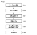
- FIG. 3 is a flowchart illustrating a processing procedure of strain measurement of sample 1 using the strain measuring device 100 according to the first embodiment.
- FIG. 4 is a diagram for explaining the sample preparation process of step S10 of FIG.
- FIG. 4 schematically shows a plan view of the holder 10, the sample 1, and the stress-stimulated luminescent material 2.
- Sample 1 is mounted on the main surface 11a of the first mounting plate 11 of the holder 10 and the main surface 12a of the second mounting plate 12.
- a deformation region is formed in the central portion of the sample 1 in the lateral direction.
- This deformed region has a strip-shaped shape extending in the vertical direction.
- the stress-stimulated luminescent material 2 is adhered to the surface of the sample 1 so as to be located at least on the deformation region of the sample 1.
- the stress-stimulated luminescent material 2 has a rectangular shape having a size similar to that of the sample 1, and is arranged so as to cover the entire surface of the sample 1.
- the stress-stimulated luminescent material 2 can be formed, for example, by attaching a stress-stimulated luminescent sheet containing a stress-stimulated luminescent material to a predetermined region of sample 1.
- the stress-stimulated luminescent material 2 is, for example, defect-controlled strontium aluminate (SrAl 2 O 4 : Eu) to which europium is added, and exhibits green light emission centered at a wavelength of 520 nm.
- the marker 3 is arranged on the surface of the holder 10 by step S20. Specifically, as shown in FIG. 4, the marker 3 is arranged on at least one of the main surface 11a of the first mounting plate 11 and the main surface 12a of the second mounting plate 12. In the example of FIG. 4, the marker 3 is arranged on the main surface 12a of the second mounting plate 12.
- Marker 3 is formed by a phosphorescent body.
- a phosphorescent body temporarily traps carriers such as electrons or holes generated by external energy (ultraviolet rays, purple light, blue light, etc.) in defects in the crystal, and the trapped carriers are gradually trapped by the thermal energy of the temperature. It shows a long-lasting luminescence by releasing to and recombining at the luminescence center.
- the phosphorescent body is also referred to as a long afterglow illuminant. Phosphorescent bodies are widely used in visibility luminous paints.
- the long afterglow means that even if the excitation light is stopped after the excitation light is irradiated, the light continues to be emitted for a long time (for example, about several minutes to several hours).
- the center wavelength (emission peak) of light emission of the phosphorescent body is generally about 480 to 700 nm (green to red).
- the center wavelength of the light emission of the phosphorescent body constituting the marker 3 is set to be different from the wavelength range of the excitation light emitted by the light source 31.
- the excitation light is ultraviolet light or blue light (wavelength range is 100 to 500 nm)
- the marker 3 uses a phosphorescent body having a center wavelength of light emission of 600 to 700 nm and exhibiting red light emission.
- the phosphorescent article showing a red light for example, Y 2 O 2 S: Ti , Mg, and the like Gd.
- the stress-stimulated luminescent material 2 is excited by the emission of the marker 3 even after the irradiation of the excitation light is stopped from the light source 31. This is because it becomes difficult to accurately measure the mechanoluminescence of the stress-stimulated luminescent material 2.
- the stress-stimulated luminescent material 2 is defect-controlled strontium aluminate (SrAl 2 O 4 : Eu) to which europium is added, the stress-stimulated luminescent material 2 emits green light.
- the marker 3 since the marker 3 emits red light, the light emission of the stress-stimulated luminescent material 2 and the light emission of the marker 3 can be clearly distinguished visually.
- the marker 3 can be formed by applying a phosphorescent paint to a predetermined region of the main surface 12a of the second mounting plate 12.
- the marker 3 can be formed by attaching a sheet made of a phosphorescent material to a predetermined region of the main surface 12a of the second mounting plate 12.
- the marker 3 can have any shape. In the example of FIG. 4, the marker 3 has a band-like shape. Further, the number of markers 3 may be singular or plural.
- the marker 3 is arranged on the surface of the movable portion of the holder 10. While the load is applied, the position of the marker 3 arranged on the movable portion changes as the sample 1 is deformed. By capturing the change in the position of the marker 3, the deformed state of the sample 1 can be acquired.
- step S30 of FIG. 3 the controller 50 irradiates the stress-stimulated luminescent material 2 and the marker 3 with excitation light from the light source 31.
- 5 (A) shows the sample 1 before the load is applied
- FIGS. 5 (B) and 5 (C) show the sample 1 under the load.
- the light source 31 irradiates excitation light (for example, ultraviolet rays).
- excitation light for example, ultraviolet rays.
- the stress-stimulated luminescent material 2 receives the excitation light and transitions to the luminescent state.
- the phosphorescent body constituting the marker 3 also receives the excitation light and transitions to the light emitting state. According to this, the stress-stimulated luminescent material 2 and the marker 3 can be excited at the same time by using a common light source 31. Even after the irradiation of the excitation light is stopped, the marker 3 continues to emit light.
- step S40 in FIG. 3 the controller 50 applies a load (bending load) to the sample 1 by driving the first driver 20 to bend the sample 1.
- a load bending load
- FIG. 5B the sample 1 is bent by rotating the drive shaft 13 in the positive direction (direction of arrow A) by the first driver 20.
- FIGS. 5B and 5C show step by step how the sample 1 is bent in conjunction with the forward rotation of the drive shaft 13. Assuming that the bending angle of the sample 1 is ⁇ , the bending angle ⁇ changes in the range of 0 ° to 90 °.
- step S50 of FIG. 3 the controller 50 takes an image of the sample 1 by the camera 40 at the timing of applying the load to the sample 1. That is, the camera 40 captures the light emission of the stress-stimulated luminescent material 2. Imaging by the camera 40 is performed in a dark room. The controller 50 can display the acquired captured image on the display 60.
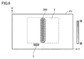
- FIG. 6 is a diagram schematically showing a captured image acquired by step S50 of FIG.
- the intensity of the emission intensity of the stress-stimulated luminescent material 2 is expressed by brightness on a two-dimensional plane.
- the intensity of the stress luminescence intensity may be expressed by at least one of chromaticity, saturation and lightness.
- the intensity of the stress luminescence intensity is drawn by different hatching for convenience. Therefore, on the right side of the captured image P1, a bar indicating the range of hatching assigned according to the intensity of the stress luminescence intensity is shown.
- the mechanoluminescent pattern 200 is vertically oriented (X-axis direction) in the central portion (that is, the central portion of bending) in the lateral direction (Y-axis direction) of the stress-stimulated luminescent material 2. Appears in the form of a strip extending to.
- This stress-stimulated luminescence pattern 200 corresponds to the deformation region of sample 1. Therefore, by extracting and analyzing the stress-stimulated luminescence pattern 200 from the captured image P1, it becomes possible to visualize and quantify the strain generated in the sample 1.
- a portion having a large stress luminescence intensity indicates a portion having a large strain
- a portion having a small stress luminescence intensity indicates a portion having a small strain. Therefore, based on the distribution of the stress-stimulated luminescence intensity, the distribution of the strain amount of the sample 1 in the bent state can be visualized and quantified.
- the emission of the marker 3 appears in the captured image P1.
- This light emission corresponds to the afterglow emitted by the phosphorescent body constituting the marker 3.
- FIGS. 5B and 5C when the first mounting plate 11 and the second mounting plate 12 are rotated, the position of the marker 3 arranged on the main surface 12a of the second mounting plate 12 is located. Change. Therefore, the position and shape of the light emission of the marker 3 appearing in the captured image P1 acquired by the camera 40 located above the main surface 12a of the second mounting plate 12 will also change.
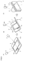
- FIG. 7 is a diagram schematically showing a change in the captured image P1 acquired in step S50 of FIG.
- FIG. 7A schematically shows the sample 1 before the load is applied and the captured image thereof.
- 7 (B) and 7 (C) schematically show the sample 1 under load and the captured image thereof.
- 7 (A) to 7 (C) show the first mounting plate 11, the second mounting plate 12, and the sample 1 attached to these as viewed from the X-axis direction.
- 7 (B) and 7 (C) show a state in which the sample 1 is bent from the state of FIG. 7 (A).
- the stress-stimulated luminescent material 2 is arranged on the surface of the sample 1, and the marker 3 is arranged on the main surface 12a of the second mounting plate 12.
- the stress-stimulated luminescent material 2 has not yet emitted light. Therefore, only the light emission of the marker 3 appears in the captured image P1. Assuming that the length of the marker 3 in the captured image P1 in the Y direction is L, the length L is the length L1 based on the length of the marker 3 in the Y direction.
- the main drive shaft 13 When the drive shaft 13 is rotated in the positive direction (clockwise direction) around the central axis of the drive shaft 13 by the first driver 20 from the state of FIG. 7 (A), as shown in FIGS. 7 (B) and 7 (C), the main drive shaft 13 is rotated.
- the sample 1 attached to the surface 12a and the main surface 11a is the main surface 12a and the main surface that rotate symmetrically with respect to the plane P about the end portion 12ac and the end portion 11ac that are parallel to each other and have a constant distance K. It is folded between 11a. Therefore, the sample 1 in any of the vicinity of the end portion 12ac, the vicinity of the end portion 11ac, and between the end portions 12ac and 11ac is bent with substantially the same bending radius.
- the load applying mechanism of FIG. 1 rotates the main surface 12a and the main surface 11a in a state where the end 12ac and the end 11ac are always parallel to the end 12ac and the end 11ac and the distance K is kept constant.
- the portion of the sample 1 located between the vicinity of the end portion 12ac and the vicinity of the end portion 11ac is deformed, but the rest of the other sample 1 is hardly deformed.
- FIG. 8 is a diagram showing the relationship between the bending angle ⁇ of the sample 1 and the length L of the marker 3 appearing in the captured image P1 in the Y direction.
- the length L of the marker 3 gradually becomes shorter from L1 to L2 as the bending angle ⁇ of the sample 1 gradually increases.
- the deformed state of the sample 1 based on the detected length L ( The bending angle ⁇ ) of the sample 1 can be known.
- the data processing unit 66 is based on the length L of the marker 3 in the captured image P1.
- the bending angle ⁇ of the sample 1 can be obtained.
- step S60 by extracting the stress-stimulated luminescence pattern 200 that appears in the captured image P1 for each bending angle ⁇ , the distribution of the stress-stimulated luminescence intensity shown by the stress-stimulated luminescence pattern 200 can be associated with the deformed state of the sample 1. .. According to this, it is possible to verify what kind of deformation state (bending angle ⁇ ) the sample 1 is in when the strain is generated in the sample 1. In addition, it is possible to evaluate the correlation between the time-series change in the distribution of stress-stimulated luminescence intensity and the time-series change in the deformation state of sample 1.
- the stress-stimulated luminescent material 2 is arranged on the surface of the sample 1 and the surface of the holder 10 supporting the sample 1 has a phosphorescent property.
- the marker 3 having the marker 3 the deformed state of the sample 1 can be acquired based on the luminescence of the marker 3 at the time of measuring the stress luminescence in a dark place.
- FIG. 9 is a diagram for explaining the process of arranging the marker in step S20 of FIG.
- FIG. 9 schematically shows a plan view of the holder 10, the sample 1, the stress-stimulated luminescent material 2, and the marker 3.
- FIG. 9 differs from FIG. 4 only in the configuration of the marker 3.
- a plurality of markers 3 are arranged on the main surface 11a of the first mounting plate 11 of the holder 10 and the main surface 12a of the second mounting plate 12.
- the plurality of markers 3 are arranged on the outer peripheral portion of the sample 1.
- four markers 3 are arranged at the four corners of the rectangular sample 1.
- the four markers 3 are formed by a phosphorescent body. As described in the first embodiment, the central wavelength of light emission of the phosphorescent body constituting each marker 3 is different from the wavelength range of the excitation light irradiated by the light source 31. Further, the stress luminescent material 2 and the marker 3 have different emission colors.
- the four markers 3 can be formed by applying a phosphorescent paint to predetermined areas of the main surface 11a of the first mounting plate 11 and the main surface 12a of the second mounting plate 12.
- the four markers 3 can be formed by attaching a sheet made of a phosphorescent material to predetermined regions of the main surface 11a of the first mounting plate 11 and the main surface 12a of the second mounting plate 12.
- the marker 3 can have any shape. In the example of FIG. 9, the marker 3 has an L-shape.
- the region where the marker 3 is arranged may be the surface of the holder 10 that supports the sample 1 and may be the outer peripheral portion of the sample 1.
- the number of markers 3 is not limited to four.
- step S30 of FIG. 3 the controller 50 irradiates the stress-stimulated luminescent material 2 and the four markers 3 with excitation light from the light source 31. Both the stress-stimulated luminescent material 2 and the four markers 3 receive the excitation light and transition to the luminescent state.
- step S40 the controller 50 applies a bending load to the sample 1 by driving the first driver 20 to bend the sample 1.
- the controller 50 takes an image of the sample 1 by the camera 40 at the timing of applying the load to the sample 1.
- the controller 50 can display the acquired captured image on the display 60.
- FIG. 10 schematically shows a change in the captured image acquired by step S50 in FIG.
- FIG. 10A shows the sample 1 before the load is applied and the captured image thereof.
- 10 (B) and 10 (C) show the sample 1 under load and the captured image thereof.
- the stress-stimulated luminescent material 2 has not yet emitted light. Therefore, only the light emission (afterglow) of the four markers 3 appears in the captured image P1.
- the emission positions of the four markers 3 in the captured image P1 correspond to the positions of the four corners of the rectangular sample 1.
- the positions of the four markers 3 in the captured image P1 represent the positions of the four corners of the sample 1, respectively. Therefore, since the shape of the sample 1 can be estimated based on the positions of the four markers 3 in the captured image P1, the deformed state of the sample 1 can be acquired. As a result, as in the first embodiment, by extracting the stress-stimulated luminescence pattern 200 appearing in the captured image P1, the distribution of the stress-stimulated luminescence intensity shown by the stress-stimulated luminescence pattern 200 can be associated with the deformed state of the sample 1. can.
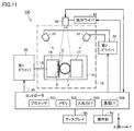
- FIG. 11 is a block diagram showing the overall configuration of the strain measuring device according to the third embodiment.
- the strain measuring device 100 according to the third embodiment has a different configuration of the load applying mechanism as compared with the strain measuring device 100 shown in FIG. The description of the parts common to the strain measuring device 100 shown in FIG. 1 will not be repeated.
- the load application mechanism is configured to apply a compressive load to sample 1.
- the load applying mechanism includes a holder 10 and a first driver 20.
- sample 1 is a flat plate member having a circular shape.
- a stress-stimulated luminescent material 2 is arranged on the surface of the sample 1.
- the stress-stimulated luminescent material 2 is arranged on the surface of at least a predetermined region of the sample 1. This predetermined region is set to include a region where stress is generated when a compressive load is applied to the sample 1 (that is, a deformation region of the sample 1). Therefore, the stress-stimulated luminescent material 2 is compressed integrally with the sample 1 to cause deformation (strain).
- the holder 10 has a first support member 16, a second support member 17, and a drive shaft 18.
- the first support member 16 and the second support member 17 have a columnar shape, and their ends in the longitudinal direction are arranged so as to face each other along the Y direction.
- a drive shaft 18 is connected to the first support member 16.
- the base of the drive shaft 18 is attached to the first driver 20.
- the first driver 20 is configured to be able to slide the first support member 16 in the Y direction by sliding the drive shaft 18 in the Y direction.
- the second support member 17 is fixed.
- the first support member 16 corresponds to one embodiment of the "movable portion"
- the second support member 17 corresponds to one embodiment of the "fixed portion”.
- both ends in the Y direction are supported by the first support member 16 and the second support member 17.
- a compressive load is applied to the sample 1.
- the camera 40 is arranged so as to include the stress-stimulated luminescent material 2 and the marker 3 located on the predetermined region of the sample 1 in the imaging field of view.
- the processing procedure for measuring the strain of the sample 1 using the strain measuring device 100 according to the third embodiment is basically the same as the flowchart shown in FIG. 3 except for the processing (S20) for arranging the markers.
- sample 1 is prepared by step S10 in FIG.
- the sample 1 is attached between the first support member 16 and the second support member 17 of the holder 10.
- the stress-stimulated luminescent material 2 is adhered to the surface of the sample 1.
- the stress-stimulated luminescent material 2 has a circular shape having a size similar to that of the sample 1, and is arranged so as to cover the entire surface of the sample 1.
- the marker 3 is placed on the holder 10 by step S20 in FIG. Specifically, the marker 3 is arranged on at least one surface of the first support member 16 and the second support member 17. In the example of FIG. 11, the marker 3 is arranged on the surface of the first support member 16.
- the marker 3 can be formed by applying a phosphorescent paint to a predetermined region on the surface of the first support member 16.
- the marker 3 can be formed by attaching a sheet made of a phosphorescent material to a predetermined region on the surface of the first support member 16.
- the marker 3 is formed by a phosphorescent body and constitutes a scale. This scale can be used as an index for measuring the size of the sample 1 in the Z direction. In order to serve as an index, the marker 3 is arranged in a region where the shape of the captured image P1 does not change when a load is applied. The marker 3 may be arranged on the surface of the second support member 17.
- step S30 of FIG. 3 the controller 50 irradiates the stress-stimulated luminescent material 2 and the marker 3 with excitation light from the light source 31. Both the stress luminescent material 2 and the marker 3 receive the excitation light and transition to the light emitting state. Even after the irradiation of the excitation light is stopped, the marker 3 continues to emit light.
- step S40 in FIG. 3 the controller 50 drives the first driver 20 to apply a load to the sample 1.
- a compressive load is applied to the sample 1 by sliding the first support member 16 in the Y direction by the first driver 20.
- step S50 of FIG. 3 the controller 50 takes an image of the sample 1 by the camera 40 at the timing of applying the load to the sample 1.
- the camera 40 captures the light emission of the stress-stimulated luminescent material 2 and the light emission of the marker 3.
- the controller 50 can display the image captured by the camera 40 on the display 60.
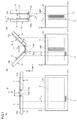
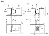
- FIG. 12 is a diagram schematically showing changes in the captured image P1 acquired in step S50 of FIG.
- FIG. 12A schematically shows the sample 1 before the load is applied and the captured image thereof.
- FIG. 12B schematically shows the sample 1 under load and the captured image thereof.
- FIG. 12 (A) and 12 (B) show the first support member 16, the second support member 17, and the sample 1 attached to them as viewed from the X-axis direction.
- FIG. 12B shows a state in which a compressive load is applied to the sample 1 from the state of FIG. 12A.
- the stress-stimulated luminescent material 2 is arranged on the surface of the sample 1
- the marker 3 is arranged on the surface of the first support member 16.
- the stress-stimulated luminescent material 2 has not yet emitted light when a compressive load is not applied to the sample 1. Therefore, only the light emission of the marker 3 appears in the captured image P1.
- the sample 1 is compressed and deformed in the Y direction as shown in FIG. 12 (B). Therefore, the light emission of the stress-stimulated luminescent material 2 and the light emission of the marker 3 appear in the captured image P1.
- the length of the sample 1 in the Y direction decreases from the initial value Y1 to Y2.
- the length of the sample 1 in the Z direction increases from the initial value Z1 to Z2.
- the amount of deformation of the sample 1 in the Y direction due to the compressive load can be obtained from the amount of displacement of the first support member 16 in the Y direction.
- the amount of deformation of the sample 1 in the Z direction can be obtained by using the scale indicated by the marker 3 in the captured image P1. According to this, it is possible to acquire the deformed state of the sample 1 due to the compressive load.
- the distribution of the stress-stimulated luminescence intensity shown by the stress-stimulated luminescence pattern 200 is associated with the deformed state of the sample 1. Can be done.
- the strain measuring device measures the strain of the sample.
- a stress-stimulated luminescent material is arranged at least in a predetermined area on the surface of the sample.
- the strain measuring device includes a holder that supports the sample, a load application mechanism that applies a load to the sample by operating the holder, a luminous marker placed on the surface of the holder, and a stress-stimulated luminescent material and a marker. It comprises a light source configured to irradiate the excitation light and a camera configured to image the light emitted by the stress-stimulated luminescent material when a load is applied and the light emitted by the marker.
- the stress-stimulated luminescent material is placed on the surface of the sample, and the mechanoluminescent marker is placed on the surface of the holder supporting the sample to emit stress in a dark place.
- the deformation state of the sample can be obtained based on the emission of the marker.
- the marker is composed of a phosphorescent body.
- the phosphorescent body is configured such that the wavelength of emission is different from the wavelength of excitation light.
- the excitation light is ultraviolet light or blue light.
- the marker is composed of a phosphorescent body that emits red light.
- the phosphorescent body is further configured such that the wavelength of light emission is different from the wavelength of light emission of the stress-stimulated luminescent material.
- the holder includes a fixed portion and a movable portion, and a load is applied to the sample by the relative movement of the movable portion with respect to the fixed portion. It is configured as follows. The marker is placed on the movable part of the holder.
- the position and / or shape of the marker appearing in the captured image changes according to the movement of the moving part.
- the deformed state of the sample can be acquired based on the change in the marker.
- the marker is arranged on the outer peripheral portion of the sample on the surface of the holder.
- the shape of the sample can be estimated based on the position of the marker appearing in the captured image, the deformed state of the sample can be acquired.
- the marker includes a scale for measuring the size of the sample.
- the amount of deformation of the sample can be measured using the scale indicated by the marker in the captured image.
- the strain measuring method is a strain measuring method for measuring the strain of a sample, in which a step of arranging a stress-stimulated luminescent material in at least a predetermined region on the surface of the sample and a holder for supporting the sample are provided.
- stress mechanoluminescence in a dark place is performed by arranging a stress-stimulated luminescent material on the surface of the sample and arranging a marker having a phosphorescent property on the surface of a holder supporting the sample.
- the deformation state of the sample can be obtained based on the emission of the marker.
- the strain measuring method according to paragraph 8 further includes a step of measuring the deformation state of the sample based on the light emission of the marker in the captured image acquired in the step of imaging.
- the holder includes a fixed portion and a movable portion.
- the step of applying the load includes a step of applying a load to the sample by moving the movable part relative to the fixed part.
- the step of placing the marker includes a step of placing the marker on the movable part of the holder.
- the position and / or shape of the marker appearing in the captured image changes according to the movement of the moving part.
- the deformed state of the sample can be acquired based on the change in the marker.
- the step of arranging the marker includes the step of arranging the marker on the outer peripheral portion of the sample on the surface of the holder.
- the shape of the sample can be estimated based on the position of the marker appearing in the captured image, the deformed state of the sample can be acquired.
- the step of arranging the marker includes the step of arranging the scale for measuring the size of the sample.
- the amount of deformation of the sample can be measured using the scale indicated by the marker in the captured image.
- the step of irradiating the excitation light includes a step of simultaneously irradiating the stress-stimulated luminescent material and the marker with the excitation light using a common light source.
- the configuration of the strain measuring device can be simplified and the strain measuring process can be simplified.
Landscapes
- Physics & Mathematics (AREA)
- General Physics & Mathematics (AREA)
- Health & Medical Sciences (AREA)
- Life Sciences & Earth Sciences (AREA)
- Chemical & Material Sciences (AREA)
- Analytical Chemistry (AREA)
- Biochemistry (AREA)
- General Health & Medical Sciences (AREA)
- Immunology (AREA)
- Pathology (AREA)
- Investigating Strength Of Materials By Application Of Mechanical Stress (AREA)
Priority Applications (1)
| Application Number | Priority Date | Filing Date | Title |
|---|---|---|---|
| JP2022522547A JP7332044B2 (ja) | 2020-05-15 | 2021-03-26 | ひずみ計測装置およびひずみ計測方法 |
Applications Claiming Priority (2)
| Application Number | Priority Date | Filing Date | Title |
|---|---|---|---|
| JP2020085770 | 2020-05-15 | ||
| JP2020-085770 | 2020-05-15 |
Publications (1)
| Publication Number | Publication Date |
|---|---|
| WO2021229929A1 true WO2021229929A1 (ja) | 2021-11-18 |
Family
ID=78525659
Family Applications (1)
| Application Number | Title | Priority Date | Filing Date |
|---|---|---|---|
| PCT/JP2021/012814 Ceased WO2021229929A1 (ja) | 2020-05-15 | 2021-03-26 | ひずみ計測装置およびひずみ計測方法 |
Country Status (2)
| Country | Link |
|---|---|
| JP (1) | JP7332044B2 (https=) |
| WO (1) | WO2021229929A1 (https=) |
Citations (5)
| Publication number | Priority date | Publication date | Assignee | Title |
|---|---|---|---|---|
| JPS5923649U (ja) * | 1982-08-05 | 1984-02-14 | 大起理化工業株式会社 | 土壌抵抗測定器 |
| US20150103333A1 (en) * | 2013-10-10 | 2015-04-16 | GunJin Yun | Apparatus for quantitative measurements of stress distributions from mechanoluminescence materials |
| JP2017129530A (ja) * | 2016-01-22 | 2017-07-27 | 日本碍子株式会社 | 変位検出器及び変位の検出方法 |
| JP2018163083A (ja) * | 2017-03-27 | 2018-10-18 | 株式会社トヨタプロダクションエンジニアリング | 歪み測定装置、歪み測定方法及び歪み測定プログラム |
| JP2020034466A (ja) * | 2018-08-31 | 2020-03-05 | 株式会社トヨタプロダクションエンジニアリング | 応力発光計測装置及び応力発光計測方法 |
-
2021
- 2021-03-26 WO PCT/JP2021/012814 patent/WO2021229929A1/ja not_active Ceased
- 2021-03-26 JP JP2022522547A patent/JP7332044B2/ja active Active
Patent Citations (5)
| Publication number | Priority date | Publication date | Assignee | Title |
|---|---|---|---|---|
| JPS5923649U (ja) * | 1982-08-05 | 1984-02-14 | 大起理化工業株式会社 | 土壌抵抗測定器 |
| US20150103333A1 (en) * | 2013-10-10 | 2015-04-16 | GunJin Yun | Apparatus for quantitative measurements of stress distributions from mechanoluminescence materials |
| JP2017129530A (ja) * | 2016-01-22 | 2017-07-27 | 日本碍子株式会社 | 変位検出器及び変位の検出方法 |
| JP2018163083A (ja) * | 2017-03-27 | 2018-10-18 | 株式会社トヨタプロダクションエンジニアリング | 歪み測定装置、歪み測定方法及び歪み測定プログラム |
| JP2020034466A (ja) * | 2018-08-31 | 2020-03-05 | 株式会社トヨタプロダクションエンジニアリング | 応力発光計測装置及び応力発光計測方法 |
Also Published As
| Publication number | Publication date |
|---|---|
| JPWO2021229929A1 (https=) | 2021-11-18 |
| JP7332044B2 (ja) | 2023-08-23 |
Similar Documents
| Publication | Publication Date | Title |
|---|---|---|
| JP2021179354A (ja) | 応力発光測定装置および応力発光測定方法 | |
| US11704786B2 (en) | Stress luminescence measurement method and stress luminescence measurement device | |
| JP5313711B2 (ja) | 光学式測定装置 | |
| CN116222846A (zh) | 应力测量方法、装置以及计算机可读非暂时性存储介质 | |
| JP7332044B2 (ja) | ひずみ計測装置およびひずみ計測方法 | |
| US20210372868A1 (en) | Stress management device | |
| JP2006250656A (ja) | 発光素子アレイの照度むら測定方法及び装置 | |
| US20230417678A1 (en) | Method of producing stress-luminescent material, method of producing stress-luminescent body, strain measurement method, stress-luminescent body, stress-luminescent coating material, and device for producing stress-luminescent body | |
| KR20230060930A (ko) | 전지 검사 장치 | |
| CN113973159A (zh) | 图像扫描系统和扫描方法 | |
| WO2021240947A1 (ja) | 応力測定装置 | |
| JP2022061564A (ja) | 接着剤の接着強さ試験方法、接着剤の接着強さ試験装置および接着剤の接着強さ試験システム | |
| JP5203172B2 (ja) | ひずみゲージ | |
| US12035895B2 (en) | Geometric light source apparatus with dimming features for endoscope | |
| JP7099634B2 (ja) | 応力発光測定装置、応力発光測定方法および応力発光測定システム | |
| WO2020230473A1 (ja) | 応力発光測定装置、応力発光測定方法および応力発光測定システム | |
| WO2021157656A1 (ja) | フレキシブルディスプレイ搭載製品の検査方法、フレキシブルディスプレイ搭載製品の製造方法、フレキシブルディスプレイ搭載製品の検査システムおよびフレキシブルディスプレイ搭載製品 | |
| WO2025126686A1 (ja) | 応力発光計測装置および応力発光計測方法 | |
| WO2022003848A1 (ja) | 検査方法、検査システムおよび応力発光測定装置 | |
| WO2018230318A1 (ja) | スケール、撮像装置、撮像システム、キット、および撮像装置の調整方法 | |
| JP2023176372A (ja) | 応力発光計測方法および応力発光計測システム | |
| JP2021004752A (ja) | 応力発光測定装置、応力発光測定方法および応力発光測定システム | |
| JP2024509762A (ja) | ディスプレイ製造における基板を検査するための装置及び方法並びに基板を処理するためのシステム | |
| JP2021004753A (ja) | 応力発光測定装置、応力発光測定方法および応力発光測定システム | |
| JP2024011291A (ja) | 試験用シート、試験用シートの製造方法および計測方法 |
Legal Events
| Date | Code | Title | Description |
|---|---|---|---|
| 121 | Ep: the epo has been informed by wipo that ep was designated in this application |
Ref document number: 21803010 Country of ref document: EP Kind code of ref document: A1 |
|
| ENP | Entry into the national phase |
Ref document number: 2022522547 Country of ref document: JP Kind code of ref document: A |
|
| NENP | Non-entry into the national phase |
Ref country code: DE |
|
| 122 | Ep: pct application non-entry in european phase |
Ref document number: 21803010 Country of ref document: EP Kind code of ref document: A1 |