WO2021229724A1 - 統合装置、データテーブル統合方法、プログラム - Google Patents
統合装置、データテーブル統合方法、プログラム Download PDFInfo
- Publication number
- WO2021229724A1 WO2021229724A1 PCT/JP2020/019121 JP2020019121W WO2021229724A1 WO 2021229724 A1 WO2021229724 A1 WO 2021229724A1 JP 2020019121 W JP2020019121 W JP 2020019121W WO 2021229724 A1 WO2021229724 A1 WO 2021229724A1
- Authority
- WO
- WIPO (PCT)
- Prior art keywords
- row
- data
- data table
- limit position
- ascending sort
- Prior art date
- Legal status (The legal status is an assumption and is not a legal conclusion. Google has not performed a legal analysis and makes no representation as to the accuracy of the status listed.)
- Ceased
Links
Images


Classifications
-
- G—PHYSICS
- G06—COMPUTING OR CALCULATING; COUNTING
- G06F—ELECTRIC DIGITAL DATA PROCESSING
- G06F16/00—Information retrieval; Database structures therefor; File system structures therefor
- G06F16/20—Information retrieval; Database structures therefor; File system structures therefor of structured data, e.g. relational data
- G06F16/22—Indexing; Data structures therefor; Storage structures
- G06F16/2282—Tablespace storage structures; Management thereof
-
- G—PHYSICS
- G06—COMPUTING OR CALCULATING; COUNTING
- G06F—ELECTRIC DIGITAL DATA PROCESSING
- G06F16/00—Information retrieval; Database structures therefor; File system structures therefor
- G06F16/20—Information retrieval; Database structures therefor; File system structures therefor of structured data, e.g. relational data
- G06F16/21—Design, administration or maintenance of databases
- G06F16/211—Schema design and management
- G06F16/213—Schema design and management with details for schema evolution support
-
- G—PHYSICS
- G06—COMPUTING OR CALCULATING; COUNTING
- G06F—ELECTRIC DIGITAL DATA PROCESSING
- G06F7/00—Methods or arrangements for processing data by operating upon the order or content of the data handled
- G06F7/06—Arrangements for sorting, selecting, merging, or comparing data on individual record carriers
- G06F7/08—Sorting, i.e. grouping record carriers in numerical or other ordered sequence according to the classification of at least some of the information they carry
Definitions
- the present invention relates to an integrated device, a data table integration method, and a program.
- Patent Document 1 discloses a technique of performing an outer join (outer join) process to generate a new output table.
- each of the data elements of the first data table of the two data tables containing at least the data elements that can be compared in magnitude as information in one row unique?
- the data element of each row of the second data table of the two data tables and each row of the first data table are unique.
- the magnitude of each row after ascending sort using the data elements of is compared with the data element of each row, and the row of the second data table is the most of the first data table after the ascending sort so as to match the ascending sort.
- the position specifying means for specifying the lower limit position that can be added to the lower row, the data element of the row of the second data table, and the said in the first data table after the ascending order specified by using the data element of the row.
- the integration target row indicating those data elements is specified in the second data table and the first data table, and at least those first.
- each of the data elements of the first data table of the two data tables including at least the data elements that can be compared in magnitude as information in one row is unique. If each of the data elements is unique in the array of data elements of the first data table, the data element of each row of the second data table of the two data tables and the first data element are present. A magnitude comparison is made with the data elements of each row after ascending sort using the data elements of each row of the data table, and each row of the first data table after the ascending sort of the data elements of each row of the second data table is performed.
- the lower limit position in the array of data elements of the above is specified, and the data element of the row of the second data table and the lower limit position specified by using the data element of the row are the first data table after the ascending order sorting.
- the rows to be integrated that match the data elements of the row with the lower limit position in the array of are specified in the second data table and the first data table, and at least those second data table and the first data table are specified. Generate an integrated data table that integrates the above-mentioned integration target rows with.
- the program uses the computer of the integrated device as the data element of the first data table of the two data tables containing at least the data elements that can be compared in magnitude as information in one row.
- a unique determination means for determining whether is unique, and when each of the data elements is unique in the array of data elements of the first data table, each row of the second data table of the two data tables The magnitude comparison between the data element and the data element of each row after ascending order using the data element of each row of the first data table is performed, and the data element of each row of the second data table is compared with each other after the ascending order sorting.
- the position specifying means for specifying the lower limit position in the array of the data elements of each row of the first data table, the data element of the row of the second data table, and the lower limit position specified by using the data element of the row.
- the rows to be integrated that match the data elements of the row having the lower limit position in the array of the first data table after ascending order are specified in the second data table and the first data table, and at least those first.
- the amount of processing can be reduced in the generation of the integrated data table.
- FIG. 1 It is a figure which shows the structure of the information processing system provided with the integrated apparatus by this embodiment. It is a figure which shows the hardware configuration of the integrated apparatus by this embodiment. It is a functional block diagram of the integrated apparatus by this embodiment. It is a figure which shows the generation example of the integrated data table by this embodiment. It is the first figure which shows the example of the two data tables of the integration target by this embodiment. It is a figure which shows the processing flow of the integrated apparatus by this embodiment. It is the first figure which shows the processing outline of the integrated apparatus by this embodiment. It is a second figure which shows the example of the two data tables of the integration target by this embodiment. It is the 2nd figure which shows the processing outline of the integrated apparatus by this embodiment. It is a figure which shows the minimum structure of the integrated apparatus by this embodiment. It is a figure which shows the processing flow of the integrated apparatus by the minimum configuration by this embodiment.
- FIG. 1 is a diagram showing a configuration of an information processing system including an integrated device according to the same embodiment.
- the information processing system 100 may be configured by connecting the integrated device 1 and the terminal 2 by a communication network.
- the integrated device 1 generates an integrated data table in which at least two data tables stored in the own device or the like in advance are integrated into one data table.
- the terminal 2 is used by the user who operates the integrated device 1.
- the integrated device 1 and the terminal 2 are computers, respectively.
- FIG. 2 is a diagram showing a hardware configuration of the integrated device.
- the integrated device 1 includes hardware such as a CPU (Central Processing Unit) 101, a ROM (Read Only Memory) 102, a RAM (Random Access Memory) 103, a database 104, and a communication module 105. It's a computer.
- the terminal 2 is also a computer equipped with similar hardware.
- FIG. 3 is a functional block diagram of the integrated device.
- the integrated device 1 executes an integrated data table generation program. As a result, the integrated device 1 exerts the functions of the control unit 11, the sort unit 12, the unique determination unit 13, the position specifying unit 14, and the integrated unit 15.
- the control unit 11 controls each functional unit of the integrated device 1.
- the sorting unit 12 sorts each row of the data table including at least data elements that can be compared in magnitude as information of one row, based on the data elements included in the row.
- the unique determination unit 13 determines whether each of the data elements of the first data table of the two data tables including at least the data elements that can be compared in magnitude is unique as the information in one row.
- the position specifying unit 14 uses the data element of each row of the second data table and the data element of each row of the first data table of the two data tables. Compare the magnitude with the data element of each row after ascending order sorting. The position specifying unit 14 performs a magnitude comparison thereof and identifies a lower limit position where a row of the second data table can be added to the bottom row of the first data table after the ascending sort so as to match the ascending sort.
- the integration unit 15 matches the data element of the row of the second data table with the data element of the next row in the ascending sort of the lower limit position in the first data table after the ascending sort specified by using the data element of the row.
- the rows to be integrated indicating those data elements are specified in the second data table and the first data table.
- the integration unit 15 generates an integrated data table that integrates at least the rows to be integrated with the second data table and the first data table.
- FIG. 4 is a diagram showing an example of generating an integrated data table.
- an example of generating an integrated data table 43 in which two data tables of the purchase history table 41 and the purchaser table 42 are integrated is shown.
- the two data tables, the purchase history table 41 and the purchaser table 42 each include a purchaser ID as a data element that can be compared in size as a data element of each row.
- the purchase history table 41 can be regarded as the first data table of the two data tables, and the purchaser table 42 can be regarded as the second data table of the two data tables.
- the purchaser table 42 may be regarded as the first data table of the two data tables, and the purchase history table 41 may be regarded as the second data table of the two data tables.
- the purchase history table 41 is a data table in which the purchaser ID, the name (product name) of the product purchased by the purchaser indicated by the purchaser ID, the price of the product, and the date indicating the purchase date are linked.
- the purchaser table 42 is a data table in which the purchaser ID, the name of the purchaser of the purchaser ID, and the age are associated with each other. By integrating these two data tables based on the purchaser ID, it is possible to generate an integrated data table 43 in which the purchaser ID, product name, price, date, name, and age are linked.
- the integrated data table 43 does not integrate the rows including the purchaser ID; 2, name; Hanako, age; 45 included in the purchaser table 42.
- the information of the person indicated by the purchaser ID; 2, the name; Hanako, and the age; 45 may be integrated. In this case, the information may not be included in the column of the product name, price, and date as the information of the person (Null).
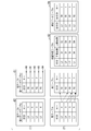
- FIG. 5 is a first diagram showing an example of two data tables to be integrated.
- FIG. 5 shows two data tables to be integrated according to the present embodiment, a right table 51 (first data table) and a left table 52 (second data table).
- Each of the right table 51 and the left table 52 has a plurality of rows in which the row ID and the key are associated with each other.
- the two data tables, the right table 51 and the left table 52 each include a key as a data element that can be compared in size as a data element of each row.
- FIG. 6 is a diagram showing a processing flow of the integrated device.
- FIG. 7 is a first diagram showing an outline of processing of the integrated device.
- the user operates the terminal 2 to access the integrated device 1.
- the user operates the terminal 2 to specify two data tables to be integrated, specify data elements that can be compared in size in those data tables, and give an instruction to start integration to the integration device 1.
- the integration device 1 starts the integration processing of the two data tables (step S101).
- the two data tables are the right table 51 (first data table) and the left table 52 (second data table) shown in FIG.
- the types of data elements that can be compared in size in the two data tables are the same.
- the key is a data element whose magnitude can be compared.
- the key information in the two data tables is the same type of information.
- the control unit 10 of the integration device 1 When the control unit 10 of the integration device 1 receives the instruction to start integration, the control unit 10 instructs the sorting unit 12 to sort the data elements in ascending order that can be compared in magnitude.
- the sorting unit 12 sorts each row of the right table and the left table in ascending order using the key (step S102). As a result, as shown in FIG. 7 (1), the sort unit 12 arranges the right table 51 so that the keys in each row of the right table 51 are "1", "2", "3", and "6" in order from the top. Sort each line in ascending order. Further, as shown in FIG. 7 (1), the sort unit 12 sets the left table 52 so that the keys in each row of the left table 52 are "1", "3", "3", and "5" in order from the top. Rearranges.
- the control unit 10 instructs the unique determination unit 13 to process.
- the unique determination unit 13 determines whether each key as a data element capable of comparing the magnitude of each row in the right table 51 is unique (step S103).
- the unique determination unit 13 outputs the determination result to the control unit 10.
- the control unit 10 defines the right table 51 as the first data table and the left table 52 as the second data table as they are. Start the integration processing of the following data tables by the processing load reduction method.
- the unique determination unit 13 determines whether the key as a data element capable of comparing the magnitude of each row in the right table 51 is unique. (Step S104).
- the unique determination unit 13 outputs the determination result to the control unit 10.
- the control unit 10 reversely replaces the definitions of the first data table and the second data table of the right table 51 and the left table 52.
- the left table 52 is defined as the first data table
- the right table 51 is defined as the second data table, and the integration processing of the following data tables by the processing load reduction method is started.
- the key as a data element that can compare the size of each row in the left table 52 is not unique. That is, there are two rows having the key "3" in the left table 52. Therefore, the description of the case where the right table 51 is defined as the first data table and the left table 52 is defined as the second data table and the following data table integration processing by the processing load reducing method is started will be continued.
- the key as a data element capable of comparing the magnitude of each row in the right table 51 is not unique, and the key as a data element capable of comparing the magnitude of each row in the left table 52 is also not unique.
- the determination result is output to the control unit 10.
- the control unit 10 determines that if the key as a data element capable of comparing the magnitude of each row is not unique in any of the data tables, the data table is switched to the integrated processing in which the processing load cannot be reduced (step S105).
- the sorting unit 12 sorts the keys as data elements that can be compared in size in each row in the data tables of both the right table 51 and the left table 52 in ascending order, but at least the size comparison is performed.
- a data table in which each key as a data element that can be created is unique may be sorted.
- the control unit 10 When the control unit 10 starts the data table integration process by the processing load reduction method, the control unit 10 outputs the data table integration process by the processing load reduction method to the position specifying unit 14.
- the position specifying unit 14 acquires the key “1” on the L3 line.
- the position specifying unit 14 compares the size of the key "1" which is the data element of the row L3 of the left table 52 with the key of each row after ascending sort using the key which is the data element of each row of the right table 51.
- the lower limit position where the L3 row of the left table 52 can be added to the bottom row of the right table 51 after the ascending sort is specified so as to fit the ascending sort.
- the spaces between the rows in the right table 51 are referred to as boundary positions B0 to B4, respectively.
- Ascending sort is performed by comparing the size of the key "1" which is the data element of the row L3 of the left table 52 and the data element of each row after ascending sort using the key which is the data element of each row of the right table 51.
- the lower limit position where the L3 row of the left table 52 can be added to the bottom row of the right table 51 after ascending sort so as to conform to is the boundary position B0. That is, in this case, the lower limit position is B0.
- the position specifying unit 14 acquires the key “3” on the L0 line.
- the position specifying unit 14 compares the size of the key "3" which is the data element of the row L0 of the left table 52 with the key of each row after ascending sort using the key which is the data element of each row of the right table 51.
- the lower limit position where the L0 row of the left table 52 can be added to the bottom row of the right table 51 after the ascending sort is specified so as to fit the ascending sort.
- Ascending sort is performed by comparing the size of the key "3" which is the data element of the row L0 of the left table 52 and the data element of each row after ascending sort using the key which is the data element of each row of the right table 51.
- the lower limit position where the L0 row of the left table 52 can be added to the bottom row of the right table 51 after ascending sort so as to conform to is the boundary position B2. That is, in this case, the lower limit position is B2.
- the position specifying unit 14 acquires the key “3” on the L2 line.
- the position specifying unit 14 compares the size of the key "3" which is the data element of the row L2 of the left table 52 with the key of each row after ascending sort using the key which is the data element of each row of the right table 51.
- the lower limit position where the L2 row of the left table 52 can be added to the bottom row of the right table 51 after the ascending sort is specified so as to fit the ascending sort.
- Ascending sort is performed by comparing the size of the key "3" which is the data element of the row L2 of the left table 52 and the data element of each row after ascending sort using the key which is the data element of each row of the right table 51.
- the lower limit position where the L2 row of the left table 52 can be added to the bottom row of the right table 51 after ascending sort so as to conform to is the boundary position B2. That is, in this case, the lower limit position is B2.
- the position specifying unit 14 acquires the key “5” of the L1 line.
- the position specifying unit 14 compares the size of the key "5", which is the data element of the row L1 of the left table 52, with the key of each row after ascending sort using the key which is the data element of each row of the right table 51.
- the lower limit position where the L1 row of the left table 52 can be added to the bottom row of the right table 51 after the ascending sort is specified so as to fit the ascending sort.
- Ascending sort is performed by comparing the size of the key "5" which is the data element of the row L1 of the left table 52 and the data element of each row after ascending sort using the key which is the data element of each row of the right table 51.
- the lower limit position where the L1 row of the left table 52 can be added to the bottom row of the right table 51 after ascending sort so as to conform to is the boundary position B3. That is, in this case, the lower limit position is B3.
- the position specifying unit 14 specifies the lower limit position where the L3 row of the left table 52 can be added to the bottom row of the right table 51 after ascending sort as B0. Further, the position specifying unit 14 specifies the lower limit position where the L0 row of the left table 52 can be added to the bottom row of the right table 51 after sorting in ascending order as B2. Further, the position specifying unit 14 specifies the lower limit position where the L2 row of the left table 52 can be added to the bottom row of the right table 51 after sorting in ascending order as B2. Further, the position specifying unit 14 specifies the lower limit position where the L1 row of the left table 52 can be added to the bottom row of the right table 51 after sorting in ascending order as B3.
- the position specifying unit 14 specifies the lower limit position that can be added to the bottom row of the right table 51 after ascending sort for all the rows of the left table 52 (step S106). Then, the position specifying unit 14 generates a position specifying table 53 in which the row ID of the left table 52 and the lower limit position specified for the row ID are associated with each other. Then, the position specifying unit 14 outputs the processing end to the control unit 10.
- the processing of the position specifying unit 14 is the data element of each row of the second data table (left table 52) of the two data tables when each data element of the first data table (right table 51) is unique. And the data element of each row of the first data table (right table 51) are used to compare the magnitude with the data element of each row after ascending sort, and the second data table (left table 52) is adapted to the ascending sort.
- This is one aspect of the process of specifying the lower limit position where the row can be added to the bottom row of the first data table (right table 51) after ascending order sorting.
- the above-mentioned magnitude comparison is performed using a binary search. Alternatively, other search methods may be used for magnitude comparison. For example, the magnitude comparison may be performed by a simple search. Since the magnitude comparison is performed after ascending sorting of the keys that are data elements, the processing amount and processing load can be reduced by performing a binary search.
- the control unit 10 instructs the integration unit 15 to integrate the two data tables.
- the integration unit 15 identifies the row L3 and the row R1 as the integration target rows, and integrates the row L3 and the row R1 into the row ID “L3”, the row ID “R1”, and the key “1”. Generate an integrated data table to include in.
- the integration unit 15 specifies whether all the rows in the left table 52 are the same integration target rows, and integrates the rows in the left table 52 identified as the integration target rows and the rows in the right table 51. And merge it into the integrated data table. As a result, an integrated data table is generated (step S107).
- control unit 10 determines in step S105 to switch to the data table integration process whose processing load cannot be reduced, the control unit 10 outputs the data table integration process to the position specifying unit 14.
- FIG. 8 is a second diagram showing an example of two data tables to be integrated.
- the right table 61 first data table
- the left table 62 second data table
- Each of the right table 61 and the left table 62 has a plurality of rows in which the row ID and the key are associated with each other.
- the key as a data element capable of comparing the magnitude of each row in the data table is not unique.
- there are two rows having the key "1”, and the keys as data elements that can be compared in size of each row are not unique.
- the left table 62 there are two rows having the key "3", and the key as a data element capable of comparing the magnitude of each row is not unique. In this way, if the key as a data element that can compare the size of each row is not unique in any of the data tables, the following data table integration processing is performed.
- FIG. 9 is a second diagram showing an outline of processing of the integrated device.
- the keys of each row of the right table 61 are "1", “1", and “2" in order from the top.
- Each line is sorted in ascending order so as to be "3".
- the keys of each row of the left table 62 are arranged in ascending order so that the keys of each row are "1", "3", "3", and "5" in order from the top. It has been changed.
- the position specifying unit 14 acquires the key “1” on the L3 line.
- the position specifying unit 14 compares the size of the key "1" which is the data element of the row L3 of the left table 62 with the key of each row after ascending sort using the key which is the data element of each row of the right table 61.
- the lower limit position where the L3 row of the left table 62 can be added to the bottom row of the right table 61 after the ascending sort is specified so as to fit the ascending sort.
- the spaces between the rows in the right table 61 are referred to as positions B0 to B4, respectively.
- Ascending sort is performed by comparing the size of the key "1" which is the data element of the row L3 of the left table 62 and the data element of each row after ascending sort using the key which is the data element of each row of the right table 61.
- the lower limit position where the L3 row of the left table 62 can be added to the bottom row of the right table 61 after ascending sort so as to conform to is the boundary position B0. That is, in this case, the lower limit position is B0.
- the position specifying unit 14 acquires the key “3” on the L0 line.
- the position specifying unit 14 compares the size of the key "3" which is the data element of the row L0 of the left table 62 with the key of each row after ascending sort using the key which is the data element of each row of the right table 61.
- the lower limit position where the L0 row of the left table 62 can be added to the bottom row of the right table 61 after the ascending sort is specified so as to fit the ascending sort.
- the ascending sort is performed.
- the lower limit position where the L0 row of the left table 62 can be added to the bottom row of the right table 61 after ascending sort so as to conform to is the boundary position B3. That is, in this case, the lower limit position is B3.
- the position specifying unit 14 acquires the key “3” on the L2 line.
- the position specifying unit 14 compares the size of the key "3" which is the data element of the row L2 of the left table 62 with the key of each row after ascending sort using the key which is the data element of each row of the right table 61.
- the lower limit position where the L2 row of the left table 62 can be added to the bottom row of the right table 61 after the ascending sort is specified so as to fit the ascending sort.
- the ascending sort is performed.
- the lower limit position where the L2 row of the left table 62 can be added to the bottom row of the right table 61 after ascending sort so as to conform to is the boundary position B3. That is, in this case, the lower limit position is B3.
- the position specifying unit 14 acquires the key “5” of the L1 line.
- the position specifying unit 14 compares the size of the key "5" which is the data element of the row L1 of the left table 62 with the key of each row after ascending sort using the key which is the data element of each row of the right table 61.
- the lower limit position where the L1 row of the left table 62 can be added to the bottom row of the right table 61 after the ascending sort is specified so as to fit the ascending sort.
- Ascending sort is performed by comparing the size of the key "5" which is the data element of the row L1 of the left table 62 and the data element of each row after ascending sort using the key which is the data element of each row of the right table 61.
- the lower limit position where the L1 row of the left table 62 can be added to the bottom row of the right table 61 after ascending sort so as to conform to is the boundary position B4. That is, in this case, the lower limit position is B4.
- the position specifying unit 14 specifies the lower limit position where the L3 row of the left table 62 can be added to the bottom row of the right table 61 after ascending sort as B0. Further, the position specifying unit 14 specifies the lower limit position where the L0 row of the left table 62 can be added to the bottom row of the right table 61 after sorting in ascending order as B3. Further, the position specifying unit 14 specifies the lower limit position where the L2 row of the left table 62 can be added to the bottom row of the right table 61 after sorting in ascending order as B3. Further, the position specifying unit 14 specifies the lower limit position where the L1 row of the left table 62 can be added to the bottom row of the right table 61 after ascending sort as B4. That is, the position specifying unit 14 specifies the lower limit position that can be added to the bottom row of the right table 61 after ascending sort for all the rows of the left table 62 (step S201).
- step S201 of the position specifying unit 14 is the processing of each row of the second data table (left table 62) of the two data tables when each of the data elements of the first data table (right table 61) is not unique.
- a magnitude comparison is made between the data element and the data element of each row after ascending sort using the data element of each row of the first data table (right table 61), and the second data table (left table) is matched to the ascending sort.
- 62) is one aspect of the process of specifying the lower limit position that can be added to the bottom row of the first data table (right table 61) after ascending order sorting.
- the above magnitude comparison is performed using a binary search. Alternatively, other search methods may be used for magnitude comparison.
- the magnitude comparison may be performed by a simple search. Since the magnitude comparison is performed after ascending sorting of the keys that are data elements, the processing amount and processing load can be reduced by performing a binary search.
- the upper limit position where the L3 row of the left table 52 can be added to the top row of the right table 51 after the ascending sort is specified so as to fit the ascending sort. Ascending sort is performed by comparing the size of the key "1" which is the data element of the row L3 of the left table 62 and the data element of each row after ascending sort using the key which is the data element of each row of the right table 61.
- the upper limit position where the L3 row of the left table 62 can be added to the top row of the right table 61 after ascending sort so as to conform to is the boundary position B2. That is, in this case, the upper limit position is B2.
- the position specifying unit 14 acquires the key “3” on the L0 line.
- the position specifying unit 14 compares the size of the key "3" which is the data element of the row L0 of the left table 62 with the key of each row after ascending sort using the key which is the data element of each row of the right table 61.
- the upper limit position where the L0 row of the left table 62 can be added to the top row of the right table 61 after the ascending sort is specified so as to fit the ascending sort.
- the ascending sort is performed.
- the upper limit position where the L0 row of the left table 62 can be added to the top row of the right table 61 after ascending sort so as to conform to is the boundary position B4. That is, in this case, the upper limit position is B4.
- the position specifying unit 14 acquires the key “3” on the L2 line.
- the position specifying unit 14 compares the size of the key "3" which is the data element of the row L2 of the left table 62 with the key of each row after ascending sort using the key which is the data element of each row of the right table 61.
- the upper limit position where the L2 row of the left table 62 can be added to the top row of the right table 61 after the ascending sort is specified so as to fit the ascending sort.
- the ascending sort is performed.
- the upper limit position where the L2 row of the left table 62 can be added to the top row of the right table 61 after ascending sort so as to conform to is the boundary position B4. That is, in this case, the upper limit position is B4.
- the position specifying unit 14 acquires the key “5” of the L1 line.
- the position specifying unit 14 compares the size of the key "5" which is the data element of the row L1 of the left table 62 with the key of each row after ascending sort using the key which is the data element of each row of the right table 61.
- the upper limit position where the L1 row of the left table 62 can be added to the top row of the right table 61 after the ascending sort is specified so as to fit the ascending sort.
- Ascending sort is performed by comparing the size of the key "5" which is the data element of the row L1 of the left table 62 and the data element of each row after ascending sort using the key which is the data element of each row of the right table 61.
- the upper limit position where the L1 row of the left table 62 can be added to the top row of the right table 61 after ascending sort so as to conform to is the boundary position B4. That is, in this case, the upper limit position is B4.
- the position specifying unit 14 specifies the upper limit position where the L3 row of the left table 62 can be added to the top row of the right table 61 after ascending sort as B2. Further, the position specifying unit 14 specifies the upper limit position where the L0 row of the left table 62 can be added to the top row of the right table 61 after ascending sort as B4. Further, the position specifying unit 14 specifies the upper limit position where the L2 row of the left table 62 can be added to the top row of the right table 61 after ascending sort as B4. Further, the position specifying unit 14 specifies the upper limit position where the L1 row of the left table 62 can be added to the top row of the right table 61 after ascending sort as B4.
- the position specifying unit 14 specifies the upper limit positions that can be added to the top row of the right table 61 after ascending sort for all the rows of the left table 62 (step S202). Then, the position specifying unit 14 generates a position specifying table 63 in which the row ID of the left table 62, the lower limit position specified for the row ID, and the upper limit position are associated with each other. Then, the position specifying unit 14 outputs the processing end to the control unit 10.
- the processing of the position specifying unit 14 is performed with the data element of each row of the second data table (left table 62) of the two data tables when each of the data elements of the first data table (right table 61) is not unique.
- a magnitude comparison is made with the data elements of each row after ascending sort using the data elements of each row of the first data table (right table 61), and the second data table (left table 62) is adjusted to match the ascending sort.
- This is one aspect of the process of specifying the upper limit position that can be added to the top row of the first data table (right table 61) after the row is sorted in ascending order.
- the magnitude comparison in specifying the upper limit position described above is also performed using a binary search.
- a magnitude comparison in specifying the upper limit position may be performed using a simple search. Since the magnitude comparison is performed after ascending sorting of the keys that are data elements, the processing amount and processing load can be reduced by performing a binary search.
- the control unit 10 instructs the integration unit 15 to integrate the two data tables.
- the data element of the next row R1 in the ascending sort of the lower limit position B0 in the right table 61 after the ascending sort specified by using the key "1" which is a data element and the key "1" which is the data element of the row L3. It is determined whether or not a certain key "1" matches. In this case, the keys are "1", so they match.
- the integration unit 15 identifies the row L3 and the row R1 as the integration target rows, and integrates the row L3 and the row R1 into the row ID “L3”, the row ID “R1”, and the key “1”. Generate an integrated data table to include in.
- the integration unit 15 identifies the rows L3 and R3 as the integration target rows, and includes the row ID “L3”, the row ID “R3”, and the key “1” that integrate the rows L3 and the row R3. Merge rows into an integrated data table.
- the next row in the ascending sort of the lower limit position B3 in the right table 61 after the ascending sort specified by using the key "3" which is the data element of ID L0) and the key "3" which is the data element of the row L0. It is determined whether or not the key "3", which is a data element of R2, matches. In this case, the keys are "3", so they match.
- the integration unit 15 identifies the rows L0 and R2 as the integration target rows, and includes the row ID “L0”, the row ID “R2”, and the key “3” that integrate the rows L0 and the row R2. Merge rows into an integrated data table.
- the next row in the ascending sort of the lower limit position B3 in the right table 61 after the ascending sort specified by using the key "3" which is the data element of ID L2) and the key "3" which is the data element of the row L2. It is determined whether or not the key "3", which is a data element of R2, matches. In this case, the keys are "3", so they match.
- the integration unit 15 identifies the rows L2 and R2 as the integration target rows, and includes the row ID “L2”, the row ID “R2”, and the key “3” that integrate the rows L2 and the row R2. Merge rows into an integrated data table.
- the next row in the ascending sort of the lower limit position B4 in the right table 61 after the ascending sort specified by using the key "5" which is the data element of ID L1) and the key "5" which is the data element of the row L1. It is determined whether or not the key, which is the data element of R2, matches.
- the integration unit 15 specifies whether all the rows in the left table 62 are the same integration target rows, and integrates the rows in the left table 62 identified as the integration target rows and the rows in the right table 61. And merge it into the integrated data table. As a result, an integrated data table is generated (step S203).
- each of the data elements of the first data table of the two data tables is unique, it is only necessary to specify the lower limit position, and each of the data elements of the first data table is not unique. In some cases, the lower limit position and the upper limit position are specified respectively. Therefore, when each of the data elements of the first data table of the two data tables is unique, the processing load and the processing amount can be reduced in generating the integrated data table only by specifying the lower limit position. Can be done.
- FIG. 10 is a diagram showing the minimum configuration of the integrated device.
- FIG. 11 is a diagram showing a processing flow of the integrated device with the minimum configuration.
- the integrated device 1 includes at least the unique determination means 1001, the position specifying means 1002, and the integrated means 1003.
- the unique determination means 1001 determines whether each of the data elements of the first data table of the two data tables including at least the data elements that can be compared in magnitude is unique (step S301).
- the position specifying means 1002 uses the data elements of each row of the second data table and the data elements of each row of the first data table to sort each row in ascending order.
- a magnitude comparison with the data element is performed to identify the lower limit position where the row of the second data table can be added to the bottom row of the first data table after the ascending sort so as to fit the ascending sort (step S302).
- the integration means 1003 matches the data element of the row of the second data table with the data element of the next row in the ascending sort of the lower limit position in the first data table after the ascending sort specified by using the data element of the row.
- the integration target rows indicating those data elements are specified, and at least the integration target rows of the second data table and the first data table are integrated to generate an integration data table (step S303).
- the above-mentioned integrated device 1 has a computer system inside.
- the process of each process described above is stored in a computer-readable recording medium in the form of a program, and the process is performed by the computer reading and executing this program.
- the computer-readable recording medium means a magnetic disk, a magneto-optical disk, a CD-ROM, a DVD-ROM, a semiconductor memory, or the like.
- this computer program may be distributed to a computer via a communication line, and the computer receiving the distribution may execute the program.
- the above program may be for realizing a part of the above-mentioned functions.
- a so-called difference file difference program
- difference program difference program
Landscapes
- Engineering & Computer Science (AREA)
- Theoretical Computer Science (AREA)
- Physics & Mathematics (AREA)
- General Engineering & Computer Science (AREA)
- General Physics & Mathematics (AREA)
- Databases & Information Systems (AREA)
- Data Mining & Analysis (AREA)
- Software Systems (AREA)
- Information Retrieval, Db Structures And Fs Structures Therefor (AREA)
- Document Processing Apparatus (AREA)
Priority Applications (3)
| Application Number | Priority Date | Filing Date | Title |
|---|---|---|---|
| JP2022522413A JP7513086B2 (ja) | 2020-05-13 | 2020-05-13 | 統合装置、データテーブル統合方法、プログラム |
| PCT/JP2020/019121 WO2021229724A1 (ja) | 2020-05-13 | 2020-05-13 | 統合装置、データテーブル統合方法、プログラム |
| US17/924,139 US12086124B2 (en) | 2020-05-13 | 2020-05-13 | Integration device, data table integration method, and program |
Applications Claiming Priority (1)
| Application Number | Priority Date | Filing Date | Title |
|---|---|---|---|
| PCT/JP2020/019121 WO2021229724A1 (ja) | 2020-05-13 | 2020-05-13 | 統合装置、データテーブル統合方法、プログラム |
Publications (1)
| Publication Number | Publication Date |
|---|---|
| WO2021229724A1 true WO2021229724A1 (ja) | 2021-11-18 |
Family
ID=78525507
Family Applications (1)
| Application Number | Title | Priority Date | Filing Date |
|---|---|---|---|
| PCT/JP2020/019121 Ceased WO2021229724A1 (ja) | 2020-05-13 | 2020-05-13 | 統合装置、データテーブル統合方法、プログラム |
Country Status (3)
| Country | Link |
|---|---|
| US (1) | US12086124B2 (https=) |
| JP (1) | JP7513086B2 (https=) |
| WO (1) | WO2021229724A1 (https=) |
Citations (1)
| Publication number | Priority date | Publication date | Assignee | Title |
|---|---|---|---|---|
| JPH09325888A (ja) * | 1996-06-04 | 1997-12-16 | Hitachi Ltd | データ処理装置 |
Family Cites Families (10)
| Publication number | Priority date | Publication date | Assignee | Title |
|---|---|---|---|---|
| JPH03288967A (ja) | 1990-04-06 | 1991-12-19 | Toshiba Corp | データベース処理システム |
| US5664172A (en) * | 1994-07-19 | 1997-09-02 | Oracle Corporation | Range-based query optimizer |
| JP5913722B1 (ja) * | 2015-11-26 | 2016-04-27 | 株式会社博報堂 | 情報処理システム及びプログラム |
| US11227002B2 (en) * | 2015-11-30 | 2022-01-18 | International Business Machines Corporation | Method and apparatus for identifying semantically related records |
| JP6744179B2 (ja) * | 2016-09-14 | 2020-08-19 | 株式会社エスペラントシステム | データ統合方法、データ統合装置、データ処理システム及びコンピュータプログラム |
| US11699032B2 (en) * | 2017-11-03 | 2023-07-11 | Microsoft Technology Licensing, Llc | Data set lookup with binary search integration and caching |
| WO2020004049A1 (ja) * | 2018-06-27 | 2020-01-02 | ソニー株式会社 | 情報処理装置、情報処理方法、およびプログラム |
| EP3641275A1 (de) * | 2018-10-18 | 2020-04-22 | Siemens Aktiengesellschaft | Verfahren, vorrichtung und computerprogramm zur automatischen verarbeitung von datenbezeichnern |
| US11016978B2 (en) * | 2019-09-18 | 2021-05-25 | Bank Of America Corporation | Joiner for distributed databases |
| US11604797B2 (en) * | 2019-11-14 | 2023-03-14 | Microstrategy Incorporated | Inferring joins for data sets |
-
2020
- 2020-05-13 US US17/924,139 patent/US12086124B2/en active Active
- 2020-05-13 WO PCT/JP2020/019121 patent/WO2021229724A1/ja not_active Ceased
- 2020-05-13 JP JP2022522413A patent/JP7513086B2/ja active Active
Patent Citations (1)
| Publication number | Priority date | Publication date | Assignee | Title |
|---|---|---|---|---|
| JPH09325888A (ja) * | 1996-06-04 | 1997-12-16 | Hitachi Ltd | データ処理装置 |
Non-Patent Citations (2)
| Title |
|---|
| ANONYMOUS: "HiRDB Command Reference; Version 6", HIRDB, December 1997 (1997-12-01), JP, pages 537, XP009532308 * |
| MATONO, AKIYOSHI ET AL.: "Bound Merge Join: A Skippable Join Algorithm between An Extended B+trees", DEIM FORUM 2010 (10TH ANNUAL MEETING OF THE DATABASE SOCIETY OF JAPAN), 25 May 2010 (2010-05-25), pages 1 - 8, XP055873195, Retrieved from the Internet <URL:http://db-event.jpn.org/deim2010/proceedings/files/E8-4.pdf> [retrieved on 20100609] * |
Also Published As
| Publication number | Publication date |
|---|---|
| US20230195711A1 (en) | 2023-06-22 |
| JPWO2021229724A1 (https=) | 2021-11-18 |
| US12086124B2 (en) | 2024-09-10 |
| JP7513086B2 (ja) | 2024-07-09 |
Similar Documents
| Publication | Publication Date | Title |
|---|---|---|
| JP2006018693A (ja) | 類似ソースコード抽出プログラム、類似ソースコード抽出装置および類似ソースコード抽出方法 | |
| JPH08255176A (ja) | データベースのテーブルを比較する方法及びシステム | |
| JP2009163497A (ja) | 事務フロー生成装置およびその方法 | |
| CN118626603A (zh) | 一种大语言模型数据安全管理方法、装置和设备 | |
| WO2021229724A1 (ja) | 統合装置、データテーブル統合方法、プログラム | |
| JP3926303B2 (ja) | データ検索装置,方法およびプログラム | |
| JP2009070206A (ja) | データ検索システムおよびデータ検索方法ならびにデータ検索装置,検索実行者端末およびプログラム | |
| KR102571781B1 (ko) | 클러스터 노드 추천 시스템 및 그 제어방법 | |
| JPH096681A (ja) | データ管理装置における機密チェック方法および装置 | |
| KR102764502B1 (ko) | 장치의 사용 환경에 기초하여 ui 컴포넌트의 디자인을 적용할 수 있는 전자 장치 및 그 동작 방법 | |
| JP4580670B2 (ja) | テストケース生成方法及びテストケース生成装置 | |
| JPH01271879A (ja) | 部品手配図番の自動選択方式 | |
| JP2001325292A (ja) | 複合語の類似度判定システム、類似度判定方法及び記録媒体 | |
| JP2002358305A (ja) | データ処理装置及びデータ処理プログラム | |
| JP2003150763A (ja) | 会計処理方法、及びその方法を実施するためのプログラムを記憶した記録媒体 | |
| JPH0962700A (ja) | 辞書構築方法及び装置 | |
| JP6354501B2 (ja) | 比較プログラム、比較方法および情報処理装置 | |
| JPH06187221A (ja) | 文書処理システム | |
| WO2026058531A1 (ja) | ソースコードコメント生成システム、ソースコードコメント生成方法 | |
| CN118627993A (zh) | 国际订单配送方案确定方法、装置、设备及存储介质 | |
| JP2024098283A (ja) | 文書管理システム | |
| JP2658097B2 (ja) | 二次ファイル作成方式 | |
| JP2757769B2 (ja) | 自動索引作成装置 | |
| JPH04138575A (ja) | 有限要素データ再作成装置 | |
| JPH032923A (ja) | 自動プログラミングシステム |
Legal Events
| Date | Code | Title | Description |
|---|---|---|---|
| 121 | Ep: the epo has been informed by wipo that ep was designated in this application |
Ref document number: 20936004 Country of ref document: EP Kind code of ref document: A1 |
|
| ENP | Entry into the national phase |
Ref document number: 2022522413 Country of ref document: JP Kind code of ref document: A |
|
| NENP | Non-entry into the national phase |
Ref country code: DE |
|
| 122 | Ep: pct application non-entry in european phase |
Ref document number: 20936004 Country of ref document: EP Kind code of ref document: A1 |