WO2021229636A1 - 識別装置、識別方法及び識別プログラム - Google Patents
識別装置、識別方法及び識別プログラム Download PDFInfo
- Publication number
- WO2021229636A1 WO2021229636A1 PCT/JP2020/018813 JP2020018813W WO2021229636A1 WO 2021229636 A1 WO2021229636 A1 WO 2021229636A1 JP 2020018813 W JP2020018813 W JP 2020018813W WO 2021229636 A1 WO2021229636 A1 WO 2021229636A1
- Authority
- WO
- WIPO (PCT)
- Prior art keywords
- position information
- unit
- sensor
- identification
- feature amount
- Prior art date
- Legal status (The legal status is an assumption and is not a legal conclusion. Google has not performed a legal analysis and makes no representation as to the accuracy of the status listed.)
- Ceased
Links
Images


Classifications
-
- G—PHYSICS
- G01—MEASURING; TESTING
- G01H—MEASUREMENT OF MECHANICAL VIBRATIONS OR ULTRASONIC, SONIC OR INFRASONIC WAVES
- G01H1/00—Measuring characteristics of vibrations in solids by using direct conduction to the detector
-
- G—PHYSICS
- G01—MEASURING; TESTING
- G01N—INVESTIGATING OR ANALYSING MATERIALS BY DETERMINING THEIR CHEMICAL OR PHYSICAL PROPERTIES
- G01N29/00—Investigating or analysing materials by the use of ultrasonic, sonic or infrasonic waves; Visualisation of the interior of objects by transmitting ultrasonic or sonic waves through the object
- G01N29/44—Processing the detected response signal, e.g. electronic circuits specially adapted therefor
- G01N29/4481—Neural networks
-
- B—PERFORMING OPERATIONS; TRANSPORTING
- B06—GENERATING OR TRANSMITTING MECHANICAL VIBRATIONS IN GENERAL
- B06B—METHODS OR APPARATUS FOR GENERATING OR TRANSMITTING MECHANICAL VIBRATIONS OF INFRASONIC, SONIC, OR ULTRASONIC FREQUENCY, e.g. FOR PERFORMING MECHANICAL WORK IN GENERAL
- B06B1/00—Methods or apparatus for generating mechanical vibrations of infrasonic, sonic, or ultrasonic frequency
- B06B1/02—Methods or apparatus for generating mechanical vibrations of infrasonic, sonic, or ultrasonic frequency making use of electrical energy
- B06B1/06—Methods or apparatus for generating mechanical vibrations of infrasonic, sonic, or ultrasonic frequency making use of electrical energy operating with piezoelectric effect or with electrostriction
- B06B1/0644—Methods or apparatus for generating mechanical vibrations of infrasonic, sonic, or ultrasonic frequency making use of electrical energy operating with piezoelectric effect or with electrostriction using a single piezoelectric element
-
- G—PHYSICS
- G01—MEASURING; TESTING
- G01H—MEASUREMENT OF MECHANICAL VIBRATIONS OR ULTRASONIC, SONIC OR INFRASONIC WAVES
- G01H11/00—Measuring mechanical vibrations or ultrasonic, sonic or infrasonic waves by detecting changes in electric or magnetic properties
- G01H11/06—Measuring mechanical vibrations or ultrasonic, sonic or infrasonic waves by detecting changes in electric or magnetic properties by electric means
- G01H11/08—Measuring mechanical vibrations or ultrasonic, sonic or infrasonic waves by detecting changes in electric or magnetic properties by electric means using piezoelectric devices
-
- G—PHYSICS
- G01—MEASURING; TESTING
- G01N—INVESTIGATING OR ANALYSING MATERIALS BY DETERMINING THEIR CHEMICAL OR PHYSICAL PROPERTIES
- G01N29/00—Investigating or analysing materials by the use of ultrasonic, sonic or infrasonic waves; Visualisation of the interior of objects by transmitting ultrasonic or sonic waves through the object
- G01N29/04—Analysing solids
-
- G—PHYSICS
- G01—MEASURING; TESTING
- G01N—INVESTIGATING OR ANALYSING MATERIALS BY DETERMINING THEIR CHEMICAL OR PHYSICAL PROPERTIES
- G01N29/00—Investigating or analysing materials by the use of ultrasonic, sonic or infrasonic waves; Visualisation of the interior of objects by transmitting ultrasonic or sonic waves through the object
- G01N29/22—Details, e.g. general constructional or apparatus details
- G01N29/24—Probes
- G01N29/2437—Piezoelectric probes
-
- G—PHYSICS
- G06—COMPUTING OR CALCULATING; COUNTING
- G06F—ELECTRIC DIGITAL DATA PROCESSING
- G06F16/00—Information retrieval; Database structures therefor; File system structures therefor
- G06F16/90—Details of database functions independent of the retrieved data types
-
- G—PHYSICS
- G06—COMPUTING OR CALCULATING; COUNTING
- G06F—ELECTRIC DIGITAL DATA PROCESSING
- G06F3/00—Input arrangements for transferring data to be processed into a form capable of being handled by the computer; Output arrangements for transferring data from processing unit to output unit, e.g. interface arrangements
- G06F3/01—Input arrangements or combined input and output arrangements for interaction between user and computer
- G06F3/011—Arrangements for interaction with the human body, e.g. for user immersion in virtual reality
- G06F3/014—Hand-worn input/output arrangements, e.g. data gloves
-
- B—PERFORMING OPERATIONS; TRANSPORTING
- B06—GENERATING OR TRANSMITTING MECHANICAL VIBRATIONS IN GENERAL
- B06B—METHODS OR APPARATUS FOR GENERATING OR TRANSMITTING MECHANICAL VIBRATIONS OF INFRASONIC, SONIC, OR ULTRASONIC FREQUENCY, e.g. FOR PERFORMING MECHANICAL WORK IN GENERAL
- B06B2201/00—Indexing scheme associated with B06B1/0207 for details covered by B06B1/0207 but not provided for in any of its subgroups
- B06B2201/50—Application to a particular transducer type
- B06B2201/55—Piezoelectric transducer
Definitions
- Non-Patent Document 1 when objects having similar shapes are grasped, similar measurement data are obtained, and it is difficult to distinguish between these objects.
- the present invention is intended to provide a technique for distinguishing objects having similar shapes that are grasped.
- the measuring unit 10 is a sensor for measuring the gripping state of the gripping object to be identified and a part for mounting the sensor on the living body.
- the measuring unit 10 includes three functional blocks of a bioadhesive unit 11, a housing reinforcing unit 12, and a vibration generating / acquiring unit 13.
- the bio-adhesive unit 11 attaches the vibration generation / acquisition unit 13 which is a sensor to the living body.
- the biological adhesive portion 11 may be realized by any method as long as it has adhesiveness and can be fixed to the skin of a living body. For example, there is a biological adhesive tape.
- the received vibration signal (hereinafter referred to as a reaction signal) is transmitted to the signal generation / measurement unit 20.
- the form and material are not limited as long as the mechanism is in contact with the learning target, that is, the object to be registered or the object to be identified, and can propagate the vibration.
- the signal amplification unit 23 amplifies the reaction signal acquired by the signal reception unit 22.
- the position information acquisition unit 30 acquires or specifies the position of the living body to which the vibration generation / acquisition unit 13 of the measurement unit 10 which is the sensor is adhered, that is, the wearer of the sensor.
- the position information acquisition unit 30 uses a GPS (positioning satellite system), a signal strength of a Wi-Fi access point or a mobile phone radio base station used, a Bluetooth (registered trademark) beacon, or the like to wear a sensor. You can get the position of.
- the position information acquisition unit 30 outputs the position information indicating the acquired position to the learning unit 40 and the identification unit 60.
- the learning unit 40 generates a feature amount for machine learning from the reaction signal from the signal extraction unit 24 of the signal generation / measurement unit 20, and constructs an analysis model from the generated feature amount. Is registered in the database 50.
- the learning unit 40 can be configured by an information processing device such as a PC.
- the learning unit 40 includes two functional blocks of a feature amount generation unit 41 and a model learning unit 42.
- the feature amount generation unit 41 generates the feature amount of the object to be grasped based on the waveform of the reaction signal obtained by the signal extraction unit 24.
- the model learning unit 42 generates and learns an analysis model in which the feature amount obtained from the feature amount generation unit 41 and the object to be grasped are combined, and registers the analysis model in the database 50. At the time of registration in the database 50, the model learning unit 42 registers the position information from the position information acquisition unit 30 in association with the analysis model. In this way, the model learning unit 42 learns by associating the analysis model with the position information.
- the identification unit 60 selects an analysis model to be used from the database 50 based on the position information from the position information acquisition unit 30, and the feature amount obtained from the feature amount generation unit 41 of the learning unit 40 based on the selected analysis model. To identify the gripping object from.
- the identification unit 60 can be configured by an information processing device such as a PC.
- the identification unit 60 includes three functional blocks of a model determination unit 61, an identification determination unit 62, and a determination result evaluation unit 63.
- the identification determination unit 62 inputs the feature amount generated by the feature amount generation unit 41 of the learning unit 40 into the analysis model to be used determined by the model determination unit 61 as an input, and determines the gripping object as an output. Find the number.
- FIG. 2 shows an example of the hardware configuration of a part of the identification device of FIG. 1, specifically, the information processing device constituting the signal generation / measurement unit 20, the position information acquisition unit 30, the learning unit 40, and the identification unit 60. It is a figure which shows.
- the information processing apparatus is configured by a computer such as a PC and has a hardware processor 101 such as a CPU (Central Processing Unit). Then, in the information processing apparatus, the program memory 102, the data memory 103, the communication interface 104, and the input / output interface 105 are connected to the processor 101 via the bus 106.
- a hardware processor 101 such as a CPU (Central Processing Unit).
- the program memory 102, the data memory 103, the communication interface 104, and the input / output interface 105 are connected to the processor 101 via the bus 106.
- the wireless communication module 1041 wirelessly connects to, for example, a Wi-Fi access point (access point is abbreviated as AP in FIG. 2) 71, and other information on the network via the Wi-Fi access point 71. It is possible to communicate with processing devices and server devices and send and receive various information.
- the network is composed of an IP network including the Internet and an access network for accessing this IP network.
- As the access network for example, a public wired network, a mobile phone network, a wired LAN (Local Area Network), a wireless LAN, a CATV (Cable Television), or the like is used.
- the wireless communication module 1041 has a function of measuring the signal strength of Wi-Fi, and outputs the measured signal strength to the processor 101.
- the wireless communication module 1042 can wirelessly connect to the mobile phone base station 72, communicate with other information processing devices and server devices on the network via the mobile phone base station 72, and transmit and receive various information. can. Further, the wireless communication module 1042 has a function of measuring the received signal strength of the radio with the mobile phone base station 72, and outputs the measured signal strength to the processor 101. The processor 101 determines the position of the information processing device based on the foresight information regarding the installation position of each mobile phone base station 72, which is a transmitting device for transmitting a radio signal, and the received signal strength of the plurality of mobile phone base stations 72. Can be estimated. That is, the processor 101 and the wireless communication module 1042 can also function as the position information acquisition unit 30.
- the position of the information processing device can be estimated. That is, the beacon transmitter 73 is not only a transmission device that transmits a radio signal, but also a position information transmission device that transmits position information, and the wireless communication module 1043 is a communication device that receives position information. Therefore, the processor 101 and the wireless communication module 1043 can function as the position information acquisition unit 30.
- the wireless communication module 1044 is a communication module that reads an RFID (Radio Frequency Identifier) tag 74, reads information recorded on the RFID tag 74, and outputs the read information to the processor 101.
- RFID tag 74 can record location information. That is, the RFID tag 74 is a position information transmitting device for transmitting position information, and the wireless communication module 1044 is a communication device for receiving position information. Therefore, the processor 101 can acquire the position of the information processing apparatus based on the read position information. That is, the processor 101 and the wireless communication module 1044 can function as the position information acquisition unit 30.
- the measurement unit 10 is connected to the input / output interface 105.
- the input / output interface 105 includes, for example, a signal generation / measurement module 1051 that functions as a signal generation / measurement unit 20, a signal reception unit 22, and a signal amplification unit 23 of the signal generation / measurement unit 20.
- the input / output interface 105 is connected to the input unit 107, the display unit 108, the GPS sensor 109, and the barometric pressure sensor 110.
- the input unit 107 and the display unit 108 are so-called tablet-type inputs in which an input detection sheet adopting an electrostatic method or a pressure method is arranged on a display screen of a display device using, for example, a liquid crystal display or an organic EL (Electro Luminescence). -A display device can be used.
- the input unit 107 and the display unit 108 may be configured by independent devices.
- the input / output interface 105 inputs the operation information input by the input unit 107 to the processor 101, and causes the display unit 108 to display the display information generated by the processor 101.
- the input unit 107 and the display unit 108 do not have to be connected to the input / output interface 105.
- the input unit 107 and the display unit 108 can exchange information with and from the processor 101 by providing a communication unit for connecting to the communication interface 104 directly or via a network.
- the GPS sensor 109 is a positioning unit that receives a GPS signal and detects a position.
- the input / output interface 105 inputs the position information indicating the positioning result of the GPS sensor 109 to the processor 101. Therefore, the position information acquisition unit 30 can include the GPS sensor 109, which is a position detection sensor that detects the position information.
- the barometric pressure sensor 110 measures the barometric pressure.
- the input / output interface 105 inputs the barometric pressure information indicating the barometric pressure measured by the barometric pressure sensor 110 to the processor 101.
- the processor 101 can acquire the altitude of the information processing device based on this atmospheric pressure information.
- the processor 101 can correct the position information acquired by the components of the other position information acquisition unit 30 based on the acquired altitude. That is, the processor 101, the input / output interface 105, and the barometric pressure sensor 110 can function as the position information acquisition unit 30. Therefore, the position information acquisition unit 30 can include the barometric pressure sensor 110 which is a part of the position detection sensor that detects the position information.
- the input / output interface 105 may have a read / write function of a recording medium such as a semiconductor memory such as a flash memory, or may be connected to a reader / writer having such a record medium read / write function. It may have a function.
- the recording medium that can be attached to and detached from the identification device can be used as a database that holds the analysis model.
- the input / output interface 105 may further have a connection function with other devices.
- the program memory 102 is a non-volatile memory such as an HDD (Hard Disk Drive) or SSD (Solid State Drive) that can be written and read at any time as a non-temporary tangible computer-readable storage medium, and a ROM (ROM). It is used in combination with non-volatile memory such as ReadOnlyMemory).
- the program memory 102 stores a program necessary for the processor 101 to execute various control processes according to the embodiment. That is, the processing function units in each of the signal generation / measurement unit 20, the position information acquisition unit 30, the learning unit 40, and the identification unit 60 all read the program stored in the program memory 102 by the processor 101. It can be realized by letting it go out and executing it. Some or all of these processing functions are realized by various other formats including integrated circuits such as application specific integrated circuits (ASICs) or FPGAs (field-programmable gate arrays). May be done.
- ASICs application specific integrated circuits
- FPGAs field-programmable gate arrays
- the model storage unit 1031 stores the analysis model learned by the learning unit 40. That is, the database 50 can be configured in this model storage unit 1031.
- the temporary storage unit 1032 acquires or generates a reaction signal and a feature amount when the processor 101 operates as the signal generation / measurement unit 20, the position information acquisition unit 30, the learning unit 40, and the identification unit 60. , Teacher data, position information, analysis model, reference value, etc. are stored.
- the output information storage unit 1033 stores the output information obtained when the processor 101 operates as the identification unit 60.
- the identification device prior to the identification of the gripping object, the identification device first generates an analysis model associated with the gripping object using a sensor capable of measuring the state of the fingers, and transfers the position information to the generated analysis model. It is associated and stored in the database 50 as registration data.
- the vibration generation / acquisition unit 13 of the measurement unit 10 is attached to the back of the target user's hand using the bioadhesive unit 11.
- the vibration generated by the vibration generation / acquisition unit 13 may be of any form and type as long as it has frequency characteristics such as an acoustic signal.
- an acoustic signal will be described as an example.
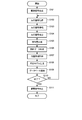
- FIG. 3 is a flowchart showing an example of the processing operation related to the learning of the analysis model in the identification device.
- This flowchart shows a part of the recognition device, specifically, the processing operation in the processor 101 of the information processing device that functions as the signal generation / measurement unit 20, the position information acquisition unit 30, the learning unit 40, and the identification unit 60. There is. After the vibration generation / acquisition unit 13 is attached to the back of the user's hand, when the input unit 107 instructs the start of learning via the input / output interface 105, the processor 101 starts the operation shown in this flowchart.
- the processor 101 generates an acoustic signal (drive signal) based on an arbitrarily set parameter by the signal generation / measurement module 1051 of the input / output interface 105 that functions as the signal generation unit 21 of the signal generation / measurement unit 20.
- the drive signal is, for example, an ultrasonic wave that sweeps from 20 kHz to 40 kHz.
- the setting of the acoustic signal does not matter, such as whether or not to sweep, whether or not to use another frequency band, and the like.
- the generated drive signal is input to the vibration generation / acquisition unit 13 of the measurement unit 10.
- the drive signal generated by the signal generation / measurement module 1051 based on the preset parameters gives vibration to the object to be registered through the vibration generation / acquisition unit 13.
- the vibration generation / acquisition unit 13 acquires the vibration that has been given to the object to be registered and has propagated inside and on the surface of the object.
- the vibration given from one piezoelectric element of the vibration generation / acquisition unit 13 is propagated to the other piezoelectric element, the object to be registered functions as a propagation path, and is given according to this propagation path.
- the frequency characteristics of vibration change.
- the vibration generation / acquisition unit 13 detects the vibration given to the object to be registered and propagated inside the object.
- the signal generation / measurement module 1051 of the input / output interface 105 that functions as the signal reception unit 22 of the signal generation / measurement unit 20 acquires the reaction signal indicated by the detected vibration (step S102).
- the signal generation / measurement module 1051 of the input / output interface 105 that functions as the signal amplification unit 23 of the signal generation / measurement unit 20 amplifies the acquired reaction signal (step S103). This is because the vibration that has passed through the object to be registered is attenuated, so it is necessary to amplify it to a level that allows processing.
- the amplified reaction signal is stored in the temporary storage unit 1032 of the data memory 103.
- the processor 101 functions as the signal extraction unit 24 of the signal generation / measurement unit 20, and extracts the reaction signal stored in the temporary storage unit 1032 at regular time intervals (step S104).
- the number of signal samples does not matter.
- the extracted reaction signal is stored in the temporary storage unit 1032 of the data memory 103.
- the processor 101 functions as the feature amount generation unit 41 of the learning unit 40 to perform the following processing operations.
- the processor 101 performs, for example, FFT (Fast Fourier Transform) on the extracted reaction signal stored in the temporary storage unit 1032 to generate a feature amount representing the acoustic frequency characteristics of the object. (Step S105).
- FFT Fast Fourier Transform
- the generated feature amount is stored in the temporary storage unit 1032 of the data memory 103.
- the processor 101 assigns a unique identifier (hereinafter, referred to as an object ID) to the generated feature amount, and generates teacher data in which the feature amount and the object ID are combined (step S106). ).
- the generated teacher data is stored in the temporary storage unit 1032 of the data memory 103.
- the processor 101 may extract the registration data created in advance from the database 50 configured in the model storage unit 1031 of the data memory 103, and generate teacher data using the registered data.
- the processor 101 functions as the model learning unit 42 of the learning unit 40 to perform the following processing operations.
- the processor 101 acquires the position information and stores the acquired position information in the temporary storage unit 1032 of the data memory 103 (step S107). Specifically, the processor 101 measures the Wi-Fi signal strength of the plurality of Wi-Fi access points 71 by the wireless communication module 1041 of the communication interface 104, and acquires the position information. Alternatively, the processor 101 measures the radio signal strength of the plurality of mobile phone base stations 72 by the wireless communication module 1042 of the communication interface 104, and acquires the position information. Alternatively, the processor 101 measures the signal strength of the beacon transmitted from at least one beacon transmitter 73 by the wireless communication module 1043 of the communication interface 104, and acquires the position information.
- the processor 101 reads the information recorded on the RFID tag 74 by the wireless communication module 1044 of the communication interface 104 to acquire the position information.
- the processor 101 acquires position information from the GPS sensor 109 via the input / output interface 105.
- the processor 101 acquires atmospheric pressure information from the atmospheric pressure sensor 110 via the input / output interface 105, and acquires altitude information.
- the position information indicates the place where each object is placed at the time of learning.
- a place kitchen, office, kitchen at home, waiting room in an office, etc. are used as information that can be uniquely identified
- location information is information that can specify a place such as latitude, longitude, and name of a place. If there is, it does not matter the form.
- the processor 101 generates and learns an analysis model in which the feature amount in the teacher data is input and the object ID in the teacher data as a label and the reference value which is the difference with respect to the input are output. (Step S108).
- the classification model and the type of the library used for the learning are not limited. For example, using a generally known machine learning library, algorithms for generating classification models such as SVM (Support Vector Machine) and neural networks obtain optimum output by performing parameter tuning etc. on the teacher data. It is also good to learn to be able to.
- Random Forest used as an algorithm for generating a classification model
- data is randomly extracted from the teacher data and a plurality of decision trees are generated.
- the number of judgment results for each label of each decision tree for the input data is output.
- the classification algorithm another classification algorithm such as DNN (Deep Neural Network) may be used.
- DNN Deep Neural Network
- the reference value may be obtained by subtracting the normalized similarity degree from "1", or may be obtained by returning the similarity degree by the reciprocal of the similarity degree or the like.
- the processor 101 registers the model itself or the parameters of the model for the analysis model and the classification model obtained by this learning process in the database 50 configured in the model storage unit 1031 of the data memory 103 (step S109). At this time, the processor 101 also registers the position information acquired and stored in the temporary storage unit 1032 in the database 50 so that the object ID to be learned can be referred to.
- the processor 101 determines whether or not the input unit 107 has instructed the end of learning via the input / output interface 105 (step S110). Here, when it is determined that the end of learning is not instructed (NO in step S110), the processor 101 repeats from the process of step S102. This makes it possible to learn about another object to be registered at that location.
- step S110 when it is determined that the end of learning is instructed (YES in step S110), the processor 101 stops the generation of the drive signal by the signal generation / measurement module 1051 of the input / output interface 105 (step S111). ). Then, the processing operation shown in this flowchart is terminated.
- the identification device selects an analysis model from the analysis models registered in the database 50 or the like using the position information. Then, the generated feature amount is input to the selected analysis model, and the object grasped from the identification target registered in the analysis model is specified.
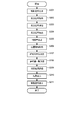
- FIG. 4 is a flowchart showing an example of a processing operation related to the identification of one gripped object in the identification.
- This flowchart shows a part of the recognition device, specifically, the processing operation in the processor 101 of the information processing device that functions as the signal generation / measurement unit 20, the position information acquisition unit 30, the learning unit 40, and the identification unit 60. There is. After the vibration generation / acquisition unit 13 is attached to the back of the user's hand, when the input unit 107 instructs the start of identification via the input / output interface 105, the processor 101 starts the operation shown in this flowchart.
- the processor 101 generates a drive signal based on an arbitrarily set parameter by the signal generation / measurement module 1051 of the input / output interface 105 that functions as the signal generation unit 21 of the signal generation / measurement unit 20 (step S201).
- the generated drive signal is input to the vibration generation / acquisition unit 13 of the measurement unit 10.
- the drive signal generated by the signal generation / measurement module 1051 gives vibration to the gripping object to be identified through the vibration generation / acquisition unit 13.
- the vibration at this time includes the frequency included in the vibration used when generating the feature amount included in the registered data regarding the learned object (hereinafter referred to as a registered object) registered in the database 50. For example, other frequencies may be mixed.
- the vibration generation / acquisition unit 13 acquires the vibration that is given to the gripping object to be identified and propagates inside and on the surface of the gripping object.
- the gripping object functions as a propagation path, and the given vibration is given according to this propagation path.
- the frequency characteristic of is changed.
- the vibration generation / acquisition unit 13 detects the vibration given to the gripping object to be identified and propagated inside the object.
- the signal generation / measurement module 1051 of the input / output interface 105 that functions as the signal reception unit 22 of the signal generation / measurement unit 20 acquires the reaction signal indicated by the detected vibration (step S202).
- the signal generation / measurement module 1051 of the input / output interface 105 that functions as the signal amplification unit 23 of the signal generation / measurement unit 20 amplifies the acquired reaction signal (step S203).
- the amplified reaction signal is stored in the temporary storage unit 1032 of the data memory 103.
- the processor 101 functions as the signal extraction unit 24 of the signal generation / measurement unit 20 to extract the reaction signal stored in the temporary storage unit 1032 at regular time intervals (step S204).
- the number of signal samples does not matter.
- the extracted reaction signal is stored in the temporary storage unit 1032 of the data memory 103.
- the processor 101 functions as a feature amount generation unit 41 of the learning unit 40, and by performing, for example, an FFT on the extracted reaction signal stored in the temporary storage unit 1032, the acoustic frequency characteristics of the object, etc. (Step S205).
- the generated feature amount is stored in the temporary storage unit 1032 of the data memory 103.
- the processor 101 functions as a model determination unit 61 of the identification unit 60 to perform the following processing operations.
- the processor 101 acquires the position information and stores the acquired position information in the temporary storage unit 1032 of the data memory 103 (step S206). Specifically, the processor 101 measures the Wi-Fi signal strength of the plurality of Wi-Fi access points 71 by the wireless communication module 1041 of the communication interface 104, and acquires the position information. Alternatively, the processor 101 measures the radio signal strength of the plurality of mobile phone base stations 72 by the wireless communication module 1042 of the communication interface 104, and acquires the position information. Alternatively, the processor 101 measures the signal strength of the beacon transmitted from at least one beacon transmitter 73 by the wireless communication module 1043 of the communication interface 104, and acquires the position information.
- the processor 101 reads the information recorded on the RFID tag 74 by the wireless communication module 1044 of the communication interface 104 to acquire the position information.
- the processor 101 acquires position information from the GPS sensor 109 via the input / output interface 105.
- the processor 101 acquires atmospheric pressure information from the atmospheric pressure sensor 110 via the input / output interface 105, and acquires altitude information.
- the processor 101 is selected from a large number of analysis models registered in the database 50 configured in the model storage unit 1031 of the data memory 103 based on the position information acquired and stored in the temporary storage unit 1032.
- the analytical model associated with the most similar location information is determined (step S207). For example, the processor 101 refers to the latitude / longitude which is the acquired position information, and selects an analysis model associated with the position information having the nearest latitude / longitude. If there are multiple analysis models associated with the location information, select those multiple analysis models.
- the selected analysis model is stored in the temporary storage unit 1032 of the data memory 103.
- the type and selection method of the location information to be used may be in any form.
- the method of determining the analysis model it is conceivable to use a combination of latitude / longitude and location type.
- the latitude / longitude learning stage the latitude / longitude is divided into sections of a certain size (so-called mesh), and an analysis model is created for each section.
- the latitude and longitude representing the section are associated with the analysis model.
- the identification stage at least one analysis model closest to the latitude and longitude specified as position information is used.
- an analysis model is created for each location to be classified.
- the information for specifying the location to be classified there is a Wi-Fi access point 71 which is the connection destination network device information of the information device possessed by the user, but if it is a method that can specify the location such as a GPS sensor 109, The form does not matter.
- the location is identified from the acquired location information, and the corresponding analysis model is selected and used.
- the processor 101 functions as the identification determination unit 62 of the identification unit 60, and acquires one or more analysis models stored in the temporary storage unit 1032 of the data memory 103 in the above step S205 and temporarily stores the unit 1032.
- the feature amount stored in is input as test data, and a list of reference values of each analysis model is acquired (step S208).
- the list of acquired reference values is stored in the temporary storage unit 1032 of the data memory 103.
- the processor 101 functions as the determination result evaluation unit 63 of the identification unit 60, and identifies the smallest reference value from the reference value list stored in the temporary storage unit 1032.
- the processor 101 determines in the database 50 that the registered object associated with the same feature amount as the specified reference value is a similar object.
- the processor 101 stores the object ID of the determined registered object in the output information storage unit 1033 of the data memory 103 as the identification result of the gripping object to be identified (step S209).
- a threshold value for determination may be set for the degree of similarity, and similar objects may be determined only when the specified reference value is smaller than this threshold value.
- the processor 101 displays and outputs the object ID, which is the identification result stored in the output information storage unit 1033, to the display unit 108 via the input / output interface 105 (step S210).
- the processor 101 stops the generation of the drive signal by the signal generation / measurement module 1051 of the input / output interface 105 (step S211). Then, the processing operation shown in this flowchart is terminated.
- the identification device acquires the position information of the vibration generation / acquisition unit 13 including the sensor for measuring the gripping state of the gripping object to be identified and the sensor wearer wearing the sensor.
- a position information acquisition unit 30 is provided, and an identification unit 60 that identifies a gripping object held by the sensor wearer based on the gripping state measured by the sensor and the position information acquired by the position information acquisition unit 30. Therefore, by combining the position information in addition to the data obtained from the sensor indicating the gripping state of the gripping object, it is possible to distinguish objects having similar shapes as different objects. That is, depending on the place where identification is performed (for example, a kitchen, a desk at home, an office, etc.), the objects may have different shapes even if they have similar shapes.
- the objects existing around the place can be identified to some extent. Therefore, at the time of identification, by narrowing down the candidates to be identified by using the position information, it is possible to exclude them from the identification target because the positions are different even if they have similar shapes, and the probability of erroneous identification of the gripped object is reduced. Can be done.
- the identification device is a database 50 in which, for each of a plurality of objects to be registered, a feature amount indicating a gripping state measured by a sensor is registered in association with the position information acquired by the position information acquisition unit 30. Further, the identification unit 60 narrows down one or more candidate objects from a plurality of objects to be registered registered in the database 50 based on the position information acquired by the position information acquisition unit 30, and narrows down one or more. Among the candidate objects, one candidate object having a feature amount corresponding to the feature amount indicating the gripping state of the gripping object measured by the sensor is identified as the object to be identified.
- the processing time can be shortened.
- the identification device further includes a learning unit 40 that registers the feature amount of each of the plurality of objects to be registered in the database 50 in association with the position information acquired by the position information acquisition unit 30. .. Therefore, it is possible to associate all of the objects to be registered with the position information, and it is also possible to add a new object to be registered to the database 50.
- the feature amount indicating the gripping state measured by the sensor includes the feature amount indicating the frequency characteristic based on the vibration propagating inside the object, and the sensor gives the object the first feature amount.
- the vibration of the above is generated by the piezoelectric element, and the reaction signal which is the detection signal corresponding to the second vibration propagating inside the object among the first vibration given to the object is acquired, and the identification unit 60 acquires.
- a feature amount indicating the frequency characteristic of the second vibration is generated based on the generated reaction signal, and a feature amount corresponding to the generated feature amount is generated from a plurality of objects to be registered registered in the database 50.
- One candidate object having is identified as an object to be identified. Therefore, any object to which vibration propagates can be applied as an object to be identified.
- the database 50 inputs the generated feature amount for the grasped object to be identified, and the feature amount of at least one identified object to be registered and the feature amount of the gripped object.
- a model that outputs a value based on the difference between the object and the grip object in association with an identifier uniquely assigned to the gripping object is stored in association with the position information acquired by the position information acquisition unit 30, and the model is registered in a plurality of registrations. For each of the target objects, learning is performed based on the feature quantity indicating the frequency characteristic of the second vibration based on the detection signal acquired by the sensor, and the identification unit 60 uses the narrowed-down model of one or more candidate objects as a model.
- the gripping object Enter the feature amount generated for the gripping object to be identified, and output it in association with the value that is most relevant to the feature amount of the gripping object among the values output from the model of one or more candidate objects.
- the gripping object is identified. Therefore, it is possible to appropriately identify the gripping object to be identified by using the identified object.
- the position information acquisition unit 30 detects the strength of the radio signal from the transmission device that transmits the radio signal, and estimates the position with respect to the transmission device based on the detected strength. Is available.
- the location information acquisition unit 30 may receive a wireless communication module 1041 that communicates with the Wi-Fi access point 71, a wireless communication module 1042 that communicates with the mobile phone base station 72, or a wireless communication module that receives a beacon from the beacon transmitter 73. Includes 1043.
- the position information acquisition unit 30 can include a position detection sensor that detects the position information.
- the position detection sensor includes, for example, a GPS sensor 109 or a barometric pressure sensor 110.
- the position information acquisition unit 30 can include a communication device that receives the position information transmitted from the position information transmission device.
- the communication device includes a wireless communication module 1043 that receives the position information contained in the beacon from the beacon transmitter 73 or a wireless communication module 1044 that reads the position information recorded on the RFID tag 74.
- the identification device is described as a device that analyzes an acoustic spectrum obtained by analyzing vibration propagating inside an object and identifies the object to be grasped based on the difference in the acoustic spectrum. ..
- the identification device may be a device for identifying the gripped object by another method such as using a glove type sensor as in Non-Patent Document 1.
- the information processing device that constitutes a part of the identification device does not require all of the wireless communication modules 1041 to 1044, and may have at least one. Further, when the position information acquisition unit 30 is configured by using the GPS sensor 109 or the barometric pressure sensor 110, it is not necessary to have any of the wireless communication modules 1041 to 1044.
- the information processing device may have at least one of the wireless communication modules 1041 to 1044, the GPS sensor 109, and the pressure sensor 110 for constituting the position information acquisition unit 30.
- the location information acquisition unit 30 may acquire location information from an information processing device equipped with a GPS sensor, such as a smartphone carried by the user, by wireless communication such as Wi-Fi or Bluetooth.
- the position information acquisition unit 30 is composed of the wireless communication modules 1041 and 1043 of the communication interface 104.
- the processing operations shown in FIGS. 3 and 4 are not limited to the order of the illustrated steps, and can be performed in an order different from the illustrated order and / or in parallel with another step. Is.
- the processing of generating teacher data in step S106 and the processing of acquiring position information in step S107 may be performed in the reverse order, or may be performed in parallel.
- the position information acquisition process in step S107 is taken out of the loop of steps S102 to S110 and once before the start of the loop. It may be possible to acquire only the position information.
- the position information acquisition processing in step S206 may be performed at any stage as long as it is before the analysis model determination is performed in step S207.
- the processing function unit of the signal generation / measurement unit 20, the position information acquisition unit 30, the learning unit 40, the database 50, and the identification unit 60 is described as being configured by one information processing device. It may be configured by a plurality of information processing devices by arbitrary division.
- the database 50 may be configured as an information processing device or a server device different from the information processing device constituting the identification device, which can communicate via the network by the communication interface 104.
- the learning of the registered object in the database 50 is carried out by using an information processing device different from the identification device, and the identification device identifies by using the registered data related to the registered object in the database 50.
- the target gripping object may be identified.
- the method described in the above embodiment is, for example, a magnetic disk (floppy (registered trademark) disk, hard disk, etc.) or an optical disk (CD-ROM, DVD) as a program (software means) that can be executed by a computer (computer). , MO, etc.), stored in a recording medium such as a semiconductor memory (ROM, RAM, flash memory, etc.), or transmitted and distributed by a communication medium.
- the program stored on the medium side also includes a setting program for configuring the software means (including not only the execution program but also the table and the data structure) to be executed by the computer in the computer.
- a computer that realizes this device reads a program recorded on a recording medium, constructs software means by a setting program in some cases, and executes the above-mentioned processing by controlling the operation by the software means.
- the recording medium referred to in the present specification is not limited to distribution, and includes storage media such as magnetic disks and semiconductor memories provided in devices connected inside a computer or via a network.
- the present invention is not limited to the above embodiment, and can be variously modified at the implementation stage without departing from the gist thereof.
- each embodiment may be carried out in combination as appropriate as possible, in which case the combined effect can be obtained.
- the above-described embodiment includes inventions at various stages, and various inventions can be extracted by an appropriate combination in a plurality of disclosed constituent requirements.
Landscapes
- Engineering & Computer Science (AREA)
- Physics & Mathematics (AREA)
- General Physics & Mathematics (AREA)
- Theoretical Computer Science (AREA)
- Biochemistry (AREA)
- Analytical Chemistry (AREA)
- General Health & Medical Sciences (AREA)
- Chemical & Material Sciences (AREA)
- Immunology (AREA)
- Pathology (AREA)
- Life Sciences & Earth Sciences (AREA)
- Health & Medical Sciences (AREA)
- General Engineering & Computer Science (AREA)
- Databases & Information Systems (AREA)
- Signal Processing (AREA)
- Evolutionary Computation (AREA)
- Human Computer Interaction (AREA)
- Artificial Intelligence (AREA)
- Acoustics & Sound (AREA)
- Data Mining & Analysis (AREA)
- Mechanical Engineering (AREA)
- Information Retrieval, Db Structures And Fs Structures Therefor (AREA)
- Measurement Of The Respiration, Hearing Ability, Form, And Blood Characteristics Of Living Organisms (AREA)
- User Interface Of Digital Computer (AREA)
Abstract
一実施形態に係る識別装置は、識別対象である把持オブジェクトの把持状態を計測するセンサと、センサを装着しているセンサ装着者の位置情報を取得する位置情報取得部と、センサが計測した把持状態と位置情報取得部が取得した位置情報とに基づいて、センサ装着者が把持している把持オブジェクトを識別する識別部と、を備える。
Description
この発明の実施形態は、識別装置、識別方法及び識別プログラムに関する。
非特許文献1は、ユーザが装着したグローブ型センサを用いて、立体物であるオブジェクトの握り方によって異なる、オブジェクトと手の接触面の違いに応じて、ユーザが把持しているオブジェクトを検出する手法を開示している。
Subramanian Sundaram, Petr Kellnhofer, Yunzhu Li, Jun-Yan Zhu, Antonio Torralba, Wojciech Matusik. Learning the signatures of the human grasp using a scalable tactile glove. Nature volume 569, pages 698-702(2019).
しかしながら、非特許文献1に開示の手法は、類似形状を有するオブジェクトを把持した場合、類似した計測データとなるため、これらのオブジェクトの区別が困難である。
この発明は、把持した類似形状を有するオブジェクトを区別可能とする技術を提供しようとするものである。
上記課題を解決するために、この発明の一態様に係る識別装置は、識別対象である把持オブジェクトの把持状態を計測するセンサと、前記センサを装着しているセンサ装着者の位置情報を取得する位置情報取得部と、前記センサが計測した前記把持状態と前記位置情報取得部が取得した前記位置情報とに基づいて、前記センサ装着者が把持している前記把持オブジェクトを識別する識別部と、を備える。
この発明の一態様によれば、位置情報という追加の情報を用いることで、把持した類似形状を有するオブジェクトを区別可能とする技術を提供することができる。
以下、図面を参照して、この発明に係わる一実施形態を説明する。
なお、この実施形態は、オブジェクト内部を伝搬する振動を解析して得られる音響スペクトルを解析し、この音響スペクトルの違いに基づいて識別対象である把持しているオブジェクトを識別する識別装置を例にして説明する。この識別装置は、形状、素材、境界条件等によって変化する共振特性を音響スペクトルにより解析し、このスペクトルの違いに基づいて識別対象の把持オブジェクトを識別する。
また、この識別装置は、任意に選択可能な、識別対象とするすべてのオブジェクトのデータを用いて、分類モデルを生成する。このため、識別装置は、この違いに応じて、識別対象のオブジェクトが、ある1つの対象Aであるか否かだけでなく、どのオブジェクトであるのかを区別することが可能である。すなち、識別装置は、識別対象のオブジェクトが、例えば、対象A、対象B、対象Cの何れであるのかを区別することができる。
図1は、この発明の一実施形態に係る識別装置の構成の一例を示すブロック図である。識別装置は、計測部10、信号生成・測定部20、位置情報取得部30、学習部40、データベース50、及び識別部60を有している。
ここで、計測部10は、識別対象である把持オブジェクトの把持状態を計測するセンサ及びそのセンサを生体に装着するための部位である。この計測部10は、生体接着部11、筐体補強部12、及び振動発生・取得部13の3つの機能ブロックを含む。
生体接着部11は、センサである振動発生・取得部13を生体に貼り付ける。この生体接着部11としては、粘着性を有し、生体の皮膚に固定できるものであれば、実現方法は問わない。例えば、生体用粘着テープなどがある。
筐体補強部12は、振動発生・取得部13を継続して利用するために、振動発生・取得部13の強度を補強する。
振動発生・取得部13は、識別対象である把持オブジェクトの把持状態を計測するセンサ、例えば手指の状態を計測可能なセンサである。センサの出力は、把持するオブジェクトに応じた手や指の把持姿勢に伴って変化する。この振動発生・取得部13は、例えば、オーディオインタフェースと、任意の振動を発生・取得可能な、互いに接触しない2つの圧電素子とを含む。圧電素子は、例えばピエゾ素子により実現できる。一方の圧電素子は、信号生成・測定部20において生成された信号(以下、駆動信号と称する)と同一の周波数特徴を有する振動を発生する。また、もう一方の圧電素子は、振動を受信する。受信した振動信号(以下、反応信号と称する)は、信号生成・測定部20に送信される。学習対象つまり登録対象のオブジェクトまたは識別対象のオブジェクトと接触しつつ、且つ、振動を伝搬できる機構であれば、その形態及び素材は問わない。
また、信号生成・測定部20は、任意の周波数特性を持つ駆動信号を生成し、それを計測部10の振動発生・取得部13の圧電素子に入力し、振動発生・取得部13からの反応信号を取得する。信号生成・測定部20は、マイクロコンピュータやパーソナルコンピュータ(以下、PCと略記する。)等の情報処理装置により構成することができる。反応信号の要件として、音響信号のような周波数特性を有する振動であれば、その振動の形態及び種類は問わない。この信号生成・測定部20は、信号生成部21、信号受信部22、信号増幅部23、及び信号抽出部24の4つの機能ブロックを含む。
信号生成部21は、計測部10の振動発生・取得部13に入力する駆動信号を生成する。
信号受信部22は、計測部10の振動発生・取得部13からの反応信号を取得する。
信号増幅部23は、信号受信部22において取得した反応信号を増幅する。
信号抽出部24は、信号増幅部23において増幅された反応信号を一定時間区間ごとに抽出し、学習部40に出力する。
なお、振動発生・取得部13は、ここでは圧電素子を用いるものとしたが、電気信号から振動を発生させるもの、振動を電気信号とするものであれば、形態を問わない。このときの計測部10と信号生成・測定部20とを接続する形態は、振動発生・取得部13へのデータの送受信ができる機能を有していれば、その形態は問わない。加えて、計測部10を制御する形態についても、電気信号を生成及び受信することができる形態であれば、独立型のマイクロコンピュータやPC等、形態を問わない。
また、位置情報取得部30は、センサである計測部10の振動発生・取得部13を接着した生体、つまりセンサの装着者の位置を取得または特定するものである。この位置情報取得部30は、センサの装着者の位置を取得または特定できるものであれば、その形態及び実現方法は問わない。例えば、位置情報取得部30は、GPS(測位衛星システム)、使用しているWi-Fiアクセスポイントや携帯電話無線基地局の信号強度、Bluetooth(登録商標)ビーコンなどを利用して、センサ装着者の位置を取得することができる。位置情報取得部30は、取得した位置を示す位置情報を、学習部40及び識別部60に出力する。
また、学習部40は、信号生成・測定部20の信号抽出部24からの反応信号より機械学習のための特徴量を生成し、その生成した特徴量から解析モデルを構成し、構成した解析モデルをデータベース50に登録する。学習部40は、PC等の情報処理装置によって構成することができる。この学習部40は、特徴量生成部41及びモデル学習部42の2つの機能ブロックを含む。
特徴量生成部41は、信号抽出部24において得られた反応信号の波形に基づき、把持しているオブジェクトの特徴量を生成する。
モデル学習部42は、特徴量生成部41より得られた特徴量と把持しているオブジェクトとを組とした解析モデルを生成・学習して、データベース50に登録する。このデータベース50への登録の際、モデル学習部42は、位置情報取得部30からの位置情報を、解析モデルと関連付けて登録する。こうして、モデル学習部42は、解析モデルを位置情報と関連付けて学習する。
識別部60は、位置情報取得部30からの位置情報に基づいてデータベース50より使用する解析モデルを選択し、選択した解析モデルに基づき、学習部40の特徴量生成部41より得られた特徴量から、把持オブジェクトを識別する。識別部60は、PC等の情報処理装置によって構成することができる。この識別部60は、モデル決定部61、識別判定部62、及び判定結果評価部63の3つの機能ブロックを含む。
モデル決定部61は、位置情報取得部30からの位置情報より、用いる解析モデルを決定する。
識別判定部62は、モデル決定部61において決定した使用する解析モデルに、入力として、学習部40の特徴量生成部41において生成した特徴量を入力し、出力として、把持オブジェクトを判定するための数値を求める。
判定結果評価部63は、識別判定部62において求めた数値を基に、把持オブジェクトを識別する。
図2は、図1の識別装置の一部、具体的には信号生成・測定部20、位置情報取得部30、学習部40、及び識別部60を構成する情報処理装置のハードウェア構成の一例を示す図である。情報処理装置は、図2に示すように、例えばPCなどのコンピュータにより構成され、CPU(Central Processing Unit)等のハードウェアプロセッサ101を有する。そして、情報処理装置では、このプロセッサ101に対し、プログラムメモリ102と、データメモリ103と、通信インタフェース104と、入出力インタフェース105とが、バス106を介して接続される。
通信インタフェース104は、例えば一つ以上の有線または無線の通信モジュールを含むことができる。図2に示す例では、四つの無線通信モジュール1041~1044を示している。
無線通信モジュール1041は、例えば、Wi-Fiアクセスポイント(図2では、アクセスポイントをAPと略記している。)71と無線接続し、Wi-Fiアクセスポイント71を介してネットワーク上の他の情報処理装置やサーバ装置との間で通信を行い、各種情報を送受信することができる。ネットワークは、インターネットを含むIP網と、このIP網にアクセスするためのアクセス網とから構成される。アクセス網としては、例えば公衆有線網や携帯電話網、有線LAN(Local Area Network)、無線LAN、CATV(Cable Television)等が用いられる。また、無線通信モジュール1041は、Wi-Fiの信号強度を測定する機能を有し、その測定した信号強度をプロセッサ101に出力する。プロセッサ101は、無線信号を送信する送信装置である各Wi-Fiアクセスポイント71の設置位置に関する先見情報と、複数のWi-Fiの受信信号強度とに基づいて、各Wi-Fiアクセスポイント71に対する当該情報処理装置の位置を推定することができる。当該情報処理装置は、オブジェクトを把持するユーザの近傍に配置されるので、ユーザの位置、延いてはオブジェクトの位置を推定することができる。すなわち、プロセッサ101及び無線通信モジュール1041は、位置情報取得部30として機能することができる。
無線通信モジュール1042は、携帯電話基地局72と無線接続し、携帯電話基地局72を介してネットワーク上の他の情報処理装置やサーバ装置との間で通信を行い、各種情報を送受信することができる。また、無線通信モジュール1042は、携帯電話基地局72との間の無線の受信信号強度を測定する機能を有し、その測定した信号強度をプロセッサ101に出力する。プロセッサ101は、無線信号を送信する送信装置である各携帯電話基地局72の設置位置に関する先見情報と、複数の携帯電話基地局72の受信信号強度とに基づいて、当該情報処理装置の位置を推定することができる。すなわち、プロセッサ101及び無線通信モジュール1042も、位置情報取得部30として機能することができる。
無線通信モジュール1043は、Bluetooth等の近距離無線技術を利用した通信モジュールであり、ビーコン発信機73から送信されるビーコンの信号強度を測定して、その測定した信号強度をプロセッサ101に出力する。プロセッサ101は、各ビーコン発信機73の設置位置に関する先見情報と少なくとも一つのビーコンの信号強度とに基づいて当該情報処理装置の位置範囲を特定することができる。あるいは、プロセッサ101は、先見情報と複数のビーコンの信号強度を用いて、当該情報処理装置の位置を推定したりすることができる。また、ビーコン発信機73が送信するビーコンに、当該ビーコン発信機73の位置情報を含めることもでき、この位置情報を利用すれば、ビーコン発信機73の設置位置に関する先見情報は無くても、当該情報処理装置の位置を推定することができる。すなわち、ビーコン発信機73は、無線信号を送信する送信装置であるだけでなく、位置情報を送信する位置情報送信装置でもあり、無線通信モジュール1043は、位置情報を受信する通信装置である。よって、プロセッサ101及び無線通信モジュール1043は、位置情報取得部30として機能することができる。
無線通信モジュール1044は、RFID(Radio Frequency Identifier)タグ74を読み取る通信モジュールであり、RFIDタグ74に記録された情報を読み取って、その読み取った情報をプロセッサ101に出力する。RFIDタグ74は、位置情報を記録することができる。すなわち、RFIDタグ74は、位置情報を送信する位置情報送信装置となり、無線通信モジュール1044は、位置情報を受信する通信装置である。したがって、プロセッサ101は、この読み取った位置情報に基づいて、当該情報処理装置の位置を取得することができる。すなわち、プロセッサ101及び無線通信モジュール1044は、位置情報取得部30として機能することができる。
また、入出力インタフェース105には、上記計測部10が接続されている。入出力インタフェース105は、例えば、上記信号生成・測定部20の信号生成部21、信号受信部22、及び信号増幅部23として機能する信号生成・測定モジュール1051を含む。
さらに、入出力インタフェース105には、入力部107、表示部108、GPSセンサ109、及び気圧センサ110が接続されている。
入力部107及び表示部108は、例えば液晶または有機EL(Electro Luminescence)を使用した表示デバイスの表示画面上に、静電方式または圧力方式を採用した入力検知シートを配置した、いわゆるタブレット型の入力・表示デバイスを用いたものが用いられることができる。なお、入力部107及び表示部108は独立するデバイスにより構成されてもよい。入出力インタフェース105は、上記入力部107において入力された操作情報をプロセッサ101に入力すると共に、プロセッサ101で生成された表示情報を表示部108に表示させる。
なお、入力部107及び表示部108は、入出力インタフェース105に接続されていなくてもよい。入力部107及び表示部108は、通信インタフェース104と直接またはネットワークを介して接続するための通信ユニットを備えることで、プロセッサ101との間で情報の授受を行い得る。
GPSセンサ109は、GPS信号を受信して、位置を検出する測位ユニットである。入出力インタフェース105は、GPSセンサ109における測位結果を示す位置情報をプロセッサ101に入力する。したがって、位置情報取得部30は、位置情報を検出する位置検出センサであるGPSセンサ109を含むことができる。
気圧センサ110は、気圧を測定する。入出力インタフェース105は、気圧センサ110において測定された気圧を示す気圧情報をプロセッサ101に入力する。プロセッサ101は、この気圧情報に基づいて、当該情報処理装置の高度を取得することができる。プロセッサ101は、この取得した高度に基づいて、他の位置情報取得部30の構成部分によって取得した位置情報を補正することができる。すなわち、プロセッサ101、入出力インタフェース105、及び気圧センサ110は、位置情報取得部30として機能することができる。したがって、位置情報取得部30は、位置情報を検出する位置検出センサの一部である気圧センサ110を含むことができる。
また、入出力インタフェース105は、フラッシュメモリなどの半導体メモリといった記録媒体のリード/ライト機能を有しても良いし、あるいは、そのような記録媒体のリード/ライト機能を持ったリーダライタとの接続機能を有しても良い。これにより、識別装置に対して着脱自在な記録媒体を、解析モデルを保持するデータベースとすることができる。入出力インタフェース105は、さらに、他の機器との接続機能を有して良い。
また、プログラムメモリ102は、非一時的な有形のコンピュータ可読記憶媒体として、例えば、HDD(Hard Disk Drive)またはSSD(Solid State Drive)等の随時書込み及び読出しが可能な不揮発性メモリと、ROM(Read Only Memory)等の不揮発性メモリとが組合せて使用されたものである。このプログラムメモリ102には、プロセッサ101が一実施形態に係る各種制御処理を実行するために必要なプログラムが格納されている。すなわち、上記の信号生成・測定部20、位置情報取得部30、学習部40、及び識別部60の各部における処理機能部は、何れも、プログラムメモリ102に格納されたプログラムを上記プロセッサ101により読み出させて実行させることにより実現され得る。なお、これらの処理機能部の一部または全部は、特定用途向け集積回路(ASIC:Application Specific Integrated Circuit)またはFPGA(field-programmable gate array)などの集積回路を含む、他の多様な形式によって実現されても良い。
また、データメモリ103は、有形のコンピュータ可読記憶媒体として、例えば、上記の不揮発性メモリと、RAM(Random Access Memory)等の揮発性メモリとが組合せて使用されたものである。このデータメモリ103は、各種処理が行われる過程で取得及び作成された各種データが記憶されるために用いられる。すなわち、データメモリ103には、各種処理が行われる過程で、適宜、各種データを記憶するための領域が確保される。そのような領域として、データメモリ103には、例えば、モデル記憶部1031、一時記憶部1032、及び出力情報記憶部1033を設けることができる。
モデル記憶部1031は、学習部40が学習した解析モデルを記憶する。すなわち、データベース50が、このモデル記憶部1031に構成されることができる。
一時記憶部1032は、プロセッサ101が、上記信号生成・測定部20、位置情報取得部30、学習部40、及び識別部60としての動作を実施した際に取得または生成する、反応信号、特徴量、教師データ、位置情報、解析モデル、参考値、等のデータを記憶する。
出力情報記憶部1033は、プロセッサ101が上記識別部60としての動作を実施した際に得られる出力情報を記憶する。
次に、識別装置の動作を説明する。
本実施形態では、識別装置は、把持オブジェクトの識別に先立って、先ず、手指の状態を計測可能なセンサを用いて把持オブジェクトと関連付けた解析モデルを生成し、その生成した解析モデルに位置情報を関連付けて、登録データとしてデータベース50に保存する。
本実施形態では、識別装置は、把持オブジェクトの識別に先立って、先ず、手指の状態を計測可能なセンサを用いて把持オブジェクトと関連付けた解析モデルを生成し、その生成した解析モデルに位置情報を関連付けて、登録データとしてデータベース50に保存する。
先ず、計測部10の振動発生・取得部13を、生体接着部11を用いて対象者となるユーザの手の甲に貼り付ける。振動発生・取得部13が発生する振動は、音響信号のような周波数特性を有する振動であれば、その形態及び種類は問わない。本実施形態においては、音響信号を例として挙げて説明する。
図3は、識別装置における解析モデルの学習に係わる処理動作の一例を示すフローチャートである。このフローチャートは、認識装置の一部、具体的には信号生成・測定部20、位置情報取得部30、学習部40、及び識別部60として機能する情報処理装置のプロセッサ101における処理動作を示している。振動発生・取得部13をユーザの手の甲に貼り付けた後、入出力インタフェース105を介して入力部107から学習の開始が指示されると、プロセッサ101は、このフローチャートに示す動作を開始する。
先ず、プロセッサ101は、信号生成・測定部20の信号生成部21として機能する入出力インタフェース105の信号生成・測定モジュール1051により、任意に設定したパラメータに基づく音響信号(駆動信号)を生成する(ステップS101)。駆動信号は、例えば、20kHzから40kHzまで掃引する超音波とする。但し、掃引するか否か、他の周波数帯域の利用の有無等、音響信号の設定は問わない。生成された駆動信号は、計測部10の振動発生・取得部13に入力される。
ユーザは、登録対象のオブジェクトを把持する。これにより、予め設定したパラメータに基づいて信号生成・測定モジュール1051で生成した駆動信号により、振動発生・取得部13を通じて登録対象のオブジェクトに振動が与えられる。振動発生・取得部13は、登録対象オブジェクトに与えられ、オブジェクト内部及び表面を伝搬してきた振動を取得する。ここで、振動発生・取得部13の一方の圧電素子から与えられる振動が他方の圧電素子まで伝搬される際に、登録対象オブジェクトが伝搬路として機能し、この伝搬路に応じて、与えられた振動の周波数特性が変化する。
振動発生・取得部13は、登録対象のオブジェクトに与えられて当該オブジェクトの内部を伝搬してきた振動を検出する。信号生成・測定部20の信号受信部22として機能する入出力インタフェース105の信号生成・測定モジュール1051は、この検出された振動で示される反応信号を取得する(ステップS102)。
信号生成・測定部20の信号増幅部23として機能する入出力インタフェース105の信号生成・測定モジュール1051は、取得した反応信号を増幅する(ステップS103)。これは、登録対象オブジェクトを通過した振動は減衰することから、処理が可能となるレベルまで増幅を行う必要があるためである。増幅された反応信号は、データメモリ103の一時記憶部1032に記憶されていく。
プロセッサ101は、次に、信号生成・測定部20の信号抽出部24として機能して、一時記憶部1032に記憶した反応信号を、一定時間区間ごとに抽出する(ステップS104)。信号のサンプル数は問わない。抽出された反応信号は、データメモリ103の一時記憶部1032に記憶される。
次に、プロセッサ101は、学習部40の特徴量生成部41として機能して、以下の処理動作を行う。
先ず、プロセッサ101は、一時記憶部1032に記憶した抽出された反応信号に対して、例えばFFT(Fast Fourier Transform:高速フーリエ変換)を行うことで、オブジェクトの音響周波数特性等を表す特徴量を生成する(ステップS105)。生成した特徴量は、データメモリ103の一時記憶部1032に記憶される。
次に、プロセッサ101は、その生成した特徴量に対して一意な識別子(以下、オブジェクトIDと称する。)を付与し、これら特徴量とオブジェクトIDとを組とする教師データを生成する(ステップS106)。生成した教師データは、データメモリ103の一時記憶部1032に記憶される。さらに、プロセッサ101は、データメモリ103のモデル記憶部1031に構成したデータベース50から予め作成した登録データを抽出し、それを用いて教師データを生成しても良い。
次に、プロセッサ101は、学習部40のモデル学習部42として機能して、以下の処理動作を行う。
先ず、プロセッサ101は、位置情報を取得し、その取得した位置情報をデータメモリ103の一時記憶部1032に記憶する(ステップS107)。具体的には、プロセッサ101は、通信インタフェース104の無線通信モジュール1041により、複数のWi-Fiアクセスポイント71についてのWi-Fiの信号強度を測定して、位置情報を取得する。あるいは、プロセッサ101は、通信インタフェース104の無線通信モジュール1042により、複数の携帯電話基地局72についての無線の信号強度を測定して、位置情報を取得する。あるいは、プロセッサ101は、通信インタフェース104の無線通信モジュール1043により、少なくとも一つのビーコン発信機73から送信されるビーコンの信号強度を測定して、位置情報を取得する。あるいは、プロセッサ101は、通信インタフェース104の無線通信モジュール1044により、RFIDタグ74に記録された情報を読み取って、位置情報を取得する。あるいは、プロセッサ101は、入出力インタフェース105を介して、GPSセンサ109より位置情報を取得する。また、プロセッサ101は、入出力インタフェース105を介して、気圧センサ110から気圧情報を取得して、高度情報を取得する。
なお、位置情報は、学習時に各オブジェクトが置かれている場所を示す。場所の例としては、キッチン、オフィス、自宅のキッチン、オフィスの給仕室、等を、それらが一意に特定できる情報とし、位置情報は、緯度や経度、場所の名称等、場所を特定できる情報であれば、形態を問わない。
次に、プロセッサ101は、上記教師データにおける特徴量を入力とし、ラベルとしての上記教師データにおけるオブジェクトIDと、上記入力に対する差である参考値と、を出力とする、解析モデルを生成及び学習する(ステップS108)。教師データに対してパラメータチューニング等を実施することにより最適な出力を得られるよう学習することが可能であれば、分類モデル及びその学習に用いるライブラリの種別は問わない。例えば、一般的に公知な機械学習ライブラリを用い、SVM(Support Vector Machine)やニューラルネットワークなどの分類モデル生成用のアルゴリズムが、教師データに対してパラメータチューニング等を実施することにより最適な出力を得られるよう学習することとしても良い。
この学習において、例えば、SVMをモデル生成用のアルゴリズムとする場合には、入力に対して解析モデルが持つ各ラベルに対する類似度等を示すスコアが出力される。例えば、類似度が正規化されて「0」から「1」の間で表現される場合には、「1-(類似度)」として出力されることができる。
あるいは、学習において、例えば、Random Forestを分類モデル生成用のアルゴリズムとする場合には、教師データからランダムにデータを抽出し、複数の決定木を生成する。入力データに対する各決定木の各ラベルへの判定結果数が出力される。この判定結果数が高いほど、良いものであるため、「(判定回数)―(判定結果数)」を参考値として出力する。
また、分類アルゴリズムは、他のDNN(Deep Neural Network)等の分類アルゴリズムを用いても構わない。その場合、参考値は、「1」から正規化した類似度を減算したものでも良いし、類似度の逆数などによって類似度を返還して得ても良い。
そして、プロセッサ101は、この学習処理によって得られた解析モデル及び分類モデルについて、モデルそのもの、またはモデルのパラメータを、データメモリ103のモデル記憶部1031に構成したデータベース50に登録する(ステップS109)。このとき、プロセッサ101は、学習させるオブジェクトIDに対して、上記取得して一時記憶部1032に記憶してある位置情報もデータベース50に登録して参照可能な状態とする。
こうして、一つの登録対象のオブジェクトについての学習が終了したならば、プロセッサ101は、入出力インタフェース105を介して入力部107から学習の終了が指示されたか否か判断する(ステップS110)。ここで、学習の終了が指示されていないと判断した場合(ステップS110のNO)には、プロセッサ101は、上記ステップS102の処理から繰り返す。これにより、その場所での別の登録対象オブジェクトについての学習を行うことができる。
これに対して、学習の終了が指示されたと判断した場合(ステップS110のYES)には、プロセッサ101は、入出力インタフェース105の信号生成・測定モジュール1051による駆動信号の生成を停止する(ステップS111)。そして、このフローチャートに示す処理動作を終了する。
その後、別の場所に移動して、その場所において登録対象オブジェクトについて、同様にして学習を行うことができる。こうして、対応付けた位置情報を基に、場所ごとに解析モデルを生成及び学習する。また、この学習処理によって得られた分類モデルについても、モデルそのもの、またはモデルのパラメータを、データベース50に登録する。
次に、識別対象であるオブジェクトを把持して識別する際の識別装置の動作を説明する。識別装置は、データベース50等に登録された解析モデルから位置情報を用いて解析モデルを選定する。そして、生成した特徴量を選定した解析モデルに入力し、解析モデルに登録された識別対象から把持したオブジェクトを指定する。これらの具体的な処理を、以下に説明する。
図4は、識別における一つの把持オブジェクトの識別に係わる処理動作の一例を示すフローチャートである。このフローチャートは、認識装置の一部、具体的には信号生成・測定部20、位置情報取得部30、学習部40、及び識別部60として機能する情報処理装置のプロセッサ101における処理動作を示している。振動発生・取得部13をユーザの手の甲に貼り付けた後、入出力インタフェース105を介して入力部107から識別の開始が指示されると、プロセッサ101は、このフローチャートに示す動作を開始する。
先ず、プロセッサ101は、信号生成・測定部20の信号生成部21として機能する入出力インタフェース105の信号生成・測定モジュール1051により、任意に設定したパラメータに基づく駆動信号を生成する(ステップS201)。生成された駆動信号は、計測部10の振動発生・取得部13に入力される。
ユーザは、識別対象のオブジェクトを把持する。これにより、信号生成・測定モジュール1051で生成した駆動信号により、振動発生・取得部13を通じて識別対象の把持オブジェクトに振動が与えられる。このときの振動は、データベース50に登録されている学習済みのオブジェクト(以下、登録オブジェクトと称する。)に関する登録データに含まれる特徴量を生成する際に用いた振動に含まれる周波数を含んでいれば、他の周波数が混在していても構わない。振動発生・取得部13は、識別対象の把持オブジェクトに与えられ、把持オブジェクト内部及び表面を伝搬してきた振動を取得する。ここで、振動発生・取得部13の一方の圧電素子から与えられる振動が他方の圧電素子まで伝搬される際に、把持オブジェクトが伝搬路として機能し、この伝搬路に応じて、与えられた振動の周波数特性が変化する。
振動発生・取得部13は、識別対象の把持オブジェクトに与えられて当該オブジェクトの内部を伝搬してきた振動を検出する。信号生成・測定部20の信号受信部22として機能する入出力インタフェース105の信号生成・測定モジュール1051は、この検出された振動で示される反応信号を取得する(ステップS202)。
信号生成・測定部20の信号増幅部23として機能する入出力インタフェース105の信号生成・測定モジュール1051は、取得した反応信号を増幅する(ステップS203)。増幅された反応信号は、データメモリ103の一時記憶部1032に記憶されていく。
プロセッサ101は、次に、信号生成・測定部20の信号抽出部24として機能して、一時記憶部1032に記憶した反応信号を、一定時間区間ごとに抽出する(ステップS204)。信号のサンプル数は問わない。抽出された反応信号は、データメモリ103の一時記憶部1032に記憶される。
次に、プロセッサ101は、学習部40の特徴量生成部41として機能して、一時記憶部1032に記憶した抽出された反応信号に対して、例えばFFTを行うことで、オブジェクトの音響周波数特性等を表す特徴量を生成する(ステップS205)。生成した特徴量は、データメモリ103の一時記憶部1032に記憶される。
次に、プロセッサ101は、識別部60のモデル決定部61として機能して、以下の処理動作を行う。
先ず、プロセッサ101は、位置情報を取得し、その取得した位置情報をデータメモリ103の一時記憶部1032に記憶する(ステップS206)。具体的には、プロセッサ101は、通信インタフェース104の無線通信モジュール1041により、複数のWi-Fiアクセスポイント71についてのWi-Fiの信号強度を測定して、位置情報を取得する。あるいは、プロセッサ101は、通信インタフェース104の無線通信モジュール1042により、複数の携帯電話基地局72についての無線の信号強度を測定して、位置情報を取得する。あるいは、プロセッサ101は、通信インタフェース104の無線通信モジュール1043により、少なくとも一つのビーコン発信機73から送信されるビーコンの信号強度を測定して、位置情報を取得する。あるいは、プロセッサ101は、通信インタフェース104の無線通信モジュール1044により、RFIDタグ74に記録された情報を読み取って、位置情報を取得する。あるいは、プロセッサ101は、入出力インタフェース105を介して、GPSセンサ109より位置情報を取得する。また、プロセッサ101は、入出力インタフェース105を介して、気圧センサ110から気圧情報を取得して、高度情報を取得する。
次に、プロセッサ101は、上記取得して一時記憶部1032に記憶した位置情報に基づいて、データメモリ103のモデル記憶部1031に構成されたデータベース50に登録された多数の解析モデルの中から、最も類似した位置情報と関連付けられている解析モデルを決定する(ステップS207)。例えば、プロセッサ101は、取得した位置情報である緯度経度を参照し、最も近い緯度経度を有する位置情報と関連付けられた解析モデルを選択する。位置情報に関連付けられた解析モデルが複数存在する場合には、それら複数の解析モデルを選択する。選択された解析モデルは、データメモリ103の一時記憶部1032に記憶される。
なお、位置情報に関連付けられた一つまたは複数の解析モデルを一意に選択できる場合、用いる位置情報の種別及び選択手法は形態を問わない。例えば、解析モデルの決定方法については、緯度経度及び場所種別を組合せて使用する形態が考えられる。先ず、緯度経度の学習段階では、緯度経度をある大きさの区間(いわゆるメッシュ)に区切り、区間単位に解析モデルを作成する。そして、解析モデルには区間を代表する緯度経度が紐づけられる。識別段階では、位置情報として指定された緯度経度に一番近い少なくとも一つの解析モデルを利用する。次に、場所種別については、場所種別の学習段階では、種別する場所ごとに解析モデルが作成される。例えば、種別する場所を特定する情報として、ユーザが有する情報機器の接続先ネットワーク機器情報であるWi-Fiアクセスポイント71があるが、その他、GPSセンサ109等、場所を特定できる手法であれば、その形態は問わない。識別段階では、取得した位置情報より場所を識別して、対応する解析モデルを選定し、利用する。緯度経度及び場所種別を組合せる実施形態を述べたが、これらを単独で用いる形態でも良い。
次に、プロセッサ101は、識別部60の識別判定部62として機能して、データメモリ103の一時記憶部1032に記憶された一以上の解析モデルに、上記ステップS205で取得して一時記憶部1032に記憶した特徴量をテストデータとして入力し、各解析モデルの参考値の一覧を取得する(ステップS208)。取得した参考値の一覧は、データメモリ103の一時記憶部1032に記憶される。
次に、プロセッサ101は、識別部60の判定結果評価部63として機能して、一時記憶部1032に記憶された参考値一覧の中から、最も小さい参考値を特定する。プロセッサ101は、データベース50において、この特定した参考値と同じ特徴量に関連付けられる登録オブジェクトを類似するオブジェクトであると判定いる。そして、プロセッサ101は、その判定した登録オブジェクトのオブジェクトIDを、識別対象の把持オブジェクトの識別結果として、データメモリ103の出力情報記憶部1033に記憶する(ステップS209)。なお、この判定処理では、類似度に判定の閾値を設け、特定した参考値がこの閾値よりも小さい場合のみ、類似するオブジェクトを判定するようにしても良い。
そして、プロセッサ101は、出力情報記憶部1033に記憶した識別結果であるオブジェクトIDを、入出力インタフェース105を介して表示部108に表示出力する(ステップS210)。
こうして、一つの識別対象の把持オブジェクトについての識別が終了したならば、プロセッサ101は、入出力インタフェース105の信号生成・測定モジュール1051による駆動信号の生成を停止する(ステップS211)。そして、このフローチャートに示す処理動作を終了する。
以上に説明した一実施形態に係る識別装置は、識別対象である把持オブジェクトの把持状態を計測するセンサを含む振動発生・取得部13と、センサを装着しているセンサ装着者の位置情報を取得する位置情報取得部30と、センサが計測した把持状態と位置情報取得部30が取得した位置情報とに基づいて、センサ装着者が把持している把持オブジェクトを識別する識別部60とを備える。よって、把持オブジェクトの把持状態を示すセンサから得られるデータに加え位置情報も組合せることによって、類似形状のものを異なるオブジェクトとして区別可能となる。すなわち、識別を行う場所(例えば、キッチン、自宅のデスク、オフィス、等)によって、類似形状であっても異なるオブジェクトであることがある。この識別を行う場所によって、その場所周辺に存在するオブジェクトは、ある程度、特定することが可能である。そこで、識別時に、位置情報を用いて識別対象とする候補を絞ることにより、類似形状であっても位置が異なることで識別対象から外すことができ、把持オブジェクトの誤識別の確率を減少させることができる。
また、一実施形態に係る識別装置は、複数の登録対象のオブジェクトそれぞれについて、センサによって計測した把持状態を示す特徴量を、位置情報取得部30によって取得した位置情報と対応付けて登録したデータベース50をさらに備え、識別部60は、位置情報取得部30が取得した位置情報により、データベース50に登録されている複数の登録対象のオブジェクトの中から一以上の候補オブジェクトを絞り込み、絞り込んだ一以上の候補オブジェクトのうち、センサによって計測した把持オブジェクトの把持状態を示す特徴量に対応する特徴量を有する一つの候補オブジェクトを、識別対象のオブジェクトであるとして識別する。このように、識別時に、位置情報を用いて予め識別対象の候補を絞ってから識別することで、把持オブジェクトの誤識別の確率を減少させることができると共に、データベース50に登録されたすべての登録データと逐一比較する必要が無いので、処理時間の短縮化が図れる。
また、一実施形態に係る識別装置は、データベース50に、複数の登録対象のオブジェクトそれぞれについて、特徴量を、位置情報取得部30によって取得した位置情報と対応付けて登録する学習部40をさらに備える。よって、登録対象のオブジェクトのすべてについて位置情報と対応付けすることができ、また、新たな登録対象オブジェクトをデータベース50に追加することも可能である。
また、一実施形態に係る識別装置では、センサによって計測した把持状態を示す特徴量は、オブジェクトの内部を伝搬した振動に基づく、周波数特性を示す特徴量を含み、センサは、オブジェクトに与える第1の振動を圧電素子により発生させ、オブジェクトに与えられた第1の振動のうちでオブジェクトの内部を伝搬した第2の振動に対応する検出信号である反応信号を取得し、識別部60は、取得された反応信号を基に第2の振動の周波数特性を示す特徴量を生成し、データベース50に登録されている複数の登録対象のオブジェクトの中から、この生成された特徴量に対応する特徴量を有する一つの候補オブジェクトを、識別対象のオブジェクトであるとして識別する。よって、振動が伝搬するオブジェクトであれば識別対象のオブジェクトとして適用することができる。
また、一実施形態に係る識別装置では、データベース50は、識別対象の把持オブジェクトについて、生成された特徴量を入力し、識別済みの少なくとも一つの登録対象のオブジェクトの特徴量と把持オブジェクトの特徴量との差分に基づく値を、当該把持オブジェクトに一意に付与される識別子と関連付けて出力するモデルを、位置情報取得部30によって取得した位置情報と関連付けて記憶しており、モデルは、複数の登録対象のオブジェクトのそれぞれについて、センサによって取得された検出信号を基に第2の振動の周波数特性を示す特徴量に基づいて学習され、識別部60は、絞り込んだ一以上の候補オブジェクトのモデルに、識別対象の把持オブジェクトについて生成された特徴量を入力し、一以上の候補オブジェクトのモデルから出力された値のうち、把持オブジェクトの特徴量との関連性が最も高いことを示す値に関連付けて出力された識別子を、把持オブジェクトの識別子として判定することで、把持オブジェクトを識別する。よって、識別済みのオブジェクトを用いて、識別対象である把持オブジェクトの適切な識別を行なうことができる。
なお、一実施形態に係る識別装置では、位置情報取得部30としては、無線信号を送信する送信装置からの無線信号の強度を検出し、検出した強度に基づいて送信装置に対する位置を推定するものが利用できる。例えば、位置情報取得部30は、Wi-Fiアクセスポイント71と通信する無線通信モジュール1041、携帯電話基地局72と通信する無線通信モジュール1042、またはビーコン発信機73からのビーコンを受信する無線通信モジュール1043を含む。
また、一実施形態に係る識別装置では、位置情報取得部30は、位置情報を検出する位置検出センサを含むことができる。位置検出センサは、例えば、GPSセンサ109または気圧センサ110を含む。
また、一実施形態に係る識別装置では、位置情報取得部30は、位置情報送信装置から送信された位置情報を受信する通信装置を含むことができる。例えば、通信装置は、ビーコン発信機73からのビーコンに含まれる位置情報を受信する無線通信モジュール1043またはRFIDタグ74に記録された位置情報を読み取る無線通信モジュール1044を含む。
[他の実施形態]
前記一実施形態では、識別装置は、オブジェクト内部を伝搬する振動を解析して得られる音響スペクトルを解析し、この音響スペクトルの違いに基づいて把持しているオブジェクトを識別する装置であるとして説明した。識別装置は、例えば非特許文献1のようなグローブ型センサを用いる等、他の手法により把持オブジェクトを識別する装置であっても良いことは勿論である。
前記一実施形態では、識別装置は、オブジェクト内部を伝搬する振動を解析して得られる音響スペクトルを解析し、この音響スペクトルの違いに基づいて把持しているオブジェクトを識別する装置であるとして説明した。識別装置は、例えば非特許文献1のようなグローブ型センサを用いる等、他の手法により把持オブジェクトを識別する装置であっても良いことは勿論である。
また、識別装置の一部を構成する情報処理装置は、無線通信モジュール1041~1044のすべてを必要とするものではなく、少なくとも一つ有していれば良い。さらに、位置情報取得部30をGPSセンサ109または気圧センサ110を利用して構成する場合には、無線通信モジュール1041~1044を一つも有しなくても良い。情報処理装置は、位置情報取得部30を構成するための無線通信モジュール1041~1044、GPSセンサ109、及び気圧センサ110の内の少なくとも一つを有していれば良い。
あるいは、位置情報取得部30は、ユーザが携帯するスマートフォン等の、GPSセンサを備える情報処理機器から、位置情報を、Wi-FiやBluetooth等の無線通信により取得するものであっても良い。この場合は、位置情報取得部30は、通信インタフェース104の無線通信モジュール1041や1043等により構成されることとなる。
なお、図3及び図4に示した処理動作は、例示したステップの順序に限定されるものではなく、例示の順序とは異なる順序で及び/または別のステップと並行して実施することが可能である。例えば、図3の処理動作においては、ステップS106の教師データ生成の処理とステップS107の位置情報取得の処理とは逆の順序で行っても良いし、並行して行っても良い。また、位置を変更せずに複数の登録対象オブジェクトに基づく学習を行う際には、ステップS107の位置情報の取得処理は、ステップS102乃至ステップS110のループから出して、そのループの開始前に一度だけ位置情報を取得するものとしても良い。また、図4の処理動作においては、例えば、ステップS206の位置情報の取得処理は、ステップS207において解析モデル決定を行う前であれば、どの段階で行っても構わない。
また、前記実施形態は、信号生成・測定部20、位置情報取得部30、学習部40、データベース50、及び識別部60の処理機能部を一つの情報処理装置により構成するものとして説明したが、任意の切り分けにより、複数の情報処理装置によって構成しても良い。
また、データベース50は、通信インタフェース104によりネットワークを介して通信可能な、識別装置を構成する情報処理装置とは別の情報処理装置やサーバ装置に構成しも構わない。
さらには、データベース50への登録オブジェクトの学習については、識別装置とは別の情報処理装置を利用して実施しておき、識別装置は、そのデータベース50の登録オブジェクトに関する登録データを利用して識別対象である把持オブジェクトの識別を行うようにしても良い。
また、前記実施形態に記載した手法は、計算機(コンピュータ)に実行させることができるプログラム(ソフトウェア手段)として、例えば磁気ディスク(フロッピー(登録商標)ディスク、ハードディスク等)、光ディスク(CD-ROM、DVD、MO等)、半導体メモリ(ROM、RAM、フラッシュメモリ等)等の記録媒体に格納し、また通信媒体により伝送して頒布することもできる。なお、媒体側に格納されるプログラムには、計算機に実行させるソフトウェア手段(実行プログラムのみならずテーブル、データ構造も含む)を計算機内に構成させる設定プログラムをも含む。本装置を実現する計算機は、記録媒体に記録されたプログラムを読み込み、また場合により設定プログラムによりソフトウェア手段を構築し、このソフトウェア手段によって動作が制御されることにより上述した処理を実行する。なお、本明細書でいう記録媒体は、頒布用に限らず、計算機内部あるいはネットワークを介して接続される機器に設けられた磁気ディスク、半導体メモリ等の記憶媒体を含むものである。
要するに、この発明は上記実施形態に限定されるものではなく、実施段階ではその要旨を逸脱しない範囲で種々に変形することが可能である。また、各実施形態は可能な限り適宜組合せて実施してもよく、その場合組合せた効果が得られる。さらに、上記実施形態には種々の段階の発明が含まれており、開示される複数の構成要件における適当な組み合わせにより種々の発明が抽出され得る。
10…計測部
11…生体接着部
12…筐体補強部
13…振動発生・取得部
20…信号生成・測定部
21…信号生成部
22…信号受信部
23…信号増幅部
24…信号抽出部
30…位置情報取得部
40…学習部
41…特徴量生成部
42…モデル学習部
50…データベース
60…識別部
61…モデル決定部
62…識別判定部
63…判定結果評価部
71…Wi-Fiアクセスポイント
72…携帯電話基地局
73…ビーコン発信機
74…RFIDタグ
101…プロセッサ
102…プログラムメモリ
103…データメモリ
1031…モデル記憶部
1032…一時記憶部
1033…出力情報記憶部
104…通信インタフェース
1041~1044…無線通信モジュール
105…入出力インタフェース
1051…信号生成・測定モジュール
106…バス
107…入力部
108…表示部
109…GPSセンサ
110…気圧センサ
11…生体接着部
12…筐体補強部
13…振動発生・取得部
20…信号生成・測定部
21…信号生成部
22…信号受信部
23…信号増幅部
24…信号抽出部
30…位置情報取得部
40…学習部
41…特徴量生成部
42…モデル学習部
50…データベース
60…識別部
61…モデル決定部
62…識別判定部
63…判定結果評価部
71…Wi-Fiアクセスポイント
72…携帯電話基地局
73…ビーコン発信機
74…RFIDタグ
101…プロセッサ
102…プログラムメモリ
103…データメモリ
1031…モデル記憶部
1032…一時記憶部
1033…出力情報記憶部
104…通信インタフェース
1041~1044…無線通信モジュール
105…入出力インタフェース
1051…信号生成・測定モジュール
106…バス
107…入力部
108…表示部
109…GPSセンサ
110…気圧センサ
Claims (10)
- 識別対象である把持オブジェクトの把持状態を計測するセンサと、
前記センサを装着しているセンサ装着者の位置情報を取得する位置情報取得部と、
前記センサが計測した前記把持状態と前記位置情報取得部が取得した前記位置情報とに基づいて、前記センサ装着者が把持している前記把持オブジェクトを識別する識別部と、
を備える識別装置。 - 複数の登録対象のオブジェクトそれぞれについて、前記センサによって計測した把持状態を示す特徴量を、前記位置情報取得部によって取得した位置情報と対応付けて登録したデータベースをさらに備え、
前記識別部は、前記位置情報取得部が取得した前記位置情報により、前記データベースに登録されている前記複数の登録対象のオブジェクトの中から一以上の候補オブジェクトを絞り込み、前記絞り込んだ前記一以上の候補オブジェクトのうち、前記センサによって計測した前記把持オブジェクトの把持状態を示す前記特徴量に対応する前記特徴量を有する一つの候補オブジェクトを、前記識別対象の前記オブジェクトであるとして識別する、
請求項1に記載の識別装置。 - 前記データベースに、前記複数の登録対象の前記オブジェクトそれぞれについて、前記特徴量を、前記位置情報取得部によって取得した前記位置情報と対応付けて登録する学習部をさらに備える、
請求項2に記載の識別装置。 - 前記センサによって計測した前記把持状態を示す前記特徴量は、前記オブジェクトの内部を伝搬した振動に基づく、周波数特性を示す特徴量を含み、
前記センサは、前記オブジェクトに与える第1の振動を圧電素子により発生させ、前記オブジェクトに与えられた前記第1の振動のうちで前記オブジェクトの内部を伝搬した第2の振動に対応する検出信号を取得し、
前記識別部は、前記取得された前記検出信号を基に前記第2の振動の周波数特性を示す特徴量を生成し、前記データベースに登録されている前記複数の登録対象のオブジェクトの中から、この生成された特徴量に対応する前記特徴量を有する一つの候補オブジェクトを、前記識別対象の前記オブジェクトであるとして識別する、
請求項2に記載の識別装置。 - 前記データベースは、前記識別対象の前記把持オブジェクトについて、前記生成された前記特徴量を入力し、識別済みの少なくとも一つの前記登録対象のオブジェクトの前記特徴量と前記把持オブジェクトの特徴量との差分に基づく値を、当該把持オブジェクトに一意に付与される識別子と関連付けて出力するモデルを、前記位置情報取得部によって取得した前記位置情報と関連付けて記憶しており、
前記モデルは、前記複数の登録対象のオブジェクトのそれぞれについて、前記センサによって取得された前記検出信号を基に前記第2の振動の周波数特性を示す特徴量に基づいて学習され、
前記識別部は、前記絞り込んだ前記一以上の候補オブジェクトの前記モデルに、前記識別対象の前記把持オブジェクトについて生成された前記特徴量を入力し、前記一以上の候補オブジェクトの前記モデルから出力された値のうち、前記把持オブジェクトの特徴量との関連性が最も高いことを示す値に関連付けて出力された識別子を、前記把持オブジェクトの識別子として判定することで、前記把持オブジェクトを識別する、
請求項4に記載の識別装置。 - 前記位置情報取得部は、無線信号を送信する送信装置からの前記無線信号の強度を検出し、前記検出した強度に基づいて前記送信装置に対する位置を推定する、
請求項1乃至5の何れかに記載の識別装置。 - 前記位置情報取得部は、位置情報を検出する位置検出センサを含む、
請求項1乃至5の何れかに記載の識別装置。 - 前記位置情報取得部は、位置情報送信装置から送信された位置情報を受信する通信装置を含む、
請求項1乃至5の何れかに記載の識別装置。 - プロセッサと、識別対象である把持オブジェクトの把持状態を計測するセンサと、を備え、前記把持オブジェクトを識別する識別装置における識別方法であって、
前記プロセッサにより、前記センサを装着しているセンサ装着者の位置情報を取得し、
前記センサが計測した前記把持状態と前記取得した前記位置情報とに基づいて、前記センサ装着者が把持している前記把持オブジェクトを識別する、
識別方法。 - 請求項1乃至6の何れかに記載の識別装置の前記各部としてプロセッサを機能させる識別プログラム。
Priority Applications (3)
| Application Number | Priority Date | Filing Date | Title |
|---|---|---|---|
| US17/922,782 US20230160859A1 (en) | 2020-05-11 | 2020-05-11 | Identification apparatus, identification method, and identification program |
| PCT/JP2020/018813 WO2021229636A1 (ja) | 2020-05-11 | 2020-05-11 | 識別装置、識別方法及び識別プログラム |
| JP2022522097A JP7501619B2 (ja) | 2020-05-11 | 2020-05-11 | 識別装置、識別方法及び識別プログラム |
Applications Claiming Priority (1)
| Application Number | Priority Date | Filing Date | Title |
|---|---|---|---|
| PCT/JP2020/018813 WO2021229636A1 (ja) | 2020-05-11 | 2020-05-11 | 識別装置、識別方法及び識別プログラム |
Publications (1)
| Publication Number | Publication Date |
|---|---|
| WO2021229636A1 true WO2021229636A1 (ja) | 2021-11-18 |
Family
ID=78525430
Family Applications (1)
| Application Number | Title | Priority Date | Filing Date |
|---|---|---|---|
| PCT/JP2020/018813 Ceased WO2021229636A1 (ja) | 2020-05-11 | 2020-05-11 | 識別装置、識別方法及び識別プログラム |
Country Status (3)
| Country | Link |
|---|---|
| US (1) | US20230160859A1 (ja) |
| JP (1) | JP7501619B2 (ja) |
| WO (1) | WO2021229636A1 (ja) |
Cited By (1)
| Publication number | Priority date | Publication date | Assignee | Title |
|---|---|---|---|---|
| WO2024127567A1 (ja) * | 2022-12-14 | 2024-06-20 | 日本電信電話株式会社 | 手形状識別装置、手形状識別方法、および手形状識別プログラム |
Families Citing this family (1)
| Publication number | Priority date | Publication date | Assignee | Title |
|---|---|---|---|---|
| JP7559537B2 (ja) * | 2020-12-18 | 2024-10-02 | 株式会社Jvcケンウッド | 位置推定システム及び移動局 |
Citations (4)
| Publication number | Priority date | Publication date | Assignee | Title |
|---|---|---|---|---|
| JP2008151538A (ja) * | 2006-12-14 | 2008-07-03 | Matsushita Electric Works Ltd | 内部検査装置 |
| JP2017507798A (ja) * | 2014-03-17 | 2017-03-23 | エフアンドピー ロボテックス アクチェンゲゼルシャフト | グリッパ・フィンガ、グリッパ・チップ、グリッパ・ジョー及びロボット・システム |
| JP2018005343A (ja) * | 2016-06-28 | 2018-01-11 | パナソニックIpマネジメント株式会社 | 運転支援装置及び運転支援方法 |
| JP2020060505A (ja) * | 2018-10-12 | 2020-04-16 | ソニーセミコンダクタソリューションズ株式会社 | 計測装置、計測方法、プログラム |
Family Cites Families (1)
| Publication number | Priority date | Publication date | Assignee | Title |
|---|---|---|---|---|
| JP2019046273A (ja) * | 2017-09-05 | 2019-03-22 | オムロン株式会社 | 運転者状態把握装置、運転者状態把握システム、及び運転者状態把握方法 |
-
2020
- 2020-05-11 JP JP2022522097A patent/JP7501619B2/ja active Active
- 2020-05-11 WO PCT/JP2020/018813 patent/WO2021229636A1/ja not_active Ceased
- 2020-05-11 US US17/922,782 patent/US20230160859A1/en not_active Abandoned
Patent Citations (4)
| Publication number | Priority date | Publication date | Assignee | Title |
|---|---|---|---|---|
| JP2008151538A (ja) * | 2006-12-14 | 2008-07-03 | Matsushita Electric Works Ltd | 内部検査装置 |
| JP2017507798A (ja) * | 2014-03-17 | 2017-03-23 | エフアンドピー ロボテックス アクチェンゲゼルシャフト | グリッパ・フィンガ、グリッパ・チップ、グリッパ・ジョー及びロボット・システム |
| JP2018005343A (ja) * | 2016-06-28 | 2018-01-11 | パナソニックIpマネジメント株式会社 | 運転支援装置及び運転支援方法 |
| JP2020060505A (ja) * | 2018-10-12 | 2020-04-16 | ソニーセミコンダクタソリューションズ株式会社 | 計測装置、計測方法、プログラム |
Cited By (3)
| Publication number | Priority date | Publication date | Assignee | Title |
|---|---|---|---|---|
| WO2024127567A1 (ja) * | 2022-12-14 | 2024-06-20 | 日本電信電話株式会社 | 手形状識別装置、手形状識別方法、および手形状識別プログラム |
| JPWO2024127567A1 (ja) * | 2022-12-14 | 2024-06-20 | ||
| JP7841624B2 (ja) | 2022-12-14 | 2026-04-07 | Ntt株式会社 | 手形状識別装置、手形状識別方法、および手形状識別プログラム |
Also Published As
| Publication number | Publication date |
|---|---|
| US20230160859A1 (en) | 2023-05-25 |
| JP7501619B2 (ja) | 2024-06-18 |
| JPWO2021229636A1 (ja) | 2021-11-18 |
Similar Documents
| Publication | Publication Date | Title |
|---|---|---|
| TWI587717B (zh) | 用於適應性多重特徵語意位置感測之系統及方法 | |
| US20200160861A1 (en) | Apparatus and method for processing voice commands of multiple talkers | |
| CN111770427A (zh) | 麦克风阵列的检测方法、装置、设备以及存储介质 | |
| CN1867836A (zh) | 用于指示物体的位置的方法和设备 | |
| CN109726726B (zh) | 视频中的事件检测方法及装置 | |
| KR20080019593A (ko) | 현존하는 무선 기지국을 이용한 위치 확인 서비스 | |
| JP7501619B2 (ja) | 識別装置、識別方法及び識別プログラム | |
| CN109086796B (zh) | 图像识别方法、装置、移动终端以及存储介质 | |
| CN108322855A (zh) | 用于获取音频信息的方法及装置 | |
| CN108595013B (zh) | 握持识别方法、装置、存储介质及电子设备 | |
| CN105592420B (zh) | 环境特征库生成及基于环境特征库的室内定位方法和装置 | |
| US11415429B2 (en) | Control apparatus and control system | |
| CN108364648A (zh) | 用于获取音频信息的方法及装置 | |
| CN115205883A (zh) | 基于ocr和nlp的资料审核方法、装置、设备、存储介质 | |
| US12078613B2 (en) | Identification apparatus, identification method, identification processing program, generation apparatus, generation method, and generation processing program | |
| CN110097895B (zh) | 一种纯音乐检测方法、装置及存储介质 | |
| JP2011188445A (ja) | 音出力装置 | |
| Diaconita et al. | Do you hear what i hear? using acoustic probing to detect smartphone locations | |
| JP6446931B2 (ja) | 位置推定システム、位置推定方法及び位置推定装置 | |
| CN112862289A (zh) | 一种临床研究从业者的信息匹配方法和装置 | |
| JP6165507B2 (ja) | 携帯端末を持った人が特定の場所に居ることを検知するコンピューティング | |
| JP6943061B2 (ja) | 情報処理プログラム、情報処理方法及び情報処理装置 | |
| JP7679889B2 (ja) | 装着ユーザ識別装置、装着ユーザ識別システム、装着ユーザ識別方法及び装着ユーザ識別プログラム | |
| KR20230099066A (ko) | 신체유형 분류방법 및 이를 포함하는 전자장치 | |
| CN115035095B (zh) | 气泡轻质土缺陷检测方法、装置、设备及存储介质 |
Legal Events
| Date | Code | Title | Description |
|---|---|---|---|
| 121 | Ep: the epo has been informed by wipo that ep was designated in this application |
Ref document number: 20935502 Country of ref document: EP Kind code of ref document: A1 |
|
| ENP | Entry into the national phase |
Ref document number: 2022522097 Country of ref document: JP Kind code of ref document: A |
|
| NENP | Non-entry into the national phase |
Ref country code: DE |
|
| 122 | Ep: pct application non-entry in european phase |
Ref document number: 20935502 Country of ref document: EP Kind code of ref document: A1 |