WO2021224980A1 - フロー合成用カラム及びフロー合成装置 - Google Patents
フロー合成用カラム及びフロー合成装置 Download PDFInfo
- Publication number
- WO2021224980A1 WO2021224980A1 PCT/JP2020/018630 JP2020018630W WO2021224980A1 WO 2021224980 A1 WO2021224980 A1 WO 2021224980A1 JP 2020018630 W JP2020018630 W JP 2020018630W WO 2021224980 A1 WO2021224980 A1 WO 2021224980A1
- Authority
- WO
- WIPO (PCT)
- Prior art keywords
- cylinder
- flow
- flow synthesis
- catalyst
- cells
- Prior art date
- Legal status (The legal status is an assumption and is not a legal conclusion. Google has not performed a legal analysis and makes no representation as to the accuracy of the status listed.)
- Ceased
Links
Images






Classifications
-
- B—PERFORMING OPERATIONS; TRANSPORTING
- B01—PHYSICAL OR CHEMICAL PROCESSES OR APPARATUS IN GENERAL
- B01J—CHEMICAL OR PHYSICAL PROCESSES, e.g. CATALYSIS OR COLLOID CHEMISTRY; THEIR RELEVANT APPARATUS
- B01J19/00—Chemical, physical or physico-chemical processes in general; Their relevant apparatus
Definitions
- the present invention relates to a flow synthesis column and a flow synthesis apparatus.
- the method of synthesizing a product from a plurality of reactants is roughly classified into a method of synthesizing by batch synthesis and a method of synthesizing by flow synthesis.
- a liquid containing the plurality of reactants and a catalyst are placed in a reaction vessel.
- the plurality of reactants are reacted inside the reaction vessel. This produces a product and, in many cases, a by-product.
- steam, cold water or a refrigerant is passed through the reaction vessel to heat or cool the liquid.
- a plurality of reactants are brought into contact with the catalyst.
- the liquid containing the product, by-product and catalyst is discharged from the reaction kettle. Products, by-products and catalysts are separated by filtration, isolation and the like. This gives the desired product. The separated catalyst is often discarded.
- a liquid containing the plurality of reactants is allowed to flow into the flow synthesis column. Multiple reactants are reacted inside a flow synthesis column. This produces a product and, in many cases, a by-product.
- the outer peripheral surface of the flow synthesis column is heated or cooled to heat or cool the liquid.
- a plurality of reactants are brought into contact with a catalyst supported on a carrier provided in a flow synthesis column. The liquid containing the product and by-product is flushed from the flow synthesis column. The product and by-product are separated by filtration, isolation, etc. This gives the desired product.
- Flow synthesis has the advantage that the process of separating the catalyst can be omitted compared to batch synthesis. Further, the flow synthesis has an advantage that the waste of the catalyst can be suppressed as compared with the batch synthesis. In addition, flow synthesis has an advantage that products can be continuously produced as compared with batch synthesis. In addition, flow synthesis has the advantage that the cost of energy for heating or cooling the liquid can be suppressed as compared with batch synthesis.
- Patent Document 1 discloses a continuous flow multi-step synthesizer (paragraph 0029).
- the continuous flow multi-step synthesizer comprises a column packed with a solid phase carrier (paragraph 0029).
- the temperature of the column can be adjusted by a constant temperature bath (paragraph 0025).
- the heat transfer in the radial direction depends on the heat transfer between the carriers and the heat transfer by the liquid.
- heat transfer between carriers and heat transfer by liquids are not sufficient. Therefore, in the flow synthesis column, it is difficult to make the temperature distribution in the in-cylinder space uniform in the radial direction. For example, when the reaction for synthesizing a product from a plurality of reactants is an exothermic reaction or when the outer peripheral surface of the flow synthesis column is cooled, the temperature at the radial center of the in-cylinder space becomes relatively high. , The temperature of the radial peripheral part of the in-cylinder space becomes relatively low.
- the reaction for synthesizing a product from a plurality of reactants is an endothermic reaction or when the outer peripheral surface of the flow synthesis column is heated, the temperature at the radial center of the in-cylinder space is relatively low. Therefore, the temperature of the radial peripheral portion of the in-cylinder space becomes relatively high. If the temperature distribution in the in-cylinder space cannot be made uniform in the radial direction of the flow synthesis column, the yield of the product decreases and the amount of by-product produced increases.
- An object of the present invention is to provide a flow synthesis column capable of making the temperature distribution in the in-cylinder space uniform in the radial direction.
- the present invention relates to a column for flow synthesis.
- the flow synthesis column is equipped with a cylinder, a wall and a catalyst.
- the cylinder has a space inside the cylinder.
- the wall divides the space inside the cylinder into multiple cells extending in the axial direction of the cylinder.
- the catalyst is exposed inside each of the multiple cells.
- the present invention is also directed to a flow synthesis apparatus including the flow synthesis column.
- the wall increases the heat exchange area between the liquid and the flow synthesis column. Therefore, heat can be efficiently transferred in the radial direction via the wall.
- the temperature of the in-cylinder space can be brought close to the temperature suitable for the chemical reaction. As a result, the reaction rate of the chemical reaction in the in-cylinder space can be increased.
- the yield of the product can be increased.
- the amount of by-products produced can be suppressed.
- FIG. 1 It is a figure which illustrates typically the flow synthesis apparatus of 1st Embodiment. It is a perspective view which shows typically the column for flow synthesis of 1st Embodiment. It is sectional drawing which shows typically the column for flow synthesis of 1st Embodiment. It is a vertical cross-sectional view which shows typically the column for flow synthesis of 1st Embodiment. It is a graph which shows the change of the concentration of the raw material A, the raw material B, the raw material C, and the product by the distance from the inflow port in the flow synthesis column of 1st Embodiment. It is a vertical cross-sectional view which shows typically the flow synthesis column of the 1st modification of 1st Embodiment.
- FIG. 5 is a cross-sectional view schematically showing a flow synthesis column of Comparative Example 1. It is a figure which schematically explains the model used for the simulation of Examples 1 and 2.
- FIG. 1 is a diagram schematically illustrating the flow synthesizer of the 1st embodiment.
- the flow synthesizer 1 of the first embodiment includes a mixer 11, a flow synthesis column 12, and a temperature controller 13.
- the mixer 11 mixes a plurality of reactants 21 to produce a liquid 22 containing the plurality of reactants 21. Further, the mixer 11 causes the generated liquid 22 to flow into the flow synthesis column 12.
- the plurality of reactants 21 are three kinds of raw materials A, B and C.
- the plurality of reactants 21 may be two kinds of raw materials or four or more kinds of raw materials.
- the liquid 22 may contain a plurality of substances other than the reactants 21.
- the liquid 22 may contain a solvent.
- the flow synthesis column 12 synthesizes the product 23 by reacting a plurality of reactants 21 contained in the inflowing liquid 22 with each other.
- the flow synthesis column 12 drains the liquid containing the synthesized product 23.
- the temperature controller 13 adjusts the temperature of the flow synthesis column 12. As a result, the temperature of the liquid 22 flowing into the flow synthesis column 12 is adjusted to a temperature suitable for a chemical reaction in which a plurality of reactants 21 are reacted to synthesize the product 23.
- the temperature controller 13 has at least one function of a heater for heating the flow synthesis column 12 and a cooler for cooling the flow synthesis column 12.
- the heater is an electric resistance heater that performs electric heating, a heat medium heater that circulates a heat medium such as steam or oil, and heats the heat medium.
- the cooler is an electronic cooling cooler that performs electronic cooling by utilizing the Pertier effect, a cooler that circulates cold water or a refrigerant to perform cooling, and the like.
- FIG. 2 is a perspective view schematically illustrating the flow synthesis column of the first embodiment.
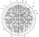
- FIG. 3 is a cross-sectional view schematically showing the flow synthesis column of the first embodiment.
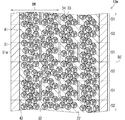
- FIG. 4 is a vertical cross-sectional view schematically showing the flow synthesis column of the first embodiment.
- the flow synthesis column 12 includes a cylinder 31.
- the cylinder 31 has an in-cylinder space 41.
- the cylinder 31 is a cylinder.
- the in-cylinder space 41 is an in-cylinder space.
- the cylinder 31 may be a cylinder other than a cylinder.
- the in-cylinder space 41 may be an in-cylinder space other than the in-cylinder space.
- the cylinder 31 may be a square cylinder.
- the in-cylinder space 41 may be a square in-cylinder space.
- the temperature of the outer peripheral surface 31a of the cylinder 31 is adjusted by the temperature controller 13.
- the flow synthesis column 12 includes a wall 32.
- the wall 32 divides the in-cylinder space 41 into a plurality of cells 42.
- the plurality of cells 42 extend in the axial direction DZ of the cylinder 31.
- the plurality of cells 42 are arranged in a direction perpendicular to the axial direction DZ.
- the plurality of cells 42 are preferably evenly arranged.
- the wall 32 divides the in-cylinder space 41 in a grid pattern.
- the wall 32 may partition the in-cylinder space 41 in a non-grid pattern.
- the wall 32 may partition the in-cylinder space 41 in a honeycomb shape.
- the wall 32 is continuous from the cylinder 31.
- the flow synthesis column 12 includes a catalyst 33 and a carrier 34.
- the catalyst 33 is exposed inside each of the plurality of cells 42.
- the catalyst 33 is a catalyst that accelerates the reaction rate of a chemical reaction in which a plurality of reactants 21 are reacted to synthesize a product 23.
- the catalyst 33 is supported on the surface of the carrier 34 inside each of the plurality of cells 42.
- the carrier 34 is arranged inside each of the plurality of cells 42.
- the carrier 34 carries the catalyst 33.
- the carrier 34 has a spherical shape.
- the carrier 34 is made of silica, polymer, alumina or the like.
- the liquid 22 is made to flow into the inflow port which is one end of the in-cylinder space 41.
- the inflowed liquid 22 is flowed into the in-cylinder space 41.
- the flowed liquid 22 is discharged from the outlet which is the other end of the in-cylinder space 41.
- the liquid 22 is flowed into the in-cylinder space 41, it is flowed into each of the plurality of cells 42.
- the liquid 22 comes into contact with the catalyst 33 arranged inside each of the plurality of cells 42.
- the reaction rate of the above-mentioned chemical reaction becomes faster.
- the radial peripheral portion of the tubular space 41 is moved to the radial central portion of the tubular space 41.
- Heat H can be efficiently transferred toward the surface. Therefore, the wall 32 can function as a good thermalization structure, and the flow synthesis column 12 can function as a good heat exchanger.
- the temperature distribution of the in-cylinder space 41 can be made uniform in the radial DR.
- the distribution of the reaction rate of the chemical reaction in the in-cylinder space 41 can be made uniform in the radial DR.
- the temperature of the in-cylinder space 41 can be brought close to the temperature suitable for the above-mentioned chemical reaction. Thereby, the reaction rate of the above-mentioned chemical reaction can be increased.
- the yield of product 23 can be increased.
- the amount of by-products produced can be suppressed.
- the wall 32 has physical characteristics and mechanical properties suitable for exerting this advantage.
- the wall 32 is preferably made of a material having a high heat transfer coefficient and a low specific heat from the viewpoint of physical characteristics. Further, from the viewpoint of mechanical properties, the wall 32 has a structure having a wide heat exchange area without obstructing the flow of the liquid 22 and increasing the pressure loss when the liquid 22 flows through each of the plurality of cells 42. It is made of a material that has high corrosion resistance.
- the wall 32 is made of, for example, ceramics. Ceramics are silicon carbide, alumina, aluminum nitride and the like.
- the carrier 34 is arranged inside each of the plurality of cells 42, the liquid 22 flows between the carriers 34 and the flow of the liquid 22 is disturbed. Therefore, the chance of contact between the plurality of reactants 21 and the catalyst 33 can be increased. Thereby, the above-mentioned chemical reaction can be further advanced.
- the carrier 34 carrying the catalyst 33 is arranged inside each of the plurality of cells 42, the specific surface area of the catalyst 33 becomes large. Therefore, the chance of contact between the plurality of reactants 21 and the catalyst 33 can be increased. Thereby, the above-mentioned chemical reaction can be further advanced.
- the in-cylinder space 41 is partitioned by the wall 32 and the carrier 34 is arranged inside each of the plurality of cells 42, the liquid 22 flows between the carriers 34 and the flow of the liquid 22 is disturbed. Therefore, the chance of contact between the liquid 22 and the wall 32 can be increased. Therefore, the frequency of heat exchange between the liquid 22 and the wall 32 can be increased. As a result, heat can be efficiently transferred to the radial DR via the wall 32.
- the catalyst 33 When the catalyst 33 is exposed inside each of the plurality of cells 42, the catalyst 33 can be cleaned by flowing a cleaning agent such as nitric acid or hydrochloric acid into each of the plurality of cells 42. Therefore, it is possible to suppress the disposal of the catalyst 33.
- a cleaning agent such as nitric acid or hydrochloric acid
- the temperature controller 13 makes the temperature distribution on the outer peripheral surface 31a of the cylinder 31 uniform in the axial direction DZ.
- the temperature controller 13 may make the temperature distribution on the outer peripheral surface 31a of the cylinder 31 uneven in the axial direction DZ.
- the temperature controller 13 has a temperature T1 on the outer peripheral surface 31a of the cylinder 31 at the position P1 in the axial direction DZ, a temperature T2 on the outer peripheral surface 31a of the cylinder 31 at the position P2 in the axial direction DZ, and a cylinder at the position P3 in the axial direction DZ.
- the temperatures T3 of the outer peripheral surface 31a of 31 may be different from each other.
- FIG. 5 shows changes in the concentrations of raw material A, raw material B, raw material C, and product depending on the distance from the inflow port in the flow synthesis column of the first embodiment.
- the progress of the chemical reaction for synthesizing the product 23 by reacting the raw material A, the raw material B, and the raw material C increases as the distance from the inflow port increases. Therefore, as shown in FIG. 5, the concentrations of the raw materials A, B, and C decrease as the distance from the inflow port increases. Further, as shown in FIG. 5, the concentration of the product 23 increases as the distance from the inflow port increases. Further, the heat generation or endothermic due to the above-mentioned chemical reaction becomes smaller as the distance from the inflow port increases. Therefore, the temperature of the outer peripheral surface 31a of the cylinder 31 suitable for advancing the above-mentioned chemical reaction changes according to the distance from the inflow port.
- the temperature of the outer peripheral surface 31a of the cylinder 31 becomes a temperature suitable for advancing the above-mentioned chemical reaction.
- the temperature of the outer peripheral surface 31a of the cylinder 31 is adjusted in this way.
- FIG. 6 is a vertical cross-sectional view schematically showing a flow synthesis column of the first modification of the first embodiment.
- the flow synthesis column 12m of the first modification of the first embodiment shown in FIG. 6 can replace the flow synthesis column 12 of the first embodiment shown in FIGS. 2, 3 and 4. ..
- the flow synthesis column 12m is different from the flow synthesis column 12 in the points described below. Regarding points not described below, the same configuration as that adopted in the flow synthesis column 12 is also adopted in the flow synthesis column 12m.
- the wall 32 is provided in the entire axial direction DZ.
- the wall 32 is provided in the first section S1 in the axial direction DZ and is arranged alternately with the first section S1. It is not provided in the second section S2 in the axial direction DZ.
- the liquids 22 flowed into the plurality of cells 42 in the first section S1 are mixed and stirred in the second section S2 following the first section S1.
- the concentration difference caused by the minute reaction rate difference in the plurality of cells 42 caused by the temperature difference inside the plurality of cells 42 can be eliminated, and the yield can be further improved.
- FIG. 7 is a cross-sectional view schematically showing a flow synthesis column of the second modification of the first embodiment.
- FIG. 8 is a cross-sectional view schematically showing a flow synthesis column of a third modification of the first embodiment.
- FIG. 9 is a cross-sectional view schematically showing a flow synthesis column of the fourth modification of the first embodiment.
- FIG. 7 shows the flow synthesis column 12A of the second modification of the first embodiment shown in FIG. 7, the flow synthesis column 12B of the third modification of the first embodiment shown in FIG. 8, and FIG.
- the flow synthesis column 12C of the fourth modification of the first embodiment can replace the flow synthesis column 12 of the first embodiment shown in FIGS. 2, 3 and 4.
- the flow synthesis columns 12A, 12B and 12C are different from the flow synthesis columns 12 in the following points. Regarding points not described below, the same configuration as that adopted in the flow synthesis column 12 is also adopted in the flow synthesis columns 12A, 12B and 12C.
- the catalyst 33 exposed inside each of the plurality of cells 42 is the carrier 34 inside each of the plurality of cells 42. It is supported on the surface.
- the catalyst 33 exposed inside each of the plurality of cells 42 is supported on the surface of the cylinder 31 and / or the wall 32. It constitutes a catalyst layer.
- the cylinder 31 and / or the wall 32 includes a base material 50 and a catalyst 51 dispersed in the base material 50, and has a plurality of cells 42.
- the catalyst 33 exposed inside each is a part of the catalyst 51.
- the cylinder 31 and / or the wall 32 constituting the flow synthesis column 12B can be manufactured through a step of mixing the catalyst 51 with the base material 50 to obtain a mixture and molding the obtained mixture.
- the cylinder 31 and / or the wall 32 is composed of the catalyst 51, and the catalyst 33 exposed inside each of the plurality of cells 42 is the catalyst 51. Is part of.
- the cylinder 31 and / or the wall 32 constituting the flow synthesis column 12C can be manufactured through a step of molding a catalyst.
- the flow synthesis column 12A has an advantage that the amount of the catalyst 33 can be reduced and the entire catalyst 33 can be exposed inside each of the plurality of cells 42 as compared with the flow synthesis columns 12B and 12C.
- the flow synthesis columns 12B and 12C can eliminate the catalyst layer, improve the density of the cells 42 per unit area, and separate the adjacent cells 42 from the partition walls, as compared with the flow synthesis columns 12A. It has the advantage that the thickness can be reduced.
- Example 2 Comparison by simulation In Example 1, the in-cylinder space 41 when organic synthesis was performed inside the flow synthesis column 12 provided with the cylinder 31 having a thermal conductivity of 160 W / m ⁇ K and the wall 32. The temperature distribution was analyzed by simulation. The thermal conductivity of 160 W / m ⁇ K corresponds to the thermal conductivity of silicon carbide.
- Example 2 the temperature distribution of the in-cylinder space 41 when organic synthesis is performed inside the flow synthesis column 12 including the cylinder 31 having a thermal conductivity of 30 W / m ⁇ K and the wall 32 is simulated. Analyzed. The thermal conductivity of 30 W / m ⁇ K corresponds to the thermal conductivity of alumina.
- FIG. 10 is a vertical cross-sectional view schematically showing the flow synthesis column of Comparative Example 1.
- the flow synthesis column 92 of Comparative Example 1 shown in FIG. 10 is different from the flow synthesis column 12 of the first embodiment shown in FIGS. 2, 3 and 4 in that the wall 32 is not provided. ..
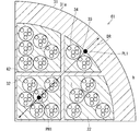
- FIG. 11 is a diagram schematically illustrating the models used in the simulations of Examples 1 and 2.
- a model conforming to the model described with reference to FIG. 11 was used.
- the temperature distribution of the fan-shaped region 61 which occupies 1/4 of the two-dimensional cross section of the flow synthesis column 12 perpendicular to the axial direction DZ and has a central angle of 90 ° is used. Analyzed. Further, in the simulation, the temperature distribution of the fan-shaped region 61 in the steady state when the heat generated by the above-mentioned chemical reaction in the fan-shaped region 61 was uniform and the outer peripheral surface 31a of the cylinder 31 was cooled to 20 ° C. was analyzed. Moreover, in the simulation, the influence of the catalyst 33 was not considered in order to facilitate the analysis.
- the diameter of the cylinder 31 is 10 mm
- the heat transfer coefficient h outside the outer peripheral surface 31a of the cylinder 31 is 100 W / m 2 ⁇ K
- the thermal conductivity ⁇ of the object arranged in the cylinder inner space 41 is uniform. It was set to 1 W / m ⁇ K
- the calorific value Q in the in-cylinder space 41 was set to 3.62 ⁇ 10 6 W / m 2 .
- the heat transfer coefficient h of 100 W / m 2 ⁇ K is the minimum value of the heat transfer coefficient when the liquid is forcibly convected.
- the thermal conductivity ⁇ of 1 W / m ⁇ K is the product of the thermal conductivity ⁇ 1 of the carrier 34 and the ratio ⁇ 1 of the area occupied by the carrier 34 ⁇ 1 ⁇ ⁇ 1, and the thermal conductivity ⁇ 2 of the liquid 22 and the liquid. 22 the product ⁇ 2 ⁇ ⁇ 2 between the ratio epsilon 2 of the area occupied by the sum ⁇ 1 ⁇ ⁇ 1 + ⁇ 2 ⁇ ⁇ 2 of.
- the calorific value Q of 3.62 ⁇ 10 6 W / m 2 is the calorific value when the heat generated in the fan-shaped region 61 is up to 70 ° C. The temperature of 70 ° C. was determined from the typical heat generation in organic synthesis.
- Table 1 shows the maximum temperature and the minimum temperature indicating the temperatures of the maximum temperature point PH1 and the minimum temperature point PL1 shown in FIG. 3 in Examples 1 and 2, respectively.
- Table 1 shows the temperature difference indicating the difference between the maximum temperature and the minimum temperature.
- Table 1 shows the maximum temperature and the minimum temperature indicating the temperatures of the maximum temperature point PH2 and the minimum temperature point PL2 shown in FIG. 10 in Comparative Example 1, respectively.
- Table 1 shows the temperature difference indicating the difference between the maximum temperature and the minimum temperature.
Landscapes
- Chemical & Material Sciences (AREA)
- Organic Chemistry (AREA)
- Chemical Kinetics & Catalysis (AREA)
- Organic Low-Molecular-Weight Compounds And Preparation Thereof (AREA)
- Physical Or Chemical Processes And Apparatus (AREA)
Abstract
径方向について筒内空間の温度の分布を均一にすることができるフロー合成用カラムを提供する。フロー合成用カラムは、筒、壁及び触媒を備える。筒は、筒内空間を有する。壁は、筒内空間を筒の軸方向に伸びる複数のセルに区画する。触媒は、複数のセルの各々の内部に露出する。
Description
本発明は、フロー合成用カラム及びフロー合成装置に関する。
複数の反応物から生成物を合成する方法は、バッチ合成により合成する方法及びフロー合成により合成する方法に大別される。
バッチ合成により複数の反応物から生成物が合成される際には、複数の反応物を含む液体、及び触媒が反応釜に入れられる。複数の反応物は、反応釜の内部で反応させられる。これにより、生成物が生成し、多くの場合は、副生成物も生成する。複数の反応物が反応させられる際には、多くの場合は、反応釜に蒸気、冷水又は冷媒が通されて液体が加熱又は冷却される。また、複数の反応物が触媒に接触させられる。生成物、副生成物及び触媒を含む液体は、反応釜から出される。生成物、副生成物及び触媒は、濾過、単離等により分離される。これにより、目的とする生成物が得られる。分離された触媒は、多くの場合は、廃棄される。
フロー合成により複数の反応物から生成物が合成される際には、複数の反応物を含む液体がフロー合成用カラムに流入させられる。複数の反応物は、フロー合成用カラムの内部で反応させられる。これにより、生成物が生成し、多くの場合は、副生成物も生成する。複数の反応物が反応させられる際には、多くの場合は、フロー合成用カラムの外周面が加熱又は冷却されて液体が加熱又は冷却される。また、複数の反応物がフロー合成用カラムに備えられる担体に担持される触媒に接触させられる。生成物及び副生成物を含む液体は、フロー合成用カラムから流出させられる。生成物及び副生成物は、濾過、単離等により分離される。これにより、目的とする生成物が得られる。
フロー合成は、バッチ合成と比較して、触媒を分離するプロセスを省略することができるという利点を有する。また、フロー合成は、バッチ合成と比較して、触媒の廃棄を抑制することができるという利点を有する。また、フロー合成は、バッチ合成と比較して、生成物を連続的に生成させることができるという利点を有する。また、フロー合成は、バッチ合成と比較して、液体を加熱又は冷却するエネルギーのコストを抑制することができるという利点を有する。
特許文献1は、連続的フロー多段階合成装置を開示する(段落0029)。連続的フロー多段階合成装置は、固相担体を充填したカラムを備える(段落0029)。カラムは、恒温槽により温度調整ができる(段落0025)。
フロー合成用カラムにおいては、その径方向の熱の伝達は、担体間の熱の伝達及び液体による熱の伝達に依存する。しかし、多くの場合は、担体間の熱の伝達及び液体による熱の伝熱は、十分でない。このため、フロー合成用カラムにおいては、その径方向についてその筒内空間の温度の分布を均一にすることが困難である。例えば、複数の反応物から生成物を合成する反応が発熱反応である場合及びフロー合成用カラムの外周面が冷却される場合は、筒内空間の径方向中心部の温度が相対的に高くなり、筒内空間の径方向周辺部の温度が相対的に低くなる。逆に、複数の反応物から生成物を合成する反応が吸熱反応である場合及びフロー合成用カラムの外周面が加熱される場合は、筒内空間の径方向中心部の温度が相対的に低くなり、筒内空間の径方向周辺部の温度が相対的に高くなる。そして、フロー合成用カラムの径方向について筒内空間の温度の分布を均一にすることができない場合は、生成物の収率が低下し、副生成物の生成量が増加する。
本発明は、この問題に鑑みてなされた。本発明は、径方向について筒内空間の温度の分布を均一にすることができるフロー合成用カラムを提供することを目的とする。
本発明は、フロー合成用カラムに関する。
フロー合成用カラムは、筒、壁及び触媒を備える。
筒は、筒内空間を有する。
壁は、筒内空間を筒の軸方向に伸びる複数のセルに区画する。
触媒は、複数のセルの各々の内部に露出する。
本発明は、当該フロー合成用カラムを備えるフロー合成装置にも向けられる。
本発明によれば、壁により液体とフロー合成用カラムとの間の熱交換面積が広くなる。このため、壁を経由して径方向に効率よく熱を伝達することができる。
これにより、径方向について筒内空間の温度の分布を均一にすることができる。これにより、径方向について筒内空間における化学反応の反応速度の分布を均一にすることができる。
また、筒内空間の温度を化学反応に適した温度に近づけることができる。これにより、筒内空間における化学反応の反応速度を速くすることができる。
したがって、生成物の収率を高くすることができる。また、副生成物の生成量を抑制することができる。
この発明の目的、特徴、局面及び利点は、以下の詳細な説明と添付図面とによって、より明白となる。
1 第1実施形態
1.1 フロー合成装置
図1は、第1実施形態のフロー合成装置を模式的に図示する図である。
1.1 フロー合成装置
図1は、第1実施形態のフロー合成装置を模式的に図示する図である。
図1に図示されるように、第1実施形態のフロー合成装置1は、ミキサー11、フロー合成用カラム12及び温度調節器13を備える。
ミキサー11は、複数の反応物21を混合して複数の反応物21を含む液体22を生成する。また、ミキサー11は、生成した液体22をフロー合成用カラム12に流入させる。第1実施形態においては、複数の反応物21は、3種類の原料A,B及びCである。複数の反応物21が、2種類の原料又は4種類以上の原料であってもよい。液体22が、複数の反応物21以外の物質を含んでもよい。例えば、液体22が、溶媒を含んでもよい。
フロー合成用カラム12は、流入させられた液体22に含まれる複数の反応物21を互いに反応させて生成物23を合成する。フロー合成用カラム12は、合成された生成物23を含む液体を流出させる。
温度調節器13は、フロー合成用カラム12の温度を調節する。これにより、フロー合成用カラム12に流入させられた液体22の温度が、複数の反応物21を反応させて生成物23を合成する化学反応に適した温度に調節される。温度調節器13は、フロー合成用カラム12を加熱するヒータ及びフロー合成用カラム12を冷却するクーラーの少なくとも一方の機能を有する。ヒータは、電気加熱を行う電気抵抗ヒータ、蒸気、油等の熱媒を循環させて加熱を行う熱媒ヒータ等である。クーラーは、ペルチエ効果を利用して電子冷却を行う電子冷却クーラー、冷水又は冷媒を循環させて冷却を行うクーラー等である。
1.2 フロー合成用カラム
図2は、第1実施形態のフロー合成用カラムを模式的に図示する斜視図である。図3は、第1実施形態のフロー合成用カラムを模式的に図示する横断面図である。図4は、第1実施形態のフロー合成用カラムを模式的に図示する縦断面図である。
図2は、第1実施形態のフロー合成用カラムを模式的に図示する斜視図である。図3は、第1実施形態のフロー合成用カラムを模式的に図示する横断面図である。図4は、第1実施形態のフロー合成用カラムを模式的に図示する縦断面図である。
図2、図3及び図4に図示されるように、フロー合成用カラム12は、筒31を備える。図3及び図4に図示されるように、筒31は、筒内空間41を有する。第1実施形態においては、筒31は、円筒である。また、筒内空間41は、円筒内空間である。筒31が、円筒以外の筒であってもよい。また、筒内空間41が、円筒内空間以外の筒内空間であってもよい。例えば、筒31が、角筒であってもよい。また、筒内空間41が、角筒内空間であってもよい。筒31の外周面31aの温度は、温度調節器13により調整される。
図3及び図4に図示されるように、フロー合成用カラム12は、壁32を備える。
壁32は、筒内空間41を複数のセル42に区画する。複数のセル42は、筒31の軸方向DZに伸びる。複数のセル42は、軸方向DZと垂直をなす方向に配列される。複数のセル42は、望ましくは、均一に配置される。これにより、液体22が複数のセル42の各々に流された場合に液体22の流れが阻害されることを抑制することができる。これにより、液体22が複数のセル42の各々に流された際の圧力損失を減らすことができる。第1実施形態においては、壁32は、筒内空間41を格子状に区画する。壁32が、筒内空間41を非格子状に区画してもよい。例えば、壁32が、筒内空間41をハニカム状に区画してもよい。壁32は、筒31から連続している。
図3及び図4に図示されるように、フロー合成用カラム12は、触媒33及び担体34を備える。
触媒33は、複数のセル42の各々の内部に露出する。触媒33は、複数の反応物21を反応させて生成物23を合成する化学反応の反応速度を速くする触媒である。第1実施形態においては、触媒33は、複数のセル42の各々の内部において担体34の表面に担持される。
担体34は、複数のセル42の各々の内部に配置される。担体34は、触媒33を担持する。担体34は、球状の形状を有する。担体34は、シリカ、ポリマー、アルミナ等からなる。
液体22は、筒内空間41の一端である流入口に流入させられる。流入させられた液体22は、筒内空間41に流される。流された液体22は、筒内空間41の他端である流出口から流出させられる。液体22は、筒内空間41に流される際に、複数のセル42の各々に流される。これにより、液体22は、複数のセル42の各々の内部に配置される触媒33に接触する。これより、上述した化学反応の反応速度が速くなる。
1.3 壁により筒内空間を区画することの利点
壁32により筒内空間41が区画された場合は、液体22とフロー合成用カラム12との間の熱交換面積が広くなる。このため、壁32を経由して筒31の径方向DRに効率よく熱Hを伝達することができる。例えば、上述した化学反応が発熱反応である場合及び温度調節器13が筒31の外周面31aを冷却する場合は、筒内空間41の径方向中心部から筒内空間41の径方向周辺部へ向かって効率よく熱Hを伝達することができる。また、上述した化学反応が吸熱反応である場合及び温度調節器13が筒31の外周面31aを加熱する場合は、筒内空間41の径方向周辺部から筒内空間41の径方向中心部へ向かって効率よく熱Hを伝達することができる。したがって、壁32を良好な均熱化構造として機能させることができ、フロー合成用カラム12を良好な熱交換体として機能させることができる。
壁32により筒内空間41が区画された場合は、液体22とフロー合成用カラム12との間の熱交換面積が広くなる。このため、壁32を経由して筒31の径方向DRに効率よく熱Hを伝達することができる。例えば、上述した化学反応が発熱反応である場合及び温度調節器13が筒31の外周面31aを冷却する場合は、筒内空間41の径方向中心部から筒内空間41の径方向周辺部へ向かって効率よく熱Hを伝達することができる。また、上述した化学反応が吸熱反応である場合及び温度調節器13が筒31の外周面31aを加熱する場合は、筒内空間41の径方向周辺部から筒内空間41の径方向中心部へ向かって効率よく熱Hを伝達することができる。したがって、壁32を良好な均熱化構造として機能させることができ、フロー合成用カラム12を良好な熱交換体として機能させることができる。
これにより、径方向DRについて筒内空間41の温度の分布を均一にすることができる。これにより、径方向DRについて筒内空間41における化学反応の反応速度の分布を均一にすることができる。
また、筒内空間41の温度を上述した化学反応に適した温度に近づけることができる。これにより、上述した化学反応の反応速度を速くすることができる。
したがって、生成物23の収率を高くすることができる。また、副生成物の生成量を抑制することができる。
壁32は、この利点を発揮するのに適した物性値及び機械的特性を有する。壁32は、物性値の観点からは、望ましくは、高い熱伝達率及び低い比熱を有する材料からなる。また、壁32は、機械的特性の観点からは、液体22の流れを阻害せず、液体22が複数のセル42の各々を流れる際の圧力損失を増やさず、広い熱交換面積を有する構造を有し、高い耐食性を有する材料からなる。壁32は、例えば、セラミックスからなる。セラミックスは、炭化ケイ素、アルミナ、窒化アルミニウム等である。
1.4 触媒を担持する担体をセルの内部に配置することの利点
担体34が複数のセル42の各々の内部に配置された場合は、液体22が担体34に当たって液体22の流れが遅くなる。このため、複数の反応物21と触媒33との接触時間を長くすることができる。これにより、上述した化学反応をより進行させることができる。
担体34が複数のセル42の各々の内部に配置された場合は、液体22が担体34に当たって液体22の流れが遅くなる。このため、複数の反応物21と触媒33との接触時間を長くすることができる。これにより、上述した化学反応をより進行させることができる。
また、担体34が複数のセル42の各々の内部に配置された場合は、液体22が担体34の間を流れて液体22の流れが乱れる。このため、複数の反応物21と触媒33との接触機会を増やすことができる。これにより、上述した化学反応をより進行させることができる。
また、触媒33を担持する担体34が複数のセル42の各々の内部に配置された場合は、触媒33の比表面積が広くなる。このため、複数の反応物21と触媒33との接触機会を増やすことができる。これにより、上述した化学反応をより進行させることができる。
また、壁32により筒内空間41が区画されるとともに担体34が複数のセル42の各々の内部に配置された場合は、液体22が担体34の間を流れて液体22の流れが乱れる。このため、液体22と壁32との接触機会を増やすことができる。このため、液体22と壁32との間の熱交換頻度を増やすことができる。これにより、壁32を経由して径方向DRに効率よく熱を伝達することができる。
また、触媒33が複数のセル42の各々の内部に露出する場合は、硝酸、塩酸等の洗浄剤を複数のセル42の各々に流すことにより、触媒33を洗浄することができる。このため、触媒33の廃棄を抑制することができる。
1.5 温度調節器による温度の調節
温度調節器13は、軸方向DZについて筒31の外周面31aの温度の分布を均一にする。
温度調節器13は、軸方向DZについて筒31の外周面31aの温度の分布を均一にする。
温度調節器13が、軸方向DZについて筒31の外周面31aの温度の分布を不均一にしてもよい。例えば、温度調節器13が、軸方向DZの位置P1における筒31の外周面31aの温度T1、軸方向DZの位置P2における筒31の外周面31aの温度T2及び軸方向DZの位置P3における筒31の外周面31aの温度T3を互いに異ならせてもよい。
図5は、第1実施形態のフロー合成用カラムにおける、流入口からの距離による原料A、原料B、原料C及び生成物の濃度の変化を示す。
原料A、原料B及び原料Cを反応させて生成物23を合成する化学反応の進行度は、流入口からの距離が長くなるほど大きくなる。このため、図5に示されるように、原料A,B及びCの濃度は、流入口からの距離が長くなるほど低くなる。また、図5に示されるように、生成物23の濃度は、流入口からの距離が長くなるほど高くなる。また、上述した化学反応による発熱又は吸熱は、流入口からの距離が長くなるほど小さくなる。このため、上述した化学反応を進行させるのに適する筒31の外周面31aの温度は、流入口からの距離に応じて変化する。このため、温度調節器13は、筒31の外周面31aの温度の分布を不均一にする場合は、筒31の外周面31aの温度が上述した化学反応を進行させるのに適した温度となるように筒31の外周面31aの温度を調節する。
1.6 変形例
図6は、第1実施形態の第1変形例のフロー合成用カラムを模式的に図示する縦断面図である。
図6は、第1実施形態の第1変形例のフロー合成用カラムを模式的に図示する縦断面図である。
図6に図示される第1実施形態の第1変形例のフロー合成用カラム12mは、図2、図3及び図4に図示される第1実施形態のフロー合成用カラム12を置き換えることができる。フロー合成用カラム12mは、下述する点でフロー合成用カラム12と相違する。下述されない点については、フロー合成用カラム12において採用される構成と同様の構成がフロー合成用カラム12mにおいても採用される。
図4に図示されるように、フロー合成用カラム12においては、壁32が、軸方向DZの全体に設けられる。これに対して、図6に図示されるように、フロー合成用カラム12mにおいては、壁32が、軸方向DZの第1の区間S1に設けられ、第1の区間S1と交互に配置される軸方向DZの第2の区間S2に設けられない。これにより、第1の区間S1において複数のセル42に流された液体22が、第1の区間S1に続く第2の区間S2において混合されて攪拌される。これにより、上述した化学反応をより進行させることができる。また、複数のセル42の内部の温度差によって生じる複数のセル42における微小な反応速度差に起因する濃度差を解消することができ、収率をさらに向上することができる。
図7は、第1実施形態の第2変形例のフロー合成用カラムを模式的に図示する横断面図である。図8は、第1実施形態の第3変形例のフロー合成用カラムを模式的に図示する横断面図である。図9は、第1実施形態の第4変形例のフロー合成用カラムを模式的に図示する横断面図である。
図7に図示される第1実施形態の第2変形例のフロー合成用カラム12A、図8に図示される第1実施形態の第3変形例のフロー合成用カラム12B及び図9に図示される第1実施形態の第4変形例のフロー合成用カラム12Cは、図2、図3及び図4に図示される第1実施形態のフロー合成用カラム12を置き換えることができる。フロー合成用カラム12A,12B及び12Cは、下述する点でフロー合成用カラム12と相違する。下述されない点については、フロー合成用カラム12において採用される構成と同様の構成がフロー合成用カラム12A,12B及び12Cにおいても採用される。
図2、図3及び図4に図示されるように、フロー合成用カラム12においては、複数のセル42の各々の内部に露出する触媒33は、複数のセル42の各々の内部において担体34の表面に担持される。
これに対して、図7に図示されるように、フロー合成用カラム12Aにおいては、複数のセル42の各々の内部に露出する触媒33は、円筒31及び/又は壁32の表面に担持され、触媒層を構成する。
また、図8に図示されるように、フロー合成用カラム12Bにおいては、円筒31及び/又は壁32は、母材50及び母材50に分散している触媒51を備え、複数のセル42の各々の内部に露出する触媒33は、触媒51の一部である。フロー合成用カラム12Bを構成する円筒31及び/又は壁32は、触媒51を母材50に混合して混合物を得、得た混合物を成型する工程を経て製造することができる。
また、図9に図示されるように、フロー合成用カラム12Cにおいては、円筒31及び/又は壁32は、触媒51からなり、複数のセル42の各々の内部に露出する触媒33は、触媒51の一部である。フロー合成用カラム12Cを構成する円筒31及び/又は壁32は、触媒を成型する工程を経て製造することができる。
フロー合成用カラム12Aは、フロー合成用カラム12B及び12Cと比較して、触媒33の量を減らすことができ、触媒33の全体を複数のセル42の各々の内部に露出させることができるという利点を有する。フロー合成用カラム12B及び12Cは、フロー合成用カラム12Aと比較して、触媒層をなくすことができ、単位面積あたりのセル42の密度を向上することができ、隣接するセル42を隔てる隔壁の厚さを薄くすることができるという利点を有する。
1.7 シミュレーションによる比較
実施例1においては、160W/m・Kの熱伝導率を有する筒31及び壁32を備えるフロー合成用カラム12の内部で有機合成を行った場合の筒内空間41の温度の分布をシミュレーションにより解析した。160W/m・Kの熱伝導率は、炭化ケイ素の熱伝導率に相当する。
実施例1においては、160W/m・Kの熱伝導率を有する筒31及び壁32を備えるフロー合成用カラム12の内部で有機合成を行った場合の筒内空間41の温度の分布をシミュレーションにより解析した。160W/m・Kの熱伝導率は、炭化ケイ素の熱伝導率に相当する。
実施例2においては、30W/m・Kの熱伝導率を有する筒31及び壁32を備えるフロー合成用カラム12の内部で有機合成を行った場合の筒内空間41の温度の分布をシミュレーションにより解析した。30W/m・Kの熱伝導率は、アルミナの熱伝導率に相当する。
図10は、比較例1のフロー合成用カラムを模式的に図示する縦断面図である。
図10に図示される比較例1のフロー合成用カラム92は、壁32を備えない点で、図2、図3及び図4に図示される第1実施形態のフロー合成用カラム12と相違する。
比較例1においては、30W/m・Kの熱伝導率を有する筒31を備えるが壁32を備えないフロー合成用カラム92の内部で有機合成を行った場合の筒内空間41の温度の分布をシミュレーションにより解析した。30W/m・Kの熱伝導率は、ステンレス鋼の熱伝導率に相当する。
図11は、実施例1及び2のシミュレーションに用いたモデルを模式的に説明する図である。比較例1のシミュレーションにも、図11により説明されるモデルに即したモデルを用いた。
図11に説明されるように、シミュレーションにおいては、軸方向DZと垂直をなすフロー合成用カラム12の2次元断面の1/4を占め90°の中心角を有する扇形領域61の温度の分布を解析した。また、シミュレーションにおいては、扇形領域61における上述した化学反応による発熱が均一であり筒31の外周面31aが20℃に冷却される場合の定常状態における扇形領域61の温度の分布を解析した。また、シミュレーションにおいては、解析を容易にするために、触媒33の影響は考慮しなかった。また、筒31の直径を10mmとし、筒31の外周面31aの外側の熱伝達率hを100W/m2・Kとし、筒内空間41に配置された物の熱伝導率λを一様の1W/m・Kとし、筒内空間41における発熱量Qを3.62×106W/m2とした。100W/m2・Kという熱伝達率hは、液体を強制対流させた場合の熱伝達率の最低値である。1W/m・Kという熱伝導率λは、担体34の熱伝導率λ1と担体34が占める面積の割合ε1との積λ1×ε1と、液体22の熱伝達率λ2と液体22が占める面積の割合ε2との積λ2×ε2と、の和λ1×ε1+λ2×ε2である。3.62×106W/m2という発熱量Qは、扇形領域61における発熱が70℃までの発熱である場合の発熱量である。70℃という温度は、有機合成における典型的な発熱から決めた。
実施例1及び2における、図3に図示される最高温度点PH1及び最低温度点PL1の温度をそれぞれ示す最高温度及び最低温度を表1に示す。また、当該最高温度と当該最低温度との差を示す温度差を表1に示す。
比較例1における、図10に図示される最高温度点PH2及び最低温度点PL2の温度をそれぞれ示す最高温度及び最低温度を表1に示す。また、当該最高温度と当該最低温度との差を示す温度差を表1に示す。
表1からは、壁32を備えるフロー合成用カラム12の内部で有機合成を行った場合は、壁32を備えないフロー合成用カラム92の内部で有機合成を行った場合と比較して、温度差を大幅に小さくすることができることを理解することができる。したがって、壁32は、筒内空間41の温度の分布を均一にすることに寄与することを理解することができる。

この発明は詳細に説明されたが、上記した説明は、すべての局面において、例示であって、この発明がそれに限定されるものではない。例示されていない無数の変形例が、この発明の範囲から外れることなく想定され得るものと解される。
1 フロー合成装置
11 ミキサー
12 フロー合成用カラム
12m フロー合成用カラム
12A フロー合成用カラム
12B フロー合成用カラム
12C フロー合成用カラム
13 温度調節器
31 筒
32 壁
33 触媒
34 担体
41 筒内空間
42 複数のセル
50 母材
51 触媒
11 ミキサー
12 フロー合成用カラム
12m フロー合成用カラム
12A フロー合成用カラム
12B フロー合成用カラム
12C フロー合成用カラム
13 温度調節器
31 筒
32 壁
33 触媒
34 担体
41 筒内空間
42 複数のセル
50 母材
51 触媒
Claims (11)
- 筒内空間を有する筒と、
前記筒内空間を前記筒の軸方向に伸びる複数のセルに区画する壁と、
前記複数のセルの各々の内部に露出する触媒と、
を備えるフロー合成用カラム。 - 前記複数のセルの各々の内部に露出する触媒は、前記複数のセルの各々の内部において担持される
請求項1のフロー合成用カラム。 - 前記複数のセルの各々の内部に配置される担体を備え、
前記複数のセルの各々の内部に露出する触媒は、前記担体の表面に担持される
請求項2のフロー合成用カラム。 - 前記複数のセルの各々の内部に露出する触媒は、前記筒及び/又は前記壁の表面に担持される
請求項2のフロー合成用カラム。 - 前記筒及び/又は前記壁は、母材及び前記母材に分散している触媒を備え、
前記複数のセルの各々の内部に露出する触媒は、前記母材に分散している触媒の一部である
請求項1のフロー合成用カラム。 - 前記筒及び/又は前記壁は、触媒からなり、
前記複数のセルの各々の内部に露出する触媒は、前記筒及び/又は前記壁を構成する触媒の一部である
請求項1のフロー合成用カラム。 - 前記壁は、前記軸方向の第1の区間に設けられ、前記第1の区間と交互に配置される前記軸方向の第2の区間に設けられない
請求項1から6までのいずれかのフロー合成用カラム。 - 複数の反応物を混合して前記複数の反応物を含む液体を生成するミキサーと、
請求項1から7までのいずれかのフロー合成用カラムであり、前記液体が流入させられ、前記複数の反応物を反応させて生成物を合成するフロー合成用カラムと、
を備え、
前記複数のセルの各々の内部に露出する触媒は、前記複数の反応物を反応させて前記生成物を合成する化学反応の反応速度を速くする触媒である
フロー合成装置。 - 前記筒は、外周面を有し、
前記外周面の温度を調節する温度調節器を備える
請求項8のフロー合成装置。 - 前記温度調節器は、前記軸方向について前記外周面の温度の分布を均一にする
請求項9のフロー合成装置。 - 前記温度調節器は、前記軸方向について前記外周面の温度の分布を不均一にする
請求項9のフロー合成装置。
Priority Applications (2)
| Application Number | Priority Date | Filing Date | Title |
|---|---|---|---|
| JP2022519872A JPWO2021224980A1 (ja) | 2020-05-08 | 2020-05-08 | |
| PCT/JP2020/018630 WO2021224980A1 (ja) | 2020-05-08 | 2020-05-08 | フロー合成用カラム及びフロー合成装置 |
Applications Claiming Priority (1)
| Application Number | Priority Date | Filing Date | Title |
|---|---|---|---|
| PCT/JP2020/018630 WO2021224980A1 (ja) | 2020-05-08 | 2020-05-08 | フロー合成用カラム及びフロー合成装置 |
Publications (1)
| Publication Number | Publication Date |
|---|---|
| WO2021224980A1 true WO2021224980A1 (ja) | 2021-11-11 |
Family
ID=78467955
Family Applications (1)
| Application Number | Title | Priority Date | Filing Date |
|---|---|---|---|
| PCT/JP2020/018630 Ceased WO2021224980A1 (ja) | 2020-05-08 | 2020-05-08 | フロー合成用カラム及びフロー合成装置 |
Country Status (2)
| Country | Link |
|---|---|
| JP (1) | JPWO2021224980A1 (ja) |
| WO (1) | WO2021224980A1 (ja) |
Citations (6)
| Publication number | Priority date | Publication date | Assignee | Title |
|---|---|---|---|---|
| US20030012711A1 (en) * | 1999-11-17 | 2003-01-16 | Conoco Inc. | Honeycomb monolith catalyst support for catalytic distillation reactor |
| JP2007500601A (ja) * | 2003-07-30 | 2007-01-18 | コーニング インコーポレイテッド | 化学および熱用途のための金属ハニカム基体 |
| JP2012501240A (ja) * | 2008-06-27 | 2012-01-19 | ユミコア・アクチエンゲゼルシャフト・ウント・コムパニー・コマンディットゲゼルシャフト | 高い選択率及び収率で不均一系触媒反応を実施するための方法 |
| JP2013533369A (ja) * | 2010-08-09 | 2013-08-22 | ビーエーエスエフ ソシエタス・ヨーロピア | ポリエーテルアルコールを製造する方法 |
| JP2015172025A (ja) * | 2014-03-11 | 2015-10-01 | 東京化成工業株式会社 | 連続的フロー多段階反応による医薬品の製造方法 |
| JP2018015695A (ja) * | 2016-07-26 | 2018-02-01 | ニッポン高度紙工業株式会社 | 管状の触媒システムおよびそれを使用した化学反応装置、管状の触媒システムの製造方法 |
Family Cites Families (1)
| Publication number | Priority date | Publication date | Assignee | Title |
|---|---|---|---|---|
| US7316804B2 (en) * | 2001-08-02 | 2008-01-08 | Ineos Usa Llc | Flow reactors for chemical conversions with heterogeneous catalysts |
-
2020
- 2020-05-08 WO PCT/JP2020/018630 patent/WO2021224980A1/ja not_active Ceased
- 2020-05-08 JP JP2022519872A patent/JPWO2021224980A1/ja active Pending
Patent Citations (6)
| Publication number | Priority date | Publication date | Assignee | Title |
|---|---|---|---|---|
| US20030012711A1 (en) * | 1999-11-17 | 2003-01-16 | Conoco Inc. | Honeycomb monolith catalyst support for catalytic distillation reactor |
| JP2007500601A (ja) * | 2003-07-30 | 2007-01-18 | コーニング インコーポレイテッド | 化学および熱用途のための金属ハニカム基体 |
| JP2012501240A (ja) * | 2008-06-27 | 2012-01-19 | ユミコア・アクチエンゲゼルシャフト・ウント・コムパニー・コマンディットゲゼルシャフト | 高い選択率及び収率で不均一系触媒反応を実施するための方法 |
| JP2013533369A (ja) * | 2010-08-09 | 2013-08-22 | ビーエーエスエフ ソシエタス・ヨーロピア | ポリエーテルアルコールを製造する方法 |
| JP2015172025A (ja) * | 2014-03-11 | 2015-10-01 | 東京化成工業株式会社 | 連続的フロー多段階反応による医薬品の製造方法 |
| JP2018015695A (ja) * | 2016-07-26 | 2018-02-01 | ニッポン高度紙工業株式会社 | 管状の触媒システムおよびそれを使用した化学反応装置、管状の触媒システムの製造方法 |
Also Published As
| Publication number | Publication date |
|---|---|
| JPWO2021224980A1 (ja) | 2021-11-11 |
Similar Documents
| Publication | Publication Date | Title |
|---|---|---|
| Nijemeisland et al. | Catalyst design by CFD for heat transfer and reaction in steam reforming | |
| US7033553B2 (en) | Chemical reactor | |
| EP1251951B2 (en) | Chemical reactor with heat exchanger | |
| Evans et al. | Effects of boundary conditions on the flow and heat transfer in a rotating disk chemical vapor deposition reactor | |
| EP2900364B1 (en) | Weir quench and processes incorporating the same | |
| Luo et al. | Constructal approach and multi-scale components | |
| Goyal | Process intensification using microwave heated multiphase reactors | |
| Mohammad et al. | Scale-up of high-pressure FT synthesis in 3D printed stainless steel microchannel microreactors: Experiments and modeling | |
| Cybulski et al. | Monolithic reactors for fine chemicals industries: a comparative analysis of a monolithic reactor and a mechanically agitated slurry reactor | |
| Grande et al. | Production of customized reactors by 3D printing for corrosive and exothermic reactions | |
| CN110773102B (zh) | 反应器、制造反应器的方法以及制造产物的方法 | |
| Jiang et al. | Numerical investigation of flow and heat transfer in a novel configuration multi-tubular fixed bed reactor for propylene to acrolein process | |
| Haase et al. | Gas–liquid flow regime prediction in Minichannels: a dimensionless, universally applicable approach | |
| CN113203302A (zh) | 一种强化两种微流体混合的微通道换热装置 | |
| Cybulski et al. | Gas-particle heat transfer coefficients in packed beds at low Reynolds numbers | |
| CN204395961U (zh) | 一种具有内置换热挡板的聚甲氧基二甲醚搅拌式反应器 | |
| Xu et al. | Experimental investigation on hydrogen production by methanol steam reforming in a novel fractal microreactor | |
| Edouard et al. | The effective thermal properties of solid foam beds: Experimental and estimated temperature profiles | |
| CN102413918B (zh) | 蜂窝体反应器最优化通道尺寸设定 | |
| Díaz et al. | A predictive model for flow distribution in dual-zone packed bed reactors | |
| Wang et al. | Continuous production of 3, 5, 5-trimethylhexanoyl chloride and CFD simulations of single-phase flow in an advanced-flow reactor | |
| KR100997570B1 (ko) | 다중 중합 반응기 | |
| CN112654424B (zh) | 具有挡板的间歇式反应器 | |
| Limper et al. | Reactor design via scan line patterning: An implicit approach to create scalable microstructured parts in selective laser melting | |
| Sturm et al. | Microwave reactor concepts: From resonant cavities to traveling fields |
Legal Events
| Date | Code | Title | Description |
|---|---|---|---|
| 121 | Ep: the epo has been informed by wipo that ep was designated in this application |
Ref document number: 20934452 Country of ref document: EP Kind code of ref document: A1 |
|
| ENP | Entry into the national phase |
Ref document number: 2022519872 Country of ref document: JP Kind code of ref document: A |
|
| NENP | Non-entry into the national phase |
Ref country code: DE |
|
| 122 | Ep: pct application non-entry in european phase |
Ref document number: 20934452 Country of ref document: EP Kind code of ref document: A1 |