WO2021221017A1 - 内視鏡システム - Google Patents
内視鏡システム Download PDFInfo
- Publication number
- WO2021221017A1 WO2021221017A1 PCT/JP2021/016660 JP2021016660W WO2021221017A1 WO 2021221017 A1 WO2021221017 A1 WO 2021221017A1 JP 2021016660 W JP2021016660 W JP 2021016660W WO 2021221017 A1 WO2021221017 A1 WO 2021221017A1
- Authority
- WO
- WIPO (PCT)
- Prior art keywords
- image
- feature portion
- endoscope
- dimensional information
- information
- Prior art date
- Legal status (The legal status is an assumption and is not a legal conclusion. Google has not performed a legal analysis and makes no representation as to the accuracy of the status listed.)
- Ceased
Links
Images


Classifications
-
- A—HUMAN NECESSITIES
- A61—MEDICAL OR VETERINARY SCIENCE; HYGIENE
- A61B—DIAGNOSIS; SURGERY; IDENTIFICATION
- A61B1/00—Instruments for performing medical examinations of the interior of cavities or tubes of the body by visual or photographical inspection, e.g. endoscopes; Illuminating arrangements therefor
- A61B1/00163—Optical arrangements
- A61B1/00194—Optical arrangements adapted for three-dimensional imaging
-
- A—HUMAN NECESSITIES
- A61—MEDICAL OR VETERINARY SCIENCE; HYGIENE
- A61B—DIAGNOSIS; SURGERY; IDENTIFICATION
- A61B1/00—Instruments for performing medical examinations of the interior of cavities or tubes of the body by visual or photographical inspection, e.g. endoscopes; Illuminating arrangements therefor
- A61B1/00002—Operational features of endoscopes
- A61B1/00004—Operational features of endoscopes characterised by electronic signal processing
- A61B1/00009—Operational features of endoscopes characterised by electronic signal processing of image signals during a use of endoscope
- A61B1/000094—Operational features of endoscopes characterised by electronic signal processing of image signals during a use of endoscope extracting biological structures
-
- A—HUMAN NECESSITIES
- A61—MEDICAL OR VETERINARY SCIENCE; HYGIENE
- A61B—DIAGNOSIS; SURGERY; IDENTIFICATION
- A61B1/00—Instruments for performing medical examinations of the interior of cavities or tubes of the body by visual or photographical inspection, e.g. endoscopes; Illuminating arrangements therefor
- A61B1/00002—Operational features of endoscopes
- A61B1/00004—Operational features of endoscopes characterised by electronic signal processing
- A61B1/00009—Operational features of endoscopes characterised by electronic signal processing of image signals during a use of endoscope
- A61B1/000096—Operational features of endoscopes characterised by electronic signal processing of image signals during a use of endoscope using artificial intelligence
-
- A—HUMAN NECESSITIES
- A61—MEDICAL OR VETERINARY SCIENCE; HYGIENE
- A61B—DIAGNOSIS; SURGERY; IDENTIFICATION
- A61B1/00—Instruments for performing medical examinations of the interior of cavities or tubes of the body by visual or photographical inspection, e.g. endoscopes; Illuminating arrangements therefor
- A61B1/00002—Operational features of endoscopes
- A61B1/00043—Operational features of endoscopes provided with output arrangements
- A61B1/00045—Display arrangement
-
- A—HUMAN NECESSITIES
- A61—MEDICAL OR VETERINARY SCIENCE; HYGIENE
- A61B—DIAGNOSIS; SURGERY; IDENTIFICATION
- A61B1/00—Instruments for performing medical examinations of the interior of cavities or tubes of the body by visual or photographical inspection, e.g. endoscopes; Illuminating arrangements therefor
- A61B1/00064—Constructional details of the endoscope body
- A61B1/00071—Insertion part of the endoscope body
- A61B1/0008—Insertion part of the endoscope body characterised by distal tip features
- A61B1/00096—Optical elements
-
- A—HUMAN NECESSITIES
- A61—MEDICAL OR VETERINARY SCIENCE; HYGIENE
- A61B—DIAGNOSIS; SURGERY; IDENTIFICATION
- A61B1/00—Instruments for performing medical examinations of the interior of cavities or tubes of the body by visual or photographical inspection, e.g. endoscopes; Illuminating arrangements therefor
- A61B1/00163—Optical arrangements
- A61B1/00174—Optical arrangements characterised by the viewing angles
- A61B1/00177—Optical arrangements characterised by the viewing angles for 90 degrees side-viewing
-
- A—HUMAN NECESSITIES
- A61—MEDICAL OR VETERINARY SCIENCE; HYGIENE
- A61B—DIAGNOSIS; SURGERY; IDENTIFICATION
- A61B1/00—Instruments for performing medical examinations of the interior of cavities or tubes of the body by visual or photographical inspection, e.g. endoscopes; Illuminating arrangements therefor
- A61B1/00163—Optical arrangements
- A61B1/00174—Optical arrangements characterised by the viewing angles
- A61B1/00181—Optical arrangements characterised by the viewing angles for multiple fixed viewing angles
-
- A—HUMAN NECESSITIES
- A61—MEDICAL OR VETERINARY SCIENCE; HYGIENE
- A61B—DIAGNOSIS; SURGERY; IDENTIFICATION
- A61B1/00—Instruments for performing medical examinations of the interior of cavities or tubes of the body by visual or photographical inspection, e.g. endoscopes; Illuminating arrangements therefor
- A61B1/00163—Optical arrangements
- A61B1/00193—Optical arrangements adapted for stereoscopic vision
-
- A—HUMAN NECESSITIES
- A61—MEDICAL OR VETERINARY SCIENCE; HYGIENE
- A61B—DIAGNOSIS; SURGERY; IDENTIFICATION
- A61B1/00—Instruments for performing medical examinations of the interior of cavities or tubes of the body by visual or photographical inspection, e.g. endoscopes; Illuminating arrangements therefor
- A61B1/04—Instruments for performing medical examinations of the interior of cavities or tubes of the body by visual or photographical inspection, e.g. endoscopes; Illuminating arrangements therefor combined with photographic or television appliances
- A61B1/05—Instruments for performing medical examinations of the interior of cavities or tubes of the body by visual or photographical inspection, e.g. endoscopes; Illuminating arrangements therefor combined with photographic or television appliances characterised by the image sensor, e.g. camera, being in the distal end portion
-
- G—PHYSICS
- G06—COMPUTING OR CALCULATING; COUNTING
- G06T—IMAGE DATA PROCESSING OR GENERATION, IN GENERAL
- G06T7/00—Image analysis
- G06T7/50—Depth or shape recovery
- G06T7/55—Depth or shape recovery from multiple images
-
- G—PHYSICS
- G06—COMPUTING OR CALCULATING; COUNTING
- G06V—IMAGE OR VIDEO RECOGNITION OR UNDERSTANDING
- G06V10/00—Arrangements for image or video recognition or understanding
- G06V10/40—Extraction of image or video features
- G06V10/56—Extraction of image or video features relating to colour
-
- H—ELECTRICITY
- H04—ELECTRIC COMMUNICATION TECHNIQUE
- H04N—PICTORIAL COMMUNICATION, e.g. TELEVISION
- H04N13/00—Stereoscopic video systems; Multi-view video systems; Details thereof
- H04N13/20—Image signal generators
- H04N13/204—Image signal generators using stereoscopic image cameras
- H04N13/207—Image signal generators using stereoscopic image cameras using a single two-dimensional [2D] image sensor
-
- H—ELECTRICITY
- H04—ELECTRIC COMMUNICATION TECHNIQUE
- H04N—PICTORIAL COMMUNICATION, e.g. TELEVISION
- H04N13/00—Stereoscopic video systems; Multi-view video systems; Details thereof
- H04N13/20—Image signal generators
- H04N13/204—Image signal generators using stereoscopic image cameras
- H04N13/243—Image signal generators using stereoscopic image cameras using three or more two-dimensional [2D] image sensors
-
- H—ELECTRICITY
- H04—ELECTRIC COMMUNICATION TECHNIQUE
- H04N—PICTORIAL COMMUNICATION, e.g. TELEVISION
- H04N13/00—Stereoscopic video systems; Multi-view video systems; Details thereof
- H04N13/20—Image signal generators
- H04N13/257—Colour aspects
-
- H—ELECTRICITY
- H04—ELECTRIC COMMUNICATION TECHNIQUE
- H04N—PICTORIAL COMMUNICATION, e.g. TELEVISION
- H04N13/00—Stereoscopic video systems; Multi-view video systems; Details thereof
- H04N13/20—Image signal generators
- H04N13/271—Image signal generators wherein the generated image signals comprise depth maps or disparity maps
-
- H—ELECTRICITY
- H04—ELECTRIC COMMUNICATION TECHNIQUE
- H04N—PICTORIAL COMMUNICATION, e.g. TELEVISION
- H04N13/00—Stereoscopic video systems; Multi-view video systems; Details thereof
- H04N13/20—Image signal generators
- H04N13/296—Synchronisation thereof; Control thereof
-
- H—ELECTRICITY
- H04—ELECTRIC COMMUNICATION TECHNIQUE
- H04N—PICTORIAL COMMUNICATION, e.g. TELEVISION
- H04N23/00—Cameras or camera modules comprising electronic image sensors; Control thereof
- H04N23/50—Constructional details
- H04N23/555—Constructional details for picking-up images in sites, inaccessible due to their dimensions or hazardous conditions, e.g. endoscopes or borescopes
-
- G—PHYSICS
- G06—COMPUTING OR CALCULATING; COUNTING
- G06T—IMAGE DATA PROCESSING OR GENERATION, IN GENERAL
- G06T2207/00—Indexing scheme for image analysis or image enhancement
- G06T2207/10—Image acquisition modality
- G06T2207/10024—Color image
-
- G—PHYSICS
- G06—COMPUTING OR CALCULATING; COUNTING
- G06T—IMAGE DATA PROCESSING OR GENERATION, IN GENERAL
- G06T2207/00—Indexing scheme for image analysis or image enhancement
- G06T2207/10—Image acquisition modality
- G06T2207/10068—Endoscopic image
-
- G—PHYSICS
- G06—COMPUTING OR CALCULATING; COUNTING
- G06T—IMAGE DATA PROCESSING OR GENERATION, IN GENERAL
- G06T2207/00—Indexing scheme for image analysis or image enhancement
- G06T2207/30—Subject of image; Context of image processing
- G06T2207/30004—Biomedical image processing
- G06T2207/30096—Tumor; Lesion
-
- H—ELECTRICITY
- H04—ELECTRIC COMMUNICATION TECHNIQUE
- H04N—PICTORIAL COMMUNICATION, e.g. TELEVISION
- H04N2213/00—Details of stereoscopic systems
- H04N2213/001—Constructional or mechanical details
Definitions
- the present invention relates to an endoscopic system that images living tissue in a body cavity.
- An endoscope is a device provided with an image sensor that is inserted into a body cavity such as a human body and images a living tissue on the inner surface of the body cavity.
- the endoscope is inserted into the large intestine, for example, and displays an image captured on a monitor in order to determine the presence or absence of an unhealthy part in a living tissue, for example, the presence or absence of a lesion part.
- an objective lens having a wide viewing angle may be used for the objective optical system of the image sensor.
- an insertion part to be inserted into an observation target a direct observation part having a field of view in the direction of the tip of the insertion part, a side view observation part having a field of view in the side surface direction of the insertion part, and a side view observation part protruding from the insertion part.
- An image acquisition unit that acquires a direct-view observation image using an endoscope having a protruding portion that forms a blind spot in the field of view and a direct-view observation unit, and acquires a side-view observation image using the side-view observation unit.
- An endoscopic system including the above is known (see JP-A-2018-57799).
- a direct-view observation image and a side-view observation image can be acquired at the same time, and a wide range of observation targets can be displayed on the display unit at the same time.
- the direct-view observation image and the side-view observation image are two-dimensional images, it is difficult for the endoscope operator to know the information on the surface unevenness of the lesion portion from the displayed captured image when the captured image is displayed. Obtaining information on surface irregularities in addition to the size of the lesion is important information for diagnosing the degree of progression of the lesion.
- an object of the present invention is to provide an endoscopic system capable of obtaining three-dimensional information of a characteristic portion such as a lesion using an image taken when a living tissue is imaged.
- One aspect of the present invention is an endoscope system including an endoscope that images a living tissue in a body cavity and an image processing unit that processes an image captured by the endoscope.
- the endoscope is An image sensor configured to image an image of living tissue, An objective lens provided in front of the light receiving surface of the image sensor and configured to form an image of a living tissue on the light receiving surface is provided.
- the image processing unit is Different imaging based on the position information of a feature portion commonly included in the captured image captured by the endoscope at at least two different imaging positions and distinguished from other portions.
- a three-dimensional expansion processing unit configured to expand the two-dimensional information of the image of the feature portion to the three-dimensional information by calculating different directions of the feature portion that can be seen from the position is provided.
- the imaging position is a different position where the endoscope is moved with respect to the living tissue. It is preferable that the three-dimensional expansion processing unit calculates the three-dimensional information by using different directions of the feature portions seen from different imaging positions and distance information between the imaging positions.
- One aspect of the present invention is also an endoscope system including an endoscope that images a living tissue in a body cavity and an image processing unit that processes an image captured by the endoscope.
- the endoscope is An image sensor configured to image an image of living tissue, An objective lens provided in front of the light receiving surface of the image sensor and configured to simultaneously form an image of a living tissue obtained through each of a plurality of windows on the light receiving surface as the captured image is provided.
- the image processing unit is The image processing unit is Positional information in each image of a feature portion that is commonly included in each of the plurality of images obtained through the plurality of windows in the captured image captured by the endoscope and is distinguishably identified with respect to other portions.
- a three-dimensional expansion processing unit configured to extend the two-dimensional information of the feature portion to the three-dimensional information by calculating different directions of the feature portion that can be seen through the plurality of windows.
- the plurality of windows include a front window facing forward of the light receiving surface of the image sensor and a side window facing sideward with respect to the front window.
- the objective lens is configured so that a direct view image of a living tissue obtained through the front window and a side view image of the living tissue obtained through the side window are simultaneously imaged on the light receiving surface as the captured image.
- the three-dimensional expansion processing unit is Position information in the direct-view image of the feature portion commonly included in each of the direct-view image and the side-view image in the captured image captured by the endoscope, and the position of the feature portion in the side-view image. It is preferable that the two-dimensional information is extended to three-dimensional information by calculating different directions of the feature portion visible through the front window and the side window based on the information. ..
- the plurality of images include an image of an overlapping region containing the same part of the living tissue as an image. It is preferable that the position information in each image of the feature portion is information when the feature portion is located in the overlapping region.
- the image sensor continuously images a living tissue and obtains an image. It is preferable that the plurality of images including the characteristic portion are captured images having different imaging positions before and after the endoscope is moved in the body cavity.
- the image processing unit is configured to determine whether or not the feature portions included in each of the plurality of images are the same by using at least one of the color information and the outer shape information of the feature portions. It is preferable to have a determination unit.
- the three-dimensional expansion processing unit uses the two-dimensional information and the three-dimensional information of the image of the feature portion in a plurality of captured images including the feature portion of the living tissue captured by the endoscope as teacher data, and the above-mentioned
- the three-dimensional information is provided by providing a prediction model in which the relationship between the two-dimensional information and the three-dimensional information is machine-learned, and the two-dimensional information of the captured image captured by the endoscope is input to the prediction model. It is preferably configured to obtain information.
- Another aspect of the present invention is an endoscope system including an endoscope that images a living tissue in a body cavity and an image processing unit that processes an image captured by the endoscope.
- the endoscope is An image sensor configured to image an image of living tissue, An objective lens provided in front of the light receiving surface of the image sensor and configured to form an image of a living tissue on the light receiving surface is provided.
- the image processing unit is By inputting the two-dimensional information of the feature portion which is included in the captured image captured by the endoscope and is distinguishably identified with respect to other parts, the three-dimensional information is predicted from the two-dimensional information. It is provided with a prediction unit having a prediction model configured as described above. In the prediction model, a plurality of known captured images including the feature portion are used as teacher data between the known two-dimensional information of the feature portion in the captured image and the known three-dimensional information of the feature portion. This is a machine-learned model of relationships.
- the endoscope system includes a monitor configured to display an image using the three-dimensional information obtained by the prediction unit.
- the image pickup device is configured to simultaneously capture an image obtained through each of the plurality of windows.
- the image sensor continuously images a living tissue and obtains an image. In the visual field range of the image sensor, there is a blind spot region in which a part of the living tissue is not imaged through any of the plurality of windows.
- the image processing unit was predicted from the two-dimensional information of the feature portion when at least a part of the feature portion is located in the blind spot region, before at least a part of the feature portion is located in the blind spot region. It is preferable to include an image display control unit that controls the monitor to display a three-dimensional image of the entire feature portion using the three-dimensional information.
- the endoscope system includes a monitor configured to display an image using the three-dimensional information obtained by the prediction unit.
- the image pickup device is configured to simultaneously capture an image obtained through each of the plurality of windows.
- the image sensor continuously images a living tissue and obtains an image. In the field of view of the image sensor, there is an overlapping region that is simultaneously imaged through the plurality of windows.
- the image processing unit was predicted from the two-dimensional information of the feature portion before at least a part of the feature portion was located in the overlapping region when at least a part of the feature portion was located in the overlapping region. It is preferable that the monitor is provided with an image display control unit that controls the display of one three-dimensional image of the entire feature portion using the three-dimensional information.
- the present invention relates to the patent application of Japanese Patent Application No. 2020-79593 filed with the Japan Patent Office on April 28, 2020, and the entire contents of this application are incorporated herein by reference.
- the endoscope system of one embodiment includes an endoscope that images a living tissue in a body cavity and an image processing unit that processes an image captured by the endoscope.
- the endoscope is an imaging element configured to image an image of living tissue, and an objective lens provided in front of a light receiving surface of the imaging element and configured to image an image of living tissue on the light receiving surface.
- the image processing unit includes a three-dimensional expansion processing unit.
- the three-dimensional expansion processing unit includes at least two images commonly included in at least two captured images captured at at least two imaging positions by the endoscope, or at least two images having different viewing ranges captured through at least two different windows.
- the characteristic portion is a portion that can be distinguished from other parts other than the characteristic portion, and is, for example, a portion that can be distinguished and distinguished by a color component of a living tissue. For example, a healthy part on the surface of a living tissue that shows yellow or green depending on the mucous membrane, an inflamed part that shows red due to edema or easy bleeding, or an ulcer part that shows white due to white moss or purulent mucus. Can be.
- the image processing unit is configured to extend the two-dimensional information of the image of the feature portion to the three-dimensional information by using the calculated information in the line-of-sight direction to the feature portion.
- the three-dimensional information is, for example, information including the position information in the depth direction of the captured image of the feature portion in addition to the two-dimensional position information of the inner surface in the organ. Common that uses common feature parts that appear in at least two image images with different imaging positions, or that images that can be seen through at least two windows are displayed in one image (in the overlapping area of two viewing ranges). In addition to the two-dimensional information, the position information in the depth direction can be obtained by using the featured portion.
- the three-dimensional information obtained in this way it is possible to perform rendering processing or the like to form an image of the feature portion into a three-dimensional shape and display it on the monitor. Further, since the feature portions are located in the overlapping region, the image of the two feature portions appearing in the captured image can be displayed on the monitor as an image of one feature portion.
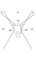
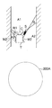
- FIG. 1A is a diagram illustrating an example of a visual field range that can be seen from a front window W1 and a side window W2 provided at the tip end portion T of the endoscope of one embodiment.
- the side window W2 is provided so as to go around the outer circumference of the cylindrical tip portion T.
- the front window W1 is provided in front of the light receiving surface of the image sensor I provided at the tip portion T, and is a window through which the region in the front direction (upward in FIG. 1A) of the light receiving surface can be seen through the objective lens.
- the side window W2 is provided in front of the light receiving surface of the image sensor I, and is a window through which the region in the direction orthogonal to the front (lateral direction shown in FIG. 1A) can be seen through the objective lens.
- the side window W2 in the present embodiment is a window facing sideways orthogonal to the front, but it may be facing sideways as compared with the front window W1.
- the direction of the side window W2 (the direction in which the central axis of the visual field range seen from the side window W2 faces) may be inclined, for example, 30 degrees to 90 degrees with respect to the front.
- the visual field range that can be seen through the objective lens (not shown) provided in the front window W1 and the tip portion T includes the area A1 and the region B, and the visual field range that can be seen through the objective lens (not shown) provided in the side window W2 and the tip portion T. Has a region A2 and a region B.
- the area B overlaps the field of view seen from the front window W1 and the field of view seen from the side window W2, the area B is hereinafter referred to as the overlapping area B.
- the visual field range seen from the front window W1 and the side window W2 does not include the illustrated region C. That is, since the subject in the region C is not included in any of the visual field ranges, it is not reflected in the image captured by the image sensor I.
- the area C is referred to as a blind spot area C.
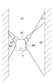
- FIG. 1B is a diagram for explaining an example of the lateral position of the tip T of the endoscope in the organ and the difference in the visual field range in the left-right direction at that time.
- the visual field range of the surface of the living tissue in the organ differs depending on the lateral position of the tip T in the organ.
- the entire visual field range seen from the right front window W1 and the side window W2 in FIG. 1B includes the area A1, the overlapping area B, and the area A2.
- the entire visual field range seen from the left front window W1 and the side window W2 in FIG. 1B includes the area A1 and the area A2 because the tip T is biased to the left in the organ, and is a blind spot. Does not include region C. Therefore, there is a blind spot region C in the visual field range of the image sensor I.
- the lesion portion is the anterior window W1. It is in the visual field range that can be seen from the side window W2 and is in the visual field range that can be seen from the side window W2. Therefore, the image sensor I can image the image of the feature portion seen from the front window W1 and the image of the feature portion seen from the side window W2 as one image through the objective lens.
- FIG. 2A is a diagram for explaining the line-of-sight direction of the feature portion S from the front window W1 and the side window W2 to the feature portion S.
- FIG. 2B is a diagram showing an example of a captured image of the feature portion S shown in FIG. 2A.
- 2A and 2B show the central axis Ax1 extending in the normal direction of the window surface passing through the window center of the front window W1 and the window center of the window width of the side window W2 in the normal direction of the window surface.
- the central axis Ax2 extending to is shown. Since the central axis Ax1 is on an extension line of the optical axis of the objective lens described later, it appears as a point in the captured image.
- the side window W2 is provided so as to go around the circumference of the cylindrical tip portion T, it appears as a circumferential shape in the captured image.
- the feature portion S is in the overlapping region B, two images of the feature portion S appear in the captured image as shown in FIG. 2B.
- the three-dimensional expansion processing unit immediately uses the lines of sight V1 and V2 from the two images of the feature portion S to the feature portion S to perform the principle of triangulation.
- the position information in the depth direction (forward) is obtained by. In the example shown in FIG.
- the depth direction seen from the front window W1 and the side window W2 is not an upward direction but an inclined direction inclined from the upper direction to the lateral direction, and the line of sight V1 to the feature portion S Using V2, for example, the distance and direction from the window center of the front window W1 to the feature portion S can be obtained. Therefore, using the distance and direction of the feature portion S, it is possible to obtain the position information in the height direction from the surface of the feature portion S in the organ with reference to the boundary portion between the feature portion S and the non-feature portion. Further, it is also possible to obtain the position information in the front direction (upward in FIG. 2A) from the window center of the front window W1 to the feature portion S.
- the three-dimensional expansion processing unit immediately obtains the above-mentioned three-dimensional information when the feature portion S enters the overlapping region B and two images of the feature portion S appear, and the biological tissue of the feature portion S.
- the three-dimensional position information including the position information in the height direction protruding from the surface of the feature portion S and the position information in the front direction of the feature portion S is immediately obtained.
- the tip of the endoscope images the surface of a living tissue in an organ while moving downward, so that the feature portion S shown in FIG. 2A is located in the overlapping region B.
- the feature portion S is located in the region A2 of the visual field range of the side window W2, and only one of the feature portions S appears in the captured image.
- two images of the feature portion S appear in the captured image.
- the captured image shows an example of a circular shape in consideration of the fact that the field of view is circular, but on the monitor, a rectangular display screen in which a part of the circular shape is cut out is shown. It may be displayed as.
- the image of the feature portion S becomes one in the captured image. Therefore, when the feature portion S is located in the overlap region B and two images of the feature portion S appear in the captured image, the overlap region B is eliminated and the surface in the organ is treated as if the region A1, the overlap region B, and the region A2. Can be created as an image viewed through one window, for example, the front window W1. Moreover, when two images of the feature portion S appear, the three-dimensional information can be obtained immediately. Therefore, when the image of the feature portion S is displayed on the monitor, the three-dimensional information is reflected in the image, that is, the three-dimensional image. Can be. For example, since the information in the height direction of the feature portion S can be obtained, it is possible to perform a rendering process for reproducing the surface unevenness of the feature portion S with respect to the surrounding portion.
- the process of expanding to the above-mentioned three-dimensional information is performed using the information in the line-of-sight direction to the feature portion S seen from the front window W1 and the side window W2, but is not necessarily limited to the front window W1 and the side window W2.
- a plurality of windows provided at different positions may be used.
- a plurality of windows may be provided on the tip surface of the tip portion T.
- the images of the feature portion S are common to two or more captured images taken at different imaging positions when the tip portion T is moved in the organ, for example.
- a process of expanding to three-dimensional information may be performed using the captured image appearing in the above.
- the three-dimensional information in order to perform the process of expanding to three-dimensional information, it is preferable to acquire at least the distance information between the imaging positions, which is the information of the imaging position.
- the three-dimensional information can be obtained by using the direction of the line of sight of the same feature portion S and the acquired distance information.
- the captured image viewed from three or more windows or the captured image at three or more imaging positions may be used. In this case, since the amount of information becomes excessive, it is preferable to perform the calculation so that the calculation error is minimized when the three-dimensional information is obtained by the principle of triangulation.
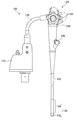
- FIG. 3 is an external perspective view of the endoscope of one embodiment.
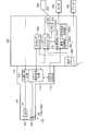
- FIG. 4 is a block diagram showing the configuration of the endoscope system of one embodiment.
- FIG. 4 is a diagram showing an example of the configuration of the tip portion of the endoscope of one embodiment.
- the endoscope (hereinafter referred to as an electronic scope) 100 shown in FIG. 3 is connected to the processor 200 for the electronic endoscope shown in FIG. 4 to form the endoscope system 1.
- the endoscope system 1 is a system specialized for medical use, and as shown in FIG. 4, mainly includes an electronic scope 100, a processor 200 for an electronic endoscope, and a monitor 300.
- the electron scope 100 and the monitor 300 are connected to the processor 200, respectively.
- the electron scope 100 mainly includes a connector 110, an operation unit 120, and a tip portion 132, and can extend from the operation unit 120 toward the front tip portion 132 and have flexibility.
- the flexible cable 130 includes a curved tube 134 that is connected to the front of the flexible cable 130 via a connecting portion and bends freely, and a universal tube 128 that extends rearward from the operating portion 120.
- the connector 110 is fixed to the rear end of the universal tube 128 and is configured to be connected to the processor 200.
- a plurality of bending operation wires are inserted into the operation unit 120, the flexible cable 130, and the bending tube 134, and the tip of each bending operation wire is connected to the rear end of the bending tube 134 to be rear of each bending operation wire.
- the end is connected to the curved operation knob 122 of the operation unit 120.
- the curved pipe 134 is curved in an arbitrary direction by an arbitrary angle according to the operation of the bending operation knob 122.
- the operation unit 120 includes a plurality of operation buttons 124.
- the operation button 124 is such that when the endoscope operator (operator or assistant) presses the operation button 124, water or gas is discharged from an air supply / water supply port (not shown) provided on the tip surface of the tip portion 132. It is possible to instruct each function such as suction of a liquid or gas in a living tissue by a suction port and discharge of a cleaning liquid from a cleaning liquid discharge nozzle for cleaning an objective lens.
- the operation to be performed can be determined in advance, and the operation button 124 can be assigned a function to execute the operation.
- the tip 132 at the tip of the curved tube 134 is made of a hard resin material (eg, ABS, modified PPO, PSU, etc.) that does not substantially elastically deform.
- a hard resin material eg, ABS, modified PPO, PSU, etc.
- an LED light source 102 and an image sensor 108 located immediately after the objective lens 106 are provided inside the tip 132. That is, the tip portion 132 provided at the tip of the long flexible cable 130 includes the LED light source 102, the objective lens 106, and the image pickup element 108.
- the objective lens 106 is provided on the front surface of the image pickup element 108, and an image of living tissue is formed on the light receiving surface of the image pickup element 108 in a viewing angle of 180 degrees or more, preferably more than 180 degrees.
- the tip portion 132 is provided with a front window facing forward of the light receiving surface of the image sensor 108 and a side window facing side orthogonal to the front, and the front window and the side window.
- the image sensor 108 is configured to take an image of an image formed on the light receiving surface by the objective lens 106.
- the flexible cable 130, the curved tube 134, and the tip portion 132 form an insertion portion 135 to be inserted into the body cavity.
- the image signal cable extending from the image sensor 108 provided at the tip 132 passes through the inside of the curved tube 134, the flexible cable 130, the operation section 120, and the universal tube 128 from the tip 132 of the connector 110. It extends to the inside.
- the connector 110 is connected to the processor 200.
- the processor 200 processes the image signal sent from the image sensor and controls the monitor 300 to display the image of the subject captured by the image sensor 108.
- the processor 200 of the endoscope system 1 includes a system controller 202 and a timing controller 206.
- the system controller 202 executes various programs stored in the memory 204 and controls the entire electronic endoscopy system 1 in an integrated manner. Further, the system controller 202 changes various settings of the electronic endoscope system 1 according to an instruction by the endoscope operator (operator or assistant) input to the operation panel 208.
- the timing controller 206 outputs a clock pulse for adjusting the operation timing of each part to each circuit in the electronic endoscope system 1.
- the tip 132 of the electron scope 100 is provided with an LED light source 102 in addition to the image sensor 108.
- the LED light source 102 emits illumination light that illuminates the living tissue for imaging by the image sensor 108.
- the LED light source 102 is driven by a drive signal generated by the light source control circuit 116 provided in the connector 110 to emit light.
- a laser element may be used, or a high-brightness lamp such as a xenon lamp, a metal halide lamp, a mercury lamp or a halogen lamp may be used.
- the LED light source 102 is provided at the tip portion 132, but may be provided at the connector 110 or the processor 200 as a light source device. In this case, from the light source device to the tip 132, the illumination light is guided to the tip 132 through a light guide in which a plurality of fiber cables are bundled.
- the light emitted from the LED light source 102 is irradiated to the living tissue as the subject through the light distribution lens 104 as illumination light.
- the reflected light from the living tissue forms an optical image on the light receiving surface of the image sensor 108 through the front window 140, the side window 150 (see FIG. 3), and the objective lens 106.
- the image sensor 108 is, for example, a single-plate color CCD (Charge-Coupled Device) image sensor in which various filters of an IR (Infrared) cut filter 108a and a Bayer-arranged color filter 108b are arranged on a light receiving surface, and is on the light receiving surface. Each primary color signal of R (Red), G (Green), and B (Blue) corresponding to the imaged optical image is generated.
- a single-plate color CCD image sensor a single-plate color CMOS (Complementary Metal Oxide Semiconductor) image sensor can also be used. In this way, the electron scope 100 uses the image sensor 108 to image the biological tissue inside the organ and generate a moving image.
- CCD Charge-Coupled Device
- a driver signal processing circuit 112 is provided inside the connector 110 of the electronic scope 100.
- the driver signal processing circuit 112 performs predetermined signal processing such as color interpolation and matrix calculation on the primary color signal input from the image pickup element 108 to generate an image signal (brightness signal Y, color difference signal Cb, Cr).
- the generated image signal is output to the image processing unit 220 of the electronic endoscope processor 200.
- the driver signal processing circuit 112 accesses the memory 114 and reads out the unique information of the electronic scope 100.
- the unique information of the electronic scope 100 recorded in the memory 114 includes, for example, the number of pixels and sensitivity of the image sensor 108, the frame rate that can be operated, the model number, and the like.
- the driver signal processing circuit 112 outputs the unique information read from the memory 114 to the system controller 202.
- the system controller 202 performs various operations based on the information stored in the memory 204 and the unique information of the electronic scope 100, and generates a control signal.
- the system controller 202 uses the generated control signal to operate each circuit in the electronic endoscope processor 200 so that processing suitable for the electronic scope 100 connected to the electronic endoscope processor 200 is performed. And control the timing.
- the timing controller 206 supplies clock pulses to the driver signal processing circuit 112, the image processing unit 220, and the light source unit 230 according to the timing control by the system controller 202.
- the driver signal processing circuit 112 drives and controls the image pickup element 108 at a timing synchronized with the frame rate of the image processed on the electronic endoscope processor 200 side according to the clock pulse supplied from the timing controller 206.
- the image processing unit 220 Under the control of the system controller 202, the image processing unit 220 generates a video signal for displaying an image or the like on a monitor based on the image signal input from the driver signal processing circuit 112, and outputs the image processing unit 220A to the monitor 300. (See FIG. 4).
- the image processing unit 220 further includes a three-dimensional expansion processing unit 220B (see FIG. 4) configured to expand the two-dimensional information of the image of the feature portion in the image captured by the image pickup element 108 to the three-dimensional information.
- the three-dimensional expansion processing unit 220B will be described later.
- the image processing unit 220A performs a quantification process on the image of the living tissue obtained by the electron scope 100 to quantify the feature amount of each pixel of the image that can distinguish the lesion part from the healthy part.
- the degree of progression of the lesion may be evaluated, and a color map image may be generated in which the numerical value of each pixel obtained by the digitization process is replaced with a color.
- the image processing unit 220A generates information on the result of the digitization processing and a video signal for displaying the color map image on the monitor, and outputs the video signal to the monitor 300.
- the endoscope operator can accurately perform the inspection through the image displayed on the display screen of the monitor 300.
- the image processing unit 220A outputs an image, information on the result of digitization processing, and a color map image to the printer 400 as needed.
- the processor 200 is connected to the server 600 via the NIC (Network Interface Card) 210 and the network 500.
- the processor 200 can download information related to the endoscopic examination (for example, patient electronic medical record information and operator information) from the server 600.
- the downloaded information is displayed, for example, on the display screen of the monitor 300 or the operation panel 208.
- the processor 200 can save the inspection result in the server 600 by uploading the inspection result by the electronic scope 100 to the server 600.
- FIG. 5 is a diagram illustrating an example of the internal structure of the tip portion 132.
- the tip 132 includes an objective lens 106, an image sensor 108, a front window 140, and a side window 150.
- the objective lens 106 and the image sensor 108 are arranged on the tubular member 133 formed of the hard resin material at the tip portion 132.
- the tip 132 corresponds to the tip T in the examples shown in FIGS. 1A, 1B and 2A.
- the front window 140 faces the front direction of the light receiving surface 108c of the image sensor 108.
- the side window 150 faces sideways orthogonal to the front.
- the side window 150 faces the side orthogonal to the front, but as described above, the side window 150 may face the side side with respect to the front window 140.
- the objective lens 106 is composed of a lens group of lenses 106a to 106e including a meniscus lens, a convex lens, and a concave lens, and has a half angle of view of more than 90 degrees, preferably 110 degrees or more. Therefore, the objective lens 106 simultaneously forms an image of the direct view image of the living tissue obtained through the front window 140 and the side view image of the living tissue obtained through the side window 150 on the light receiving surface 108c as an image.
- the surface of the lens 106a on the subject side also serves as the front window 140.
- a cover glass is provided on the side window 150.
- the viewing range seen from the front window 140 and the side window 150 of the tip portion 132 includes the area A1, the overlapping area B, and the area A2. Further, there is a blind spot region C in which the subject cannot be seen from the front window 140 and the side window 150. Since the image of the living tissue simultaneously captures the direct view image obtained through the front window 140 and the side view image obtained through the side window 150, the captured image has two characteristic portions S as shown in FIG. 2B. May appear as.
- the image processing unit 220 is a three-dimensional expansion processing unit that obtains three-dimensional information of the feature portion S from the two-dimensional information (x-coordinate position and y-coordinate position on the captured image) of the images of the two feature portions S appearing in the captured image. It is equipped with 220B.
- the three-dimensional expansion processing unit 220B has two features commonly included in each of the two images (direct view image and side view image) obtained through the front window 140 and the side window 150 in the captured image captured by the electronic scope 100. Based on the position information in each of the images of the portion S, the direction of the line of sight to the feature portion S seen through the front window 140 and the side window 150 is calculated, and the calculated direction of the line of sight is used to calculate the direction of the line of sight of the image of the feature portion S. Extend 2D information to 3D information. Whether or not the two images obtained through the front window 140 and the side window 150 are common is the position in the captured image of the two feature portions S and the color information of the feature portion S or the outer shape information of the feature portion S. Can be determined by.
- the feature portion S moves from the region A2 to the overlapping region B, so that the captured image has two common features. Whether or not the portion S appears can be easily determined by using a plurality of captured images generated in time series. It should be noted that the two-dimensional information of the image of the feature portion S is three-dimensional information not only when the tip 132 of the electronic scope 100 is moved in one direction and the image is taken while the curved tube 134 is curved. Can be extended to.
- the three-dimensional expansion processing unit 220B is two-dimensional information of each position of interest of the feature portion S in the direct view image obtained through the front window 140 (XY coordinate system having the X and Y directions shown in FIG. 2B as coordinate axes). From the coordinate positions in the X and Y directions (in), the azimuth direction of each position of interest of the feature portion S with respect to the central axis Ax1 of the front window 140 is obtained. Since the central axis Ax1 is set to coincide with the optical axis of the objective lens 106, the directional direction of the feature portion S in the captured image coincides with the directional direction seen from the front window 140 of the tip portion 132 in the organ. do. In the example shown in FIG.
- the lateral direction on the right side with respect to the central axis Ax1 is the directional direction of the above-mentioned attention position of the feature portion S.
- the three-dimensional expansion processing unit 220B obtains the directional direction from the center point Ax2 * of the central axis Ax2 of the side window 150 at each position of interest in the feature portion S in the captured image seen from the side window 150. ..
- the central axes Ax1 and Ax2 are axes extending from the window center of the front window 140 and the side window 150 in the normal direction of the window surface.
- the position of interest when determining the directional direction with respect to the central axis Ax1 and the position of interest when determining the directional direction from the center point Ax2 * are determined by using the color information of the pixel value in the feature portion S or the information of the outer shape. The same position is identified. Further, since the side view image and the direct view image are images obtained by using the same objective lens 106, the directional direction of the position of the feature portion S in the side view image viewed from the central axis Ax1 and the direct view from the central axis Ax1. Since the center point Ax2 * coincides with the directional direction of the same position of the same feature portion S in the image, the center point Ax2 * is from the center axis Ax1 (point shown in FIG. 2B) on the extension line of the optical axis of the objective lens 106 to the feature portion S. The straight line connecting the positions of interest is the intersection with the central axis Ax2 (the circle of the one-point chain line shown in FIG. 2B).
- the central axis Ax2 is an axis extending in the normal direction from the window center of the side window 150, the position coordinates of the position of interest based on the center point Ax2 * in the lateral view are obtained, and the position coordinates of the position of interest are obtained from these position coordinates.
- the angle ⁇ indicating the elevation angle direction (upward direction (forward direction) with respect to the lateral direction in FIG. 2A) shown in FIG. 2A is calculated based on the lens characteristics of the objective lens 106.
- the directions of the lines of sight V1 and V2 with respect to the feature portion S shown in FIGS. 2A and 2B can be obtained.
- the three-dimensional expansion processing unit 220B has a line of sight V1 to this position and the obtained feature portion S. , From the direction of V2, the position where the line of sight V1 to the feature portion S and the line of sight V2 to the feature portion S intersect is calculated by the principle of triangulation.
- the three-dimensional expansion processing unit 220B calculates the directional direction and elevation angle direction of each position of interest of the feature portion S from the window center of the front window 140 or the window center of the side window 150, and distance information. Can be done.
- the three-dimensional expansion processing unit 220B can calculate, for example, the position information of the feature portion S with respect to the tip portion 132 along the extending direction of the organ from the information of the azimuth direction, the elevation angle direction, and the distance, and further, the front window. It is possible to calculate the distance information along the lateral direction (horizontal direction shown in FIG. 2A) from the window center of the 140 or the side window 150 to the position of interest of the feature portion S. As a result, the three-dimensional information of the feature portion S is obtained.
- the image processing unit 220 obtains the three-dimensional information of the feature portion S as described above, but in the captured image, the overlapping region B is eliminated and the surface inside the organ is made as if it were a region.
- A1 the overlapping area B, and the area A2 can be displayed on the monitor 300 by performing a process of creating an image viewed through the front window W1.
- the image of the feature portion S can be displayed on the monitor 300 as a three-dimensional image by performing the three-dimensional processing using the acquired three-dimensional information of the feature portion S.
- Information in the height direction of the feature portion S can be obtained by using the distance information along the lateral direction from the window center of the front window 140 to the position of interest of the feature portion S.
- a rendering process that reproduces the surface irregularities of the portion S can be performed. Since the feature portion S can be displayed on the monitor 300 as a three-dimensional image in this way, it is useful for determining and diagnosing whether or not the tumor needs to be resected.
- the tip 132 is lesioned using the above-mentioned endoscopic system. It is also possible to obtain information on the surface unevenness of the lesion portion by arranging the portions so as to enter the overlapping region B and obtaining three-dimensional information on the lesion portion by the above method.
- the two-dimensional information of the image of the feature portion S is extended to the three-dimensional information by using the image of the biological tissue seen from the front window 140 and the side window 150, but the window provided at the tip portion 132 is provided.
- the front window 140 and the side window 150 are not limited, and a plurality of front windows provided at different positions of the tip portion 132 may be used, or a plurality of side windows provided at different positions of the tip portion 132 may be used. May be used. In this case, since the two windows are provided at different positions on the tip portion 132, the imaging positions are different from each other.
- the three-dimensional expansion processing unit 220B determines the line of sight to the feature portion S that can be seen at different imaging positions based on the position information of the feature portion S that is commonly included in the captured images captured at at least two imaging positions.
- the direction can be used to extend the two-dimensional information of the image of the feature portion S to three-dimensional information.
- the imaging position may be a different position where the electron scope 100 is moved with respect to the living tissue, for example, a different position in the extending direction of the organ.
- the three-dimensional expansion processing unit 220B calculates the three-dimensional information by using the different visible directions of the feature portion S caused by the different imaging positions and the distance information between the imaging positions.
- the distance information between the imaging positions can be obtained from the imaging position information of the tip 132 from the position measuring system of the electronic scope 100.
- the position measurement system uses a magnetic sensor to determine, for example, the position of the image sensor 108 located at the tip 132 of the electronic scope 100 inserted into the organ, and each position of the subsequent flexible cable 130. It is a system to acquire, or a system to acquire the insertion length of the electronic scope 100 inserted from the open end of the organ.
- the objective lens 106 simultaneously connects the direct view image of the living tissue obtained through the front window 140 and the side view image of the living tissue obtained through the side window 150 to the light receiving surface as an image.
- the three-dimensional expansion processing unit 220B is configured to form an image, and the position information in the direct-view image of the feature portion S, which is commonly included in each of the direct-view image and the side-view image in the captured image, and the position information of the feature portion S. Based on the position information in the side view image, the direction of the line of sight to the feature portion S seen through the front window 140 and the side window 150 is calculated, and the calculated direction of the line of sight is used to extend the two-dimensional information to the three-dimensional information. It is preferably configured to do so. Since the front window 140 and the side window 150 have a direction orthogonal to each other as the direction of the central axis of the visual field range, three-dimensional information can be calculated more accurately.
- the images imaged through different windows include overlapping regions B including the same part of the living tissue, and the position information in each image of the feature portion S is characteristic. This is information when the portion S is located in the overlapping area B. Therefore, it is possible to accurately calculate the three-dimensional information from the position information of each position of the image of the feature portion S in one captured image.
- the image pickup positions are two or more different positions, the direction of the line of sight to the feature portion S is different. Therefore, when the image pickup element 108 continuously images the living tissue, the same feature portion S is included.
- the plurality of images may be captured images having different imaging positions before and after the tip 132 of the electronic scope 100 is moved in the body cavity.
- different imaging positions mean that the imaging positions are different from each other in the extending direction of the organ.
- the image processing unit 220 preferably includes the same determination unit 220C in addition to the image processing unit 220A and the three-dimensional expansion processing unit 220B.
- FIG. 6 is a diagram illustrating an example of a configuration of an image processing unit of the endoscope system used in one embodiment.
- the same determination unit 220C determines whether or not the feature portions S included in each of the plurality of images (for example, a direct view image and a side view image) are the same or not, at least in the color information of the feature portion S and the information of the outer shape of the feature portion S. It is configured to be judged using one.
- the image of the feature portion S moves in one direction in the captured image when the moving image is captured, it can be easily determined whether or not they are the same, but when a plurality of feature portions S are present, they are the same. It may be difficult to identify whether or not. Therefore, when calculating the three-dimensional information of the feature portion S, it is preferable to determine whether or not the same determination unit 220C is the same.
- the three-dimensional expansion processing unit 220B has two-dimensional information and three-dimensional information of the image of the feature portion S in a plurality of captured images including the feature portion S of the living tissue, which has been imaged by the electronic scope 100 so far. It is preferable to provide a prediction model in which the relationship between the two-dimensional information and the three-dimensional information is machine-learned using the information as teacher data.
- the prediction model is preferably configured to acquire three-dimensional information by inputting the two-dimensional information of the image of the feature portion S in the image captured by the electron scope 100 into the prediction model. Based on the color information included in the two-dimensional information and the size of the feature portion S, it is possible to predict the three-dimensional information including the information on the surface unevenness of the feature portion S.
- prediction model for example, deep learning by a neural network is used. It is also possible to use a random forest using a tree structure as part of the prediction model.
- a known model such as a convolutional neural network or a stagged autoencoder can be used.
- the image processing unit 220 does not include the three-dimensional expansion processing unit 220B, but includes the prediction unit 220D.
- FIG. 7 is a diagram illustrating an example of a configuration of an image processing unit of the endoscope system used in one embodiment.
- the prediction unit 220D creates a prediction model configured to predict three-dimensional information from the two-dimensional information by inputting the two-dimensional information of the image of the feature portion S included in the captured image captured by the electronic scope 100.
- the prediction model uses the known two-dimensional information of the image of the feature portion S in a plurality of known captured images including the feature portion S and the known three-dimensional information of the corresponding feature portion S as training data, and features in the captured image. This is a machine-learned model of the relationship between the two-dimensional information of the image of the part S and the three-dimensional information of the feature part S.
- machine learning of the prediction model for example, deep learning by a neural network is used.
- a random forest using a tree structure can be used as part of the prediction model.
- a known model such as a convolutional neural network or a stagged autoencoder can be used.
- the image processing unit 220 includes an image display control unit 220E.
- the image sensor 108 continuously images the living tissue as a moving image and displays the image on the monitor 300 using the three-dimensional information obtained from the captured image by the prediction unit 220D, the subject in the blind spot region C is not displayed.
- the three-dimensional image is, for example, a rendered image.
- the image display control unit 220E includes the feature portion S included in the captured image before at least a part of the feature portion S is located in the overlapping region B. It is preferable to display one image of the entire feature portion S using the three-dimensional information predicted from the two-dimensional information of the image, and to control so as to display the three-dimensional image.
- FIGS. 8A to 8C are diagrams for explaining the position of the tip portion T with respect to the feature portion S and an example of the captured image in chronological order.
- the upper part of FIGS. 8A to 8C shows the position of the tip portion T with respect to the feature portion S
- the lower part of FIGS. 8A to 8C shows an example of the display screen 300A of the monitor.
- the examples shown in FIGS. 8A to 8C are described with reference to the examples shown in FIG. 1B.
- the feature portion S Since the portion S is initially located in the region A2 of the viewing range of the side window W2, the feature portion S appears on the display screen 300A of the monitor. After that, when the electron scope 100 is moved, the feature portion S enters the blind spot region C as shown in FIG. 8B. Therefore, the feature portion S disappears from the display screen 300A. Further, when the electron scope 100 is moved, the feature portion S enters the region A1 as shown in FIG. 8C. Therefore, the feature portion S reappears on the display screen 300A.
- the image display control unit 220E is a prediction unit from the two-dimensional information of the image of the feature portion S located in the region A2 before being located in the blind spot region C. Using the three-dimensional information predicted by 220D, the monitor 300 is controlled to display the image of the entire feature portion S as a three-dimensional image. Therefore, the image display control unit 220E extracts the edge region of the feature portion S by the color information, and monitors that the extracted edge region moves with the passage of time.
- the image display control unit 220E displays an image of the entire feature portion S as a three-dimensional image on the monitor 300 using the three-dimensional information predicted by the prediction unit 220D. To control. Further, the image display control unit 220E monitors the movement of the feature portion S whose edge region is extracted by the color information, and when at least a part of the feature portion S enters the overlapping region B, the image of the feature portion S becomes one. It is also possible to create an image so as to be, and control the image of the feature portion S to be displayed as a three-dimensional image created by using the three-dimensional information predicted by the prediction unit 220D.
- FIG. 9A is a diagram showing an example of the position of the tip portion T with respect to the feature portion S
- FIG. 9B is a diagram showing an example of an image displayed on the monitor of the endoscope system of one embodiment.
- the feature portion S1 is located in the region A1
- the feature portion S2 is located in the overlapping region B
- the feature portion S3 is a blind spot. It is located in the area C
- the feature portion S4 is located in the area A2.
- the feature portion S2 located in the overlapping region B does not display two images on the screen, one image is displayed, and the feature portion S3 located in the blind spot region C is displayed as an image without disappearing.
- the images of the feature portions S1 to S4 are all three-dimensional images. It is preferable that the form of the image display as shown in FIG. 9B, in which the feature portions S1 to S4 are three-dimensional images, is selected by pressing the operation button 124 of the operation unit 120 (see FIG. 3). Therefore, the image display on the monitor 300 uses two-dimensional information in which the display as shown in FIG. 9B and the two images of the feature portion S2 in the overlapping region B appear and the feature portion S3 in the blind spot region C is not displayed. It is preferable to switch from the conventional display of the captured image at any time by pressing the operation button 124.
- the three-dimensional expansion processing unit 220B, the prediction unit 220D, the same determination unit 220C, and the image display control unit 220E are provided in the image processing unit 220 of the processor 200, but are not necessarily provided in the processor 200. It does not have to be.
- an image or information may be transmitted / received by being provided in a data processing device provided at another location via the network 500 and communicating via the network 500.
Landscapes
- Health & Medical Sciences (AREA)
- Life Sciences & Earth Sciences (AREA)
- Engineering & Computer Science (AREA)
- Surgery (AREA)
- Physics & Mathematics (AREA)
- Medical Informatics (AREA)
- Radiology & Medical Imaging (AREA)
- Animal Behavior & Ethology (AREA)
- Biophysics (AREA)
- Nuclear Medicine, Radiotherapy & Molecular Imaging (AREA)
- Optics & Photonics (AREA)
- Pathology (AREA)
- Veterinary Medicine (AREA)
- Public Health (AREA)
- Biomedical Technology (AREA)
- Heart & Thoracic Surgery (AREA)
- General Health & Medical Sciences (AREA)
- Molecular Biology (AREA)
- Signal Processing (AREA)
- Multimedia (AREA)
- General Physics & Mathematics (AREA)
- Theoretical Computer Science (AREA)
- Artificial Intelligence (AREA)
- Evolutionary Computation (AREA)
- Computer Vision & Pattern Recognition (AREA)
- Endoscopes (AREA)
- Instruments For Viewing The Inside Of Hollow Bodies (AREA)
Priority Applications (4)
| Application Number | Priority Date | Filing Date | Title |
|---|---|---|---|
| JP2022518057A JP7234461B2 (ja) | 2020-04-28 | 2021-04-26 | 内視鏡システム |
| US17/919,395 US12419503B2 (en) | 2020-04-28 | 2021-04-26 | Endoscope system having a three-dimensional expansion processor |
| CN202180019989.9A CN115279250B (zh) | 2020-04-28 | 2021-04-26 | 内窥镜系统 |
| EP21797476.5A EP4144284A4 (en) | 2020-04-28 | 2021-04-26 | ENDOSCOPE SYSTEM |
Applications Claiming Priority (2)
| Application Number | Priority Date | Filing Date | Title |
|---|---|---|---|
| JP2020079593 | 2020-04-28 | ||
| JP2020-079593 | 2020-04-28 |
Publications (1)
| Publication Number | Publication Date |
|---|---|
| WO2021221017A1 true WO2021221017A1 (ja) | 2021-11-04 |
Family
ID=78373239
Family Applications (1)
| Application Number | Title | Priority Date | Filing Date |
|---|---|---|---|
| PCT/JP2021/016660 Ceased WO2021221017A1 (ja) | 2020-04-28 | 2021-04-26 | 内視鏡システム |
Country Status (5)
| Country | Link |
|---|---|
| US (1) | US12419503B2 (https=) |
| EP (1) | EP4144284A4 (https=) |
| JP (1) | JP7234461B2 (https=) |
| CN (1) | CN115279250B (https=) |
| WO (1) | WO2021221017A1 (https=) |
Families Citing this family (2)
| Publication number | Priority date | Publication date | Assignee | Title |
|---|---|---|---|---|
| CN117651516A (zh) | 2021-08-18 | 2024-03-05 | 豪雅株式会社 | 内窥镜及内窥镜系统 |
| US12205314B2 (en) * | 2022-09-06 | 2025-01-21 | Olympus Medical Systems Corp. | Image processing apparatus for a plurality of timeseries images acquired by an endoscope, image processing method, and recording medium |
Citations (6)
| Publication number | Priority date | Publication date | Assignee | Title |
|---|---|---|---|---|
| US20140152802A1 (en) * | 2012-06-08 | 2014-06-05 | SeeScan, Inc. | Multi-camera pipe inspection apparatus, systems and methods |
| WO2017145270A1 (ja) * | 2016-02-23 | 2017-08-31 | オリンパス株式会社 | 画像処理装置、画像処理方法および内視鏡 |
| JP2018057799A (ja) | 2016-09-29 | 2018-04-12 | 富士フイルム株式会社 | 内視鏡システム及び内視鏡システムの駆動方法 |
| WO2019244345A1 (ja) * | 2018-06-22 | 2019-12-26 | オリンパス株式会社 | ランドマーク推定方法、及び、内視鏡装置 |
| JP2020512089A (ja) * | 2017-03-24 | 2020-04-23 | シーメンス ヘルスケア ゲゼルシヤフト ミツト ベシユレンクテル ハフツング | 奥行き知覚を高める仮想陰影 |
| JP2020079593A (ja) | 2018-05-24 | 2020-05-28 | Tpr株式会社 | 鋳包み用シリンダライナ、及びシリンダブロックの製造方法 |
Family Cites Families (16)
| Publication number | Priority date | Publication date | Assignee | Title |
|---|---|---|---|---|
| US7443488B2 (en) * | 2005-05-24 | 2008-10-28 | Olympus Corporation | Endoscope apparatus, method of operating the endoscope apparatus, and program to be executed to implement the method |
| US20070161854A1 (en) * | 2005-10-26 | 2007-07-12 | Moshe Alamaro | System and method for endoscopic measurement and mapping of internal organs, tumors and other objects |
| JP2012170774A (ja) * | 2011-02-24 | 2012-09-10 | Fujifilm Corp | 内視鏡システム |
| US20150062299A1 (en) * | 2013-08-30 | 2015-03-05 | The Regents Of The University Of California | Quantitative 3d-endoscopy using stereo cmos-camera pairs |
| WO2015122355A1 (ja) | 2014-02-14 | 2015-08-20 | オリンパス株式会社 | 内視鏡システム |
| CN105722450B (zh) * | 2014-02-14 | 2018-01-23 | 奥林巴斯株式会社 | 内窥镜系统 |
| EP3130273B1 (en) * | 2015-08-13 | 2019-05-15 | MedicalTek Co., Ltd. | Stereoscopic visualization system and method for endoscope using shape-from-shading algorithm |
| CN108135453B (zh) * | 2015-09-28 | 2021-03-23 | 奥林巴斯株式会社 | 内窥镜系统和图像处理方法 |
| WO2018037778A1 (ja) * | 2016-08-26 | 2018-03-01 | オリンパス株式会社 | 計測処理装置 |
| JP6779089B2 (ja) * | 2016-10-05 | 2020-11-04 | 富士フイルム株式会社 | 内視鏡システム及び内視鏡システムの駆動方法 |
| US10521052B2 (en) * | 2017-07-31 | 2019-12-31 | Synaptics Incorporated | 3D interactive system |
| US20190186287A1 (en) * | 2017-12-20 | 2019-06-20 | Plasma Igniter, LLC | Power-generation Turbine Including Resonator-based Diagnostics |
| US11026585B2 (en) * | 2018-06-05 | 2021-06-08 | Synaptive Medical Inc. | System and method for intraoperative video processing |
| JP2020024286A (ja) * | 2018-08-07 | 2020-02-13 | オリンパス株式会社 | 計測装置、計測装置の作動方法、およびプログラム |
| US11457981B2 (en) * | 2018-10-04 | 2022-10-04 | Acclarent, Inc. | Computerized tomography (CT) image correction using position and direction (P andD) tracking assisted optical visualization |
| US20200294234A1 (en) * | 2019-03-13 | 2020-09-17 | Matchlab, Inc. | Methods and systems for automatedly collecting and ranking dermatological images |
-
2021
- 2021-04-26 EP EP21797476.5A patent/EP4144284A4/en active Pending
- 2021-04-26 WO PCT/JP2021/016660 patent/WO2021221017A1/ja not_active Ceased
- 2021-04-26 CN CN202180019989.9A patent/CN115279250B/zh active Active
- 2021-04-26 US US17/919,395 patent/US12419503B2/en active Active
- 2021-04-26 JP JP2022518057A patent/JP7234461B2/ja active Active
Patent Citations (6)
| Publication number | Priority date | Publication date | Assignee | Title |
|---|---|---|---|---|
| US20140152802A1 (en) * | 2012-06-08 | 2014-06-05 | SeeScan, Inc. | Multi-camera pipe inspection apparatus, systems and methods |
| WO2017145270A1 (ja) * | 2016-02-23 | 2017-08-31 | オリンパス株式会社 | 画像処理装置、画像処理方法および内視鏡 |
| JP2018057799A (ja) | 2016-09-29 | 2018-04-12 | 富士フイルム株式会社 | 内視鏡システム及び内視鏡システムの駆動方法 |
| JP2020512089A (ja) * | 2017-03-24 | 2020-04-23 | シーメンス ヘルスケア ゲゼルシヤフト ミツト ベシユレンクテル ハフツング | 奥行き知覚を高める仮想陰影 |
| JP2020079593A (ja) | 2018-05-24 | 2020-05-28 | Tpr株式会社 | 鋳包み用シリンダライナ、及びシリンダブロックの製造方法 |
| WO2019244345A1 (ja) * | 2018-06-22 | 2019-12-26 | オリンパス株式会社 | ランドマーク推定方法、及び、内視鏡装置 |
Non-Patent Citations (1)
| Title |
|---|
| See also references of EP4144284A4 |
Also Published As
| Publication number | Publication date |
|---|---|
| EP4144284A4 (en) | 2024-05-15 |
| JP7234461B2 (ja) | 2023-03-07 |
| JPWO2021221017A1 (https=) | 2021-11-04 |
| CN115279250A (zh) | 2022-11-01 |
| US20230157526A1 (en) | 2023-05-25 |
| EP4144284A1 (en) | 2023-03-08 |
| US12419503B2 (en) | 2025-09-23 |
| CN115279250B (zh) | 2025-04-29 |
Similar Documents
| Publication | Publication Date | Title |
|---|---|---|
| US12349985B2 (en) | Device and method for tracking the position of an endoscope within a patient's body | |
| JP7124011B2 (ja) | システム、及び出血検出システムの作動方法 | |
| US11793402B2 (en) | System and method for generating a three-dimensional model of a surgical site | |
| JP7385731B2 (ja) | 内視鏡システム、画像処理装置の作動方法及び内視鏡 | |
| US20020188172A1 (en) | Endoscopic system | |
| JP6454489B2 (ja) | 観察システム | |
| JP3707830B2 (ja) | 術式支援用画像表示装置 | |
| JPH0695009B2 (ja) | 撮像手段による対象部分の検査方法 | |
| JP6987243B2 (ja) | ランドマーク推定方法、内視鏡装置、及び、位置推定プログラム | |
| JP7234461B2 (ja) | 内視鏡システム | |
| US20230062782A1 (en) | Ultrasound and stereo imaging system for deep tissue visualization | |
| JP6906342B2 (ja) | 内視鏡システム | |
| JPH01209415A (ja) | 計測機能付き内視鏡装置 | |
| JPH02297515A (ja) | 立体視電子内視鏡 | |
| CN114126474B (zh) | 内窥镜形状显示控制装置、内窥镜形状显示控制装置的操作方法、及计算机可读介质 | |
| JP2021171475A (ja) | 内視鏡及び内視鏡システム | |
| JP2021016631A (ja) | 内視鏡形状表示制御装置、内視鏡形状表示制御装置の作動方法、および内視鏡形状表示制御装置の作動プログラム |
Legal Events
| Date | Code | Title | Description |
|---|---|---|---|
| 121 | Ep: the epo has been informed by wipo that ep was designated in this application |
Ref document number: 21797476 Country of ref document: EP Kind code of ref document: A1 |
|
| ENP | Entry into the national phase |
Ref document number: 2022518057 Country of ref document: JP Kind code of ref document: A |
|
| NENP | Non-entry into the national phase |
Ref country code: DE |
|
| ENP | Entry into the national phase |
Ref document number: 2021797476 Country of ref document: EP Effective date: 20221128 |
|
| WWG | Wipo information: grant in national office |
Ref document number: 202180019989.9 Country of ref document: CN |
|
| WWG | Wipo information: grant in national office |
Ref document number: 17919395 Country of ref document: US |