WO2021220686A1 - 走行台車、及び、自動倉庫 - Google Patents
走行台車、及び、自動倉庫 Download PDFInfo
- Publication number
- WO2021220686A1 WO2021220686A1 PCT/JP2021/012701 JP2021012701W WO2021220686A1 WO 2021220686 A1 WO2021220686 A1 WO 2021220686A1 JP 2021012701 W JP2021012701 W JP 2021012701W WO 2021220686 A1 WO2021220686 A1 WO 2021220686A1
- Authority
- WO
- WIPO (PCT)
- Prior art keywords
- traveling
- guide member
- traveling carriage
- guide
- rail
- Prior art date
- Legal status (The legal status is an assumption and is not a legal conclusion. Google has not performed a legal analysis and makes no representation as to the accuracy of the status listed.)
- Ceased
Links
Images


Classifications
-
- B—PERFORMING OPERATIONS; TRANSPORTING
- B65—CONVEYING; PACKING; STORING; HANDLING THIN OR FILAMENTARY MATERIAL
- B65G—TRANSPORT OR STORAGE DEVICES, e.g. CONVEYORS FOR LOADING OR TIPPING, SHOP CONVEYOR SYSTEMS OR PNEUMATIC TUBE CONVEYORS
- B65G1/00—Storing articles, individually or in orderly arrangement, in warehouses or magazines
- B65G1/02—Storage devices
- B65G1/04—Storage devices mechanical
- B65G1/06—Storage devices mechanical with means for presenting articles for removal at predetermined position or level
- B65G1/065—Storage devices mechanical with means for presenting articles for removal at predetermined position or level with self propelled cars
-
- B—PERFORMING OPERATIONS; TRANSPORTING
- B65—CONVEYING; PACKING; STORING; HANDLING THIN OR FILAMENTARY MATERIAL
- B65G—TRANSPORT OR STORAGE DEVICES, e.g. CONVEYORS FOR LOADING OR TIPPING, SHOP CONVEYOR SYSTEMS OR PNEUMATIC TUBE CONVEYORS
- B65G1/00—Storing articles, individually or in orderly arrangement, in warehouses or magazines
- B65G1/02—Storage devices
- B65G1/04—Storage devices mechanical
- B65G1/0407—Storage devices mechanical using stacker cranes
- B65G1/0435—Storage devices mechanical using stacker cranes with pulling or pushing means on either stacking crane or stacking area
-
- B—PERFORMING OPERATIONS; TRANSPORTING
- B65—CONVEYING; PACKING; STORING; HANDLING THIN OR FILAMENTARY MATERIAL
- B65G—TRANSPORT OR STORAGE DEVICES, e.g. CONVEYORS FOR LOADING OR TIPPING, SHOP CONVEYOR SYSTEMS OR PNEUMATIC TUBE CONVEYORS
- B65G2203/00—Indexing code relating to control or detection of the articles or the load carriers during conveying
- B65G2203/02—Control or detection
- B65G2203/0266—Control or detection relating to the load carrier(s)
- B65G2203/0283—Position of the load carrier
-
- B—PERFORMING OPERATIONS; TRANSPORTING
- B65—CONVEYING; PACKING; STORING; HANDLING THIN OR FILAMENTARY MATERIAL
- B65G—TRANSPORT OR STORAGE DEVICES, e.g. CONVEYORS FOR LOADING OR TIPPING, SHOP CONVEYOR SYSTEMS OR PNEUMATIC TUBE CONVEYORS
- B65G2203/00—Indexing code relating to control or detection of the articles or the load carriers during conveying
- B65G2203/04—Detection means
- B65G2203/042—Sensors
- B65G2203/044—Optical
Definitions
- the present invention includes a traveling carriage that travels along a predetermined direction, particularly a traveling carriage that travels guided by a traveling rail extending along the predetermined direction, and a rack that stores the traveling carriage and luggage. Regarding automated warehouses to prepare.
- a traveling carriage that is provided for each of the shelves provided in a plurality of stages in the height direction and travels along the length direction of the shelves provided.
- the traveling carriage travels along the length direction of the shelf by being guided by a traveling rail extending along the length direction of the shelf provided with the traveling carriage.
- the traveling bogie is provided with a pair of traveling assist rollers that assist the traveling of the traveling carriage side by side in the length direction of the traveling rail (for example, Patent Document 1).
- one of a pair of traveling assist rollers is attached to a front frame provided on the front side in the traveling direction, and the other traveling assist roller is attached to a rear frame provided on the rear side in the traveling direction.
- the front frame and the rear frame are connected by a pair of members extending in the traveling direction of the traveling carriage.
- a traveling bogie with such a configuration a machining error of a member connecting the front frame and the rear frame, an installation error when connecting the front frame and the rear frame, a machining error of other components of the traveling bogie, and / or ,
- the front frame and the rear frame may not be arranged exactly in parallel due to installation errors of the other components.
- the traveling assist rollers provided on the front frame and the traveling assist rollers provided on the rear frame may not be accurately arranged side by side in parallel in the traveling direction. If the traveling auxiliary rollers are not arranged exactly parallel to the traveling direction, the traveling bogie will not be properly arranged with respect to the traveling rail, and the traveling bogie will not be able to travel appropriately along the traveling rail.
- An object of the present invention is to accurately arrange a plurality of traveling auxiliary rollers along a traveling direction in a traveling carriage provided with a plurality of traveling assisting rollers that travel along a predetermined traveling direction and are arranged side by side in the traveling direction. To do.
- the traveling trolley according to the first aspect of the present invention is a traveling trolley that travels on a traveling route extending in the first direction.
- the traveling carriage includes a side arm, a guide member, and at least two or more traveling assist rollers.
- the side arm expands and contracts in the second direction.
- the second direction is a direction orthogonal to the first direction in the horizontal direction.
- the guide member extends in the first direction and has a guide surface that guides the side arm in the first direction. At least two or more traveling assist rollers are provided on the guide member to suppress the movement of the traveling carriage in the second direction.
- a plurality of traveling auxiliary rollers are provided on the guide member extending in the same first direction as the traveling direction of the traveling carriage. Since the guide member extends in the first direction, that is, in the traveling direction of the traveling carriage, by providing the guide member with a plurality of traveling assist rollers, a plurality of traveling assisting rollers can be provided along the traveling direction of the traveling carriage. Can be placed accurately. As a result, the straightness of the traveling carriage can be improved.
- the guide member may be provided over the entire length of the traveling carriage in the first direction. Further, the guide member may have a first portion for guiding the side arm and a second portion located outside the first portion in the first direction. In this case, the traveling auxiliary roller may be provided on the second portion of the guide member.
- the traveling assistance roller By providing the traveling assistance roller in the second portion of the guide member, the traveling assistance roller can be provided at the end of the entire length of the traveling carriage in the first direction, so that the traveling direction can be extended over the entire length of the traveling carriage in the first direction.
- the traveling auxiliary roller can be arranged in parallel with the vehicle. As a result, the straightness of the traveling carriage can be improved.
- a pair of guide members may be provided so as to be separated from each other in the second direction.
- the traveling carriage may further include a first connecting member and a second connecting member.
- the first connecting member and the second connecting member connect the pair of guide members inside the guide member in the second direction on the end side of the pair of guide members in the first direction.
- the traveling carriage can be assembled with the guide member as a reference while using the guide member as a member for guiding the side arm in the first direction. That is, the guide member can have a function of guiding the side arm and a function as a frame of the traveling carriage. As a result, the number of parts of the traveling carriage can be reduced.
- the traveling carriage may further include an auxiliary member provided on the guide member.
- the auxiliary member is a current collecting member for supplying power to the traveling carriage, a detecting member for detecting the traveling position of the traveling carriage, a stopper for stopping the traveling carriage, or irradiating light outward with respect to the first direction. It may be at least one of the photoelectric devices. In this way, by providing the auxiliary member for assisting the traveling of the traveling carriage with the guide member as a reference, it becomes easy to assemble the auxiliary member to the traveling carriage.
- the photoelectric device may be mounted on the mounting surface of the mounting member that is in contact with the guide member so as to irradiate the light outward with respect to the first direction.
- the traveling carriage may further include a block member.
- the block member is fixed to the guide member in a state of being inserted into the space formed in the guide member. At least one of the traveling auxiliary roller and the auxiliary member is attached to the block member. Thereby, the traveling auxiliary roller and / or the auxiliary member can be collectively attached to the common block member, and the traveling auxiliary roller and / or the auxiliary member can be easily attached to the guide member.
- the traveling path may include a traveling plane portion and a movement restraining portion.
- the traveling plane portion is a portion serving as a traveling plane of the traveling carriage.
- the movement restraining portion is a portion extending in the third direction from the traveling plane portion, and the traveling auxiliary roller abuts on the portion to suppress the movement of the traveling carriage in the second direction.
- the third direction is a direction orthogonal to the first direction and the second direction.
- the traveling auxiliary roller may have a pair of rollers.
- the pair of rollers are arranged in the second direction at predetermined intervals. Further, the movement restraining portion is sandwiched between the pair of rollers. As a result, the movement of the traveling carriage in the second direction can be further suppressed.
- the cross section of the guide member may have either a C-shape, an L-shape, or a square shape. As a result, the rigidity of the guide member can be increased.
- the block member may be able to be pulled out from the end portion of the guide member in the first direction from the state of being inserted into the guide member. Further, the block member may be inserted into the guide member by inserting the block member in the first direction from the end portion of the guide member. As a result, the traveling auxiliary roller and / or the auxiliary member can be easily attached to and detached from the guide member while the traveling carriage is installed on the traveling path.
- the automated warehouse includes the above-mentioned traveling carriage, luggage transferred from the traveling carriage, and / or a rack for storing luggage transferred to the traveling carriage.
- the plurality of traveling auxiliary rollers can be accurately arranged along the traveling direction of the traveling carriage. As a result, the straightness of the traveling carriage in the first direction can be improved.
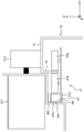
- FIG. 1 Top view of automated warehouse.
- Perspective view of the trolley and rack An enlarged view of the vicinity of the traveling portion of the traveling carriage when viewed from the X direction.
- Detailed perspective view of the traveling trolley A perspective view of the guide member of the traveling carriage and the parts associated therewith from the upper right side.
- FIG. 1 is a top view of the automated warehouse 100
- FIG. 2 is a perspective view of the traveling carriage 7 and the rack 1.
- FIG. 3 is an enlarged view of the vicinity of the traveling portion 31 of the traveling carriage 7 when viewed from the X direction.
- the left-right direction of FIG. 1 is referred to as the X direction (an example of the first direction)
- the vertical direction of FIG. 1, that is, the direction orthogonal to the X direction in the horizontal direction is the Y direction (an example of the second direction).
- the automated warehouse 100 includes a rack 1, an elevating / conveying device 3, a warehousing / delivery station 5, a plurality of traveling carriages 7, and rails 7a (an example of traveling routes).
- Rack 1 stores luggage W.
- the rack 1 has a plurality of shelves 11.
- the plurality of shelves 11 extend in the X direction and are arranged side by side at predetermined intervals in the Z direction.
- the luggage W is placed and stored on any of the plurality of shelves 11.
- each shelf 11 is provided with a relay conveyor 13.
- the relay conveyor 13 is provided in the vicinity of the elevating and transporting device 3, and the luggage W to be stored is transferred from the elevating and transporting device 3.
- the luggage W to be delivered is transferred from the traveling carriage 7.
- the rack 1 is arranged on only one side in the Y direction with respect to the traveling carriage 7 (rail 7a).
- the present invention is not limited to this, and racks 1 may be arranged on both sides in the Y direction with respect to the traveling carriage 7 (rail 7a).
- the elevating and lowering transfer device 3 is arranged between the rack 1 and the warehousing / delivery station 5 and has an elevating table.
- the elevating table can be elevated in the Z direction while supporting a plurality of loads in the elevating and conveying device 3.
- the lift has, for example, a conveyor for transferring the luggage W between the warehousing / delivery station 5 and the relay conveyor 13 of the rack 1.
- the warehousing / delivery station 5 transports the luggage W stored (warehousing) on the shelf 11 of the rack 1 from the outside to the vicinity of the lifting / lowering transport device 3. In addition, the warehousing / delivery station 5 transports the package W transported by the elevating / lowering transport device 3 for warehousing toward the outside.
- the warehousing / delivery station 5 is, for example, a transport device such as a belt conveyor.
- the rail 7a is a member provided on each shelf 11 of the rack 1 and extending in the X direction.
- the traveling carriage 7 provided on each shelf 11 travels in the X direction guided by the rail 7a provided on the corresponding shelf 11.
- the rail 7a has a traveling plane portion 71 and a movement suppressing portion 73.
- the traveling plane portion 71 is a portion parallel to the XY plane and extending in the X direction, and is a traveling plane on which the traveling carriage 7 travels.
- the movement restraining portion 73 is a portion extending in the Z direction and extending in the X direction from the end portion of the traveling plane portion 71 in the Y direction. The movement restraining portion 73 prevents the traveling carriage 7 from moving in the Y direction when the roller 27a of the traveling auxiliary roller 27 comes into contact with the roller 27a.
- the rail 7a Since the rail 7a has the above-mentioned traveling plane portion 71 and the movement suppressing portion 73, the rail 7a has a function as a traveling path of the traveling carriage 7 and a function of suppressing the movement of the traveling carriage 7 in the Y direction with respect to the rail 7a. And can be given.
- Each of the plurality of traveling trolleys 7 is a trolley capable of traveling along the X direction at a height corresponding to the height of each shelf 11.
- the traveling carriage 7 travels along the X direction by being laid at a height corresponding to each shelf 11 and being guided by a rail 7a extending in the X direction. Further, the traveling carriage 7 has a transfer device 25 (FIG. 4) for transferring the luggage W between the relay conveyor 13 of the rack 1 and the shelf 11.
- the traveling carriage 7 can convey the held luggage W in the X direction by traveling in the X direction along the shelf 11 on which the traveling carriage 7 is arranged while holding the luggage W. Further, the luggage W can be transferred between the traveling carriage 7 and the relay conveyor 13 and between the traveling carriage 7 and the shelf 11 by using the transfer device provided on the traveling carriage 7. Specifically, at the time of warehousing of the luggage W, after the luggage W transferred from the elevating transport device 3 to the relay conveyor 13 is transferred to the traveling carriage 7, the traveling carriage 7 moves in the X direction to the target position of the shelf 11. The luggage W is transferred from the traveling carriage 7 to the shelf 11 at the target position.
- the traveling carriage 7 moves along the X direction to the target position of the shelf 11, and after transferring the luggage W from the shelf 11 to the traveling carriage 7 at the target position, the traveling carriage 7 relays the conveyor. It moves along the X direction to the arrangement position of 13, and the luggage W is transferred from the traveling carriage 7 to the relay conveyor 13.
- FIG. 4 is a detailed perspective view of the traveling carriage 7.
- FIG. 5 is a perspective view of the guide member of the traveling carriage 7 and the parts and the like attached thereto as viewed from the upper right side.
- FIG. 6 is a perspective view of the guide member of the traveling carriage 7 and the parts and the like attached thereto as viewed from the upper left side.
- FIG. 7 is a perspective view of the guide member of the traveling carriage 7 and the parts and the like attached thereto as viewed from the lower left side.
- FIG. 8 is a diagram showing a definition of a surface of the guide member.
- the traveling carriage 7 includes a first guide member 21a, a second guide member 21b, a first main body portion 23a, a second main body portion 23b, a transfer device 25, and a traveling auxiliary roller 27.
- the first guide member 21a has a function of guiding the movement of the side arm 253 of the transfer device 25 and a function as a frame for determining a reference position of each component in the traveling carriage 7. It is a member having and.
- the first guide member 21a is a member that is long in one direction. As shown in FIGS. 5 to 8, the first guide member 21a has a C-shape in a cross section perpendicular to the length direction.
- the first guide member 21a has a first inner surface IP1, a second inner surface IP2, and a third inner surface IP3 as C-shaped inner surfaces.
- the first inner side surface IP1 is a plane long in the length direction of the first guide member 21a, and is a surface arranged at the lower part of the C-shape.
- the second inner surface IP2 is a surface that is long in the length direction of the first guide member 21a and is parallel to the first inner surface IP1, and is a surface that is arranged on the upper part of the C-shape.
- the third inner surface IP3 is long in the length direction of the first guide member 21a, and is a surface that forms an angle of 90 degrees with the first inner surface IP1 and the second inner surface IP2.
- the third inner surface IP3 connects the first inner surface IP1 and the second inner surface IP2.
- the first guide member 21a has a first outer surface OP1, a second outer surface OP2, and a third outer surface OP3.
- the first outer surface OP1 is a plane long in the length direction of the first guide member 21a, and is a surface arranged at the lower part of the C-shape.
- the second outer surface OP2 is a surface long in the length direction of the first guide member 21a and parallel to the first outer surface OP1, and is a surface arranged on the upper part of the C-shape.
- the third outer surface OP3 is long in the length direction of the first guide member 21a, and is a surface that forms an angle of 90 degrees with the first outer surface OP1 and the second outer surface OP2.
- the third inner surface IP3 connects the first inner surface IP1 and the second inner surface IP2.
- the rigidity of the first guide member 21a can be increased.
- the length direction of the first guide member 21a is parallel to the length direction of the rail 7a (that is, the X direction). That is, the first guide member 21a is a member extending in the X direction parallel to the rail 7a in the traveling carriage 7.
- the fact that the length direction of the first guide member 21a is parallel to the length direction of the rail 7a means that, specifically, as shown in FIG. 3, when the traveling carriage 7 is installed on the rail 7a, the first guide member 21a is first.
- the third inner surface IP3 and the third outer surface OP3 of the guide member 21a are parallel to the movement restraining portion 73 parallel to the XX plane of the rail 7a, and the first inner surface IP1 and the first guide member 21a are parallel to each other. 2 The state in which the inner surface IP2, the first outer surface OP1, and the second outer surface OP2 are parallel to the traveling plane portion 71 parallel to the XY plane of the rail 7a.
- the first guide member 21a since the first guide member 21a has a surface parallel to the rail 7a when the traveling carriage 7 is installed, the first guide member 21a can be used as a frame for determining the reference position of each component of the traveling carriage 7. ..
- the first block member 27b to which various members (traveling auxiliary roller 27, auxiliary member) of the traveling carriage 7 are attached comes into contact with the first inner surface IP1 and the third inner surface IP3. In this state, it is attached to the first guide member 21a.
- the first inner side surface IP1 is parallel to the traveling plane portion 71 of the rail 7a
- the third inner side surface IP3 is parallel to the movement suppressing portion 73 of the rail 7a. That is, in the present embodiment, the two reference surfaces when the first block member 27b is attached to the first guide member 21a are parallel to the traveling plane portion 71 and the movement suppressing portion 73 (that is, the rail 7a) of the rail 7a. It has become.
- the first connecting member 29a and the second connecting member 29b are attached to the first guide member 21a in a state of being in contact with the second outer surface OP2 and the third outer surface OP3.
- the second outer surface OP2 is parallel to the traveling plane portion 71 of the rail 7a
- the third outer surface OP3 is parallel to the movement suppressing portion 73 of the rail 7a.
- the reference surfaces for attaching the first connecting member 29a and the second connecting member 29b to the first guide member 21a are the traveling plane portion 71 and the movement restraining portion 73 (that is, the movement suppressing portion 73) of the rail 7a. It is parallel to the rail 7a).
- the first guide member 21a and the second guide member 21b have a second outer surface OP2 and a third outer surface OP3 parallel to the X direction for attaching the first connecting member 29a and the second connecting member 29b. doing.
- the cross-sectional shape of the first guide member 21a is not limited to the C shape as long as the reference surface on which the various members of the traveling carriage 7 are attached is parallel to the length direction of the rail 7a.
- the cross-sectional shape of the first guide member 21a can be L-shaped or quadrangular.
- the second guide member 21b is a member having the same configuration as the first guide member 21a described above.
- the second guide member 21b is provided apart from the first guide member 21a in the Y direction.
- the second guide member 21b is connected to the first guide member 21a by the first connecting member 29a and the second connecting member 29b.
- the first main body portion 23a constitutes the main body of the front portion of the traveling carriage 7.
- the first main body portion 23a is provided on one end side of the first guide member 21a and the second guide member 21b in the length direction.
- the side on which the first main body portion 23a is provided is defined as the front side of the traveling carriage 7.
- the first main body portion 23a includes a first connecting member 29a and a traveling portion 31.
- the first connecting member 29a connects the first guide member 21a and the second guide member 21b at the front ends of the first guide member 21a and the second guide member 21b. Specifically, as shown in FIGS. 5 and 6, the first connecting member 29a connects the first guide member 21a and the second guide member 21b inside in the Y direction. That is, the first connecting member 29a is attached in contact with the surface of the first guide member 21a and the second guide member 21b that faces the first guide member 21a or the second guide member 21b.
- the first connecting member 29a is fixed to the first guide member 21a in a state of being in contact with the third outer surface OP3 of the first guide member 21a. Further, the first connecting member 29a is fixed to the second guide member 21b in a state of being in contact with the third outer surface OP3 of the second guide member 21b. As a result, the first connecting member 29a (traveling carriage 7) can be assembled based on the guide member.
- first connecting member 29a is in contact with the horizontal plane (plane parallel to the XY plane) of the first guide member 21a and the second guide member 21b. Specifically, the first connecting member 29a is in contact with the second outer surface OP2 of the first guide member 21a. Further, the first connecting member 29a is in contact with the second outer surface OP2 of the second guide member 21b. Thereby, the position of the first connecting member 29a in the height direction can be determined with reference to the guide member.
- the reference that the first connecting member 29a is parallel to the length direction (X direction) of the rail 7a such as the second outer surface OP2 and the third outer surface OP3 of the first guide member 21a and the second guide member 21b.
- the first guide member 21a and the second guide member 21b can be made parallel.
- the first connecting member 29a is connected to the inner surfaces facing each other such as the third outer surface OP3 of the first guide member 21a and the third outer surface OP3 of the second guide member 21b, and the first guide member 21a.
- the first connecting member is attached by abutting on surfaces having the same positional relationship such as the same horizontal plane (plane parallel to the XY plane) such as the outer surface OP2 and the second outer surface OP2 of the second guide member 21b. 29a can be properly positioned.
- the traveling portion 31 is provided at the left and right (Y direction) ends of the first main body portion 23a, and causes the traveling carriage 7 to travel along the rail 7a.
- the traveling unit 31 has a drive motor 311 and wheels 313.
- the drive motor 311 is, for example, a motor fixed to a bracket BR (FIG. 3) provided on the first main body 23a.
- the bracket BR for fixing the drive motor 311 is preferably in contact with the second outer surface OP2 and the third outer surface OP3 of the first guide member 21a and the second guide member 21b. Thereby, the mounting position (position in the Y direction and the Z direction) of the drive motor 311 can be determined with reference to the guide member.
- the wheel 313 is connected to the output rotation shaft of the drive motor 311 at a position where the circumferential portion contacts the traveling plane portion 71 of the rail 7a.
- the traveling carriage 7 can travel along the traveling plane portion 71 of the rail 7a along the rail 7a.
- the second main body portion 23b is the other end of the first guide member 21a and the second guide member 21b in the length direction, that is, the side where the first main body portion 23a is provided. Is provided at the opposite end. That is, the second main body portion 23b is provided on the rear end side of the traveling carriage 7. In other words, the second main body 23b constitutes the main body at the rear of the traveling carriage 7.
- the second main body 23b has a second connecting member 29b and a driven wheel 33.
- the second connecting member 29b connects the first guide member 21a and the second guide member 21b at the rear ends of the first guide member 21a and the second guide member 21b. Specifically, as shown in FIGS. 5 and 6, the second connecting member 29b connects the first guide member 21a and the second guide member 21b inside in the Y direction. That is, the second connecting member 29b is attached in contact with the surface of the first guide member 21a and the second guide member 21b that faces the first guide member 21a or the second guide member 21b.
- the second connecting member 29b is fixed to the first guide member 21a in a state of being in contact with the third outer surface OP3 of the first guide member 21a. Further, the second connecting member 29b is fixed to the second guide member 21b in a state of being in contact with the third outer surface OP3 of the second guide member 21b. As a result, the second connecting member 29b (traveling carriage 7) can be assembled with the guide member as a reference.
- the second connecting member 29b is in contact with the horizontal plane (plane parallel to the XY plane) of the first guide member 21a and the second guide member 21b. Specifically, the second connecting member 29b is in contact with the second outer surface OP2 of the first guide member 21a. Further, the second connecting member 29b is in contact with the second outer surface OP2 of the second guide member 21b. Thereby, the position of the second connecting member 29b in the height direction can be determined with reference to these guide members.
- the second connecting member 29b is attached to the reference surfaces such as the second outer surface OP2 and the third outer surface OP3 of the first guide member 21a and the second guide member 21b.
- the guide member 21b can be parallel to each other.
- the second connecting member 29b is connected to the inner surfaces facing each other such as the third outer surface OP3 of the first guide member 21a and the third outer surface OP3 of the second guide member 21b, and the first guide member 21a.
- the second connecting member is attached by abutting on surfaces having the same positional relationship such as the same horizontal plane (plane parallel to the XY plane) such as the outer surface OP2 and the second outer surface OP2 of the second guide member 21b. 29b can be properly positioned.
- the first connecting member 29a and the second connecting member 29b have the same length, and both ends of the first guide member 21a and the second guide member 21b in the length direction. Is in contact with the second outer surface OP2 and the third outer surface OP3. As a result, the first guide member 21a and the second guide member 21b can be made parallel to each other in the X direction, the Y direction, and the Z direction.
- the traveling carriage 7 By providing the first connecting member 29a and the second connecting member 29b on the end side of the first guide member 21a and the second guide member 21b extending over the entire length of the traveling carriage 7 in the traveling direction, the traveling carriage The required number of members for accurately mounting each component of 7 can be reduced. As a result, the number of parts of the traveling carriage 7 can be reduced. This is because the first guide member 21a and the second guide member 21b can have a plurality of functions. Specifically, since most of the components of the traveling carriage 7 are provided on the first main body portion 23a or the second main body portion 23b, the first guide member 21a and the second guide member 21b to which the main body portion is fixed are provided with respect to the first main body portion 23a or the second main body portion 23b.
- first guide member 21a and the second guide member 21b can serve as guides for moving the side arm 253 (frame 251) in the X direction.
- the driven wheels 33 are provided on the left and right sides of the second connecting member 29b so as to be rotatable around the central axis at a height position where the circumferential portion contacts the traveling plane portion 71 of the rail 7a, and the rails follow the traveling of the traveling carriage 7. It rotates on the traveling plane portion 71 of 7a.
- the transfer device 25 is a device for transferring the luggage W between the traveling carriage 7 and the shelf 11 of the rack 1.
- the transfer device 25 is provided between the first main body portion 23a and the second main body portion 23b at the upper part of the first guide member 21a and the second guide member 21b in the traveling carriage 7.
- the transfer device 25 mainly includes a pair of frames 251 and a pair of side arms 253.
- one of the pair of frames 251 is omitted in order to ensure the clarity of the figure.
- the frame 251 slidably supports the side arm 253 in the Y direction by an arm rail (not shown) provided on the side surface.
- an arm rail (not shown) provided on the side surface.
- sliding members 251a that are slidable with respect to the third inner side surface IP3 (an example of the guide surface) of the first guide member 21a and the second guide member 21b, respectively. Is provided.
- the frame 251 can move in the X direction between the first main body portion 23a and the second main body portion 23b.
- the first guide member 21a has a third inner side surface IP3 parallel to the X direction that guides the frame 251 of the transfer device 25 by sliding the sliding member 251a as described above. There is.
- the sliding member 251a is the rail 7a. Can move exactly in parallel in the length direction of. That is, the frame 251 that can be moved in the X direction by the sliding member 251a can move exactly parallel to the length direction of the rail 7a. Further, since the first guide member 21a and the second guide member 21b are parallel to each other by the first connecting member 29a and the second connecting member 29b, the frame 251 is parallel to the length direction of the rail 7a. You can move smoothly.
- first portion the portion in which the frame 251 is movable is referred to as a "first portion".
- first portion the distance in the X direction between the first main body portion 23a and the frame 251 of the portions in the length direction of the first guide member 21a and the second guide member 21b is a load. It is a portion from a position that is substantially the same as the minimum width of W to a mounting position of the second main body portion 23b.
- second portion a portion outside the first portion in the length direction and provided with the first main body portion 23a and the second main body portion 23b is referred to as a "second portion”.
- the "second portion” is a portion of the first guide member 21a and the second guide member 21b in the length direction from the end portion of the guide member on the first main body portion 23a side to the first main body portion.
- the first guide member 21a and the second guide member 21b that guide the frame 251 include not only the first portion in which the frame 251 can move, but also the second portion extending in the length direction from the first portion.
- the second portion is formed by being extended from the first portion by utilizing the linearity of the first portion parallel to the length direction of the rail 7a, so that the second portion is formed in the length direction of the rail 7a. It is parallel.
- various members of the traveling carriage 7 are attached to the second part of the guide member. As a result, the various members can be attached in parallel with the length direction of the rail 7a. Further, since various members of the traveling carriage 7 can be attached to the guide member, it is possible to have a function as a member for guiding the frame 251 with respect to the guide member and a function as a frame for attaching various members.
- a ball screw 251b (FIG. 4) having a thread formed over almost the entire length direction is screwed into the frame 251.
- the frame 251 By rotating the ball screw 251b according to the rotation of a motor (not shown), for example, the frame 251 can be moved in parallel (X direction) with the length direction of the rail 7a.
- both of the pair of frames 251 may have the above-mentioned sliding member 251a and can move in the X direction, or only one of the pair of frames 251 has the above-mentioned sliding member 251a and X. It may be movable in the direction.
- the side arm 253 expands and contracts in the Y direction with respect to the frame 251 by the arm rail provided on the frame 251.
- the side arm 253 is provided with a member (not shown) that meshes with the spline of the spline member 253b extending in the X direction.
- the side arm 253 is rotated by a motor (not shown) to rotate the spline member 253b. Can be moved (expanded and contracted) in the Y direction.
- a hook 253a is rotatably provided around an axis extending in the Y direction at the end of the side arm 253 in the Y direction.
- the hook 253a rotates with respect to the side arm 253 so that its length direction is directed to the X direction, and hooks the luggage W later.
- the hook 253a is in a state where its length direction is directed to the Z direction, as shown in FIG.
- the traveling assist roller 27 suppresses the movement of the traveling carriage 7 in the Y direction when traveling along the X direction.
- the traveling auxiliary roller 27 has a pair of rollers 27a arranged at predetermined intervals in the Y direction.
- the pair of rollers 27a are rotatably attached to the shaft extending in the Z direction in the first block member 27b.
- the pair of rollers 27a sandwich the movement suppressing portion 73 of the rail 7a between them.
- one traveling assist roller 27 is fixed to the second portion on the front side of the first guide member 21a, and one is fixed to the second portion on the rear side of the first guide member 21a. A total of two will be provided.
- the traveling auxiliary roller 27 is provided on the first block member 27b. Specifically, a pair of rollers 27a are provided on the first block member 27b. Further, as shown in FIG. 3, the contact surface AP of the first block member 27b abuts and is fixed to the third inner side surface IP3 of the first guide member 21a, so that the front and rear traveling auxiliary rollers 27 are X. It will be fixed to the common third inner surface IP3 of the first guide member 21a extending in the direction.
- the front and rear traveling assistance rollers 27 are extended in the X direction and fixed to the common third inner side surface IP3 parallel to the X direction (the length direction of the rail 7a), whereby the front and rear traveling assistance rollers 27 are attached.
- the traveling trolley 7 can be accurately arranged on the traveling trolley 7 without being significantly deviated from the traveling direction (X direction) of the traveling trolley 7. Further, by attaching the traveling assist roller 27 to the first guide member 21a having the third inner side surface IP3 parallel to the rail 7a, the first guide member 21a and the rail 7a can be maintained parallel to each other.
- front and rear traveling auxiliary rollers 27 are arranged without being significantly deviated from the traveling direction of the traveling carriage 7, that is, the extending direction of the rail 7a, so that the traveling carriage 7 is parallel to the rail 7a during traveling. There will be no significant deviation in the Y direction. That is, the straightness of the traveling carriage 7 with respect to the rail 7a is improved.
- the first main body portion 23a is provided in the second portion on the front side of the first guide member 21a and the second guide member 21b, and the second main body portion 23b is provided after the first guide member 21a and the second guide member 21b.
- the provision on the second portion on the side means that the first guide member 21a and the second guide member 21b extend over the entire length of the traveling carriage 7 in the traveling direction (X direction). Therefore, one of the traveling assist rollers 27 is fixed to the second portion on the front side of the first guide member 21a, and the other one of the traveling assist rollers 27 is fixed to the second portion on the rear side of the first guide member 21a. Means that two traveling auxiliary rollers 27 are provided on both ends of the traveling carriage 7 in the traveling direction.
- the two traveling auxiliary rollers 27 are provided on the common third inner side surface IP3 of the first guide member 21a parallel to the rail 7a and on both ends of the traveling carriage 7 in the traveling direction.
- the two traveling auxiliary rollers 27 can be exactly parallel to the rail 7a over the entire length of the bogie 7.
- traveling assistance roller 27 is fixed to the first guide member 21a by the first block member 27b, the traveling assistance roller 27 can be easily attached and detached.
- the traveling carriage 7 when the traveling carriage 7 is installed on the rail 7a, the pair of rollers 27a of the traveling auxiliary rollers 27 are in a state of sandwiching the movement suppressing portion 73 of the rail 7a. Therefore, if the traveling auxiliary roller 27 is attached to the traveling carriage 7 in advance before the traveling carriage 7 is installed on the rail 7a, the traveling carriage 7 and the rail 7a need to be aligned when the traveling carriage 7 is installed on the rail 7a. It becomes difficult to sandwich the movement suppressing portion 73 between the pair of rollers 27a, and the load of the installation work increases.
- the traveling carriage 7 to which the traveling assistance roller 27 is not attached is installed on the rail 7a
- the first block member 27b to which the traveling assistance roller 27 is attached is attached to the first guide member 21a from the end of the first guide member 21a.
- the traveling auxiliary roller 27 when the traveling auxiliary roller 27 is removed from the traveling carriage 7, the traveling auxiliary roller 27 is released from the fixing of the first block member 27b to which the traveling auxiliary roller 27 is attached while the traveling carriage 7 is installed on the rail 7a, and the first guide is released.
- the traveling auxiliary roller 27 can be easily removed from the traveling carriage 7 by pulling out the first block member 27b inserted into the C-shape of the member 21a from the end of the first guide member 21a. That is, the traveling auxiliary roller 27 can be easily removed from the traveling carriage 7 without removing the traveling carriage 7 from the rail 7a.
- the first block member 27b is in contact with not only the third inner side surface IP3 but also the first inner side surface IP1 when the first guide member 21a is fixed. Thereby, the position of the traveling auxiliary roller 27 in the height direction can be determined with reference to the first guide member 21a.
- the traveling carriage 7 includes an auxiliary member.
- the auxiliary member is various members or devices used for traveling the traveling carriage 7, transferring the luggage W between the shelf 11 and the traveling carriage 7 by the transfer device 25, and the like.
- the traveling carriage 7 includes a current collecting member 41, a detecting member 43, a stopper 45, and a photoelectric device 47 as auxiliary members. In the traveling carriage 7, unnecessary members among the above auxiliary members can be omitted.
- the current collecting member 41 has an electrode that is provided on the rail 7a and abuts on a trolley member (not shown) that supplies electric power, and is a member that collects electric power supplied from the trolley member to the traveling carriage 7.
- the current collecting member 41 is fixed to the first block member 27b fixed to the second portion on the front side of the first guide member 21a. In this way, the current collecting member 41 is provided in the second portion of the first guide member 21a via the first block member 27b. This makes it easier to assemble the current collector member 41 to the traveling carriage 7. For example, by pulling out the first block member 27b from the first guide member 21a or inserting the first block member 27b into the first guide member 21a as described above, the current collecting member 41 can be easily traveled. It can be attached to and detached from the dolly 7.
- the detection member 43 detects the traveling position of the traveling carriage 7 on the rail 7a.
- the detection member 43 is, for example, a device that detects the light that has passed through the slit provided in the rail 7a and detects the position of the slit 7a in which the slit is provided.
- the detection member 43 may be a device for identifying identification information such as a barcode reader or a QR code (registered trademark) reader.
- the detection member 43 is provided in the second portion of the first guide member 21a via the first block member 27b, similarly to the current collector member 41.
- the stopper 45 abuts on, for example, a stop member (not shown) provided on the rail 7a to stop the traveling carriage 7 at a place on the rail 7a where the stop member is provided.
- the stopper 45 is provided at the front end (second portion) of the second guide member 21b via a second block member 35 fixed to the third inner side surface IP3 of the second guide member 21b. Therefore, it is provided on the second guide member 21b.
- the photoelectric device 47 is a device that irradiates light from the traveling carriage 7 to the side opposite to the front direction, that is, from the traveling carriage 7 to the outside (rear side) in the X direction.
- the photoelectric device 47 is, for example, a communication device that communicates between the traveling carriage 7 and another device, and / or a distance sensor that measures the distance between the traveling carriage 7 and another member in the X direction. Is.
- the photoelectric device 47 is attached to the first guide member 21a via the attachment member 47a.
- the mounting member 47a is fixed in contact with the first block member 27b in the second portion of the first guide member 21a. Since the first block member 27b in contact with the third inner side surface IP3 of the first guide member 21a is parallel to the X direction in which the rail 7a extends, the mounting member is in contact with and fixed to the first block member 27b. 47a is also parallel to the X direction.
- the mounting member 47a to the first guide member 21a that enables the transfer device 25 (frame 251) to move in parallel in the X direction, and further mounting the photoelectric device 47 on the mounting surface of the mounting member 47a.
- the first guide member 21a is parallel to the X direction (the length direction of the rail 7a)
- the irradiation direction of light from the photoelectric device 47 and the X direction are parallel to each other. It is possible to reduce the deviation between the light irradiation direction from the photoelectric device 47 and the X direction (the traveling direction of the traveling carriage 7).
- the auxiliary member (current collector 41, detection member 43, stopper 45, photoelectric device 47) and the traveling auxiliary roller 27 are connected to the first guide member 21a parallel to the X direction via the first block member 27b. It is fixed to the third inner surface IP3 of. That is, the first guide member 21a and the second guide member 21b have a third inner side surface IP3 parallel to the X direction for attaching the traveling auxiliary roller 27 and the auxiliary member.
- the auxiliary members (current collector 41, detection member 43, photoelectric device 47) and the traveling auxiliary roller 27 are attached to the first block member 27b.
- the auxiliary member and the traveling auxiliary roller 27 can be collectively attached to the common member with the first block member 27b, and the auxiliary member and the traveling auxiliary roller 27 can be easily attached to the first guide member 21a.
- the first block member 27b can be inserted into the C-shape from the end of the first guide member 21a, and the first block member 27b inserted inside the C-shape is the first. 1 It can be pulled out from the end of the guide member 21a.
- the auxiliary member and the traveling assistance are provided with the traveling carriage 7 installed on the rail 7a.
- the roller 27 can be easily attached to the traveling carriage 7 with a small amount of work. Further, by pulling out the first block member 27b from the end of the first guide member 21a with the traveling carriage 7 installed on the rail 7a, the auxiliary member and the traveling auxiliary roller with the traveling carriage 7 installed on the rail 7a. 27 can be easily removed from the traveling carriage 7 with a small amount of work.
- the housing of the photoelectric device 47 is brought into direct contact with either the first inner side surface IP1 to the third inner side surface IP3 or the first outer surface OP1 to the third outer surface OP3 of the first guide member 21a. May be fixed. In this case, the housing of the photoelectric device 47 becomes the mounting member 47a.
- traveling auxiliary roller 27 and / or the above-mentioned auxiliary member is attached to either the first inner side surface IP1 to the third inner side surface IP3 or the first outer surface OP1 to the third outer surface OP3 of the first guide member 21a. It may be fixed by directly contacting it.
- the traveling assistance roller 27 and the photoelectric device 47 may be individually attached to the guide member.
- the traveling auxiliary roller 27 and the photoelectric device 47 are provided at separate positions, for example, the photoelectric device 47 is attached to the end of the traveling carriage 7 so as to face outward (for example, communication provided at the end of the rail 7a).
- the traveling auxiliary roller 27 may be provided inside the traveling carriage 7.
- the traveling auxiliary roller 27 may be provided with reference to any surface of the first guide member 21a as a reference for the position of the traveling carriage 7.
- the traveling assist roller 27 is provided in a state of being in contact with the second outer surface OP2 at the lower part of the first guide member 21a and the third outer surface OP3 on the side surface. May be good.
- FIG. 9 is a diagram showing a modified example of the installed state of the traveling auxiliary roller 27 on the guide member of the traveling carriage 7.
- the traveling carriage 7 (an example of a traveling carriage) is a traveling carriage traveling on a rail 7a (an example of a traveling route) extending in the X direction (an example of the first direction), and is a traveling unit 31 (an example of a traveling unit).
- a side arm 253 (an example of a side arm), a first guide member 21a (an example of a guide member), and at least two or more traveling assist rollers 27 (an example of a traveling assist roller) are provided.
- the traveling unit 31 travels the traveling carriage 7 in the X direction.
- the side arm 253 expands and contracts in the Y direction (an example of the second direction).
- the first guide member 21a extends in the X direction and has a third inner surface IP3 (an example of a guide surface) that guides the side arm 253 in the X direction. At least two or more traveling assist rollers 27 are provided on the first guide member 21a to suppress the movement of the traveling carriage 7 in the Y direction.
- a plurality of traveling auxiliary rollers 27 are provided on the first guide member 21a extending in the same X direction as the traveling direction of the traveling carriage 7. Since the first guide member 21a extends in the traveling direction of the traveling carriage 7, by providing the first guide member 21a with a plurality of traveling assisting rollers 27, the plurality of traveling assisting rollers 27 can be moved in the traveling direction of the traveling carriage 7. Can be placed accurately along. As a result, the straightness of the traveling carriage 7 can be improved.
- the transfer device 25 is not limited to the rear hook type transfer device.
- it may be a side clamp type transfer device.
- the number of guide members provided on the traveling carriage 7 is not limited to 2 (pair). For example, only the first guide member 21a may be provided as the guide member, and the second guide member 21b may be omitted.
- the traveling auxiliary roller 27, the auxiliary member, and the photoelectric device 47 are attached to the first block member 27b in contact with the third inner side surface IP3 of the first guide member 21a. That is, the traveling auxiliary roller 27, the auxiliary member, and the photoelectric device 47 were attached to the common third inner side surface IP3 via the first block member 27b.
- a part of the above members may be attached to a surface other than the third inner side surface IP3 of the first guide member 21a as long as the surface is parallel to the length direction (X direction) of the rail 7a.
- the traveling auxiliary roller 27, the auxiliary member, and the photoelectric device 47 are attached to the common third inner surface IP3 via the first block member 27b, and are attached to the first connecting member 29a and the first connecting member 29a.
- the two connecting members 29b were attached in contact with the second outer surface OP2 and the third outer surface OP3 of the first guide member 21a and the second guide member 21b.
- a part or all of the above members may be any surface (even one surface) of the first guide member 21a. It may be attached in contact with a plurality of surfaces).
- the present invention can be widely applied to a traveling carriage traveling along a predetermined direction, particularly a traveling carriage guided by a traveling rail extending along the predetermined direction.
Landscapes
- Engineering & Computer Science (AREA)
- Mechanical Engineering (AREA)
- Warehouses Or Storage Devices (AREA)
- Platform Screen Doors And Railroad Systems (AREA)
Priority Applications (3)
| Application Number | Priority Date | Filing Date | Title |
|---|---|---|---|
| US17/921,421 US12091245B2 (en) | 2020-04-30 | 2021-03-25 | Traveling platform, and automatic warehouse |
| CN202180027193.8A CN115427324A (zh) | 2020-04-30 | 2021-03-25 | 行驶台车以及自动仓库 |
| JP2022517558A JP7332038B2 (ja) | 2020-04-30 | 2021-03-25 | 走行台車、及び、自動倉庫 |
Applications Claiming Priority (2)
| Application Number | Priority Date | Filing Date | Title |
|---|---|---|---|
| JP2020080377 | 2020-04-30 | ||
| JP2020-080377 | 2020-04-30 |
Publications (1)
| Publication Number | Publication Date |
|---|---|
| WO2021220686A1 true WO2021220686A1 (ja) | 2021-11-04 |
Family
ID=78373466
Family Applications (1)
| Application Number | Title | Priority Date | Filing Date |
|---|---|---|---|
| PCT/JP2021/012701 Ceased WO2021220686A1 (ja) | 2020-04-30 | 2021-03-25 | 走行台車、及び、自動倉庫 |
Country Status (5)
| Country | Link |
|---|---|
| US (1) | US12091245B2 (https=) |
| JP (1) | JP7332038B2 (https=) |
| CN (1) | CN115427324A (https=) |
| TW (1) | TWI842992B (https=) |
| WO (1) | WO2021220686A1 (https=) |
Families Citing this family (4)
| Publication number | Priority date | Publication date | Assignee | Title |
|---|---|---|---|---|
| WO2021220686A1 (ja) * | 2020-04-30 | 2021-11-04 | 村田機械株式会社 | 走行台車、及び、自動倉庫 |
| USD1104856S1 (en) * | 2021-10-20 | 2025-12-09 | Intelligrated Headquarters, Llc | Shuttle car |
| USD1101012S1 (en) | 2023-02-21 | 2025-11-04 | Intelligrated Headquarters, Llc | Shuttle car |
| US20250011084A1 (en) * | 2023-07-06 | 2025-01-09 | Intelligrated Headquarters, Llc | Load handling systems and methods of use |
Citations (4)
| Publication number | Priority date | Publication date | Assignee | Title |
|---|---|---|---|---|
| JP2016060623A (ja) * | 2014-09-19 | 2016-04-25 | 株式会社ダイフク | 物品移載装置 |
| JP2016141324A (ja) * | 2015-02-04 | 2016-08-08 | 株式会社岡村製作所 | 搬送台車 |
| JP2016531060A (ja) * | 2013-09-13 | 2016-10-06 | シムボティック エルエルシー | 自動保管および取出システム |
| JP2018115071A (ja) * | 2017-01-20 | 2018-07-26 | 中西金属工業株式会社 | 自走式搬送台車を用いた保管設備 |
Family Cites Families (24)
| Publication number | Priority date | Publication date | Assignee | Title |
|---|---|---|---|---|
| US5551350A (en) * | 1993-10-07 | 1996-09-03 | Daifuku Co., Ltd. | Transporting system driven by linear motor having inductive power supply |
| US5927926A (en) * | 1996-10-21 | 1999-07-27 | Itoki Crebio Corporation | Carriage for storage-retrieval system with locking-engaging members |
| US20060045672A1 (en) * | 1997-07-22 | 2006-03-02 | Maynard Michael D | Rail carriage and rail carriage system |
| JPH11278607A (ja) | 1998-03-25 | 1999-10-12 | Murata Mach Ltd | 自動倉庫 |
| JP2003160047A (ja) * | 2001-11-22 | 2003-06-03 | Asyst Shinko Inc | 搬送装置 |
| JP5332337B2 (ja) * | 2008-06-20 | 2013-11-06 | 株式会社Ihi | 搬送装置及び自動倉庫 |
| JP5432917B2 (ja) * | 2008-10-27 | 2014-03-05 | デマティック アカウンティング サービシーズ ゲーエムベーハー | 立体自動倉庫用の移載シャトル |
| US9522781B2 (en) * | 2010-09-30 | 2016-12-20 | Dematic Systems Gmbh | Shuttle for automated warehouse |
| AT516410B1 (de) * | 2015-04-22 | 2016-05-15 | Tgw Mechanics Gmbh | Verfahren zum Einlagern von Stückgütern in ein Lagerregal und Lagersystem |
| JP6859868B2 (ja) * | 2017-06-22 | 2021-04-14 | 株式会社ダイフク | 物品収納設備 |
| US11117743B2 (en) * | 2017-09-28 | 2021-09-14 | Symbotic Llc | Storage and retrieval system |
| CN207844073U (zh) * | 2018-01-22 | 2018-09-11 | 浙江恒天凡腾科技股份有限公司 | 一种智能立体式染料仓储柜 |
| CN109879169B (zh) * | 2019-01-08 | 2021-04-06 | 上海海事大学 | 起重机轨道检测小车 |
| DE102019104372A1 (de) * | 2019-02-21 | 2020-08-27 | Nedcon B.V. | Warenlager, insbesondere Shuttlelager |
| JP7147735B2 (ja) * | 2019-12-02 | 2022-10-05 | 株式会社ダイフク | 走行レール、及び、物品搬送設備 |
| US12110180B2 (en) * | 2020-01-09 | 2024-10-08 | System Logistics S.P.A. | Movement device |
| IT202000005632A1 (it) * | 2020-03-17 | 2021-09-17 | Automha S P A | Dispositivo di prelievo e/o deposito di articoli per magazzini automatici. |
| WO2021220686A1 (ja) * | 2020-04-30 | 2021-11-04 | 村田機械株式会社 | 走行台車、及び、自動倉庫 |
| EP3960656A1 (en) * | 2020-08-24 | 2022-03-02 | Dematic GmbH | System for storage of goods carriers |
| US12479662B2 (en) * | 2020-09-04 | 2025-11-25 | Murata Machinery, Ltd. | Automated warehouse |
| CN112298890B (zh) * | 2020-11-09 | 2022-08-12 | 北京京东乾石科技有限公司 | 穿梭车 |
| US12391475B2 (en) * | 2021-09-08 | 2025-08-19 | Symbotic Llc | Autonomous transport vehicle |
| US12473146B2 (en) * | 2021-08-12 | 2025-11-18 | Symbotic Llc | Autonomous transport vehicle with vision system |
| US12024363B2 (en) * | 2021-12-13 | 2024-07-02 | Intelligrated Headquarters, Llc | Automated shuttle apparatus and methods of using the same |
-
2021
- 2021-03-25 WO PCT/JP2021/012701 patent/WO2021220686A1/ja not_active Ceased
- 2021-03-25 JP JP2022517558A patent/JP7332038B2/ja active Active
- 2021-03-25 CN CN202180027193.8A patent/CN115427324A/zh active Pending
- 2021-03-25 US US17/921,421 patent/US12091245B2/en active Active
- 2021-04-28 TW TW110115239A patent/TWI842992B/zh active
Patent Citations (4)
| Publication number | Priority date | Publication date | Assignee | Title |
|---|---|---|---|---|
| JP2016531060A (ja) * | 2013-09-13 | 2016-10-06 | シムボティック エルエルシー | 自動保管および取出システム |
| JP2016060623A (ja) * | 2014-09-19 | 2016-04-25 | 株式会社ダイフク | 物品移載装置 |
| JP2016141324A (ja) * | 2015-02-04 | 2016-08-08 | 株式会社岡村製作所 | 搬送台車 |
| JP2018115071A (ja) * | 2017-01-20 | 2018-07-26 | 中西金属工業株式会社 | 自走式搬送台車を用いた保管設備 |
Also Published As
| Publication number | Publication date |
|---|---|
| JP7332038B2 (ja) | 2023-08-23 |
| US12091245B2 (en) | 2024-09-17 |
| CN115427324A (zh) | 2022-12-02 |
| JPWO2021220686A1 (https=) | 2021-11-04 |
| TW202208257A (zh) | 2022-03-01 |
| US20230183001A1 (en) | 2023-06-15 |
| TWI842992B (zh) | 2024-05-21 |
Similar Documents
| Publication | Publication Date | Title |
|---|---|---|
| JP7332038B2 (ja) | 走行台車、及び、自動倉庫 | |
| JP5212836B2 (ja) | ワーク搬送設備 | |
| KR20090027448A (ko) | 차량용 대차 이송 시스템 | |
| CN104837748B (zh) | 搬运设备和自动化仓库 | |
| CN108706260A (zh) | 一种运输车系统、运输车以及仓储物流系统 | |
| KR20150098508A (ko) | 무인 자동 운반장치 | |
| JP2012150588A (ja) | 有軌道台車システム | |
| JP5839285B2 (ja) | 搬送装置 | |
| JP2011032069A (ja) | 搬送装置 | |
| JP2700704B2 (ja) | 自走台車使用の搬送設備 | |
| JPH0558403A (ja) | 自動倉庫設備 | |
| JPH06239448A (ja) | 自走台車使用の搬送設備 | |
| JP4780120B2 (ja) | 有軌道台車システム | |
| JP2001348104A (ja) | 自動倉庫の出し入れ装置 | |
| CN220432256U (zh) | 可接驳搬运车及可接驳搬运系统 | |
| JP7002173B2 (ja) | 移載装置 | |
| CN217024085U (zh) | 一种输送提升复合式的穿梭车 | |
| JP2000355275A (ja) | 有軌道台車システム | |
| CN212981488U (zh) | 一种离散型输送货架 | |
| JP2792262B2 (ja) | 自走台車使用の搬送設備 | |
| JPH03277453A (ja) | 可動体使用の処理設備 | |
| JP2002173224A (ja) | 搬送装置および搬送設備 | |
| JP4003297B2 (ja) | 無人搬送装置 | |
| JP2539010B2 (ja) | 工業用ロボットへのワ―ク供給装置 | |
| JP3431121B2 (ja) | 物品搬送設備 |
Legal Events
| Date | Code | Title | Description |
|---|---|---|---|
| 121 | Ep: the epo has been informed by wipo that ep was designated in this application |
Ref document number: 21796141 Country of ref document: EP Kind code of ref document: A1 |
|
| ENP | Entry into the national phase |
Ref document number: 2022517558 Country of ref document: JP Kind code of ref document: A |
|
| NENP | Non-entry into the national phase |
Ref country code: DE |
|
| 122 | Ep: pct application non-entry in european phase |
Ref document number: 21796141 Country of ref document: EP Kind code of ref document: A1 |