WO2021220606A1 - リアクトル - Google Patents
リアクトル Download PDFInfo
- Publication number
- WO2021220606A1 WO2021220606A1 PCT/JP2021/008107 JP2021008107W WO2021220606A1 WO 2021220606 A1 WO2021220606 A1 WO 2021220606A1 JP 2021008107 W JP2021008107 W JP 2021008107W WO 2021220606 A1 WO2021220606 A1 WO 2021220606A1
- Authority
- WO
- WIPO (PCT)
- Prior art keywords
- reactor
- heat
- magnetic layer
- winding
- reactor according
- Prior art date
- Legal status (The legal status is an assumption and is not a legal conclusion. Google has not performed a legal analysis and makes no representation as to the accuracy of the status listed.)
- Ceased
Links
Images


Classifications
-
- H—ELECTRICITY
- H01—ELECTRIC ELEMENTS
- H01F—MAGNETS; INDUCTANCES; TRANSFORMERS; SELECTION OF MATERIALS FOR THEIR MAGNETIC PROPERTIES
- H01F27/00—Details of transformers or inductances, in general
- H01F27/08—Cooling; Ventilating
- H01F27/22—Cooling by heat conduction through solid or powdered fillings
-
- H—ELECTRICITY
- H01—ELECTRIC ELEMENTS
- H01F—MAGNETS; INDUCTANCES; TRANSFORMERS; SELECTION OF MATERIALS FOR THEIR MAGNETIC PROPERTIES
- H01F37/00—Fixed inductances not covered by group H01F17/00
Definitions
- This disclosure relates to reactors.
- the reactor is provided with an iron core and a coil wound around the iron core via an insulator. Further, the reactor has a heat conductive material sheet interposed between the reactor and the coil (see, for example, Patent Document 1).
- the above reactor dissipates the heat generated by the coil by the heat conductive material sheet to the iron core.
- heat is generated due to the loss of the iron core, so that the temperature of the iron core rises and it is difficult to dissipate heat from the coil.
- the purpose of the present disclosure is to provide a reactor that enables efficient heat dissipation from the coil.
- a reactor according to one aspect of the present disclosure is a reactor that has an upper surface and a lower surface facing opposite sides and is attached with the lower surface facing the mounting surface of a heat radiating member, and is a winding formed by winding a wire rod.
- a coil having a portion and arranged so that the winding portion is parallel to the lower surface, a non-magnetic layer covering the winding portion, and a magnetic core covering the non-magnetic layer. It has a heat transfer member that transfers heat inside the reactor toward the lower surface.
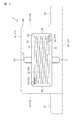
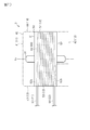
- Sectional drawing of the reactor of 1st Embodiment. Sectional drawing of the reactor of 1st Embodiment.
- Front view showing the reactor of the modified example A side view showing a reactor of a modified example.
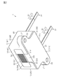
- the reactor 1 of the present embodiment is formed in a rectangular parallelepiped shape, and the upper surface 11 and the lower surface 12 facing the opposite sides and the side surfaces intersecting the upper surface 11 and the lower surface 12 and facing the opposite sides. It has side surfaces 15 and 16 that intersect 13 and 14, the upper surface 11 and the lower surface 12 and the side surfaces 13 and 14 and face opposite to each other.
- the term "rectangular parallelepiped” includes a rectangular parallelepiped in which the corners and ridges are chamfered and a rectangular parallelepiped in which the corners and ridges are rounded. Further, unevenness or the like may be formed on a part or all of the main surface and the side surface.
- the reactor 1 is arranged with the lower surface 12 facing the member to which the reactor 1 is attached, and is fixed to the member.
- the member to which the reactor 1 is attached is, for example, a heat radiating member such as a heat sink.
- the reactor 1 has two lead wires 21 and 22 extending from the side surface 13.
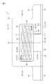
- the reactor 1 has a heat transfer member 30, a magnetic core 40, a non-magnetic layer 50, and a coil 60.
- the heat transfer member 30 has higher thermal conductivity than the magnetic core 40, such as aluminum (Al), copper (Cu), aluminum oxide (Al 2 O 3 ), aluminum nitride (AlN), and the like. Composed of good materials.
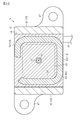
- the heat transfer member 30 has a base plate 31 and heat dissipation columns 34 and 35.
- the base plate 31 has a quadrangular plate-shaped base portion 32 and two fixing portions 33 extending from the base portion 32.
- the base plate 31 has an upper surface 31a and a lower surface 31b, a side surface 31c facing the extending direction of the lead wires 21 and 22, and a side surface 31d facing the side opposite to the side surface 31c. ing.
- the lower surface 31b of the base plate 31 constitutes the lower surface 12 of the reactor 1.
- the heat radiation columns 34 and 35 extend upward from the upper surface 31a of the base plate 31.
- the heat radiating columns 34 and 35 are formed in a rectangular parallelepiped shape.
- the heat radiating column 34 has an inner side surface 34a facing the side of the heat radiating column 35, an outer surface 34b facing the side opposite to the inner side surface 34a, and an upper surface 34c.
- the heat radiating column 35 has an inner side surface 35a facing the side of the heat radiating column 34, an outer surface 35b facing the side opposite to the inner side surface 35a, and an upper surface 35c.
- the heat radiation columns 34 and 35 are integrated with the base plate 31. Then, as shown in FIGS.
- the heat radiating column 34 is formed so that the outer surface 34b is flush with the side surface 31c of the base plate 31.
- the heat radiating column 35 is formed so that the outer surface 35b is flush with the side surface 31d of the base plate 31.
- the upper surfaces 34c and 35c of the heat radiation columns 34 and 35 are in close contact with the non-magnetic layer 50. That is, the tips of the heat radiating columns 34 and 35 extending upward from the base plate 31 are in contact with the non-magnetic layer 50.
- the non-magnetic layer 50 is formed so as to cover the coil 60.
- the coil 60 is a spiral coil formed by winding one wire rod.
- the wire rod of the present embodiment is a flat wire.
- the flat wire is a wire rod having a rectangular cross-sectional shape orthogonal to the length direction of the wire rod.
- the "rectangle" includes a rectangle with chamfered corners and a rectangle with rounded corners.
- the "rectangular shape” includes a shape in which unevenness is formed on a part or all of the sides, and a shape in which a part or all of the sides are curved as a whole.
- a wire rod having a circular cross-sectional shape, an elliptical shape, or a square shape may be used as the wire rod constituting the coil.
- a foil-shaped conductor may be used as the wire rod. Further, conductors may be laminated to form a coil.
- the wire rod 61 constituting the coil 60 includes a core wire 61a and a coating material 61b that covers the surface of the core wire 61a.
- the core wire 61a is made of Cu, Al, an alloy containing Cu or Al as a main component.
- the coating material 61b is an insulating material, for example, an enamel material such as polyimide amide.
- the coil 60 of the present embodiment is formed by using a flat wire as a wire rod and winding the flat wire edgewise.
- the coil 60 may be formed by flatwise winding a flat wire.
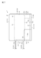
- the coil 60 includes a winding portion 62 having a winding shaft Ax, and a first drawing portion 63 and a second drawing portion 64 extending from the first end 62a and the second end 62b of the winding portion 62, respectively.
- the first drawer portion 63 and the second drawer portion 64 form the lead wires 21 and 22 shown in FIG.
- the winding portion 62 is formed in a quadrangular frame shape when viewed from the direction of the winding shaft Ax.
- the corners of the winding portion 62 are formed in an arc shape (1/4 circle).
- the shape of the winding portion 62 may be a circular shape, an elliptical shape, a polygonal shape, or the like when viewed from the direction of the winding shaft Ax.
- the coil 60 is arranged so that the winding shaft Ax of the winding portion 62 is perpendicular to the lower surface 12 of the reactor 1.
- the non-magnetic layer 50 is formed so as to cover the winding portion 62.
- an insulating resin such as an epoxy resin or a silicone resin can be used.
- the surface of the non-magnetic layer 50 is flat.
- the non-magnetic layer 50 preferably covers, for example, the winding portion 62 with a thickness of 0.1 mm or more and 3 mm or less.
- the non-magnetic layer 50 preferably contains a filler such as silica powder or alumina powder, and preferably has a thermal conductivity of 1 W / m ⁇ K or more.
- the non-magnetic layer 50 can transfer heat satisfactorily.
- the non-magnetic layer 50 is formed by molding such as injection molding, transfer molding, sheet pressing, or the like.
- the non-magnetic layer 50 is formed in a rectangular tubular shape.
- the non-magnetic layer 50 has an upper surface 51 and a lower surface 52, and side surfaces 53, 54, 55, 56.
- the side surfaces 53 and 54 of the non-magnetic layer 50 form the side surfaces 13 and 14 of the reactor 1.
- the non-magnetic layer 50 has an inner peripheral surface 58 forming a through hole 57 penetrating the non-magnetic layer 50 from the upper surface 51 to the lower surface 52.
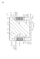
- the winding portion 62 is exposed from the non-magnetic layer 50 on the side surface 54 of the non-magnetic layer 50. As shown in FIGS. 1 and 3, in the present embodiment, the winding portion 62 is covered with the non-magnetic layer 50 on the side surface 53 of the non-magnetic layer 50.
- the magnetic core 40 is formed so as to cover a part of the non-magnetic layer 50 and the heat transfer member 30.
- the magnetic core 40 is formed so as to cover the upper surface 31a of the base plate 31.
- the magnetic core 40 is formed so as to expose the outer surfaces 34b and 35b of the heat radiating columns 34 and 35. Further, the magnetic core 40 is formed so as to expose the side surfaces 53 and 54 of the non-magnetic layer 50. Therefore, as shown in FIG. 2, the winding portion 62 is exposed from the side surface 54 of the non-magnetic layer 50 and the side surface 44 of the magnetic core 40.
- At least one of the outer surfaces 34b and 35b of the heat radiating columns 34 and 35 may be covered with a member other than the magnetic core 40, for example, a resin such as an adhesive. Further, at least one of the side surfaces 53 and 54 of the non-magnetic layer 50 may be covered with a member other than the magnetic core 40, for example, a resin such as an adhesive.
- the magnetic core 40 has a rectangular parallelepiped outer shape.
- the magnetic core 40 has an upper surface 41, a lower surface 42, and side surfaces 43, 44, 45, 46.
- the upper surface 41 of the magnetic core 40 constitutes the upper surface 11 of the reactor 1.
- the lower surface 42 of the magnetic core 40 is in contact with the upper surface 31a of the base plate 31 of the heat transfer member 30.
- the side surfaces 43, 44, 45, 46 of the magnetic core 40 constitute the side surfaces 13, 14, 15, 16 of the reactor 1.
- the magnetic core 40 has a fixing portion 47 protruding from the side surfaces 45 and 46.
- the fixing portion 47 has the same shape as the fixing portion 33 of the base plate 31 when viewed from above.
- the magnetic core 40 is formed of a mixture of magnetic powder and resin.
- the magnetic powder include Fe-based amorphous powder, nanocrystal material, Fe, Fe-Si-Al-based, Fe-Si-based, Fe-Ni-based, Fe-Co-based soft magnetic metal material and ferrite material powder. , Etc. can be used.
- the resin an epoxy resin, a silicone resin, or the like can be used.
- the magnetic core 40 is formed by molding such as injection molding, transfer molding, sheet pressing, or the like.
- the magnetic core 40 is formed by arranging the structure created up to the non-magnetic layer 50 in the mold and filling the mold with the above-mentioned material.
- the reactor 1 has a winding portion 62 formed by winding a wire rod, and has a coil 60 arranged so that the winding portion 62 is parallel to the lower surface 12 and a non-covering portion 62. It has a magnetic layer 50, a magnetic core 40 that covers the non-magnetic layer 50, and a heat transfer member 30 that transfers heat inside toward the lower surface 12.
- heat is generated at the winding portion 62 of the coil 60 by energizing the coil 60.
- the heat inside the reactor 1 is transferred toward the lower surface 12 of the reactor 1 by the heat transfer member 30, and the heat is dissipated to the heat radiating member or the like to which the reactor 1 is attached. In this way, efficient heat dissipation from the coil 60 is possible.
- the heat transfer member 30 has a base plate 31 and heat radiating columns 34 and 35 extending from the upper surface 31a of the base plate 31.
- the upper surfaces 34c and 35c of the heat radiating columns 34 and 35 are in close contact with the non-magnetic layer 50 that covers the winding portion 62 of the coil 60. That is, the tips of the heat radiating columns 34 and 35 extending upward from the base plate 31 are in contact with the non-magnetic layer 50. Therefore, the heat generated in the winding portion 62 is transferred to the base plate 31 via the non-magnetic layer 50 and the heat radiating columns 34 and 35, and is radiated from the base plate 31 to the outside of the reactor 1. Therefore, efficient heat dissipation from the coil 60 is possible.
- the outer surfaces 34b and 35b of the heat radiation columns 34 and 35 are exposed from the magnetic core 40. Therefore, the heat transferred by the heat radiating columns 34 and 35 is radiated from the outer surfaces 34b and 35b of the heat radiating columns 34 and 35 to the outside of the reactor 1. Therefore, efficient heat dissipation from the coil 60 is possible.
- the upper surfaces 34c and 35c of the heat radiating columns 34 and 35 of the heat transfer member 30 are in close contact with the non-magnetic layer 50.
- the heat radiation columns 34 and 35 support the non-magnetic layer 50 at a predetermined distance from the base plate 31.
- the magnetic core 40 is interposed between the base plate 31 and the non-magnetic layer 50. A magnetic path is formed by the magnetic core 40.
- the reactor 1 has a winding portion 62 formed by winding a wire rod, and has a coil 60 arranged so that the winding portion 62 is parallel to the lower surface 12 and a winding portion. It has a non-magnetic layer 50 that covers 62, a magnetic core 40 that covers the non-magnetic layer 50, and a heat transfer member 30 that transfers heat inside toward the lower surface 12.
- heat is generated at the winding portion 62 of the coil 60 by energizing the coil 60.
- the heat inside the reactor 1 is transferred toward the lower surface 12 of the reactor 1 by the heat transfer member 30, and the heat is dissipated to the heat radiating member or the like to which the reactor 1 is attached. In this way, efficient heat dissipation from the coil 60 is possible.
- the heat transfer member 30 has a base plate 31 and heat radiating columns 34 and 35 extending from the upper surface 31a of the base plate 31.
- the upper surfaces 34c and 35c of the heat radiating columns 34 and 35 are in close contact with the non-magnetic layer 50 that covers the winding portion 62 of the coil 60. That is, the tips of the heat radiating columns 34 and 35 extending upward from the base plate 31 are in contact with the non-magnetic layer 50. Therefore, the heat generated in the winding portion 62 is transferred to the base plate 31 via the non-magnetic layer 50 and the heat radiating columns 34 and 35, and is radiated from the base plate 31 to the outside of the reactor 1. Therefore, efficient heat dissipation from the coil 60 is possible.
- the configuration of the heat transfer member 30 is different from that of the first embodiment.
- the heat transfer member 30 will be described, and the same reference numerals will be given to other constituent members, and some or all of the description will be omitted.
- the heat transfer member 30 has a base plate 31 and a heat radiating column 36.
- the heat transfer member 30 has one heat dissipation column 36.
- the heat radiating column 36 is arranged inside the winding portion 62 of the coil 60 formed in an annular shape. As shown in FIG. 15, the heat radiating column 36 extends upward from the upper surface 31a of the base plate 31.
- the heat radiation column 36 of this embodiment is integrated with the base plate 31.
- the heat radiating column 36 extends above the non-magnetic layer 50.
- the heat radiation column 36 of the present embodiment extends to the vicinity of the upper surface 41 of the magnetic core 40, that is, to the vicinity of the upper surface 11 of the reactor 2.
- the heat of the central portion and the upper portion of the reactor 2 is transferred to the base plate 31 by the heat radiating column 36 extending to the vicinity of the upper surface 11 of the reactor 2, and the reactor 2 is transferred from the base plate 31 to the base plate 31. Can dissipate heat to the outside of.
- the heat transfer member 30 has a base plate 31 and a heat radiation column 36 extending upward from the base plate 31 inside the winding portion 62 of the coil 60.
- the heat radiating column 36 extending to the vicinity of the upper surface 11 of the reactor 2 transfers the heat of the central portion and the upper portion of the reactor 2 to the base plate 31, and can dissipate heat from the base plate 31 to the outside of the reactor 2. Therefore, the heat radiating column 36 constitutes a heat radiating path in which heat is directed to the lower surface 12 of the reactor 2 inside the winding portion 62 of the coil 60. As a result, the heat of the coil 60 can be efficiently dissipated.
- the configurations of the non-magnetic layer 50 and the heat transfer member 37 are different from those of the first embodiment.
- the non-magnetic layer 50 and the heat transfer member 37 will be described, and the same reference numerals will be given to other constituent members, and some or all of the description will be omitted.
- the non-magnetic layer 50 of the present embodiment has a core dividing portion 59 that divides the magnetic core 40 inside the winding portion 62.
- the core dividing portion 59 forms a magnetic gap 77 in the magnetic core 40. That is, the magnetic core 40 has a magnetic gap 77.
- the magnetic gap 77 relaxes the magnetic saturation in the reactor 2 and improves the DC superimposition characteristic.
- the non-magnetic layer 50 is formed by, for example, injection molding, transfer molding, sheet pressing, or other molding. Therefore, there is little variation in the thickness of the core dividing portion 59. Therefore, the thickness of the core dividing portion 59, that is, the magnetic gap 77 can be set accurately in the magnetic core 40.
- the magnetic core 40 is formed by arranging the structure created up to the non-magnetic layer 50 in the mold and filling the mold with the above-mentioned material. Therefore, the magnetic gap 77 of the magnetic core 40 is easily formed by the core dividing portion 59 of the non-magnetic layer 50. Therefore, the reactor 3 can be easily formed without the need for the magnetic core 40 to be manufactured by dividing it or the steps of combining the divided cores.
- the non-magnetic layer 50 of the present embodiment covers the winding portion 62 on the side surface 54. That is, the winding portion 62 is not exposed.
- the winding portion 62 may be exposed on the side surface 54. Further, the winding portion 62 may be exposed on the side surface 53.
- the heat transfer member 37 of this embodiment is a heat pipe and does not have a base plate. That is, the lower surface 12 of the reactor 3 is the lower surface 42 of the magnetic core 40.
- the reactor 3 dissipates heat from the lower surface 42 of the magnetic core 40 to a member such as a heat radiating member to which the reactor 3 is attached.
- the heat pipe transfers heat by the phase change of the working fluid.
- the heat transfer member 37 includes a cylindrical main body 37a extending in the vertical direction of the reactor 3 and having an upper end and a lower end sealed therein, and a working fluid 37b (see FIG. 22) sealed inside the main body 37a. have.
- the main body 37a is made of a substance having good thermal conductivity, for example, a metal such as copper.
- As the working fluid 37b it is preferable to use a fluid having a high vapor pressure and a large latent heat of vaporization.
- As the working fluid 37b for example, ammonia, water, chlorofluorocarbon, alcohol, acetone, or the like can be used.
- the main body 37a moves the liquefied working fluid upward.
- the heat transfer member 37 is arranged so as to penetrate the core dividing portion 59.
- the heat transfer member 37 transfers heat from the upper part of the magnetic core 40 toward the lower surface 42 of the magnetic core 40.
- the non-magnetic layer 50 has a core dividing portion 59 that divides the magnetic core 40 inside the winding portion 62.
- the core dividing portion 59 forms a magnetic gap 77 in the magnetic core 40. That is, the magnetic core 40 has a magnetic gap 77.
- the magnetic gap 77 can alleviate the magnetic saturation in the reactor 2 and improve the DC superimposition characteristic.
- the heat transfer member 37 is a heat pipe.
- the heat transfer member 37 extends in the vertical direction of the reactor 3.
- the heat transfer member 37 can transfer the heat of the upper part of the magnetic core 40 toward the lower surface 12 of the reactor 3 (the lower surface 42 of the magnetic core 40).
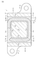
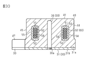
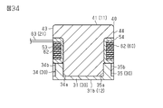
- the magnetic core 40 of the reactor 4 shown in FIGS. 25 to 27 covers substantially the entire non-magnetic layer 50.
- the non-magnetic layer 50 has annular protective portions 53a and 53b protruding from the side surface 53 at a portion where the lead wires 21 and 22 extend, so that the magnetic core 40 does not come into contact with the lead wires 21 and 22. ..
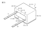
- the reactor 5 shown in FIG. 28 has a configuration in which the fixing portion 33 of the base plate 31 and the fixing portion 47 of the magnetic core 40 (see FIG. 1 and the like) are omitted.
- the reactor may be fixed by a separate member.
- the reactor 6 shown in FIGS. 29 and 30 is fixed to a member such as a heat radiating member by a fixing member 90.
- the base plate 31 has a fixing portion 33, and the fixing member 90 fixes the base plate 31 to a member such as a heat radiating member together with the fixing portion 33.
- the reactor having no fixed portion may be fixed to a member such as a heat radiating member by the fixing member 90.
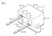
- the reactor 7 shown in FIGS. 31 and 32 includes annular protective portions 53a and 53b protruding from the side surface 53 in the non-magnetic layer 50 exposed from the side surface 43 of the magnetic core 40. .. In this reactor 7, the creepage distance from the magnetic core 40 to the lead wires 21 and 22 can be lengthened.
- the base plate 31 and the heat radiating column 36 may be separate bodies from the second embodiment.
- the heat radiating column 36 is fixed to the base plate 31 by a screw portion 36a formed at the lower end.
- a method of fixing the heat radiation column 36 a method such as welding can also be used.
- the material of the base plate 31 and the material of the heat radiating column 36 may be different from each other.
- the heat radiating columns 34 and 35 are embedded in the magnetic core 40, that is, the outer surfaces 34b and 35b of the heat radiating columns 34 and 35 are covered with the magnetic core 40. You may do so.
- the shape of the coil may be appropriately changed with respect to the above embodiment.
- a coil in which two winding portions 62 are connected in series may be used.
Landscapes
- Engineering & Computer Science (AREA)
- Power Engineering (AREA)
- Coils Of Transformers For General Uses (AREA)
Priority Applications (1)
| Application Number | Priority Date | Filing Date | Title |
|---|---|---|---|
| JP2022518628A JPWO2021220606A1 (https=) | 2020-04-28 | 2021-03-03 |
Applications Claiming Priority (2)
| Application Number | Priority Date | Filing Date | Title |
|---|---|---|---|
| JP2020079647 | 2020-04-28 | ||
| JP2020-079647 | 2020-04-28 |
Publications (1)
| Publication Number | Publication Date |
|---|---|
| WO2021220606A1 true WO2021220606A1 (ja) | 2021-11-04 |
Family
ID=78373615
Family Applications (1)
| Application Number | Title | Priority Date | Filing Date |
|---|---|---|---|
| PCT/JP2021/008107 Ceased WO2021220606A1 (ja) | 2020-04-28 | 2021-03-03 | リアクトル |
Country Status (2)
| Country | Link |
|---|---|
| JP (1) | JPWO2021220606A1 (https=) |
| WO (1) | WO2021220606A1 (https=) |
Citations (8)
| Publication number | Priority date | Publication date | Assignee | Title |
|---|---|---|---|---|
| JPH0476015U (https=) * | 1990-11-14 | 1992-07-02 | ||
| JP2001144478A (ja) * | 1999-11-18 | 2001-05-25 | Tdk Corp | トランスの放熱構造 |
| JP2008041882A (ja) * | 2006-08-04 | 2008-02-21 | Daikin Ind Ltd | リアクトル |
| JP2012160616A (ja) * | 2011-02-01 | 2012-08-23 | Denso Corp | トランス |
| US20150310976A1 (en) * | 2014-04-25 | 2015-10-29 | Delta Electronics (Shanghai) Co., Ltd. | Magnetic element |
| JP2015230914A (ja) * | 2014-06-03 | 2015-12-21 | 日産自動車株式会社 | トランス |
| US20160336109A1 (en) * | 2014-01-20 | 2016-11-17 | Tritium Holdings Pty Ltd | Transformer with improved heat dissipation |
| JP2019047105A (ja) * | 2017-03-27 | 2019-03-22 | Tdk株式会社 | コイル装置 |
-
2021
- 2021-03-03 JP JP2022518628A patent/JPWO2021220606A1/ja active Pending
- 2021-03-03 WO PCT/JP2021/008107 patent/WO2021220606A1/ja not_active Ceased
Patent Citations (8)
| Publication number | Priority date | Publication date | Assignee | Title |
|---|---|---|---|---|
| JPH0476015U (https=) * | 1990-11-14 | 1992-07-02 | ||
| JP2001144478A (ja) * | 1999-11-18 | 2001-05-25 | Tdk Corp | トランスの放熱構造 |
| JP2008041882A (ja) * | 2006-08-04 | 2008-02-21 | Daikin Ind Ltd | リアクトル |
| JP2012160616A (ja) * | 2011-02-01 | 2012-08-23 | Denso Corp | トランス |
| US20160336109A1 (en) * | 2014-01-20 | 2016-11-17 | Tritium Holdings Pty Ltd | Transformer with improved heat dissipation |
| US20150310976A1 (en) * | 2014-04-25 | 2015-10-29 | Delta Electronics (Shanghai) Co., Ltd. | Magnetic element |
| JP2015230914A (ja) * | 2014-06-03 | 2015-12-21 | 日産自動車株式会社 | トランス |
| JP2019047105A (ja) * | 2017-03-27 | 2019-03-22 | Tdk株式会社 | コイル装置 |
Also Published As
| Publication number | Publication date |
|---|---|
| JPWO2021220606A1 (https=) | 2021-11-04 |
Similar Documents
| Publication | Publication Date | Title |
|---|---|---|
| JP5343387B2 (ja) | リアクトル、及びコンバータ | |
| JP4924949B2 (ja) | リアクトル | |
| JPWO2017221804A1 (ja) | インダクタおよび当該インダクタの実装構造 | |
| US20180233281A1 (en) | Reactor and method for producing the same | |
| JP4973890B2 (ja) | リアクトル及びコイル成形体 | |
| JP6956484B2 (ja) | コイル装置および電力変換装置 | |
| JP2012209333A (ja) | リアクトル、およびリアクトルの製造方法 | |
| JP2009212384A (ja) | リアクトル及びリアクトルの取付構造 | |
| JP7022342B2 (ja) | リアクトル | |
| JP7130188B2 (ja) | リアクトル | |
| JP6744152B2 (ja) | コイル部品 | |
| WO2021220606A1 (ja) | リアクトル | |
| JP2017041497A (ja) | リアクトル | |
| JP7138752B2 (ja) | リアクトル | |
| JP6573079B2 (ja) | リアクトル | |
| JP2016096271A (ja) | リアクトル | |
| CN108630411B (zh) | 线圈装置 | |
| US20130299131A1 (en) | Adjustable heat dissipation assembly for magnetic devices | |
| JP7104897B2 (ja) | リアクトル | |
| JP6443635B2 (ja) | トランス及びトランスの製造方法 | |
| WO2021220598A1 (ja) | リアクトル | |
| WO2017029914A1 (ja) | リアクトル | |
| JP2011009791A (ja) | リアクトル | |
| JP7110863B2 (ja) | リアクトル | |
| JP7064718B2 (ja) | リアクトル |
Legal Events
| Date | Code | Title | Description |
|---|---|---|---|
| 121 | Ep: the epo has been informed by wipo that ep was designated in this application |
Ref document number: 21796466 Country of ref document: EP Kind code of ref document: A1 |
|
| ENP | Entry into the national phase |
Ref document number: 2022518628 Country of ref document: JP Kind code of ref document: A |
|
| NENP | Non-entry into the national phase |
Ref country code: DE |
|
| 122 | Ep: pct application non-entry in european phase |
Ref document number: 21796466 Country of ref document: EP Kind code of ref document: A1 |