WO2021214995A1 - 判定装置 - Google Patents
判定装置 Download PDFInfo
- Publication number
- WO2021214995A1 WO2021214995A1 PCT/JP2020/017750 JP2020017750W WO2021214995A1 WO 2021214995 A1 WO2021214995 A1 WO 2021214995A1 JP 2020017750 W JP2020017750 W JP 2020017750W WO 2021214995 A1 WO2021214995 A1 WO 2021214995A1
- Authority
- WO
- WIPO (PCT)
- Prior art keywords
- unit
- image data
- state
- determination
- time
- Prior art date
- Legal status (The legal status is an assumption and is not a legal conclusion. Google has not performed a legal analysis and makes no representation as to the accuracy of the status listed.)
- Ceased
Links
Images


Classifications
-
- G—PHYSICS
- G01—MEASURING; TESTING
- G01N—INVESTIGATING OR ANALYSING MATERIALS BY DETERMINING THEIR CHEMICAL OR PHYSICAL PROPERTIES
- G01N21/00—Investigating or analysing materials by the use of optical means, i.e. using sub-millimetre waves, infrared, visible or ultraviolet light
- G01N21/84—Systems specially adapted for particular applications
- G01N21/88—Investigating the presence of flaws or contamination
- G01N21/90—Investigating the presence of flaws or contamination in a container or its contents
- G01N21/9018—Dirt detection in containers
- G01N21/9027—Dirt detection in containers in containers after filling
-
- G—PHYSICS
- G01—MEASURING; TESTING
- G01N—INVESTIGATING OR ANALYSING MATERIALS BY DETERMINING THEIR CHEMICAL OR PHYSICAL PROPERTIES
- G01N21/00—Investigating or analysing materials by the use of optical means, i.e. using sub-millimetre waves, infrared, visible or ultraviolet light
- G01N21/84—Systems specially adapted for particular applications
- G01N21/88—Investigating the presence of flaws or contamination
- G01N21/8851—Scan or image signal processing specially adapted therefor, e.g. for scan signal adjustment, for detecting different kinds of defects, for compensating for structures, markings, edges
-
- G—PHYSICS
- G01—MEASURING; TESTING
- G01N—INVESTIGATING OR ANALYSING MATERIALS BY DETERMINING THEIR CHEMICAL OR PHYSICAL PROPERTIES
- G01N21/00—Investigating or analysing materials by the use of optical means, i.e. using sub-millimetre waves, infrared, visible or ultraviolet light
- G01N21/84—Systems specially adapted for particular applications
- G01N21/88—Investigating the presence of flaws or contamination
- G01N21/90—Investigating the presence of flaws or contamination in a container or its contents
-
- G—PHYSICS
- G06—COMPUTING OR CALCULATING; COUNTING
- G06T—IMAGE DATA PROCESSING OR GENERATION, IN GENERAL
- G06T7/00—Image analysis
- G06T7/0002—Inspection of images, e.g. flaw detection
-
- G—PHYSICS
- G06—COMPUTING OR CALCULATING; COUNTING
- G06T—IMAGE DATA PROCESSING OR GENERATION, IN GENERAL
- G06T7/00—Image analysis
- G06T7/0002—Inspection of images, e.g. flaw detection
- G06T7/0004—Industrial image inspection
- G06T7/0008—Industrial image inspection checking presence/absence
-
- G—PHYSICS
- G06—COMPUTING OR CALCULATING; COUNTING
- G06T—IMAGE DATA PROCESSING OR GENERATION, IN GENERAL
- G06T7/00—Image analysis
- G06T7/20—Analysis of motion
-
- G—PHYSICS
- G06—COMPUTING OR CALCULATING; COUNTING
- G06T—IMAGE DATA PROCESSING OR GENERATION, IN GENERAL
- G06T2207/00—Indexing scheme for image analysis or image enhancement
- G06T2207/10—Image acquisition modality
- G06T2207/10016—Video; Image sequence
-
- G—PHYSICS
- G06—COMPUTING OR CALCULATING; COUNTING
- G06T—IMAGE DATA PROCESSING OR GENERATION, IN GENERAL
- G06T2207/00—Indexing scheme for image analysis or image enhancement
- G06T2207/10—Image acquisition modality
- G06T2207/10141—Special mode during image acquisition
- G06T2207/10152—Varying illumination
-
- G—PHYSICS
- G06—COMPUTING OR CALCULATING; COUNTING
- G06T—IMAGE DATA PROCESSING OR GENERATION, IN GENERAL
- G06T2207/00—Indexing scheme for image analysis or image enhancement
- G06T2207/20—Special algorithmic details
- G06T2207/20021—Dividing image into blocks, subimages or windows
Definitions
- the present invention relates to a determination device, a determination method, a recording medium, and a determination system.
- the technology for detecting foreign substances in the liquid contained in the container is known.
- Patent Document 1 is one of the techniques used when detecting a foreign substance.
- Patent Document 1 describes a first irradiation source for irradiating the container with the first irradiation light, a second irradiation source for irradiating the container with the second irradiation light from a direction different from the first irradiation light, and imaging.
- a foreign matter detection device having means and inspection means is described.
- the imaging means captures the transmitted light on the transmitted light path of the first irradiation light from the container and the diffusely reflected light of the second irradiation light. Then, the inspection means detects the foreign matter in the filling liquid based on the image acquired by the imaging means.
- Patent Document 1 discloses that the first irradiation light and the second irradiation light are irradiated in different time zones.
- an object of the present invention is to provide a determination device, a determination method, a recording medium, and a determination system that solve the problem that foreign matter may not be detected accurately and efficiently.
- the determination device which is one form of the present disclosure, in order to achieve such an object
- a division unit that divides the time-series image data acquired by photographing the liquid filled in the container while switching a plurality of lighting conditions into time-series image data according to the lighting conditions.
- a determination unit that determines foreign matter mixed in the inside of the container based on each of the time-series image data divided by the division unit, and a determination unit. It has a structure of having.
- Judgment device The time-series image data acquired by photographing the liquid filled in the container while switching a plurality of lighting conditions is divided into time-series image data according to the lighting conditions. Based on each of the divided time-series image data, the foreign matter mixed in the inside of the container is determined.
- the recording medium which is another form of the present disclosure is For the judgment device, A division unit that divides the time-series image data acquired by photographing the liquid filled in the container while switching a plurality of lighting conditions into time-series image data according to the lighting conditions. A determination unit that determines foreign matter mixed in the inside of the container based on each of the time-series image data divided by the division unit, and a determination unit. It is a computer-readable recording medium on which a program for realizing the above is recorded.
- a first illumination unit that irradiates the image pickup device that acquires image data with light so that the transmitted light transmitted through the container is incident.
- a second illumination unit that irradiates the image pickup device that acquires image data with light so that the transmitted light transmitted through the container does not enter.
- the liquid filled in the container is photographed in an environment in which a plurality of lighting conditions including the first state in which the first lighting unit irradiates light and the second state in which the second lighting unit irradiates light are switched.
- a determination device having a determination unit for determining a foreign substance mixed in, and a determination device. It has a structure of having.
- FIG. 1st Embodiment of this disclosure It is a figure which shows the structural example of the determination system in 1st Embodiment of this disclosure. It is a figure which shows an example of the positional relationship between a container and lighting. It is a figure for demonstrating the lighting example of lighting. It is a figure for demonstrating the lighting example of lighting. It is a block diagram which shows the structural example of the lighting control device. It is a figure which shows the lighting control example by a lighting control device. It is a figure which shows the lighting control example by a lighting control device. It is a block diagram which shows the structural example of the determination apparatus. It is a figure which shows an example of image information. It is a figure which shows the processing example of the division part.
- FIG. 1 is a diagram showing a configuration example of the determination system 100.
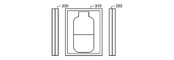
- FIG. 2 is a diagram showing an example of the positional relationship between the container 700 and the lighting.
- 3 and 4 are diagrams for explaining a lighting example of lighting.
- FIG. 5 is a block diagram showing a configuration example of the lighting control device 400.
- 6 and 7 are diagrams showing an example of lighting control by the lighting control device 400.
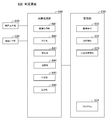
- FIG. 8 is a block diagram showing a configuration example of the determination device 600.
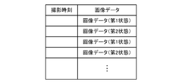
- FIG. 9 is a diagram showing an example of image information 631.
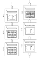
- FIG. 10 is a diagram showing a processing example of the division unit 642.
- FIG. 11 is a flowchart showing an operation example of the determination device 600.
- FIG. 12 is a flowchart showing a processing example of the determination unit 645.
- FIG. 13 is a diagram showing an example of another positional relationship between the container 700 and the lighting.
- a determination system 100 that detects an object mixed in a container 700 filled with a liquid such as water or a chemical and determines a foreign substance among the detected objects will be described.
- the determination system 100 acquires time-series image data by taking a picture with the camera 500 while switching a plurality of lighting conditions. For example, the determination system 100 switches between a state in which the container 700 is irradiated with light from the first illumination unit 310 and a state in which the container 700 is irradiated with light from the second illumination unit 320 at predetermined intervals. , Acquire time-series image data. Then, the determination system 100 divides the acquired time-series image data into time-series image data corresponding to each state, and then determines a foreign substance based on each of the divided time-series image data.
- the foreign matter to be determined includes a foreign matter that transmits light such as a glass piece and a foreign matter that does not transmit light such as a rubber piece and hair.
- a piece of glass which is a foreign substance that transmits light, has a heavier specific gravity than a foreign substance that does not transmit light, such as a rubber piece or hair. Sink.
- the side filled with the liquid in the container 700 is defined as the upper side, and the opposite side is defined as the lower side.
- the liquid filled inside the container 700 is collected under the container 700.
- FIG. 1 is a side view showing an overall configuration example of the determination system 100.
- the determination system 100 includes, for example, a gripping device 200, a first illumination unit 310, a second illumination unit 320, an illumination control device 400, a camera 500, and a determination device 600.
- the first lighting unit 310 and the lighting control device 400 are connected so as to be able to communicate with each other.
- the second lighting unit 320 and the lighting control device 400 are connected so as to be able to communicate with each other.
- the camera 500 and the determination device 600 are connected so as to be able to communicate with each other.
- the lighting control device 400 and the camera 500 can be connected so as to be able to communicate with each other.
- the gripping device 200 is a device that grips the container 700.
- the gripping device 200 includes an upper grip portion that projects downward and abuts on the upper side of the container 700, and a lower grip portion that projects upward and abuts on the lower side of the container 700.
- the upper gripping portion of the gripping device 200 abuts on the container 700 from the upper side of the container 700
- the lower gripping portion abuts on the container 700 from the lower side of the container 700, whereby the gripping device 200 ,
- the container 700 is sandwiched from above and below to grip the container 700.
- the gripping device 200 may grip the container 700 by a method other than the above-exemplified method.
- the gripping device 200 can tilt or rotate the container 700 while sandwiching and gripping the container 700. By tilting or rotating the container 700 while the gripping device 200 sandwiches the container 700, foreign matter settled inside the container 700 can be lifted up.
- the configuration for the gripping device 200 to incline or rotate the container 700 is not particularly limited.
- the gripping device 200 may be configured to tilt or rotate the container 700 using known methods.
- the first lighting unit 310 irradiates the liquid filled in the container 700 with light according to the control from the lighting control device 400.
- FIG. 1 shows an example of the positional relationship between the first illumination unit 310, the second illumination unit 320, and the container 700 when viewed from the side surface direction
- FIG. 2 shows the first illumination unit 310 when viewed from the shooting direction of the camera 500.
- An example of the positional relationship between the second lighting unit 320 and the container 700 is shown.
- the first lighting unit 310 is installed on the side opposite to the side on which the camera 500 is installed when viewed from the container 700 and the gripping device 200. According to such a configuration, the first illumination unit 310 irradiates the camera 500 with light through the container 700.
- the transmitted light transmitted through the container 700 is incident on the camera 500.
- the transmitted light at the location where the foreign substance is present is blocked by the foreign substance that does not transmit light.
- black circles represent foreign substances that do not transmit light.
- the first lighting unit 310 has a shutter curtain using a liquid crystal display or the like.
- the shutter curtain included in the first illumination unit 310 closes when the first illumination unit 310 is not irradiating light. Therefore, it can be said that the first illumination unit 310 can take two states, a lighting state of irradiating light and an extinguishing state of closing the shutter curtain.
- the second lighting unit 320 irradiates the liquid filled in the container 700 with light according to the control from the lighting control device 400.
- the second lighting unit 320 is installed on, for example, a side surface of the container 700. According to such a configuration, the second illumination unit 320 irradiates light from the side surface direction of the container 700.
- the transmitted light transmitted through the container 700 is not directly incident on the camera 500.
- the foreign substance that transmits light is present inside the container 700, the foreign substance that transmits light existing in the container 700 diffusely reflects the light. Therefore, as shown in FIG.
- the second illumination unit 320 irradiates the light, so that the diffusely reflected light diffusely reflected by the foreign substance is incident on the camera 500.
- white circles represent foreign substances that transmit light.
- the second lighting unit 320 can have a shutter curtain using a liquid crystal display or the like.
- the shutter curtain of the second lighting unit 320 closes when the second lighting unit 320 is not irradiating light, as in the case of the first lighting unit 310. That is, it can be said that the second lighting unit 320 can take two states, a lighting state of irradiating light and an extinguishing state of closing the shutter curtain.
- the second lighting unit 320 does not have to have a shutter curtain.
- the installation position of the second lighting unit 320 is not limited to the cases illustrated in FIGS. 1 and 2.
- the second illuminating unit 320 is located at a position other than those illustrated in FIGS. 1 and 2 such as diagonally rearward if the transmitted light radiated by the second illuminating unit 320 and transmitted through the container 700 does not directly enter the camera 500. It may be installed.
- the lighting control device 400 is a control device that switches lighting conditions by controlling the lighting state and the extinguishing state of the first lighting unit 310 and the second lighting unit 320.
- FIG. 5 shows a configuration example of the lighting control device 400. Referring to FIG. 5, the lighting control device 400 has, for example, a control unit 410.
- the lighting control device 400 has, for example, an arithmetic unit such as a CPU and a storage device.
- the lighting control device 400 realizes the processing unit by executing a program stored in the storage device by the arithmetic unit.
- the lighting control device 400 may realize the above-mentioned processing unit by hardware.
- the control unit 410 controls the state of the first lighting unit 310 and the second lighting unit 320 by transmitting a lighting instruction to the first lighting unit 310 and the second lighting unit 320.
- the first lighting unit 310 is in the lighting state and the second lighting unit 320 is in the extinguishing state at the same time, or the first lighting unit 310 is in the extinguishing state at the same time.
- the state of the first lighting unit 310 and the second lighting unit 320 is controlled so that the lighting unit 320 becomes one of the second states in which the lighting unit 320 is in the lighting state.
- the illumination condition is in the first state
- the transmitted light transmitted through the container 700 is incident on the camera 500.
- the illumination condition is in the second state, the transmitted light transmitted through the container 700 does not enter the camera 500.
- control unit 410 controls the state of the first lighting unit 310 and the second lighting unit 320 so that the lighting intervals of the first lighting unit 310 and the second lighting unit 320 are synchronized with the shooting interval of the camera 500. Can be done. In other words, the control unit 410 can control the first illumination unit 310 and the second illumination unit 320 so as to switch between the first state and the second state at intervals according to the shooting interval of the camera 500. For example, as will be described later, the camera 500 acquires image data at a high frame rate of about 150 to 200 fps.
- control unit 410 sets the first illumination unit 310 and the second illumination unit 320 so as to switch between the first state and the second state at intervals of 0.005 seconds to 0.0067 seconds or a multiple thereof. It can be controlled.
- the control unit 410 may be configured to send and receive necessary information for synchronizing the intervals with the camera 500.
- FIG. 6 shows an example of control by the control unit 410.
- the control unit 410 controls the states of the first lighting unit 310 and the second lighting unit 320 so that the first state and the second state are switched each time the camera 500 takes a picture. Can be done.
- the control unit 410 controls the states of the first lighting unit 310 and the second lighting unit 320 so that the first state and the second state are switched at equal intervals such as every 0.005 seconds to 0.0067 seconds. Can be done.
- control unit 410 can be configured to change the interval for switching between the first state and the second state with the passage of time.
- FIG. 7 shows another control example by the control unit 410.
- the control unit 410 continues the second state until the camera 500 shoots twice, and then switches to the first state.
- the control unit 410 keeps the second state for 0.01 seconds to 0.013 seconds, and then sets the first state for 0.005 seconds to 0.0067 seconds.
- the control unit 410 continues such switching for a predetermined time. Subsequently, the control unit 410 continues the process of switching between the first state and the second state at equal intervals for a predetermined time.
- the control unit 410 continues the first state for 0.01 seconds to 0.013 seconds, and then switches to the second state for 0.005 seconds to 0.0067 seconds for a predetermined time. In this way, the control unit 410 can change the switching interval so that the second state is made longer than the first state immediately after the start of shooting, while the first state is made longer than the second state with the passage of time. You can. In addition, after continuing the second state for 0.015 seconds to 0.02 seconds, the control unit 410 sets the first state and the second state, such as setting the first state for 0.005 seconds to 0.0067 seconds. The switching interval may be changed arbitrarily.
- the time for switching in the second state to be longer than that in the first state, the time for switching at equal intervals, the time for switching in the first state to be longer than that in the second state, and the respective times are also arbitrary. You can set it.
- a glass piece or the like which is a foreign substance that transmits light, has a heavier specific gravity than a foreign substance that does not transmit light, such as a rubber piece or hair, and is in a state of flying up in the liquid filled inside the container 700. Sinks to the bottom sooner.
- the proportion of the second stage suitable for detecting foreign matter that transmits light at an early stage after the start of imaging is increased, and the ratio of the first stage suitable for detecting foreign matter that does not transmit light with the passage of time is increased. By increasing the ratio, it becomes possible to perform detection according to the characteristics of the foreign matter.
- control unit 410 can control the states of the first lighting unit 310 and the second lighting unit 320 so that the first state and the second state are switched at predetermined intervals. ..
- the camera 500 is an imaging device that acquires image data by photographing the container 700. For example, the camera 500 starts taking image data after tilting the container 700 or the like. As shown in FIG. 1, the camera 500 is preliminarily installed at a predetermined position on the side opposite to the side where the first illumination unit 310 is located when viewed from the gripping device 200. The camera 500 may be configured to send and receive necessary information for synchronizing the intervals to and from the lighting control device 400.
- the camera 500 continuously acquires image data at a high frame rate of about 150 to 200 fps. Then, the camera 500 transmits the acquired image data to the determination device 600 together with information indicating the shooting time and the like.
- the camera 500 may acquire image data at a frame rate other than those illustrated above.
- the states of the first lighting unit 310 and the second lighting unit 320 are controlled by the lighting control device 400. Therefore, the time-series image data acquired by the camera 500 includes the image data captured in the first state and the second image data captured in the first state, such as the image data captured in the first state and the image data captured in the second state alternately existing. The image data taken in the state is mixed.
- the determination device 600 is an information processing device that detects an object mixed in the container 700 filled with the liquid and determines a foreign substance based on the image data captured and acquired by the camera 500.
- FIG. 8 shows a configuration example of the determination device 600. Referring to FIG. 8, the determination device 600 has, for example, a screen display unit 610, a communication I / F unit 620, a storage unit 630, and an arithmetic processing unit 640 as main components.
- the screen display unit 610 is composed of a screen display device such as an LCD (Liquid Crystal Display).
- the screen display unit 610 can display various information stored in the storage unit 630 such as image information 631, tracking information 632, and determination result information 633 on the screen in response to an instruction from the arithmetic processing unit 640.
- the communication I / F unit 620 is composed of a data communication circuit.
- the communication I / F unit 620 performs data communication with a camera 500, an external device, or the like connected via a communication line.
- the storage unit 630 is a storage device such as a hard disk or a memory.
- the storage unit 630 stores processing information and a program 634 required for various processes in the arithmetic processing unit 640.
- the program 634 realizes various processing units by being read and executed by the arithmetic processing unit 640.
- the program 634 is read in advance from an external device or a recording medium via a data input / output function such as the communication I / F unit 620, and is stored in the storage unit 630.
- the main information stored in the storage unit 630 includes, for example, image information 631, tracking information 632, determination result information 633, and the like.
- the image information 631 includes time-series image data acquired by the camera 500.
- the image data and the information indicating the date and time when the camera 500 acquired the image data are associated with each other.
- FIG. 9 shows an example of time-series image data included in the image information 631.
- the image information 631 contains a mixture of image data captured in the first state and image data captured in the second state.
- the lighting control device 400 switches between the first state and the second state. Therefore, the image data stored as the image information 631 includes the image data captured in the first state and the image data captured in the second state, such that the image data captured in the first state and the image data captured in the second state alternately exist.
- the image data taken in is mixed with the image data taken in.
- the tracking information 632 includes information according to the result of tracking by the tracking unit 644, which will be described later.
- the identification information given for each object and the time-series information indicating the position of the object are associated with each other.
- the time-series information indicating the position of the object includes, for example, time information and position information such as coordinates indicating the position of the object at each time.
- the tracking unit 644 uses the time-series image data included in the image information 631 by the dividing unit 642 as the time-series image data captured in the first state and the time-series captured in the second state. After dividing into image data, tracking is performed based on each time-series data after division. Therefore, the tracking information 632 includes information according to the result of tracking using the time-series data corresponding to the first state and the result of tracking using the time-series data corresponding to the second state. Information and is included.
- the tracking information 632 may include information other than the position of the object as illustrated above.
- the tracking information 632 may include information indicating the area of the detection area.
- the determination result information 633 includes information indicating the result of the determination by the determination unit 645.
- the identification information given for each object is associated with the information indicating the result of determination by the determination unit 645 based on the tracking information 632. That is, the determination result information 633 includes information indicating which of the foreign substances, air bubbles, scratches and stains on the container corresponds to the detected object.
- the arithmetic processing unit 640 has a microprocessor such as an MPU and its peripheral circuits.
- the arithmetic processing unit 640 reads the program 634 from the storage unit 630 and executes it, thereby realizing various processing units in cooperation with the hardware and the program 634.
- the main processing units realized by the arithmetic processing unit 640 include, for example, an image acquisition unit 641, a division unit 642, a detection unit 643, a tracking unit 644, a determination unit 645, and an output unit 646.
- the image acquisition unit 641 acquires the image data acquired by the camera 500 from the camera 500 via the communication I / F unit 620. Then, the image acquisition unit 641 stores the acquired image data in the storage unit 630 as image information 631 in association with, for example, the acquisition date and time (information indicating the shooting time) of the image data.
- the dividing unit 642 divides the time-series image data included in the image information 631 into time-series image data taken in the first state and time-series image data taken in the second state.
- the determination device 600 has information indicating under what conditions (at what intervals) the lighting control device 400 switches between the first state and the second state. Therefore, the division unit 642 uses the above information to obtain the time-series image data included in the image information 631 with the time-series image data captured in the first state based on the time corresponding to the image data. It is divided into time-series image data taken in two states.
- FIG. 10 is a diagram for explaining an example of the division process by the division unit 642.
- the division unit 642 captures the image information 631 in a state in which the image data captured in the first state and the image data captured in the second state are mixed, and is a time-series image captured in the first state. It is divided into data and time-series image data taken in the second state.
- the division unit 642 may divide the time-series image data based on information other than the time. For example, when the dividing unit 642 captures time-series image data in the second state and the time-series image data captured in the first state based on the ratio of light and darkness when the image data is binarized. It may be divided into a series of image data. The division unit 642 may perform the division processing by combining the methods exemplified above.
- the detection unit 643 detects an object existing in the container 700 or the region corresponding to the liquid filled in the container 700 based on the image data. For example, the detection unit 643 performs binarization processing on the image data and detects an object based on the result of the binarization processing. The detection unit 643 may detect the object by using other known techniques.
- the detection unit 643 detects an object from each of the time-series image data captured in the first state divided by the division unit 642, and also from each of the time-series image data captured in the second state. Detect an object. As shown in FIG. 3, in the first state, while the transmitted light is incident on the camera 500, the transmitted light at the portion where the foreign matter is present is blocked by the foreign matter that does not transmit the light. Therefore, the detection unit 643 can mainly detect an object containing a foreign substance that does not transmit light, based on the image data taken in the first state. On the other hand, as shown in FIG.
- the detection unit 643 can detect an object containing a foreign substance that mainly transmits light, based on the image data taken in the second state.
- the tracking unit 644 tracks the object detected by the detection unit 643. As described above, the camera 500 acquires image data at a high frame rate such as 200 fps. Therefore, it is assumed that the positions of the same objects are extremely close to each other between two image data in which the shooting times are continuous (the shooting times are closer than a predetermined value). Therefore, the tracking unit 644 compares the position of the object detected by the detection unit 643 with the position of the object detected by the detection unit 643 in the image data one before (or within a predetermined value) the shooting time.
- the tracking unit 644 when there is an object in which the distance between the objects is equal to or less than a predetermined threshold value, the tracking unit 644 has image data in which the distance is equal to or less than the threshold value and the object detected by the detection unit 643 and the shooting time are one before. It is determined that the object detected by the detection unit 643 is the same object. In this case, the tracking unit 644 adds identification information such as an ID given to the object determined to be the same object to the object detected by the detection unit 643. On the other hand, in the image data one before the shooting time (or within a predetermined value), when there is no object whose distance from the object detected by the detection unit 643 is equal to or less than a predetermined threshold value, the tracking unit 644 Determines that a new object has been detected. In this case, the tracking unit 644 adds identification information such as a new ID to the detected object.
- the tracking unit 644 provides identification information to the object detected by the detection unit 643 by performing tracking based on the distance between the objects in different image data. Further, the tracking unit 644 acquires the coordinates indicating the position of the object detected by the detection unit 643. Then, the tracking unit 644 associates the identification information with the time information indicating the shooting time of the image data and the coordinates, and stores the tracking information 632 in the storage unit 630.
- the tracking unit 644 tracks the tracking based on the time-series image data captured in the first state and the tracking based on the time-series image data captured in the second state, which is divided by the dividing unit 642. And do. That is, the tracking unit 644 compares the positions based on the time-series image data captured in the first state, and also compares the positions based on the time-series image data captured in the second state.
- the detection unit 643 mainly detects an object containing a foreign substance that does not transmit light, based on the image data taken in the first state.
- the tracking unit 644 can track an object containing a foreign substance that does not mainly transmit light, based on the time-series image data taken in the first state.
- the detection unit 643 detects an object containing a foreign substance that mainly transmits light, based on the image data taken in the second state. Therefore, the tracking unit 644 can track an object containing a foreign substance that mainly transmits light, based on the time-series image data taken in the second state.
- the determination unit 645 determines whether the object detected by the detection unit 643 corresponds to a bubble or a foreign substance based on the tracking information 632. Then, the determination unit 645 stores the determination result of each object detected by the detection unit 643 in the storage unit 630 as the determination result information 633.
- the determination unit 645 determines that the object is moving upward based on the tracking information 632, the determination unit 645 determines that the object is a bubble.
- the determination unit 645 determines that the object is moving downward based on the tracking information 632, the determination unit 645 determines that the object is a foreign substance.
- the determination unit 645 can determine whether the object is a bubble or a foreign substance by determining the moving direction of the object based on the tracking information 632.
- the determination unit 645 may determine the air bubbles and the foreign matter by a method other than the above-exemplified method, such as performing the above determination using a model learned in advance.
- the tracking information 632 includes information according to the result of tracking using the time-series data corresponding to the first state and tracking using the time-series data corresponding to the second state. Information according to the result of the work is included. Therefore, the determination unit 645 is either a bubble or a foreign substance that does not transmit light, based on the information according to the result of tracking using the time-series data corresponding to the first state of the tracking information 632. You may judge whether or not. Similarly, the determination unit 645 is based on the information according to the result of tracking using the time-series data corresponding to the second state of the tracking information 632, and the object is either a bubble or a foreign substance that transmits light. It may be determined whether or not there is. In this way, the determination unit 645 can determine whether the object is a bubble or a foreign substance, and can determine whether or not the foreign substance transmits light.
- the determination unit 645 may use information other than the tracking information 632 when determining the object.
- the determination unit 645 can determine an object by using information indicating an image feature, size, average luminance value, and the like of the object together. By also judging information other than movement such as the size of the object and the average brightness value, the characteristics of bubbles and foreign substances can be comprehensively judged, so that higher judgment accuracy can be obtained.
- the output unit 646 outputs image information 631, tracking information 632, determination result information 633, and the like.
- the output unit 646 displays the image information 631, the tracking information 632, the determination result information 633, and the like on the screen display unit 610, or transmits the image information 631, the tracking information 632, the determination result information 633, and the like to the external device via the communication I / F unit 620. Can be done.
- the above is a configuration example of the determination device 600.
- the determination device 600 may have a configuration other than the above.
- the determination device 600 can be configured to instruct the gripping device 200 to tilt / rotate or stop tilting / rotating.
- the container 700 is a translucent container such as a glass bottle or a PET bottle.
- the inside of the container 700 is filled with a liquid such as water or a chemical.
- Foreign matter may be mixed inside the container 700.
- foreign matter for example, foreign matter that does not transmit light such as rubber pieces, hair, fiber pieces, and soot, and foreign matter that transmits light such as glass and plastic pieces are assumed.
- the above is a configuration example of the gripping device 200, the first lighting unit 310, the second lighting unit 320, the lighting control device 400, the camera 500, and the judgment device 600 included in the determination system 100. Subsequently, an operation example of the determination device 600 will be described with reference to FIGS. 11 and 12.
- the image acquisition unit 641 acquires the image data acquired by the camera 500 from the camera 500 via the communication I / F unit 620 (step S101).
- the image acquisition unit 641 acquires time-series image data in a state in which the image data captured in the first state and the image data captured in the second state are mixed.
- the dividing unit 642 divides the time-series image data into the time-series image data taken in the first state and the time-series image data taken in the second state (step S102).
- the determination device 600 has information indicating under what conditions (at what intervals) the lighting control device 400 switches between the first state and the second state.
- the dividing unit 642 divides the time-series image data included in the image information 631 into time-series image data taken in the first state and time-series image data taken in the second state. do.
- the dividing unit 642 may perform the dividing process by using a method other than the above-exemplified method.
- the detection unit 643 detects an object existing in the container 700 or the region corresponding to the liquid filled in the container 700 based on the time-series image data taken in the first state. (Step S111). In the process of step S111, the detection unit 643 mainly detects an object containing a foreign substance that does not transmit light. The detection unit 643 may detect an object using a known technique.
- the tracking unit 644 tracks the object detected by the detection unit 643 (step S112). That is, the tracking unit 644 mainly tracks an object including a foreign substance that does not transmit light. For example, the tracking unit 644 tracks an object based on the distance between the objects in the image data whose shooting times are close (or continuous).
- step S113, No If all the objects detected by the detection unit 643 cannot be tracked in the image data (step S113, No), the tracking unit 644 tracks the objects that are not being tracked. On the other hand, when all the objects detected by the detection unit 643 can be tracked in the image data (step S113, Yes), the tracking unit 644 completes the tracking based on the image data.
- step S114, Yes When tracking is completed for all the time-series image data captured in the first state divided by the dividing unit 642 (step S114, Yes), the determination device 600 processes based on the time-series image data captured in the first state. To finish. On the other hand, when there is undetected or untracked image data (step S114, No), the determination device 600 continues the detection by the detection unit 643 and the tracking by the tracking unit 644.
- the detection unit 643 detects an object existing in the container 700 or the region corresponding to the liquid filled in the container 700 based on the time-series image data taken in the second state. (Step S121). In the process of step S121, the detection unit 643 mainly detects an object containing a foreign substance that transmits light. The detection unit 643 may detect an object using a known technique.
- the tracking unit 644 tracks the object detected by the detection unit 643 (step S122). That is, the tracking unit 644 mainly tracks an object including a foreign substance that transmits light. For example, the tracking unit 644 tracks an object based on the distance between the objects in the image data whose shooting times are close (or continuous).
- step S123, No If all the objects detected by the detection unit 643 cannot be tracked in the image data (step S123, No), the tracking unit 644 tracks the objects that are not being tracked. On the other hand, when all the objects detected by the detection unit 643 can be tracked in the image data (step S123, Yes), the tracking unit 644 completes the tracking based on the image data.
- step S124, Yes When tracking is completed for all the time-series image data captured in the second state divided by the dividing unit 642 (step S124, Yes), the determination device 600 processes based on the time-series image data captured in the second state. To finish. On the other hand, when there is undetected or untracked image data (step S124, No), the determination device 600 continues the detection by the detection unit 643 and the tracking by the tracking unit 644.
- step S111 to step S114 and the processing from step S121 to step S124 may be performed in parallel. Subsequently, a processing example of the determination unit 645 will be described with reference to FIG.
- the determination unit 645 acquires the tracking information 632 (step S201).
- the determination unit 645 determines whether the object detected by the detection unit 643 is a bubble or a foreign substance based on the tracking information 632 (step S202). For example, the determination unit 645 can determine whether the object is a bubble or a foreign substance based on the moving direction of the object. The determination unit 645 may make a determination by a method other than the above-exemplified method. The determination unit 645 may determine whether the object is a bubble or a foreign substance, and may determine whether the foreign substance is a foreign substance that transmits light or a foreign substance that does not transmit light.
- the above is a processing example of the determination unit 645.
- the determination device 600 has a division unit 642, a detection unit 643, a tracking unit 644, and a determination unit 645.
- the tracking unit 644 tracks the object detected by the detection unit 643 based on the time-series image data captured in the first state divided by the division unit 642, and when the object is photographed in the second state. It is possible to track the object detected by the detection unit 643 based on the image data of the series.
- the determination unit 645 can make a determination based on the result of tracking by the tracking unit 644.
- detection, tracking, and determination are performed by a method suitable for a foreign substance that transmits light
- detection, tracking, and determination are performed by a method suitable for a foreign substance that does not transmit light. Can be done. As a result, foreign matter can be detected accurately and efficiently.
- the determination system 100 can have a third illumination unit 330.
- the third lighting unit 330 irradiates the liquid filled in the container 700 with light at the same intervals as the second lighting unit 320.
- the third lighting unit 330 can be installed, for example, in the side surface direction of the container 700 and on the side opposite to the installation position of the second lighting unit 320 when viewed from the container 700.
- the determination system 100 may have a plurality of lights.
- the function as the determination device 600 is realized by one information processing device has been described.
- the function as the determination device 600 may be realized by a plurality of information processing devices connected via a network.
- the determination system 100 includes a lighting control device 400 and a determination device 600.
- the determination device 600 may have a function as the lighting control device 400. That is, the lighting control device 400 and the determination device 600 can be integrally configured.
- the determination device 600 has a function as the lighting control device 400, the determination system 100 does not have to have an individual lighting control device 400.
- the first lighting unit 310 is in the lighting state of the first lighting unit 310 and the second lighting unit 320 is in the extinguishing state at the same time, and the first lighting unit 310 is in the extinguishing state at the same time. Is in the extinguished state and the second illuminating unit 320 is in the lit state.
- the lighting conditions are not necessarily limited to the cases illustrated in this embodiment.
- the lighting conditions include a state in which the first lighting unit 310 is in the lighting state and the second lighting unit 320 is in the lighting state at the same time, and the first lighting unit 310 and the second lighting unit 320 are in the extinguishing state.
- a state other than the above-exemplified state may be included, such as the third lighting unit 330 being in the lighting state. Further, for example, the state in which the first lighting unit 310 is in the lighting state and the second lighting unit 320 is in the lighting state and the state in which the first lighting unit 310 is in the extinguishing state and the second lighting unit 320 is in the lighting state are switched. , Switching other than those illustrated in this embodiment may be performed.
- FIG. 14 shows a hardware configuration example of the determination device 800.
- the determination device 800 has the following hardware configuration as an example.
- -CPU Central Processing Unit
- 801 Arimetic unit
- ROM Read Only Memory
- RAM Random Access Memory
- 803 storage device
- -Program group 804 loaded in RAM 803
- a storage device 805 that stores the program group 804.
- -Drive device 806 that reads and writes the recording medium 810 external to the information processing device.
- -Communication interface 807 that connects to the communication network 811 outside the information processing device -I / O interface 808 that inputs and outputs data -Bus 809 connecting each component
- the determination device 800 can realize the functions as the division unit 821 and the determination unit 822 shown in FIG. 15 by the CPU 801 acquiring the program group 804 and executing the program group 801.
- the program group 804 is stored in the storage device 805 or the ROM 802 in advance, for example, and the CPU 801 loads the program group 804 into the RAM 803 or the like and executes the program group 804 as needed.
- the program group 804 may be supplied to the CPU 801 via the communication network 811 or may be stored in the recording medium 810 in advance, and the drive device 806 may read the program and supply the program to the CPU 801.
- FIG. 14 shows an example of the hardware configuration of the determination device 800.
- the hardware configuration of the determination device 800 is not limited to the above case.
- the determination device 800 may be configured from a part of the above-described configuration, such as not having the drive device 806.
- the dividing unit 821 divides the time-series image data acquired by photographing the liquid filled in the container while switching a plurality of lighting conditions into the time-series image data according to the lighting conditions.
- the lighting conditions include the first state in which the transmitted light transmitted through the container is incident on the image pickup device for acquiring image data, and the transmitted light transmitted through the container is not incident on the image pickup device for acquiring image data.
- the division unit 821 uses the acquired time-series image data as the time-series image data taken in the first state and the time-series image data taken in the second state. It can be divided into image data.
- the determination unit 822 determines the foreign matter mixed in the inside of the container based on each of the time-series image data divided by the division unit 821.
- the determination device 800 has a division unit 821 and a determination unit 822. According to such a configuration, the determination unit 822 can determine the foreign matter mixed in the inside of the container based on each of the time-series image data divided by the division unit 821. This makes it possible to determine after dividing the continuously photographed time-series data based on the photographing conditions. As a result, foreign matter can be detected accurately and efficiently.
- the above-mentioned determination device 800 can be realized by incorporating a predetermined program into the determination device 800. Specifically, in the program according to another embodiment of the present invention, the time-series image data acquired by photographing the liquid filled in the container while switching a plurality of lighting conditions to the determination device 800 is used as the lighting conditions. To realize a dividing unit that divides into corresponding time-series image data and a determination unit that determines foreign matter mixed in the inside of the container based on each of the time-series image data divided by the dividing unit. It is a program.
- the time-series image data acquired by the determination device 800 by photographing the liquid filled in the container while switching a plurality of illumination conditions is used as the illumination condition. It is a method of dividing into corresponding time-series image data and determining foreign matter mixed in the inside of the container based on each of the divided time-series image data.
- (Appendix 1) A division unit that divides the time-series image data acquired by photographing the liquid filled in the container while switching a plurality of lighting conditions into time-series image data according to the lighting conditions.
- a determination unit that determines foreign matter mixed in the inside of the container based on each of the time-series image data divided by the division unit, and a determination unit.
- Judgment device having.
- the lighting conditions include a first state in which the transmitted light transmitted through the container is incident on the image pickup device for acquiring image data, and a first state in which the transmitted light transmitted through the container is not incident on the image pickup device for acquiring image data.
- Judgment device that includes 2 states.
- the dividing unit is a determination device that divides time-series image data based on information indicating the time when the image data was acquired.
- the determination device according to any one of Supplementary note 1 to Supplementary note 6.
- a detection unit that detects an object from each image data included in each of the time-series image data divided by the division unit, and a detection unit.
- a tracking unit that tracks the object detected by the detection unit for each time-series image data divided by the division unit.
- the determination unit is a determination device that determines whether or not the object detected by the detection unit is a foreign substance based on the result of tracking by the tracking unit.
- Appendix 8 The determination device according to Appendix 7.
- the determination unit is a determination device that determines whether the object is a bubble or a foreign substance.
- the determination unit is a determination device that determines whether the object is the foreign matter and whether or not the foreign matter transmits light.
- (Appendix 10) Judgment device The time-series image data acquired by photographing the liquid filled in the container while switching a plurality of lighting conditions is divided into time-series image data according to the lighting conditions. A determination method for determining foreign matter mixed in the inside of the container based on each of the divided time-series image data.
- a division unit that divides the time-series image data acquired by photographing the liquid filled in the container while switching a plurality of lighting conditions into time-series image data according to the lighting conditions.
- a determination unit that determines foreign matter mixed in the inside of the container based on each of the time-series image data divided by the division unit, and a determination unit.
- a computer-readable recording medium that records programs to achieve this.
- a first illumination unit that irradiates the image pickup device that acquires image data with light so that the transmitted light transmitted through the container is incident.
- a second illumination unit that irradiates the image pickup device that acquires image data with light so that the transmitted light transmitted through the container does not enter.
- the liquid filled in the container is photographed in an environment in which a plurality of lighting conditions including the first state in which the first lighting unit irradiates light and the second state in which the second lighting unit irradiates light are switched.
- Imaging device and Inside the container based on the divided portion that divides the time-series image data acquired by the imaging device into the time-series image data according to the lighting conditions and the time-series image data divided by the divided portion.
- a determination device having a determination unit for determining a foreign substance mixed in, and a determination device.
- Judgment system with. (Appendix 13)
- the first lighting unit is a determination system having a shutter curtain that closes when not irradiating light.
- (Appendix 14) The determination system according to Appendix 12 or Appendix 13.
- a determination system including a lighting control device that switches between the first state in which the first lighting unit irradiates light and the second state in which the second lighting unit irradiates light.
- the lighting control device is a determination system that switches between the first state and the second state at equal intervals.
- the lighting control device is a determination system that changes the interval for switching between the first state and the second state with the passage of time.
- (Appendix 17) The determination system according to any one of Supplementary note 14 to Supplementary note 16.
- the lighting control device changes from a state in which the second state is longer than the first state to a state in which the first state is longer than the second state.
- a determination system that changes the interval for switching from the second state.
- the determination system according to any one of Supplementary note 14 to Supplementary note 17.
- the lighting control device is a determination system that switches between the first state and the second state according to the shooting interval of the image pickup device that acquires image data.
- the programs described in each of the above embodiments and appendices may be stored in a storage device or recorded in a computer-readable recording medium.
- the recording medium is a portable medium such as a flexible disk, an optical disk, a magneto-optical disk, and a semiconductor memory.
- Judgment system 100 Judgment system 200 Gripping device 310 1st lighting unit 320 2nd lighting unit 330 3rd lighting unit 400 Lighting control device 410 Control unit 500 Camera 600 Judgment device 610 Screen display unit 620 Communication I / F unit 630 Storage unit 631 Image information 632 Tracking information 633 Judgment result information 634 Program 640 Calculation processing unit 641 Image acquisition unit 642 Division unit 643 Detection unit 644 Tracking unit 645 Judgment unit 646 Output unit 700 Container 800 Judgment device 801 CPU 802 ROM 803 RAM 804 Program group 805 Storage device 806 Drive device 807 Communication interface 808 Input / output interface 809 Bus 810 Recording medium 811 Communication network 821 Division unit 822 Judgment unit
Landscapes
- Engineering & Computer Science (AREA)
- Physics & Mathematics (AREA)
- General Physics & Mathematics (AREA)
- Computer Vision & Pattern Recognition (AREA)
- Theoretical Computer Science (AREA)
- Chemical & Material Sciences (AREA)
- Health & Medical Sciences (AREA)
- Life Sciences & Earth Sciences (AREA)
- Analytical Chemistry (AREA)
- Biochemistry (AREA)
- General Health & Medical Sciences (AREA)
- Immunology (AREA)
- Pathology (AREA)
- Quality & Reliability (AREA)
- Multimedia (AREA)
- Signal Processing (AREA)
- Investigating Materials By The Use Of Optical Means Adapted For Particular Applications (AREA)
- Investigating Or Analysing Materials By Optical Means (AREA)
Priority Applications (4)
| Application Number | Priority Date | Filing Date | Title |
|---|---|---|---|
| PCT/JP2020/017750 WO2021214995A1 (ja) | 2020-04-24 | 2020-04-24 | 判定装置 |
| US17/919,584 US12437416B2 (en) | 2020-04-24 | 2020-04-24 | Determination apparatus |
| EP20932428.4A EP4141422B1 (en) | 2020-04-24 | 2020-04-24 | Determination device |
| JP2022516808A JP7567905B2 (ja) | 2020-04-24 | 2020-04-24 | 判定システム |
Applications Claiming Priority (1)
| Application Number | Priority Date | Filing Date | Title |
|---|---|---|---|
| PCT/JP2020/017750 WO2021214995A1 (ja) | 2020-04-24 | 2020-04-24 | 判定装置 |
Publications (1)
| Publication Number | Publication Date |
|---|---|
| WO2021214995A1 true WO2021214995A1 (ja) | 2021-10-28 |
Family
ID=78270624
Family Applications (1)
| Application Number | Title | Priority Date | Filing Date |
|---|---|---|---|
| PCT/JP2020/017750 Ceased WO2021214995A1 (ja) | 2020-04-24 | 2020-04-24 | 判定装置 |
Country Status (4)
| Country | Link |
|---|---|
| US (1) | US12437416B2 (https=) |
| EP (1) | EP4141422B1 (https=) |
| JP (1) | JP7567905B2 (https=) |
| WO (1) | WO2021214995A1 (https=) |
Cited By (1)
| Publication number | Priority date | Publication date | Assignee | Title |
|---|---|---|---|---|
| JPWO2023209995A1 (https=) * | 2022-04-28 | 2023-11-02 |
Citations (6)
| Publication number | Priority date | Publication date | Assignee | Title |
|---|---|---|---|---|
| JPS5011094A (https=) * | 1973-05-29 | 1975-02-04 | ||
| JPH0792109A (ja) * | 1993-09-22 | 1995-04-07 | Shibuya Kogyo Co Ltd | 異物検査装置 |
| JP2003107010A (ja) | 2001-09-28 | 2003-04-09 | Hitachi Eng Co Ltd | 透明容器等の充填液中の異物検出装置 |
| JP2010048712A (ja) * | 2008-08-22 | 2010-03-04 | Olympus Corp | 欠陥検査装置 |
| JP2010181231A (ja) * | 2009-02-04 | 2010-08-19 | Hitachi Information & Control Solutions Ltd | 不透明溶液中の異物検査装置および異物検査方法 |
| JP2011085575A (ja) * | 2009-09-16 | 2011-04-28 | Hitachi Computer Peripherals Co Ltd | 流動物内の異物検出方法、異物検出装置及び異物検出プログラム |
Family Cites Families (7)
| Publication number | Priority date | Publication date | Assignee | Title |
|---|---|---|---|---|
| JPH0792108A (ja) * | 1993-09-24 | 1995-04-07 | Kirin Techno Syst:Kk | 検査用照明装置 |
| DE60223956T3 (de) * | 2001-03-14 | 2011-05-19 | Hitachi Information & Control Solutions, Ltd., Hitachi | Untersuchungsgerät und System zur Untersuchung von Fremdkörpern in mit Flüssigkeit gefüllten Behältern |
| JP4743552B2 (ja) * | 2002-12-27 | 2011-08-10 | キリンテクノシステム株式会社 | 異物検査方法、及び異物検査装置並びに異物検査用の照明装置 |
| JP5374078B2 (ja) * | 2008-06-16 | 2013-12-25 | オリンパス株式会社 | 画像処理装置、画像処理方法および画像処理プログラム |
| JP5591849B2 (ja) * | 2012-03-09 | 2014-09-17 | 株式会社 日立産業制御ソリューションズ | 異物検査装置、異物検査プログラム、異物検査方法 |
| JP6462544B2 (ja) * | 2015-09-17 | 2019-01-30 | 株式会社東芝 | 推定装置、方法及びプログラム |
| US11012633B2 (en) * | 2018-03-22 | 2021-05-18 | Ricoh Company, Ltd. | Image capturing apparatus, image capturing method, and image processing apparatus |
-
2020
- 2020-04-24 EP EP20932428.4A patent/EP4141422B1/en active Active
- 2020-04-24 US US17/919,584 patent/US12437416B2/en active Active
- 2020-04-24 JP JP2022516808A patent/JP7567905B2/ja active Active
- 2020-04-24 WO PCT/JP2020/017750 patent/WO2021214995A1/ja not_active Ceased
Patent Citations (6)
| Publication number | Priority date | Publication date | Assignee | Title |
|---|---|---|---|---|
| JPS5011094A (https=) * | 1973-05-29 | 1975-02-04 | ||
| JPH0792109A (ja) * | 1993-09-22 | 1995-04-07 | Shibuya Kogyo Co Ltd | 異物検査装置 |
| JP2003107010A (ja) | 2001-09-28 | 2003-04-09 | Hitachi Eng Co Ltd | 透明容器等の充填液中の異物検出装置 |
| JP2010048712A (ja) * | 2008-08-22 | 2010-03-04 | Olympus Corp | 欠陥検査装置 |
| JP2010181231A (ja) * | 2009-02-04 | 2010-08-19 | Hitachi Information & Control Solutions Ltd | 不透明溶液中の異物検査装置および異物検査方法 |
| JP2011085575A (ja) * | 2009-09-16 | 2011-04-28 | Hitachi Computer Peripherals Co Ltd | 流動物内の異物検出方法、異物検出装置及び異物検出プログラム |
Non-Patent Citations (2)
| Title |
|---|
| "Hitachi High Resolution Inspection System HR", TECHNOLOGIES, June 2015 (2015-06-01) * |
| See also references of EP4141422A4 |
Cited By (2)
| Publication number | Priority date | Publication date | Assignee | Title |
|---|---|---|---|---|
| JPWO2023209995A1 (https=) * | 2022-04-28 | 2023-11-02 | ||
| JP7835277B2 (ja) | 2022-04-28 | 2026-03-25 | 日本電気株式会社 | 検査システム、検査方法、及びプログラム |
Also Published As
| Publication number | Publication date |
|---|---|
| JPWO2021214995A1 (https=) | 2021-10-28 |
| EP4141422A1 (en) | 2023-03-01 |
| EP4141422B1 (en) | 2026-02-11 |
| US12437416B2 (en) | 2025-10-07 |
| US20230154012A1 (en) | 2023-05-18 |
| EP4141422A4 (en) | 2023-06-21 |
| JP7567905B2 (ja) | 2024-10-16 |
Similar Documents
| Publication | Publication Date | Title |
|---|---|---|
| KR101205039B1 (ko) | 눈 검출 시스템 및 그 동작 방법 | |
| US12276614B2 (en) | System and method for imaging reflecting objects | |
| CN105359502B (zh) | 追踪装置、追踪方法以及存储了追踪程序的非易失性存储介质 | |
| KR102100496B1 (ko) | 드론 및 레이저스캐너를 이용한 콘크리트 구조물 균열 검사 시스템 및 방법 | |
| JP7234502B2 (ja) | 方法、装置、及びプログラム | |
| CN108124146B (zh) | 用于控制电子设备投影的方法、电子设备和投影系统 | |
| CN104122264B (zh) | 外观瑕疵检测系统及方法 | |
| CN114450579B (zh) | 图像处理系统、设定方法和记录介质 | |
| JPWO2008053521A1 (ja) | 光源制御装置、光源制御方法および光源制御プログラム | |
| US11553129B2 (en) | Camera orchestration technology to improve the automated identification of individuals | |
| WO2021214995A1 (ja) | 判定装置 | |
| CN110021042B (zh) | 图像检查装置及照明装置 | |
| CN108111776A (zh) | 自拍补光方法、装置、移动终端和计算机可读存储介质 | |
| SE1730177A1 (en) | Method and system for analyzing Fluorospot assays | |
| WO2023197739A1 (zh) | 活体检测方法和装置、系统、电子设备、计算机可读介质 | |
| CN112752003A (zh) | 一种补光方法、装置、补光设备和监控设备 | |
| JP2017191544A (ja) | 火災検知装置及び火災検知方法 | |
| WO2021214820A1 (ja) | 把持装置 | |
| KR101002072B1 (ko) | 펄스 구동 방식의 투영 영상 터치 장치 | |
| WO2022059185A1 (ja) | 検査装置 | |
| JP2013026656A (ja) | 撮影装置、撮影方法、および撮影プログラム | |
| JPH0579999A (ja) | びん内沈降異物の検査装置 | |
| US8573786B2 (en) | Projector apparatus and method for dynamically masking objects | |
| JPWO2021214995A5 (https=) | ||
| CN114494987A (zh) | 装置、系统、方法和存储介质 |
Legal Events
| Date | Code | Title | Description |
|---|---|---|---|
| 121 | Ep: the epo has been informed by wipo that ep was designated in this application |
Ref document number: 20932428 Country of ref document: EP Kind code of ref document: A1 |
|
| ENP | Entry into the national phase |
Ref document number: 2022516808 Country of ref document: JP Kind code of ref document: A |
|
| ENP | Entry into the national phase |
Ref document number: 2020932428 Country of ref document: EP Effective date: 20221124 |
|
| NENP | Non-entry into the national phase |
Ref country code: DE |
|
| WWG | Wipo information: grant in national office |
Ref document number: 17919584 Country of ref document: US |
|
| WWG | Wipo information: grant in national office |
Ref document number: 2020932428 Country of ref document: EP |