WO2021210200A1 - 組付装置、組付方法および電子機器の製造方法 - Google Patents
組付装置、組付方法および電子機器の製造方法 Download PDFInfo
- Publication number
- WO2021210200A1 WO2021210200A1 PCT/JP2020/039316 JP2020039316W WO2021210200A1 WO 2021210200 A1 WO2021210200 A1 WO 2021210200A1 JP 2020039316 W JP2020039316 W JP 2020039316W WO 2021210200 A1 WO2021210200 A1 WO 2021210200A1
- Authority
- WO
- WIPO (PCT)
- Prior art keywords
- side wall
- component
- pair
- wall portions
- robot hand
- Prior art date
- Legal status (The legal status is an assumption and is not a legal conclusion. Google has not performed a legal analysis and makes no representation as to the accuracy of the status listed.)
- Ceased
Links
Images


Classifications
-
- B—PERFORMING OPERATIONS; TRANSPORTING
- B23—MACHINE TOOLS; METAL-WORKING NOT OTHERWISE PROVIDED FOR
- B23P—METAL-WORKING NOT OTHERWISE PROVIDED FOR; COMBINED OPERATIONS; UNIVERSAL MACHINE TOOLS
- B23P19/00—Machines for simply fitting together or separating metal parts or objects, or metal and non-metal parts, whether or not involving some deformation; Tools or devices therefor so far as not provided for in other classes
- B23P19/02—Machines for simply fitting together or separating metal parts or objects, or metal and non-metal parts, whether or not involving some deformation; Tools or devices therefor so far as not provided for in other classes for connecting objects by press fit or for detaching same
-
- B—PERFORMING OPERATIONS; TRANSPORTING
- B25—HAND TOOLS; PORTABLE POWER-DRIVEN TOOLS; MANIPULATORS
- B25J—MANIPULATORS; CHAMBERS PROVIDED WITH MANIPULATION DEVICES
- B25J15/00—Gripping heads and other end effectors
- B25J15/06—Gripping heads and other end effectors with vacuum or magnetic holding means
-
- H—ELECTRICITY
- H01—ELECTRIC ELEMENTS
- H01R—ELECTRICALLY-CONDUCTIVE CONNECTIONS; STRUCTURAL ASSOCIATIONS OF A PLURALITY OF MUTUALLY-INSULATED ELECTRICAL CONNECTING ELEMENTS; COUPLING DEVICES; CURRENT COLLECTORS
- H01R12/00—Structural associations of a plurality of mutually-insulated electrical connecting elements, specially adapted for printed circuits, e.g. printed circuit boards [PCB], flat or ribbon cables, or like generally planar structures, e.g. terminal strips, terminal blocks; Coupling devices specially adapted for printed circuits, flat or ribbon cables, or like generally planar structures; Terminals specially adapted for contact with, or insertion into, printed circuits, flat or ribbon cables, or like generally planar structures
- H01R12/70—Coupling devices
- H01R12/71—Coupling devices for rigid printing circuits or like structures
-
- H—ELECTRICITY
- H01—ELECTRIC ELEMENTS
- H01R—ELECTRICALLY-CONDUCTIVE CONNECTIONS; STRUCTURAL ASSOCIATIONS OF A PLURALITY OF MUTUALLY-INSULATED ELECTRICAL CONNECTING ELEMENTS; COUPLING DEVICES; CURRENT COLLECTORS
- H01R12/00—Structural associations of a plurality of mutually-insulated electrical connecting elements, specially adapted for printed circuits, e.g. printed circuit boards [PCB], flat or ribbon cables, or like generally planar structures, e.g. terminal strips, terminal blocks; Coupling devices specially adapted for printed circuits, flat or ribbon cables, or like generally planar structures; Terminals specially adapted for contact with, or insertion into, printed circuits, flat or ribbon cables, or like generally planar structures
- H01R12/70—Coupling devices
- H01R12/91—Coupling devices allowing relative movement between coupling parts, e.g. floating or self aligning
-
- H—ELECTRICITY
- H01—ELECTRIC ELEMENTS
- H01R—ELECTRICALLY-CONDUCTIVE CONNECTIONS; STRUCTURAL ASSOCIATIONS OF A PLURALITY OF MUTUALLY-INSULATED ELECTRICAL CONNECTING ELEMENTS; COUPLING DEVICES; CURRENT COLLECTORS
- H01R43/00—Apparatus or processes specially adapted for manufacturing, assembling, maintaining, or repairing of line connectors or current collectors or for joining electric conductors
- H01R43/26—Apparatus or processes specially adapted for manufacturing, assembling, maintaining, or repairing of line connectors or current collectors or for joining electric conductors for engaging or disengaging the two parts of a coupling device
Definitions
- Snap-fit is known as a method of fitting two parts constituting the housing of an electronic device.
- Snap-fit is a method of fitting by hooking a convex portion provided on one component on a concave portion of the other component by utilizing the elasticity of the material.
- Patent Document 1 discloses a component assembling device configured to fit a snap-fit portion by pressing the first component with a pressing portion from a state where the first component is mounted on the second component. There is.
- the present disclosure has been made in order to solve the above-mentioned problems, and is an assembling device and an assembling method in which two parts constituting a housing of an electronic device are fitted by a connector and by snap-fitting. And to provide a method of manufacturing electronic devices.
- the legs extending downward from the other of the pair of first side wall portions are passed through the inside of the pair of second side wall portions, and the pair of first side walls extending downward from the other of the pair of first side wall portions.
- a step is provided in which a convex portion protruding outward of the side wall portion is inserted into a concave portion formed on the other side of the pair of second side wall portions.
- the method for manufacturing an electronic device uses an assembling device to have a first side wall portion surrounding a first substrate, and is closer to the other than one of the pair of first side wall portions facing each other.
- the first connector has a first component provided on the first board and a second side wall portion surrounding the second board, and the second connector is closer to the other than one of the pair of second side wall portions facing each other.
- the robot hand holding the first component is tilted and tilted so that one of the pair of first side wall portions of the first component is located below the other. In this state, it descends from above the second component to release the grip of the robot hand, and then presses the first component against the second component.
- the first component and the second component can be fitted by the connector and by snap fit.
- FIG. 1 It is a schematic block diagram of the robot hand of the assembly device which concerns on Embodiment 1.
- FIG. It is a schematic block diagram for demonstrating the angle of the work object grasped by the robot hand of the assembly apparatus which concerns on Embodiment 1.
- FIG. It is a schematic block diagram which shows the angle of the part of the work target of the assembly apparatus which concerns on Embodiment 1.
- FIG. It is a schematic block diagram which shows a part of the assembling process using the assembling apparatus which concerns on Embodiment 1.
- FIG. It is a schematic block diagram which shows a part of the assembling process using the assembling apparatus which concerns on Embodiment 1.
- FIG. It is a schematic block diagram which shows a part of the assembling process using the assembling apparatus which concerns on Embodiment 1.
- FIG. It is a schematic block diagram which shows a part of the assembling process using the assembling apparatus which concerns on Embodiment 1.
- FIG. It is a schematic block diagram which shows a part of the
- FIG. It is a figure for demonstrating the assembling process using the assembling apparatus which concerns on Embodiment 1.
- FIG. It is a schematic block diagram which shows an example of the robot hand of the assembly apparatus which concerns on Embodiment 1.
- FIG. It is a figure for demonstrating the assembling process using the assembling apparatus which concerns on Embodiment 1.
- FIG. It is a schematic block diagram which shows the part which is the work target of the assembly apparatus which concerns on Embodiment 1.
- FIG. It is a schematic diagram for demonstrating the manufacturing method of the electronic device in which a part is assembled using the assembly apparatus which concerns on Embodiment 1.
- FIG. It is a schematic block diagram which shows the robot hand of the assembly apparatus which concerns on Embodiment 2.
- Embodiment 1 In this specification, preferred embodiments of the power control device according to the present application will be described with reference to the drawings. The same contents and corresponding parts are designated by the same reference numerals, and detailed description thereof will be omitted. Similarly, in the following embodiments, duplicate description of the configurations with the same reference numerals will be omitted.
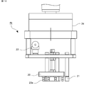
- FIG. 1 is a schematic configuration diagram of an assembly device according to the first embodiment.
- the assembling device 100 includes a robot 3, a robot hand 4 provided at the tip thereof, a control unit 5 for controlling the operation of the robot 3 and the robot hand 4, and the assembling device 100.
- the alignment members 7 and 8 are not particularly limited, but may be alignment pins.
- the control unit 5 may be mounted inside the robot 3, may exist outside the robot 3, and the robot 3 may be remotely controlled from the control unit 5 wirelessly or the like.
- the X and Y directions define the installation surface of the robot 3 or the plane of the stage 6 on which the first component 1 and the second component 2 are installed, and the Z direction is the XY plane. It defines the vertical direction perpendicular to. Further, in the following description, the positive direction of the Z-axis will be referred to as the upper side, and the negative direction will be referred to as the lower side.
- the first component 1 and the second component 2 are components that form a part of the housing of the electronic device, respectively.
- the material of the first component 1 and the second component 2 is not particularly limited, but it is preferably a resin molded product having appropriate elasticity for fitting by snap-fitting.
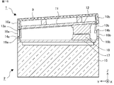
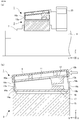
- FIG. 3 is a schematic cross-sectional view of the parts to be worked on by the assembly device according to the first embodiment before fitting.
- FIG. 4A is a schematic side view of the parts to be worked on by the assembly device according to the first embodiment before fitting
- FIG. 4B is a perspective view of the first part 1.
- the X direction is the depth direction of the first component 1 and the second component 2
- the Y direction is the width direction of the first component 1 and the second component 2
- the Z direction is the first component 1 and the first component 2.
- the two parts 2 coincide with each other in the height direction.
- the first board 11 is provided with the first connector 12.
- the first connector 12 is provided closer to the other than one of the pair of first side wall portions 10 facing each other in the width direction.
- the side far from the first connector 12 is referred to as the first side wall portion 10a
- the side closer to the first connector 12 is referred to as the first side wall portion 10b.
- the first side wall portion 10 it is described as the first side wall portion 10.
- the first side wall portion is shown as 10a, 10, or 10b, 10 in the drawings.
- the parts where similar members are described are expressed in the same manner.
- Two leg portions 13 are provided so as to extend in the height direction on each of the pair of first side wall portions 10 facing the width direction of the first component 1.
- the legs 13 extend to a height comparable to, for example, the opposite surface of the surface fixed to the first substrate 11 of the first connector 12.
- the legs 13 are formed with convex portions 14 projecting outward from the pair of first side wall portions 10.
- the convex portion 14 is provided at, for example, the lower end of the leg portion 13.
- the convex portion 14 preferably has a tapered shape narrowed in the protruding direction.
- the leg portion 13 and the convex portion 14 are described by omitting the hatching indicating the cross section from the viewpoint of easy viewing. The same applies to other drawings.
- the side far from the first connector 12 will be referred to as the leg 13a
- the side closer to the first connector 12 will be referred to as the leg 13b
- the leg 13 will be described.
- the convex portion 14a the side far from the first connector 12
- the convex portion 14b the side closer to the first connector 12
- the convex portion 14 is described.
- the second component 2 has a rectangular parallelepiped main body portion 15 and a second side wall portion 16 that is upright from the outer periphery of the upper surface of the main body portion 15 in the height direction.
- a second substrate 17 is fixedly provided inside the second component 2 surrounded by the second side wall portion 16.
- a second connector 18 is provided on the second substrate 17.
- the second connector 18 is provided closer to the other than one of the pair of second side wall portions 16 facing each other in the width direction.
- the second connector 18 is provided corresponding to the position of the first connector 12 of the first component 1.
- the first connector 12 and the second connector 18 are fitted, and the first component 1 and the second component 2 are electrically connected.
- the pair of second side wall portions 16 facing each other in the width direction of the second component 2 are formed with recesses 19 corresponding to the positions where the legs 13 of the first component 1 are provided.
- the recess 19 is, for example, a through hole penetrating the second side wall portion 16.
- the length from the upper surface of the second side wall portion 16 to the recess 19 is preferably the same as the length of the leg portion 13 in the height direction.
- the convex portion 14 formed on the leg portion 13 of the first component 1 is inserted into the concave portion 19 formed on the second side wall portion 16 of the second component 2 to be fitted by snap-fitting.
- the second side wall portion 16 is described by omitting the hatching showing the cross section from the viewpoint of easy viewing. The same applies to other drawings.
- the side far from the second connector 18 is referred to as the second side wall portion 16a
- the side closer to the second connector 18 is referred to as the second side wall portion 16b. In this case, it is described as the second side wall portion 16.
- the side far from the second connector 18 is described as the recess 19a
- the side closer to the second connector 18 is described as the recess 19b
- the recess 19 is described.
- the positions of the first connector 12 and the second connector 18, the legs 13 and the protrusions are formed.
- the positions of the portion 14 and the recess 19 are configured to coincide with each other in the width direction and the depth direction.
- FIG. 5 is a schematic cross-sectional view of the parts to be worked on by the assembly device according to the first embodiment after fitting.
- the leg portion 13 of the first component 1 is passed through the inside of the second side wall portion 16 of the second component 2.
- the convex portion 14 of the first component 1 is inserted into the concave portion 19 of the second component 2.
- the lower surface of the first side wall portion 10 of the first component 1 and the upper surface of the second side wall portion 16 are in contact with each other.
- the first component 1 When the first component 1 and the second component 2 are fitted together, the first component 1 is placed in the second component 1 while the first substrate 11 of the first component 1 remains parallel to the second substrate 17 of the second component 2.
- the first connector 12 and the second connector 18 interfere with each other before the convex portion 14 of the leg portion 13 is inserted into the concave portion 19, so that the fitting by snap fit cannot be performed. ..
- the first component 1 of the first component 1 is pushed in while the first substrate 11 of the first component 1 is parallel to the second substrate 17 of the second component 2, the first component 1 in the width direction and the depth direction is tried to be pushed. And the second component 2 may be out of alignment with each other.
- the first side wall portion 10a on the side far from the first connector 12 approaches the second side wall portion 16a on the side far from the second connector 18. It is necessary to tilt the first component 1 as described above. Then, the convex portion 14a of the leg portion 13a on the side far from the first connector 12 is inserted into the concave portion 19a of the second component 2. After that, the first connector 12 and the second connector 18 are fitted while returning the inclination of the first component 1 so that the first board 11 is parallel to the second board 17, and from the first connector 12. The convex portion 14b of the leg portion 13b on the near side is inserted into the concave portion 19b of the second component 2.
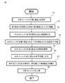
- FIG. 6 is a flowchart illustrating an assembling method using the assembling device according to the first embodiment.
- the first component 1 and the second component 2 are installed, for example, on the stage 6, and are installed at predetermined positions by the alignment members 7 and 8.
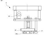
- FIG. 7 is a schematic configuration diagram of a robot hand of the assembly device according to the first embodiment.
- the robot hand 4 includes, for example, a grip portion 20 that grips the first component 1 and a pressing portion 21 that presses the top surface portion 9 of the first component 1.
- the grip portion 20 includes, for example, a suction pad 20a and is connected to the vacuum ejector 22.
- the vacuum ejector 22 performs a suction operation to create a vacuum state between the suction pad 20a and the vacuum ejector 22 and grip the first component 1. It becomes possible to do.
- the vacuum ejector 22 may further include a vacuum confirmation sensor capable of confirming the vacuum pressure.
- the material of the pressing portion 21 is not particularly limited, but is preferably a resin-based material so as not to damage the first component 1.
- the control unit 5 outputs a command to the robot hand 4 to grip the first component 1 (step S1).
- the robot hand 4 moves above the first component 1 in response to a command from the control unit 5.
- the vacuum ejector 22 starts the suction operation.
- the robot hand 4 descends to the position coordinates commanded by the control unit 5.
- the suction pad 20a of the robot hand 4 is in contact with the top surface portion 9 of the first component 1 at the position where the lowering of the robot hand 4 is completed.
- a vacuum is created between the suction pad 20a and the vacuum ejector 22, and the first component 1 is gripped.
- the vacuum state is confirmed by the vacuum confirmation sensor of the vacuum ejector 22.
- a signal is output from the vacuum confirmation sensor to the control unit 5.
- the control unit 5 Upon receiving the output signal, the control unit 5 outputs a command to the robot hand 4 to move the first component 1 to the upper side where the first component 1 is installed while holding the first component 1.
- control unit 5 outputs a command to the robot hand 4 to move the robot hand 4 to the upper side of the second component 2 while holding the first component 1 (step S2).
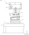
- FIG. 8 is a schematic configuration diagram for explaining the angle of the work object gripped by the robot hand of the assembly device according to the first embodiment.
- the angles commanded by the control unit 5 to the robot hand 4 in step S3 are, for example, the lower surface of the first side wall portion 10a on the side far from the first connector 12 of the first component 1 and the second connector 18 of the second component 2.
- the upper surface of the second side wall portion 16a on the distant side is in contact with the lower surface of the leg portion 13b on the side close to the first connector 12 of the first component 1, and the lower surface of the leg portion 13b on the side closer to the second connector 18 of the second component 2.
- the angle ⁇ 1 formed by the first substrate 11 and the second substrate 17 is set in a state where the upper surface of the two side wall portions 16b is in contact with each other.
- the control unit 5 outputs a command to lower the robot hand 4 from above the second component 2 in a state where the robot hand 4 and the first component 1 gripped by the robot hand 4 are tilted at an angle ⁇ 1 (step S4).
- the leg portion 13a on the side closer to the first connector 12 of the first component 1 is elastically deformed, and the second side wall portion 16a on the side farther from the second connector 18 of the second component 2 is formed. It is passed along the inner surface of the.
- the lower surface of the first side wall portion 10a on the side far from the first connector 12 of the first component 1 and the upper surface of the second side wall portion 16a on the side far from the second connector 18 of the second component 2 come into contact with each other.
- the lower surface of the leg portion 13b on the side close to the first connector 12 of the first component 1 and the upper surface of the second side wall portion 16b close to the second connector 18 of the second component 2 are brought into contact with each other.
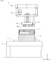
- FIG. 9 is a schematic configuration diagram showing the angles of the work target parts of the assembly device according to the first embodiment.
- the angle formed by the first substrate 11 and the second substrate 17 is smaller at the angle ⁇ 2 after the grip is released than at the angle ⁇ 1 before the grip is released. That is, the relationship is ⁇ 2 ⁇ 1.
- the convex portion 14a formed on the leg portion 13a extending from the first side wall portion 10a on the side far from the first connector 12 becomes the second side wall portion 16a on the side far from the second connector 18. It is inserted into the recess 19a.
- the first component 1 and the second component 2 are positioned in the width direction and the depth direction. As a result, misalignment can be prevented in the assembly steps after step S6 below.
- FIG. 10 is a schematic configuration diagram showing a part of an assembling process using the assembling device according to the first embodiment.
- the control unit 5 issues a command to the robot hand 4 to operate the robot hand 4 so as to take a horizontal state above the second component 2 (step S6).
- FIG. 11 is a schematic configuration diagram showing a part of the assembling process using the assembling device according to the first embodiment.
- the robot hand 4 is lowered again by the command of the control unit 5, and the pressing unit 21 presses the top surface portion 9 of the first component 1 (step S7).
- the first component 1 is pressed by the pressing portion 21 of the robot hand 4 and pressed against the second component 2.
- the contact point between the lower surface of the first side wall portion 10a of the first component 1 and the upper surface of the second side wall portion 16a of the second component 2 is the turning center, and the angle formed by the first substrate 11 and the second substrate 17 is formed. Becomes smaller.
- the leg portion 13b on the side close to the first connector 12 of the first component 1 elastically deforms and bends, while the second component 2 It is passed along the inner side surface of the second side wall portion 16b on the side close to the second connector 18 of the above. Then, the convex portion 14b of the leg portion 13b of the first component 1 is inserted into the concave portion 19b of the second side wall portion 16b of the second component 2, the leg portion 13b elastically returns to the original shape, and the fitting by snap fit is completed. do.
- the top surface portion 9 of the first component 1 is pressed by the pressing portion 21 of the robot hand 4, and the leg portion 13b of the first component 1 is passed along the inner surface of the second side wall portion 16b of the second component 2.
- the first connector 12 of the first component 1 and the second connector 18 of the second component 2 are fitted.
- the first connector 12 and the second connector 18 come into contact with each other to the other end as one end in the width direction comes into contact first and the first substrate 11 of the first component 1 becomes parallel to the second substrate 17 of the second component 2. Then, the fitting is completed (see FIG. 5).
- FIG. 12 is a schematic configuration diagram showing a part of the assembling process using the assembling device according to the first embodiment.
- the control unit 5 lowers the robot hand 4 to a predetermined position, determines that the fitting by the snap fit is completed, and moves the robot hand 4 to the upper side of the first component 1. (Step S8). As a result, the assembly of the first component 1 and the second component 2 is completed.
- step S5 as shown in FIG. 13, when the grip of the first component 1 is released, the leg portion 13a of the first component 1 is separated from the second side wall portion 16a of the second component 2. It is also possible that fitting by snap fit is not possible.
- FIG. 14 is configured so that such a situation does not occur.
- FIG. 14 is a schematic configuration diagram showing another example of the robot hand of the assembly device according to the first embodiment.
- the robot hand 4 preferably includes a first side wall guide 23 that comes into contact with the outer surface of the first side wall portion 10b on the side closer to the first connector 12 of the first component 1.
- the first side wall guide 23 can prevent the leg portion 13a and the convex portion 14a of the first component 1 from being separated from the second side wall portion 16a of the second component 2.
- FIG. 15 is a schematic configuration diagram showing a part of an assembling process using the assembling device according to the first embodiment.
- the convex portion 14b of the leg portion 13b on the side closer to the first connector 12 of the first component 1 is the second side wall portion 16b on the side closer to the second connector 18 of the second component 2.
- a part of the first connector 12 of the first component 1 and a part of the second connector 18 of the second component 2 come into contact with each other.
- the leg portion 13b of the first component 1 undergoes elastic deformation and elastic recovery from the time when a part of the first connector 12 and the second connector 18 comes into contact with each other until the fitting is completed, the first connector 12 and the second connector 12 and the second connector 18 are elastically restored.
- the position relative to the connector 18 may be displaced.
- FIG. 16 is a schematic configuration diagram showing parts that are work targets of the assembly device according to the first embodiment.
- the second connector 18 of the second component 2 has a surface portion 18a which is a surface on the side where the first connector 12 is fitted and a fixing portion 18b fixed to the second substrate 17. Be prepared.
- the external dimensions of the first connector 12 and the second connector 18 are determined in advance. Further, the position of the first connector on the first substrate 11 and the position of the second connector 18 on the second substrate 17 are determined. Further, the dimensions of the first side wall portion 10 of the first component 1, the dimensions of the leg portion 13, and the dimensions of the second side wall portion 16 of the second component 2 are determined.
- FIG. 17 is a schematic diagram for explaining a method of manufacturing an electronic device in which parts are assembled using the assembling device according to the first embodiment.
- the X-axis is the depth direction of the second component 2
- the Y-axis is the width direction of the second component 2
- the Z-axis is the height direction of the second component 2.
- the second component 2 requires a floating amount in the Y-axis direction.
- the first connector 12 and the second connector 18 each have a rectangular parallelepiped shape. Further, it is assumed that the first substrate 11 to which the first connector 12 is fixed and the lower surface of the first side wall portion 10a are in the same plane.
- FIG. 17 the first component first side wall 10a of the lower surface and the pressing portion 21 from a state in which the upper surface and is in contact at the contact point P 1 of the robot hand 4 of the second part 2 of the second side wall portion 16a of one first A state in which the top surface portion 9 of the component 1 is pressed is shown.
- the lower surface and the first component first contact point P 1 becomes the center of the upper surface of the second side wall portion 16a of the first side wall portion 10a is rotated ..
- the first first connector 12 of the component 1 and the second connector 18 of the second part 2 is in contact at the contact point P 2.
- the linear distance from the contact point P 1 between the lower surface and the upper surface of the second side wall portion 16a of the first side wall 10a to the contact point P 2 between the first connector 12 and second connector 18 L Set to 0.
- the horizontal distance from the contact point P 1 between the lower surface and the upper surface of the second side wall portion 16a of the first side wall 10a to the side surface of the first side wall portion 10a of the second connector 18 and L 1.
- the linear distance from the contact point P 1 between the lower surface and the upper surface of the second side wall portion 16a of the first side wall 10a to the side surface of the first side wall portion 10a side of the first connector 12 and L 2.
- the positions of the first connector 12 on the first substrate 11, the positions of the second connector 18 on the second substrate 17, and the external dimensions of the first connector 12 and the second connector 18 are predetermined. That is, L 1 , L 2 , T 1 , and T 2 are known.
- L 3 The floating amount required for the second connector 18 of the second component 2 is calculated by L 3 ⁇ L 1.
- L 3 can be obtained by substituting Eqs. (2) and (3) into Eq. (1).
- L 3 can be calculated from the formula (1) to the formula (3), and the floating amount of the second connector 18 of the second component 2 is calculated by L 3 ⁇ L 1.
- a floating mechanism considering the calculated floating amount is formed between the surface portion 18a and the fixing portion 18b of the second connector 18 of the second component 2.
- the assembling device 100 includes a robot 3, a robot hand 4, and a control unit 5 for controlling them.
- the control unit 5 grips the first component 1 with the gripping unit 20 of the robot hand 4.
- the robot hand 4 is tilted so that one of the pair of first side wall portions 10 of the first component 1 is located below the other.
- the tilted robot hand 4 is lowered until one of the pair of first side wall portions 10 comes into contact with one of the second side wall portions 16 to release the grip of the first component 1, so that the pair of first side wall portions 10 is released.
- the leg portion 13 extending downward from one side is passed through the inside of the pair of second side wall portions 16, and the convex portion 14a protruding outward from the pair of first side wall portions 10 from the leg portion 13a is passed through the pair of second side wall portions. It is inserted into the recess 19a formed on one side of 16. Then, by pressing the first component 1 with the pressing portion 21 of the robot hand 4 so that the first substrate 11 and the second substrate 17 are parallel to each other, the first component 1 extends downward from the other of the pair of first side wall portions 10.
- the leg portion 13a is passed through the inside of the pair of second side wall portions 16, and the convex portion 14b protruding outward from the pair of first side wall portions 10 from the leg portion 13 is formed on the other side of the pair of second side wall portions 16. It is inserted into the recess 19b.
- fitting by a connector and fitting by a snap fit become possible.
- the convex portion 14a formed on the leg portion 13a is inserted into the concave portion 19a formed on one of the pair of second side wall portions 16 and then the first component 1 is pressed by the pressing portion 21, the first component 1 is pressed. It is possible to prevent the relative positions of the 1st component 1 and the 2nd component 2 from shifting.
- one lower surface of a pair of first side wall portions 10 and a pair of first side wall portions 10 are assembled.
- the first connector 12 and the second connector 18 from the horizontal distance from the contact point with the upper surface of one of the two side wall portions 16 to the second connector 18 and the contact point with the upper surface of one of the pair of second side wall portions 16.
- a floating mechanism is formed in the second connector 18 based on the difference from the horizontal distance to the contact point of.
- the assembling device according to the present embodiment further includes a load sensor 24 for detecting the load due to the reaction force from the first component 1 on the robot hand 4b, and the robot hand 4b responds to the load detected by the load sensor 24. Control the descending motion.
- FIG. 18 is a schematic configuration diagram showing a robot hand of the assembly device according to the second embodiment.
- the robot hand 4b includes a load sensor 24 that detects a reaction force.
- the load sensor 24 is, for example, a contact type sensor, in which the pressing portion 21 of the robot hand 4b presses the top surface portion 9 of the first component 1 and the convex portion 14 of the first component 1 fits into the concave portion 19 of the second component 2. It detects the reaction force when it is pushed in.
- FIG. 19 is a flowchart illustrating the assembling method of the present embodiment. The part that overlaps with the description shown in the first embodiment will be omitted as appropriate.
- the control unit 5 outputs a command to the robot hand 4b to grip the first component 1 (FIG. 19, step S1).
- the robot hand 4b moves to the upper part of the first component 1 in response to a command from the control unit 5, and causes the vacuum ejector 22 to start the suction operation.
- the robot hand 4b descends to a predetermined position coordinate in response to a command from the control unit 5.
- the first component 1 is gripped by the suction pad 20a of the grip portion 20 of the robot hand 4b.
- the robot hand 4b moves to the upper part of the second component 2 in response to a command from the control unit 5 (step S2).
- the control unit 5 of the pair of first side wall portions 10 facing each other in the width direction of the first component 1, the lower surface of the first side wall portion 10a on the side farther from the first connector 12 is on the side closer to the first connector 12.
- the robot hand 4b is tilted so as to be located below the lower surface of the first side wall portion 10b. (Step S3).
- the first component 1 is also tilted at the same angle.
- the lower surface of the first side wall portion 10a of the first component 1 and the upper surface of the second side wall portion 16a of the second component 2 are in contact with each other, and the lower surface of the leg portion 13b of the first component 1 and the second component are in contact with each other.
- the lowering operation is performed to a position where the upper surface of the second side wall portion 16b of No. 2 comes into contact with the upper surface (step S4).
- the vacuum ejector 22 of the robot hand 4b stops the suction operation and performs the vacuum breaking operation.
- the suction pad 20a is separated from the top surface portion 9 of the first component 1 to release the grip (step S5).
- the convex portion 14a formed on the leg portion 13a extending from the first side wall portion 10a on the side far from the first connector 12 becomes the second side wall portion 16a on the side far from the second connector 18. It is inserted into the recess 19a.
- the robot hand 4b is returned to a horizontal state above the first component 1 (step S6).
- the robot hand 4b performs a descending operation again (step S7).
- the pressing portion 21 of the robot hand 4b presses the top surface portion 9 of the first component 1 and presses the first component 1 toward the second component 2 (step S7).
- the leg portion 13b of the first component 1 elastically deforms and bends, and inside the second side wall portion 16b of the second component 2. Passed through.
- the load sensor 24 detects the reaction force when the pressing portion 21 of the robot hand 4b presses the first component 1.
- the load sensor 24 has a load at the time of primary insertion due to bending of the leg portion 13b when the leg portion 13b of the first component 1 starts to be passed through the second side wall portion 16b of the second component 2, and when the fitting is completed. Detects the final pushing load of.
- the load at the time of primary insertion bends the leg portion 13b, so that a large load is required. Therefore, the load relationship is that the load at the time of primary insertion> the final pushing load.
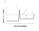
- FIG. 20 is a relationship diagram showing the relationship between the load of the load sensor of the assembly device according to the second embodiment and the position coordinates in the descending direction.
- the vertical axis shows the load of the load sensor
- the horizontal axis shows the position coordinates in the descending direction.
- the load detected by the load sensor 24 is the load F1 when the leg portion 13b of the first component 1 enters the inside of the second side wall portion 16b of the second component 2 and begins to bend.
- the load F2 when the leg portion 13b of the first component 1 is pushed in in a bent state
- the load F3 when the convex portion 14b of the leg portion 13b of the first component 1 is fitted into the concave portion 19b of the second component 2. It is displaced in three stages.
- the load F3 of the load sensor 24 increases.
- the load sensor 24 detects that the detected load is within the range S of the load at the time of fitting completed, which is stored in advance, at the position coordinates where the fitting is completed, and determines the fitting completion (step S9). .. If the load does not fall within the range of the load stored in advance, it may be determined that the fitting is defective and an abnormality may be transmitted to the control unit and the outside (step S10).
- the control unit 5 raises the robot hand 4b after the load at the time of fitting completion is within the range of the load stored in advance, and after it is determined that the fitting is completed, the first component 1 and the second component 2 are fitted. Is completed (step S8).
- the robot hand 4b holding the first component 1 is held by one of the pair of first side wall portions 10 of the first component 1. Tilt so that it is located below, and in the tilted state, lower the first component 1 from above the second component 2, release the grip of the robot hand 4b, and then attach the first component 1 to the second component 2. Press. This enables fitting by a connector and fitting by a snap fit.
- the lowering motion of the robot hand 4b can be controlled according to the load detected by the load sensor 24, and the load on the first component 1 and the second component 2 is reduced. Further, by detecting the load of the reaction force pushed by the load sensor 24, when a load outside the permissible range is detected in the load pushed at the time of primary insertion and the final insertion, the first component 1 and the second component 2 It is possible to determine a fitting defect.
- the floating mechanism described in the first embodiment can also be mounted in the second embodiment.
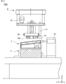
- the assembling device 100b according to the present embodiment further includes a second side wall guide 25 which is a mechanism for pressing the first side wall portion 10 of the first component 1 on the stage 6, and the first component 1 is provided with the first side wall guide 25. Assembling is performed by pressing from two directions of the Z axis and the Y axis.
- the first component When the dimension 16c between the second side wall portions 16 of the second component 2 is smaller than the dimension 13c between the legs 13 of 1, the pressing portion 21 of the robot hand 4 presses the top surface portion 9 of the first component 1.
- the leg portion 13b of the first component 1 comes into contact with the upper portion of the second side wall portion 16b of the second component 2, and the leg portion 13b of the first component 1 does not elastically deform, making assembly impossible.
- assembling is possible by performing not only the pressing in the Z-axis direction described in the first and second embodiments but also the pressing in the Y-axis direction.
- FIG. 22 is a schematic configuration diagram of the assembly device according to the third embodiment.
- the stage 6 includes a second side wall guide 25 which is a pressing mechanism for pressing the first side wall portion 10 of the first component 1.
- the second side wall guide 25 is, for example, a pneumatic cylinder, and presses the first side wall portion 10 in the Y-axis direction before the pressing portion 21 of the robot hand 4 presses the top surface portion 9 of the first component 1. It is a thing.
- FIG. 23 is a flowchart illustrating the assembling method of the present embodiment. The part that overlaps with the description shown in the first embodiment will be omitted as appropriate.
- the control unit 5 outputs a command to the robot hand 4b to grip the first component 1 (FIG. 6, step S1).
- the robot hand 4b moves to the upper part of the first component 1 in response to a command from the control unit 5, and causes the vacuum ejector 22 to start the suction operation.
- the robot hand 4b descends to a predetermined position coordinate in response to a command from the control unit 5.
- the first component 1 is gripped by the suction pad 20a of the grip portion 20 of the robot hand 4b.
- the robot hand 4b moves to the upper part of the second component 2 in response to a command from the control unit 5 (step S2).
- the control unit 5 of the pair of first side wall portions 10 facing each other in the width direction of the first component 1, the lower surface of the first side wall portion 10a on the side farther from the first connector 12 is on the side closer to the first connector 12.
- the robot hand 4b is tilted so as to be located below the lower surface of the first side wall portion 10b. (Step S3).
- the first component 1 is also tilted at the same angle.
- the lower surface of the first side wall portion 10a of the first component 1 and the upper surface of the second side wall portion 16a of the second component 2 are in contact with each other, and the lower surface of the leg portion 13b of the first component 1 and the second component are in contact with each other.
- the lowering operation is performed to a position where the upper surface of the second side wall portion 16b of No. 2 comes into contact with the upper surface (step S4).
- the vacuum ejector 22 of the robot hand 4b stops the suction operation and performs the vacuum breaking operation.
- the suction pad 20a is separated from the top surface portion 9 of the first component 1 to release the grip (step S5).
- the convex portion 14a formed on the leg portion 13a extending from the first side wall portion 10a on the side far from the first connector 12 becomes the concave portion of the second side wall portion 16a on the side far from the second connector 18. It is inserted in 19a.
- the robot hand 4b is returned to a horizontal state above the first component 1 (step S6).
- the first side wall portion 10b of the first component 1 is pressed in the Y-axis direction by the second side wall guide 25 that presses the first side wall portion 10 provided in the stage 6. (Step S11).
- the leg portion 13a of the first component 1 elastically deforms and bends as shown in FIG. 24 (b), and the second component 2 second. 2 It is pressed inside the side wall portion 16a.
- the first side wall portion 10b of the first component 1 is first pressed in the Y-axis direction, the leg portion 13a of the first component 1 is bent, and the pressing portion 21 of the robot hand 4 is pressed.
- the leg portion 13b of the first component 1 becomes the second side wall portion 16b of the second component 2. It becomes easier to enter.
- the robot hand 4 performs the lowering operation again while pressing the first side wall portion 10b of the first component 1. Then, the pressing portion 21 of the robot hand 4 presses the top surface portion 9 of the first component 1 and presses the first component 1 toward the second component 2 (step S7).
- the robot hand 4b holding the first component 1 is attached to the pair of first side wall portions of the first component 1. Tilt so that one side of 10 is located below the other, and in the tilted state, lower the first part 1 from above the second part 2, release the grip of the robot hand 4b, and then move the first part 1 to the first part. 2 Press against the part 2. This enables fitting by a connector and fitting by a snap fit.
- the assembly can be performed without difficulty. Make it possible.
- the floating mechanism described in the first embodiment can also be mounted in the third embodiment.
- the robot 3 is a 6-axis robot, but a robot having less than 6 axes or a robot having 6 or more axes may be used.
- the robot 3 may be a three-axis orthogonal type robot having orthogonal movements of the X, Y-axis, and Z-axis, and may have a mechanism that allows the hand mounting portion to turn in one axis.
- a robot other than the vertical articulated type such as a horizontal articulated type may be used.
- the robot hands 4 and 4b are provided with the vacuum ejector 22 and the grip portion 20 has the suction pad 20a.
- the first component 1 can be gripped, for example, an air chuck. May be used.
- the robot hand may be provided with several fingers for sandwiching and gripping the first component 1.
- two leg portions 13a are provided on the first side wall portions 10 facing each other of the first component 1, and two legs are provided on the second side wall portions 16 facing each other of the second component 2.
- the leg portion 13 and the recess 19 may be two or more.
Landscapes
- Engineering & Computer Science (AREA)
- Mechanical Engineering (AREA)
- Robotics (AREA)
- Manufacturing & Machinery (AREA)
- Automatic Assembly (AREA)
- Manipulator (AREA)
- Manufacturing Of Electrical Connectors (AREA)
- Coupling Device And Connection With Printed Circuit (AREA)
- Supply And Installment Of Electrical Components (AREA)
Priority Applications (2)
| Application Number | Priority Date | Filing Date | Title |
|---|---|---|---|
| CN202080099550.7A CN115443587B (zh) | 2020-04-14 | 2020-10-20 | 组装装置、组装方法及电子设备的制造方法 |
| JP2022515194A JP7224537B2 (ja) | 2020-04-14 | 2020-10-20 | 組付装置、組付方法および電子機器の製造方法 |
Applications Claiming Priority (2)
| Application Number | Priority Date | Filing Date | Title |
|---|---|---|---|
| JP2020072102 | 2020-04-14 | ||
| JP2020-072102 | 2020-04-14 |
Publications (1)
| Publication Number | Publication Date |
|---|---|
| WO2021210200A1 true WO2021210200A1 (ja) | 2021-10-21 |
Family
ID=78084097
Family Applications (1)
| Application Number | Title | Priority Date | Filing Date |
|---|---|---|---|
| PCT/JP2020/039316 Ceased WO2021210200A1 (ja) | 2020-04-14 | 2020-10-20 | 組付装置、組付方法および電子機器の製造方法 |
Country Status (3)
| Country | Link |
|---|---|
| JP (1) | JP7224537B2 (https=) |
| CN (1) | CN115443587B (https=) |
| WO (1) | WO2021210200A1 (https=) |
Cited By (1)
| Publication number | Priority date | Publication date | Assignee | Title |
|---|---|---|---|---|
| JP2024118123A (ja) * | 2023-02-20 | 2024-08-30 | 日立グローバルライフソリューションズ株式会社 | 引出扉自動組付装置および引出扉自動組付方法 |
Citations (7)
| Publication number | Priority date | Publication date | Assignee | Title |
|---|---|---|---|---|
| JPH0488688U (https=) * | 1990-12-11 | 1992-07-31 | ||
| JPH0946059A (ja) * | 1995-07-28 | 1997-02-14 | Yazaki Corp | カバー付電気接続箱 |
| JP2014037030A (ja) * | 2012-08-17 | 2014-02-27 | Fujitsu Ltd | パーツの組付装置及びパーツの組付方法 |
| JP2015104207A (ja) * | 2013-11-25 | 2015-06-04 | 矢崎総業株式会社 | 電気接続箱 |
| JP2017030090A (ja) * | 2015-07-31 | 2017-02-09 | 富士通株式会社 | ロボットハンド、情報処理装置製造装置、情報処理装置製造方法 |
| JP2018114585A (ja) * | 2017-01-18 | 2018-07-26 | 富士通株式会社 | 組立装置及び組立方法 |
| JP2018143013A (ja) * | 2017-02-27 | 2018-09-13 | 日立オートモティブシステムズ株式会社 | 電子制御装置 |
Family Cites Families (5)
| Publication number | Priority date | Publication date | Assignee | Title |
|---|---|---|---|---|
| SU1618650A1 (ru) * | 1988-08-16 | 1991-01-07 | Всесоюзный Проектно-Конструкторский Институт Технологии Электротехнического Производства | Схват сборочного манипул тора |
| JP6184169B2 (ja) * | 2013-05-21 | 2017-08-23 | 福田 敏男 | 組立て装置、部品の組立て方法及び相対位置調整方法 |
| CN107414452B (zh) * | 2017-08-08 | 2020-04-10 | 珠海格力智能装备有限公司 | 电池盖装配装置及装配方法 |
| JP7122857B2 (ja) * | 2018-05-07 | 2022-08-22 | 三菱電機株式会社 | 部品組み付け装置及び部品組み付け方法 |
| CN208662993U (zh) * | 2018-07-06 | 2019-03-29 | 苏州富强科技有限公司 | 一种摆片组件自动装配设备中的上治具 |
-
2020
- 2020-10-20 WO PCT/JP2020/039316 patent/WO2021210200A1/ja not_active Ceased
- 2020-10-20 JP JP2022515194A patent/JP7224537B2/ja active Active
- 2020-10-20 CN CN202080099550.7A patent/CN115443587B/zh active Active
Patent Citations (7)
| Publication number | Priority date | Publication date | Assignee | Title |
|---|---|---|---|---|
| JPH0488688U (https=) * | 1990-12-11 | 1992-07-31 | ||
| JPH0946059A (ja) * | 1995-07-28 | 1997-02-14 | Yazaki Corp | カバー付電気接続箱 |
| JP2014037030A (ja) * | 2012-08-17 | 2014-02-27 | Fujitsu Ltd | パーツの組付装置及びパーツの組付方法 |
| JP2015104207A (ja) * | 2013-11-25 | 2015-06-04 | 矢崎総業株式会社 | 電気接続箱 |
| JP2017030090A (ja) * | 2015-07-31 | 2017-02-09 | 富士通株式会社 | ロボットハンド、情報処理装置製造装置、情報処理装置製造方法 |
| JP2018114585A (ja) * | 2017-01-18 | 2018-07-26 | 富士通株式会社 | 組立装置及び組立方法 |
| JP2018143013A (ja) * | 2017-02-27 | 2018-09-13 | 日立オートモティブシステムズ株式会社 | 電子制御装置 |
Cited By (2)
| Publication number | Priority date | Publication date | Assignee | Title |
|---|---|---|---|---|
| JP2024118123A (ja) * | 2023-02-20 | 2024-08-30 | 日立グローバルライフソリューションズ株式会社 | 引出扉自動組付装置および引出扉自動組付方法 |
| JP7836779B2 (ja) | 2023-02-20 | 2026-03-27 | 日立グローバルライフソリューションズ株式会社 | 引出扉自動組付装置および引出扉自動組付方法 |
Also Published As
| Publication number | Publication date |
|---|---|
| CN115443587A (zh) | 2022-12-06 |
| JP7224537B2 (ja) | 2023-02-17 |
| JPWO2021210200A1 (https=) | 2021-10-21 |
| CN115443587B (zh) | 2025-11-14 |
Similar Documents
| Publication | Publication Date | Title |
|---|---|---|
| CN107336229B (zh) | 机器人以及机器人系统 | |
| US10363661B2 (en) | Control device, robot, and robot system | |
| US20190381669A1 (en) | Robot apparatus, control method for robot apparatus, article manufacturing method using robot apparatus, and storage medium | |
| JP6841206B2 (ja) | ロボットシステム及びロボットの制御方法 | |
| CN109278063B (zh) | 机器人装置、控制方法、组装方法和记录介质 | |
| JP6996113B2 (ja) | ロボット制御方法、ロボットシステムおよび制御装置 | |
| JP6693098B2 (ja) | ロボット、及びロボットシステム | |
| US20180243907A1 (en) | Attachment apparatus, attachment method, and hand mechanism | |
| JPH07241733A (ja) | 部品自動組立方法及び部品自動組立装置 | |
| JP6988757B2 (ja) | エンドエフェクタおよびエンドエフェクタ装置 | |
| Hartisch et al. | Compliant finray-effect gripper for high-speed robotic assembly of electrical components | |
| CN108858182B (zh) | 机器人的控制装置及控制方法以及机器人系统 | |
| JPWO2018043212A1 (ja) | 組立装置、及び電子機器の製造方法 | |
| JP7147419B2 (ja) | エンドエフェクタ装置 | |
| JP2021122923A (ja) | 制御方法、ロボット装置、ロボットシステム、および物品の製造方法 | |
| WO2021210200A1 (ja) | 組付装置、組付方法および電子機器の製造方法 | |
| CN114952915A (zh) | 机械手、机械手组件、机器人及装配带线束的插头的方法 | |
| CN114746226B (zh) | 连接器嵌合装置及连接器嵌合方法 | |
| TWI788263B (zh) | 電子設備組裝裝置和電子設備組裝方法(三) | |
| CN112975947A (zh) | 元器件引脚的矫正方法、装置、设备及存储介质 | |
| US20200189109A1 (en) | Robot arm apparatus, component fastening system including same, and component fastening method using robot arm apparatus | |
| JP7692417B2 (ja) | 動作方法、ロボットシステム、制御装置、教示方法及びプログラム | |
| JP7361626B2 (ja) | 組立装置及び電子機器の製造方法 | |
| KR102866428B1 (ko) | 커넥터 조립을 위한 정렬장치 및 정렬장치에 의하여 수행되는 정렬방법 | |
| WO2022244437A1 (ja) | ロボットコントローラ、制御方法および制御プログラム |
Legal Events
| Date | Code | Title | Description |
|---|---|---|---|
| 121 | Ep: the epo has been informed by wipo that ep was designated in this application |
Ref document number: 20931119 Country of ref document: EP Kind code of ref document: A1 |
|
| ENP | Entry into the national phase |
Ref document number: 2022515194 Country of ref document: JP Kind code of ref document: A |
|
| WWE | Wipo information: entry into national phase |
Ref document number: 202080099550.7 Country of ref document: CN |
|
| NENP | Non-entry into the national phase |
Ref country code: DE |
|
| 122 | Ep: pct application non-entry in european phase |
Ref document number: 20931119 Country of ref document: EP Kind code of ref document: A1 |