WO2021205710A1 - モータ制御装置、電動車両、およびモータ制御方法 - Google Patents
モータ制御装置、電動車両、およびモータ制御方法 Download PDFInfo
- Publication number
- WO2021205710A1 WO2021205710A1 PCT/JP2021/002146 JP2021002146W WO2021205710A1 WO 2021205710 A1 WO2021205710 A1 WO 2021205710A1 JP 2021002146 W JP2021002146 W JP 2021002146W WO 2021205710 A1 WO2021205710 A1 WO 2021205710A1
- Authority
- WO
- WIPO (PCT)
- Prior art keywords
- motor
- inverter circuit
- pulsation
- electromagnetic force
- carrier signal
- Prior art date
- Legal status (The legal status is an assumption and is not a legal conclusion. Google has not performed a legal analysis and makes no representation as to the accuracy of the status listed.)
- Ceased
Links
Images


Classifications
-
- H—ELECTRICITY
- H02—GENERATION; CONVERSION OR DISTRIBUTION OF ELECTRIC POWER
- H02M—APPARATUS FOR CONVERSION BETWEEN AC AND AC, BETWEEN AC AND DC, OR BETWEEN DC AND DC, AND FOR USE WITH MAINS OR SIMILAR POWER SUPPLY SYSTEMS; CONVERSION OF DC OR AC INPUT POWER INTO SURGE OUTPUT POWER; CONTROL OR REGULATION THEREOF
- H02M7/00—Conversion of AC power input into DC power output; Conversion of DC power input into AC power output
- H02M7/42—Conversion of DC power input into AC power output without possibility of reversal
- H02M7/44—Conversion of DC power input into AC power output without possibility of reversal by static converters
- H02M7/48—Conversion of DC power input into AC power output without possibility of reversal by static converters using discharge tubes with control electrode or semiconductor devices with control electrode
- H02M7/53—Conversion of DC power input into AC power output without possibility of reversal by static converters using discharge tubes with control electrode or semiconductor devices with control electrode using devices of a triode or transistor type requiring continuous application of a control signal
- H02M7/537—Conversion of DC power input into AC power output without possibility of reversal by static converters using discharge tubes with control electrode or semiconductor devices with control electrode using devices of a triode or transistor type requiring continuous application of a control signal using semiconductor devices only, e.g. single switched pulse inverters
- H02M7/5387—Conversion of DC power input into AC power output without possibility of reversal by static converters using discharge tubes with control electrode or semiconductor devices with control electrode using devices of a triode or transistor type requiring continuous application of a control signal using semiconductor devices only, e.g. single switched pulse inverters in a bridge configuration
- H02M7/53871—Conversion of DC power input into AC power output without possibility of reversal by static converters using discharge tubes with control electrode or semiconductor devices with control electrode using devices of a triode or transistor type requiring continuous application of a control signal using semiconductor devices only, e.g. single switched pulse inverters in a bridge configuration with automatic control of output voltage or current
-
- H—ELECTRICITY
- H02—GENERATION; CONVERSION OR DISTRIBUTION OF ELECTRIC POWER
- H02P—CONTROL OR REGULATION OF ELECTRIC MOTORS, ELECTRIC GENERATORS OR DYNAMO-ELECTRIC CONVERTERS; CONTROLLING TRANSFORMERS, REACTORS OR CHOKE COILS
- H02P27/00—Arrangements or methods for the control of AC motors characterised by the kind of supply voltage
- H02P27/04—Arrangements or methods for the control of AC motors characterised by the kind of supply voltage using variable-frequency supply voltage, e.g. inverter or converter supply voltage
- H02P27/06—Arrangements or methods for the control of AC motors characterised by the kind of supply voltage using variable-frequency supply voltage, e.g. inverter or converter supply voltage using DC to AC converters or inverters
- H02P27/08—Arrangements or methods for the control of AC motors characterised by the kind of supply voltage using variable-frequency supply voltage, e.g. inverter or converter supply voltage using DC to AC converters or inverters with pulse width modulation
-
- B—PERFORMING OPERATIONS; TRANSPORTING
- B60—VEHICLES IN GENERAL
- B60L—PROPULSION OF ELECTRICALLY-PROPELLED VEHICLES; SUPPLYING ELECTRIC POWER FOR AUXILIARY EQUIPMENT OF ELECTRICALLY-PROPELLED VEHICLES; ELECTRODYNAMIC BRAKE SYSTEMS FOR VEHICLES IN GENERAL; MAGNETIC SUSPENSION OR LEVITATION FOR VEHICLES; MONITORING OPERATING VARIABLES OF ELECTRICALLY-PROPELLED VEHICLES; ELECTRIC SAFETY DEVICES FOR ELECTRICALLY-PROPELLED VEHICLES
- B60L15/00—Methods, circuits, or devices for controlling the traction-motor speed of electrically-propelled vehicles
- B60L15/02—Methods, circuits, or devices for controlling the traction-motor speed of electrically-propelled vehicles characterised by the form of the current used in the control circuit
- B60L15/025—Methods, circuits, or devices for controlling the traction-motor speed of electrically-propelled vehicles characterised by the form of the current used in the control circuit using field orientation; Vector control; Direct Torque Control [DTC]
-
- B—PERFORMING OPERATIONS; TRANSPORTING
- B60—VEHICLES IN GENERAL
- B60L—PROPULSION OF ELECTRICALLY-PROPELLED VEHICLES; SUPPLYING ELECTRIC POWER FOR AUXILIARY EQUIPMENT OF ELECTRICALLY-PROPELLED VEHICLES; ELECTRODYNAMIC BRAKE SYSTEMS FOR VEHICLES IN GENERAL; MAGNETIC SUSPENSION OR LEVITATION FOR VEHICLES; MONITORING OPERATING VARIABLES OF ELECTRICALLY-PROPELLED VEHICLES; ELECTRIC SAFETY DEVICES FOR ELECTRICALLY-PROPELLED VEHICLES
- B60L3/00—Electric devices on electrically-propelled vehicles for safety purposes; Monitoring operating variables, e.g. speed, deceleration or energy consumption
- B60L3/0092—Electric devices on electrically-propelled vehicles for safety purposes; Monitoring operating variables, e.g. speed, deceleration or energy consumption with use of redundant elements for safety purposes
-
- B—PERFORMING OPERATIONS; TRANSPORTING
- B60—VEHICLES IN GENERAL
- B60L—PROPULSION OF ELECTRICALLY-PROPELLED VEHICLES; SUPPLYING ELECTRIC POWER FOR AUXILIARY EQUIPMENT OF ELECTRICALLY-PROPELLED VEHICLES; ELECTRODYNAMIC BRAKE SYSTEMS FOR VEHICLES IN GENERAL; MAGNETIC SUSPENSION OR LEVITATION FOR VEHICLES; MONITORING OPERATING VARIABLES OF ELECTRICALLY-PROPELLED VEHICLES; ELECTRIC SAFETY DEVICES FOR ELECTRICALLY-PROPELLED VEHICLES
- B60L50/00—Electric propulsion with power supplied within the vehicle
- B60L50/50—Electric propulsion with power supplied within the vehicle using propulsion power supplied by batteries or fuel cells
- B60L50/51—Electric propulsion with power supplied within the vehicle using propulsion power supplied by batteries or fuel cells characterised by AC-motors
-
- H—ELECTRICITY
- H02—GENERATION; CONVERSION OR DISTRIBUTION OF ELECTRIC POWER
- H02M—APPARATUS FOR CONVERSION BETWEEN AC AND AC, BETWEEN AC AND DC, OR BETWEEN DC AND DC, AND FOR USE WITH MAINS OR SIMILAR POWER SUPPLY SYSTEMS; CONVERSION OF DC OR AC INPUT POWER INTO SURGE OUTPUT POWER; CONTROL OR REGULATION THEREOF
- H02M7/00—Conversion of AC power input into DC power output; Conversion of DC power input into AC power output
- H02M7/42—Conversion of DC power input into AC power output without possibility of reversal
- H02M7/44—Conversion of DC power input into AC power output without possibility of reversal by static converters
- H02M7/48—Conversion of DC power input into AC power output without possibility of reversal by static converters using discharge tubes with control electrode or semiconductor devices with control electrode
- H02M7/493—Conversion of DC power input into AC power output without possibility of reversal by static converters using discharge tubes with control electrode or semiconductor devices with control electrode the static converters being arranged for operation in parallel
-
- H—ELECTRICITY
- H02—GENERATION; CONVERSION OR DISTRIBUTION OF ELECTRIC POWER
- H02M—APPARATUS FOR CONVERSION BETWEEN AC AND AC, BETWEEN AC AND DC, OR BETWEEN DC AND DC, AND FOR USE WITH MAINS OR SIMILAR POWER SUPPLY SYSTEMS; CONVERSION OF DC OR AC INPUT POWER INTO SURGE OUTPUT POWER; CONTROL OR REGULATION THEREOF
- H02M7/00—Conversion of AC power input into DC power output; Conversion of DC power input into AC power output
- H02M7/42—Conversion of DC power input into AC power output without possibility of reversal
- H02M7/44—Conversion of DC power input into AC power output without possibility of reversal by static converters
- H02M7/48—Conversion of DC power input into AC power output without possibility of reversal by static converters using discharge tubes with control electrode or semiconductor devices with control electrode
- H02M7/53—Conversion of DC power input into AC power output without possibility of reversal by static converters using discharge tubes with control electrode or semiconductor devices with control electrode using devices of a triode or transistor type requiring continuous application of a control signal
- H02M7/537—Conversion of DC power input into AC power output without possibility of reversal by static converters using discharge tubes with control electrode or semiconductor devices with control electrode using devices of a triode or transistor type requiring continuous application of a control signal using semiconductor devices only, e.g. single switched pulse inverters
- H02M7/539—Conversion of DC power input into AC power output without possibility of reversal by static converters using discharge tubes with control electrode or semiconductor devices with control electrode using devices of a triode or transistor type requiring continuous application of a control signal using semiconductor devices only, e.g. single switched pulse inverters with automatic control of output wave form or frequency
- H02M7/5395—Conversion of DC power input into AC power output without possibility of reversal by static converters using discharge tubes with control electrode or semiconductor devices with control electrode using devices of a triode or transistor type requiring continuous application of a control signal using semiconductor devices only, e.g. single switched pulse inverters with automatic control of output wave form or frequency by pulse-width modulation
-
- H—ELECTRICITY
- H02—GENERATION; CONVERSION OR DISTRIBUTION OF ELECTRIC POWER
- H02P—CONTROL OR REGULATION OF ELECTRIC MOTORS, ELECTRIC GENERATORS OR DYNAMO-ELECTRIC CONVERTERS; CONTROLLING TRANSFORMERS, REACTORS OR CHOKE COILS
- H02P25/00—Arrangements or methods for the control of AC motors characterised by the kind of AC motor or by structural details
- H02P25/16—Arrangements or methods for the control of AC motors characterised by the kind of AC motor or by structural details characterised by the circuit arrangement or by the kind of wiring
- H02P25/22—Multiple windings; Windings for more than three phases
-
- H—ELECTRICITY
- H02—GENERATION; CONVERSION OR DISTRIBUTION OF ELECTRIC POWER
- H02P—CONTROL OR REGULATION OF ELECTRIC MOTORS, ELECTRIC GENERATORS OR DYNAMO-ELECTRIC CONVERTERS; CONTROLLING TRANSFORMERS, REACTORS OR CHOKE COILS
- H02P29/00—Arrangements for regulating or controlling electric motors, appropriate for both AC and DC motors
- H02P29/50—Reduction of harmonics
-
- H—ELECTRICITY
- H02—GENERATION; CONVERSION OR DISTRIBUTION OF ELECTRIC POWER
- H02P—CONTROL OR REGULATION OF ELECTRIC MOTORS, ELECTRIC GENERATORS OR DYNAMO-ELECTRIC CONVERTERS; CONTROLLING TRANSFORMERS, REACTORS OR CHOKE COILS
- H02P5/00—Arrangements specially adapted for regulating or controlling the speed or torque of two or more electric motors
-
- H—ELECTRICITY
- H02—GENERATION; CONVERSION OR DISTRIBUTION OF ELECTRIC POWER
- H02P—CONTROL OR REGULATION OF ELECTRIC MOTORS, ELECTRIC GENERATORS OR DYNAMO-ELECTRIC CONVERTERS; CONTROLLING TRANSFORMERS, REACTORS OR CHOKE COILS
- H02P6/00—Arrangements for controlling synchronous motors or other dynamo-electric motors using electronic commutation dependent on the rotor position; Electronic commutators therefor
- H02P6/10—Arrangements for controlling torque ripple, e.g. providing reduced torque ripple
-
- H—ELECTRICITY
- H02—GENERATION; CONVERSION OR DISTRIBUTION OF ELECTRIC POWER
- H02P—CONTROL OR REGULATION OF ELECTRIC MOTORS, ELECTRIC GENERATORS OR DYNAMO-ELECTRIC CONVERTERS; CONTROLLING TRANSFORMERS, REACTORS OR CHOKE COILS
- H02P6/00—Arrangements for controlling synchronous motors or other dynamo-electric motors using electronic commutation dependent on the rotor position; Electronic commutators therefor
- H02P6/14—Electronic commutators
- H02P6/16—Circuit arrangements for detecting position
- H02P6/18—Circuit arrangements for detecting position without separate position detecting elements
- H02P6/182—Circuit arrangements for detecting position without separate position detecting elements using back-emf in windings
-
- B—PERFORMING OPERATIONS; TRANSPORTING
- B60—VEHICLES IN GENERAL
- B60L—PROPULSION OF ELECTRICALLY-PROPELLED VEHICLES; SUPPLYING ELECTRIC POWER FOR AUXILIARY EQUIPMENT OF ELECTRICALLY-PROPELLED VEHICLES; ELECTRODYNAMIC BRAKE SYSTEMS FOR VEHICLES IN GENERAL; MAGNETIC SUSPENSION OR LEVITATION FOR VEHICLES; MONITORING OPERATING VARIABLES OF ELECTRICALLY-PROPELLED VEHICLES; ELECTRIC SAFETY DEVICES FOR ELECTRICALLY-PROPELLED VEHICLES
- B60L2210/00—Converter types
- B60L2210/40—DC to AC converters
- B60L2210/42—Voltage source inverters
-
- B—PERFORMING OPERATIONS; TRANSPORTING
- B60—VEHICLES IN GENERAL
- B60L—PROPULSION OF ELECTRICALLY-PROPELLED VEHICLES; SUPPLYING ELECTRIC POWER FOR AUXILIARY EQUIPMENT OF ELECTRICALLY-PROPELLED VEHICLES; ELECTRODYNAMIC BRAKE SYSTEMS FOR VEHICLES IN GENERAL; MAGNETIC SUSPENSION OR LEVITATION FOR VEHICLES; MONITORING OPERATING VARIABLES OF ELECTRICALLY-PROPELLED VEHICLES; ELECTRIC SAFETY DEVICES FOR ELECTRICALLY-PROPELLED VEHICLES
- B60L2240/00—Control parameters of input or output; Target parameters
- B60L2240/40—Drive Train control parameters
- B60L2240/42—Drive Train control parameters related to electric machines
- B60L2240/427—Voltage
-
- B—PERFORMING OPERATIONS; TRANSPORTING
- B60—VEHICLES IN GENERAL
- B60L—PROPULSION OF ELECTRICALLY-PROPELLED VEHICLES; SUPPLYING ELECTRIC POWER FOR AUXILIARY EQUIPMENT OF ELECTRICALLY-PROPELLED VEHICLES; ELECTRODYNAMIC BRAKE SYSTEMS FOR VEHICLES IN GENERAL; MAGNETIC SUSPENSION OR LEVITATION FOR VEHICLES; MONITORING OPERATING VARIABLES OF ELECTRICALLY-PROPELLED VEHICLES; ELECTRIC SAFETY DEVICES FOR ELECTRICALLY-PROPELLED VEHICLES
- B60L2240/00—Control parameters of input or output; Target parameters
- B60L2240/40—Drive Train control parameters
- B60L2240/42—Drive Train control parameters related to electric machines
- B60L2240/429—Current
-
- B—PERFORMING OPERATIONS; TRANSPORTING
- B60—VEHICLES IN GENERAL
- B60L—PROPULSION OF ELECTRICALLY-PROPELLED VEHICLES; SUPPLYING ELECTRIC POWER FOR AUXILIARY EQUIPMENT OF ELECTRICALLY-PROPELLED VEHICLES; ELECTRODYNAMIC BRAKE SYSTEMS FOR VEHICLES IN GENERAL; MAGNETIC SUSPENSION OR LEVITATION FOR VEHICLES; MONITORING OPERATING VARIABLES OF ELECTRICALLY-PROPELLED VEHICLES; ELECTRIC SAFETY DEVICES FOR ELECTRICALLY-PROPELLED VEHICLES
- B60L2240/00—Control parameters of input or output; Target parameters
- B60L2240/40—Drive Train control parameters
- B60L2240/52—Drive Train control parameters related to converters
- B60L2240/526—Operating parameters
-
- B—PERFORMING OPERATIONS; TRANSPORTING
- B60—VEHICLES IN GENERAL
- B60L—PROPULSION OF ELECTRICALLY-PROPELLED VEHICLES; SUPPLYING ELECTRIC POWER FOR AUXILIARY EQUIPMENT OF ELECTRICALLY-PROPELLED VEHICLES; ELECTRODYNAMIC BRAKE SYSTEMS FOR VEHICLES IN GENERAL; MAGNETIC SUSPENSION OR LEVITATION FOR VEHICLES; MONITORING OPERATING VARIABLES OF ELECTRICALLY-PROPELLED VEHICLES; ELECTRIC SAFETY DEVICES FOR ELECTRICALLY-PROPELLED VEHICLES
- B60L2240/00—Control parameters of input or output; Target parameters
- B60L2240/40—Drive Train control parameters
- B60L2240/52—Drive Train control parameters related to converters
- B60L2240/529—Current
-
- B—PERFORMING OPERATIONS; TRANSPORTING
- B60—VEHICLES IN GENERAL
- B60L—PROPULSION OF ELECTRICALLY-PROPELLED VEHICLES; SUPPLYING ELECTRIC POWER FOR AUXILIARY EQUIPMENT OF ELECTRICALLY-PROPELLED VEHICLES; ELECTRODYNAMIC BRAKE SYSTEMS FOR VEHICLES IN GENERAL; MAGNETIC SUSPENSION OR LEVITATION FOR VEHICLES; MONITORING OPERATING VARIABLES OF ELECTRICALLY-PROPELLED VEHICLES; ELECTRIC SAFETY DEVICES FOR ELECTRICALLY-PROPELLED VEHICLES
- B60L2270/00—Problem solutions or means not otherwise provided for
- B60L2270/10—Emission reduction
- B60L2270/14—Emission reduction of noise
- B60L2270/142—Emission reduction of noise acoustic
-
- B—PERFORMING OPERATIONS; TRANSPORTING
- B60—VEHICLES IN GENERAL
- B60L—PROPULSION OF ELECTRICALLY-PROPELLED VEHICLES; SUPPLYING ELECTRIC POWER FOR AUXILIARY EQUIPMENT OF ELECTRICALLY-PROPELLED VEHICLES; ELECTRODYNAMIC BRAKE SYSTEMS FOR VEHICLES IN GENERAL; MAGNETIC SUSPENSION OR LEVITATION FOR VEHICLES; MONITORING OPERATING VARIABLES OF ELECTRICALLY-PROPELLED VEHICLES; ELECTRIC SAFETY DEVICES FOR ELECTRICALLY-PROPELLED VEHICLES
- B60L2270/00—Problem solutions or means not otherwise provided for
- B60L2270/10—Emission reduction
- B60L2270/14—Emission reduction of noise
- B60L2270/145—Structure borne vibrations
-
- B—PERFORMING OPERATIONS; TRANSPORTING
- B60—VEHICLES IN GENERAL
- B60L—PROPULSION OF ELECTRICALLY-PROPELLED VEHICLES; SUPPLYING ELECTRIC POWER FOR AUXILIARY EQUIPMENT OF ELECTRICALLY-PROPELLED VEHICLES; ELECTRODYNAMIC BRAKE SYSTEMS FOR VEHICLES IN GENERAL; MAGNETIC SUSPENSION OR LEVITATION FOR VEHICLES; MONITORING OPERATING VARIABLES OF ELECTRICALLY-PROPELLED VEHICLES; ELECTRIC SAFETY DEVICES FOR ELECTRICALLY-PROPELLED VEHICLES
- B60L2270/00—Problem solutions or means not otherwise provided for
- B60L2270/10—Emission reduction
- B60L2270/14—Emission reduction of noise
- B60L2270/147—Emission reduction of noise electro magnetic [EMI]
Definitions
- the present invention relates to a motor control device, an electric vehicle, and a motor control method.
- the motor control device for a multi-phase AC motor composed of two sets of multi-phase winding sets, two inverters corresponding to the two sets of winding sets are provided to control energization to each winding set. Control devices are known.
- two sets of polyphases are electrically provided independently corresponding to two sets of multi-phase winding sets that form a stator of a multi-phase AC motor and apply a rotating magnetic field to the rotor. It is equipped with two systems of inverters that output AC voltage to the winding set and a control unit that controls the phase difference of the AC voltage applied to the two sets of multi-phase winding sets, and the control unit specifies the phase difference.
- a device for changing the phase difference is described in.
- Patent Document 1 The above-mentioned device described in Patent Document 1 could not sufficiently suppress the vibration and noise generated in the motor.
- the motor control device is a motor control device including a redundant first inverter circuit and a second inverter circuit for controlling a motor, and a control unit for controlling the first inverter circuit and the second inverter circuit.
- the first inverter circuit converts the DC power into the AC power based on the PWM signal generated by using the first carrier signal
- the second inverter circuit uses the second carrier signal.
- the DC power is converted into the AC power based on the PWM signal generated by the inverter
- the control unit uses the pulsation of the electromagnetic force caused by the magnetic circuit of the motor as a reference, and the first carrier signal and the first carrier signal.
- the phases of the two carrier signals are shifted respectively.
- the motor control method is a motor in a motor control device including a redundant first inverter circuit and a second inverter circuit for controlling a motor, and a control unit for controlling the first inverter circuit and the second inverter circuit. It is a control method, in which the DC power is converted into the AC power based on the PWM signal generated by using the first carrier signal by the first inverter circuit, and the second inverter circuit converts the DC power into the AC power.
- the DC power is converted into the AC power based on the PWM signal generated by using the carrier signal, and the control unit converts the DC power into the AC power, and the control unit uses the pulsation of the electromagnetic force caused by the magnetic circuit of the motor as a reference as the first carrier.
- the phases of the signal and the second carrier signal are shifted, respectively.
- vibration and noise generated in the motor can be suppressed.
- FIG. 1 It is an overall block diagram of the motor drive system provided with the motor control device.
- (A) (B) (C) (D) It is a figure which shows the torque ripple when this embodiment is not applied.
- A) (B) (C) (D) It is a figure which shows the torque ripple when this embodiment is applied.
- (A) (B) It is a figure which shows the motor pulsation map.
- (A) (B) It is a figure which shows the carrier phase map in the circumferential direction. It is a figure which shows (A) (B) radial carrier phase map. It is a figure which shows the relationship between the rotation speed of a motor, and the excitation frequency.
- (A) (B) It is a figure which shows the frequency of a voltage command and a carrier frequency fc. It is a flowchart which shows the process of the control part of a motor control device.
- (A) (B) (C) (D) It is a figure which shows the torque ripple when this embodiment is applied.
- (A) (B) (C) (D) It is a figure which shows the rotation order of the pulsation when this embodiment is applied.
- (A) (B) (C) (D) It is a figure which shows the pulsation when this embodiment is applied. It is a block diagram of the electric vehicle system in this embodiment.
- FIG. 1 is an overall configuration diagram of a motor drive system including a motor control device 200.
- the motor drive system includes a DC power supply 100, a motor control device 200, and a motor 300.
- the motor control device 200 converts the DC power supplied from the DC power supply 100 into AC power to drive the motor 300.
- the DC power supply 100 is mainly a secondary battery, such as a lithium ion battery or a nickel hydrogen battery.
- the motor control device 200 includes a first inverter circuit 201, a second inverter circuit 202, a smoothing capacitor 203, a first current sensor 204, a second current sensor 205, a magnetic pole position sensor 206, a magnetic pole position detector 207, and a control unit 208.
- the PWM signal drive circuit 209 is provided.
- the first inverter circuit 201 has switching elements corresponding to the upper arm and the lower arm of the U phase, the V phase, and the W phase, respectively.
- the switching element is composed of an IGBT 221 and a diode 222, and the upper arm and the lower arm are packaged into one to form a power module 223.
- the switching element may be a MOSFET (metal oxide semiconductor field effect transistor).
- the first inverter circuit 201 forms a three-phase bridge circuit using three power modules 223, and switches the energization of each winding of the first system winding set 301 of the motor 300.
- the power module 223 may include a total of six switching elements of three-phase upper and lower arms in one package.
- the second inverter circuit 202 is a redundant inverter configuration provided in parallel with the first inverter circuit 201 for the DC power supply 100 and the smoothing capacitor 203. Since the configuration of the second inverter circuit 202 is the same as that of the first inverter circuit 201, the description thereof will be omitted.
- the second inverter circuit 202 constitutes a three-phase bridge circuit using a power module, and switches the energization of each winding of the second system winding set 302 of the motor 300.
- the smoothing capacitor 203 suppresses and smoothes the pulsation of the voltage input from the DC power supply 100 to the first inverter circuit 201 and the second inverter circuit 202.
- the first inverter circuit 201 and the second inverter circuit 202 may be collectively referred to as the inverter circuits 201 and 202.
- the voltage detector 101 detects the DC voltage value of the DC power supply 100 and outputs the detected value to the control unit 208.
- a first current sensor 204 is provided between the output line of the first inverter circuit 201 and the motor 300.
- a second current sensor 205 is provided between the output line of the second inverter circuit 202 and the motor 300.
- the first current sensor 204 detects the three-phase alternating currents Iu1, Iv1, and Iw1 of the first system that energize the motor 300 (U-phase alternating current Iu1, V-phase alternating current Iv1, and W-phase alternating current Iw1).
- the second current sensor 205 detects the three-phase alternating currents Iu2, Iv2, and Iw2 (U-phase alternating current Iu2, V-phase alternating current Iv2, and W-phase alternating current Iw2) of the second system that energize the motor 300.
- the first current sensor 204 and the second current sensor 205 are configured by using, for example, a Hall current sensor or the like.
- the detection results of the two systems of three-phase AC currents Iu1, Iv1, Iw1, Iu2, Iv2, and Iw2 by the first current sensor 204 and the second current sensor 205 are input to the control unit 208, and the gate signal performed by the control unit 208. Used for generation.
- the first current sensor 204 and the second current sensor 205 are composed of three current sensors in each of the first system and the second system.
- the remaining one-phase alternating current may be calculated because the sum of the three-phase alternating currents Iu, Iv, and Iw is zero. Further, the pulsed DC current flowing from the DC power supply 100 into the inverter circuits 201 and 202 is detected by a shunt resistor inserted between the smoothing capacitor 203 and the inverter circuits 201 and 202.
- the two systems of three-phase AC currents Iu1 and Iv1 , Iw1, Iu2, Iv2, Iw2 may be obtained.
- the motor 300 is equipped with a magnetic pole position sensor 206 for detecting the magnetic position ⁇ .
- the magnetic pole position sensor 206 is more preferably a resolver composed of an iron core and a winding, but there is no problem even if it is a sensor using a magnetoresistive element such as a GMR sensor or a Hall element.
- the signal from the magnetic pole position sensor 206 is input to the magnetic pole position detector 207.
- the magnetic pole position detector 207 calculates the magnetic pole position ⁇ from the input signal.
- the magnetic pole position detector 207 does not use the input signal from the magnetic pole position sensor 206, and has two three-phase alternating currents Iu1, Iv1, Iw1, Iu2, Iv2, and Iw2 flowing through the motor 300, and inverter circuits 201 and 202.
- the magnetic position ⁇ may be estimated using the two systems of three-phase AC voltages Vu1, Vv1, Vw1, Vu2, Vv2, and Vw2 applied to the motor 300.
- the current values from the first current sensor 204 and the second current sensor 205 and the magnetic position ⁇ from the magnetic pole position detector 207 are input to the control unit 208, and further, according to the target torque from the host controller or the like (not shown).
- the torque command value T * is input.
- the magnetic position ⁇ is used in the phase control of AC power performed by the control unit 208 generating a gate signal in accordance with the phase of the induced voltage of the motor 300.
- the control unit 208 generates a PWM signal for driving the motor 300 by performing PWM control based on the input information, and outputs the PWM signal to the PWM signal drive circuit 209.
- the PWM signal drive circuit 209 generates a gate signal for controlling each switching element of the first inverter circuit 201 and the second inverter circuit 202 based on the PWM signal input from the control unit 208, and the inverter circuit 201 , 202 is output.
- the switching elements are controlled according to the gate signal input from the PWM signal drive circuit 209, so that the DC power supplied from the DC power supply 100 is converted into AC power and output to the motor 300.
- the smoothing capacitor 203 smoothes the DC power supplied from the DC power supply 100 to the inverter circuits 201 and 202.
- the motor 300 is a synchronous motor that is rotationally driven by AC power supplied from the inverter circuits 201 and 202, and has a stator and a rotor.
- the stator of the motor 300 is provided with two systems of three-phase windings, that is, a first system winding group 301 and a second system winding group 302.
- AC power is input to the first system winding group 301 from the first inverter circuit 201, and three-phase AC currents Iu1, Iv1, and Iw1 are conducted to each winding constituting the first system winding group 301, and each winding is connected to the three-phase AC currents Iu1, Iv1, and Iw1. Armature magnetic flux is generated.
- AC power is input to the second system winding group 302 from the second inverter circuit 202, and three-phase AC currents Iu2, Iv2, and Iw2 are conducted to each winding constituting the second system winding group 302.
- Armature magnetic flux is generated in each winding.
- Torque is generated in the rotor by generating attractive and repulsive forces between the combined magnetic flux of the armature magnetic flux generated in each winding of these two systems and the magnet magnetic flux of the permanent magnets arranged in the rotor.
- the rotor is rotationally driven.
- control unit 208 and the PWM signal drive circuit 209 are shown as one each, but each of the inverter circuits 201 and 202 may have a PWM signal drive circuit and one control unit 208. Further, each of the inverter circuits 201 and 202 may have a PWM signal drive circuit 209 and a control unit 208, respectively.
- a storage unit 218 for storing various maps is connected to the control unit 208.
- the control unit 208 generates PWM signals for controlling the operations of the first inverter circuit 201 and the second inverter circuit 202, respectively, based on the pulsation of the electromagnetic force caused by the magnetic circuit of the motor 300. Shifts the phase of the PWM carrier signal used in. At that time, processing is performed with reference to the map stored in advance in the storage unit 218.
- the control unit 208 is, for example, a microcomputer.
- the storage unit 218 may be provided inside the control unit 208.
- the motor 300 is driven by a sinusoidal current, but the motor 300 that operates at a variable speed has a current flowing from the inverter circuits 201 and 202 to the motor 300 according to the rotation speed of the motor 300. Since it is necessary to control the frequency, most of the motors 300 that perform variable speed operation are driven by the inverter circuits 201 and 202.
- the PWM control performed by the control unit 208 is classified into two methods according to the difference in the control form of the frequency (carrier frequency) of the PWM carrier signal used for generating the PWM signal. Specifically, asynchronous PWM control in which the carrier frequency is constant regardless of the frequency of the current flowing through the motor 300, and synchronous PWM control in which the carrier frequency is controlled to be an integral multiple of the frequency of the current flowing through the motor 300. There is control.
- the motor 300 is driven at high speed by using the asynchronous PWM control, the current waveform flowing through the motor 300 does not become a three-phase symmetric waveform, which causes electromagnetic force pulsation of the motor 300.
- the synchronous PWM control is used, the current waveform flowing through the motor 300 becomes a three-phase symmetric waveform, so that the effect of reducing the electromagnetic force pulsation of the motor 300 can be expected as compared with the asynchronous PWM control.
- the pulsation of the electromagnetic force generated by the motor 300 is a change in the electromagnetic force generated in the rotor by energizing the motor 300 from the inverter circuits 201 and 202.
- the pulsation of the electromagnetic force generated by the motor 300 is roughly classified into a torque ripple which is a pulsating component generated in the circumferential direction of the motor 300 and an electromagnetic exciting force which is a pulsating component generated in the radial direction of the motor 300.
- the cause of the pulsation of the electromagnetic force in the motor 300 depends on the shape of the motor magnetic circuit composed of the core of the stator, the coil of the stator, the core of the rotor, and the magnet of the rotor of the motor 300.
- the two main things are the change in electromagnetic force and the change in electromagnetic force generated by the harmonics contained in the current energized from the inverter circuits 201 and 202 to the coil of the motor 300 due to the control of the inverter circuits 201 and 202. Is.
- the high-speed motor 300 generally performs field weakening control, the magnitude and phase of the pulsation of the electromagnetic force caused by the magnetic circuit are different even if the torque is the same. Further, the size of the field weakening depends on the DC voltage of the DC power supply 100.
- the cause of the harmonic component included in the current energized from the inverter circuits 201 and 202 to the coil of the motor 300 is that the inverter circuits 201 and 202 are controlled by PWM control and the voltage is applied by a PWM signal instead of a sine wave. Because it has been done. The pulse amplitude of this PWM signal depends on the DC voltage.
- a motor drive system in which two inverter circuits 201 and 202 are connected to a motor 300 having two independent windings of neutral points 303 and 304 on a stator, two windings are used.
- the pulsation of the electromagnetic force is determined by three factors.
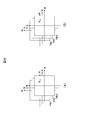
- FIG. 2 is a diagram showing an example of torque ripple, which is a circumferential component of the pulsation of the electromagnetic force of the motor 300 when this embodiment is not applied.
- FIG. 2 (A) shows the torque acting on the shaft of the motor 300
- FIG. 2 (B) shows the circumferential component of the pulsation of the electromagnetic force caused by the magnetic circuit of the motor 300
- FIG. 2 (C) shows the first.
- the circumferential component of the pulsation of the electromagnetic force generated in the motor due to the control of the inverter circuit 201 is shown in FIG. 2 (D). It is a figure which shows the circumferential component.
- the horizontal axis represents the electrical angle and the vertical axis represents the torque.
- FIG. 2 (B), FIG. 2 (C) and FIG. 2 (D) the torque ripple which is a circumferential component of the pulsation of the electromagnetic force due to each factor in the motor 300 is shown.
- FIG. 3 is a diagram showing an example of torque ripple, which is a circumferential component of the pulsation of the electromagnetic force of the motor 300 when the present embodiment is applied.
- FIG. 3A shows the torque of the shaft of the motor 300
- FIG. 3B shows the circumferential component of the pulsation of the electromagnetic force caused by the magnetic circuit of the motor 300
- FIG. 3C shows the first inverter.
- FIG. 3D shows a circumferential component of the pulsation of the electromagnetic force caused by the control of the circuit 201
- FIG. 3D shows a circumferential component of the pulsation of the electromagnetic force caused by the control of the second inverter circuit 202.
- the horizontal axis represents the electrical angle and the vertical axis represents the torque.
- FIG. 3B, FIG. 3C, and FIG. 3D similarly to FIG. 2, the torque ripple which is a circumferential component of the pulsation of the electromagnetic force due to each factor in the motor 300 is shown.
- the torque ripple finally generated by the motor 300 can be reduced by adjusting the phase of the pulsation of the electromagnetic force of three factors by the control described later.
- the controllable elements are the electromagnetic force pulsation caused by the control of the first inverter circuit 201 and the electromagnetic force pulsation caused by the control of the second inverter circuit 202.
- the control unit 208 controls the phase ⁇ I1 of the electromagnetic force pulsation caused by the control of the first inverter circuit 201 and the control of the second inverter circuit 202 with reference to the electromagnetic force pulsation caused by the magnetic circuit of the motor 300.
- the phase ⁇ I2 of the pulsation of the electromagnetic force caused by the above is adjusted.
- the adjustment of the phase ⁇ I1 of the pulsation of the electromagnetic force caused by the control of the first inverter circuit 201 is the phase of the PWM carrier signal used to generate the PWM signal for controlling the first inverter circuit 201 (carrier phase ⁇ C1 ).
- the adjustment of the phase ⁇ I2 of the pulsation of the electromagnetic force caused by the control of the second inverter circuit 202 is the phase of the PWM carrier signal used to generate the PWM signal for controlling the second inverter circuit 202 (carrier phase ⁇ C2 ). To adjust.
- the pulsation of the electromagnetic force caused by the control of the first inverter circuit 201 is applied to the pulsation of the electromagnetic force caused by the magnetic circuit of the motor 300 shown in FIG. 3 (B). For example, shift by 20 degrees. Further, for example, with respect to the pulsation of the electromagnetic force caused by the control of the second inverter circuit 202 shown in FIG. 3 (D) and the pulsation of the electromagnetic force caused by the magnetic circuit of the motor 300 shown in FIG. 3 (B). For example, shift by 40 degrees.
- the pulsation generated in the torque of the shaft of the motor 300 can be suppressed, and the vibration and noise of the motor 300 can be suppressed.
- the carrier phases ⁇ C1 and ⁇ C2 are adjusted, respectively, and the phase ⁇ I1 of the circumferential component in the electromagnetic force pulsation caused by the control of the first inverter circuit 201 and the control of the second inverter circuit 202 are caused.
- the torque ripple which is the circumferential component of the electromagnetic force pulsation generated in the motor 300
- the phase ⁇ I2 of the circumferential component in the electromagnetic force pulsation is reduced by adjusting the phase ⁇ I2 of the circumferential component in the electromagnetic force pulsation.
- the electromagnetic excitation force which is a radial component of the electromagnetic force pulsation generated in the motor 300.
- the phase of the radial component in the electromagnetic force pulsation caused by the control of the first inverter circuit 201 and the electromagnetic force pulsation caused by the control of the second inverter circuit 202 By adjusting the phase of the radial component, the electromagnetic excitation force, which is the radial component of the electromagnetic force pulsation generated in the motor 300, can be reduced.
- FIG. 4 (A) and 4 (B) are diagrams showing a motor pulsation map.
- FIG. 4A is a pulsation map of the electromagnetic force for the circumferential component of the motor 300
- FIG. 4B is a pulsation map of the electromagnetic force for the radial component of the motor 300. Both are stored in advance in the storage unit 218.
- the pulsation map of the electromagnetic force for the circumferential component of the motor 300 includes the current command values Id and Iq when controlling the motor 300 and the electromagnetic force caused by the magnetic circuit of the motor 300. It is a map associating with the phase ⁇ Tr of the pulsation of. This map is set corresponding to the DC voltages Vdc1, Vdc2, and Vdc3 of the DC power supply 100, respectively.
- Vdc1, Vdc2, and Vdc3 the motor pulsation map for the circumferential component is shown. May be set corresponding to a plurality of DC voltages, and may be other than three.
- the pulsation map of the electromagnetic force for the radial component of the motor 300 shows the current command values Id and Iq when controlling the motor 300 and the pulsation caused by the magnetic circuit of the motor 300. It is a map associated with the phase ⁇ Tr. This map is set corresponding to the DC voltages Vdc1, Vdc2, and Vdc3 of the DC power supply 100, respectively.
- Vdc1, Vdc2, and Vdc3 for convenience of explanation, an example in which a motor pulsation map for radial components is set for three DC voltages Vdc1, Vdc2, and Vdc3 is shown, but the motor pulsation map for radial components is shown. It suffices as long as it is set corresponding to a plurality of DC voltages, and may be other than three.
- the motor pulsation maps shown in FIGS. 4 (A) and 4 (B) are stored in advance using experimental values and design values. For example, when the motor drive system shown in FIG. 1 is operated and the DC voltage Vdc1 of the DC power supply 100 is used, a certain current command value Id, Iq and the pulsation of the electromagnetic force caused by the magnetic circuit of the motor 300 in that case Find the phase ⁇ Tr and use it as a map. Then, the current command values Id and Iq are variously changed to obtain the phase ⁇ Tr of each electromagnetic force pulsation, which is used as a map. Hereinafter, similarly, the DC voltage of the DC power supply 100 is changed to obtain a map.
- the motor pulsation map shows the magnitude of the pulsation of the electromagnetic force (torque ripple generated in the circumferential direction and the electromagnetic excitation force generated in the radial direction) caused by the magnetic circuit of the motor 300 based on the current command values id and iq, and the magnitude of the electromagnetic excitation force of the motor 300.
- the reference phase with respect to the electric angle is also stored in advance.
- the current command values Id, Iq refer to the map for the circumferential component shown in FIG. 4 (A).
- the phase ⁇ Tr of the electromagnetic force pulsation corresponding to is obtained with reference to the map for the radial component shown in FIG. 4 (B).
- FIG. 5 (A) and 5 (B) are diagrams showing a circumferential carrier phase map.
- FIG. 5A is a carrier phase map for the first circumferential component of the first inverter circuit 201
- FIG. 5B is a carrier phase map for the second circumferential component of the second inverter circuit 202. be. Both are stored in advance in the storage unit 218.
- the carrier phase map for the first circumferential component of the first inverter circuit 201 includes the current command values Id and Iq when controlling the motor 300 and the control of the first inverter circuit 201. It is a map associated with the carrier phase ⁇ C1 for reducing the circumferential component of the electromagnetic force pulsation caused by.
- the carrier phase map for the second circumferential component of the second inverter circuit 202 includes the current command values Id and Iq when controlling the motor 300 and the control of the second inverter circuit 202. It is a map associated with the carrier phase ⁇ C2 for reducing the circumferential component of the electromagnetic force pulsation caused by.
- These maps are set corresponding to the DC voltages Vdc1, Vdc2, and Vdc3 of the DC power supply 100, respectively.
- the carrier phase map for the first circumferential component and the carrier for the second circumferential component are provided for the three DC voltages Vdc1, Vdc2, and Vdc3.
- An example in which each phase map is set is shown, but these maps may be set corresponding to a plurality of DC voltages, and may be other than three.
- FIG. 6 (A) and 6 (B) are diagrams showing a radial carrier phase map.
- FIG. 6A is a carrier phase map for the first radial component of the first inverter circuit 201
- FIG. 6B is a carrier phase map for the second radial component of the second inverter circuit 202. be. Both are stored in advance in the storage unit 218.
- the carrier phase map for the first radial component of the first inverter circuit 201 includes the current command values Id and Iq when controlling the motor 300 and the control of the first inverter circuit 201. It is a map associated with the carrier phase ⁇ C1 for reducing the radial component of the electromagnetic force pulsation caused by.
- the carrier phase map for the second radial component of the second inverter circuit 202 includes the current command values Id and Iq when controlling the motor 300 and the control of the second inverter circuit 202. It is a map associated with the carrier phase ⁇ C2 for reducing the radial component of the electromagnetic force pulsation caused by.
- These maps are set corresponding to the DC voltages Vdc1, Vdc2, and Vdc3 of the DC power supply 100, respectively.
- the carrier phase map for the first radial component and the carrier for the second radial component are provided for the three DC voltages Vdc1, Vdc2, and Vdc3.
- An example in which each phase map is set is shown, but these maps may be set corresponding to a plurality of DC voltages, and may be other than three.
- the carrier phases ⁇ C1 and ⁇ C2 in the circumferential carrier phase maps of FIGS. 5 (A) and 5 (B) and the radial carrier phase maps of FIGS. 6 (A) and 6 (B) are shown in FIGS. It is represented with reference to the phase ⁇ Tr in the motor pulsation map of 4 (A) and 4 (B), respectively. That is, the phase difference between the electromagnetic force pulsation caused by the magnetic circuit of the motor 300 and each PWM carrier signal for reducing the electromagnetic force pulsation caused by the control of the first inverter circuit 201 and the second inverter circuit 202 is determined. It is represented by the circumferential carrier phase map of FIGS. 5 (A) and 5 (B) and the radial carrier phase map of FIGS. 6 (A) and 6 (B), respectively.
- the PWM carrier phase maps of the circumferential components shown in FIGS. 5 (A) and 5 (B) are stored in advance using experimental values and design values. For example, when the motor drive system shown in FIG. 1 is operated and the DC voltage Vdc1 of the DC power supply 100 is used, certain current command values Id and Iq and the control of the first inverter circuit 201 and the second inverter circuit 202 in that case are controlled.
- the carrier phases ⁇ C1 and ⁇ C2 that reduce the circumferential component of the pulsation of the electromagnetic force caused by the above are obtained and used as a map.
- the phase of the PWM carrier signal of the first inverter circuit 201 is shifted, and the phase when the torque ripple of the motor 300 becomes the smallest is obtained as the carrier phase ⁇ C1 .
- the second inverter circuit 202 if the phase of the PWM carrier signal used for the PWM control of the inverter circuits 201 and 202 is shifted to the phases ⁇ C1 and ⁇ C2 , it means that the pulsation of the electromagnetic force in the circumferential direction caused by these controls can be minimized. ..
- the current command values Id and Iq are changed in various ways to obtain the carrier phases ⁇ C1 and ⁇ C2 in each case, which are used as a map.
- the DC voltage of the DC power supply 100 is changed to obtain a map.
- the PWM carrier phase maps of the radial components shown in FIGS. 6 (A) and 6 (B) are also stored in advance using experimental values and design values. For example, when the motor drive system shown in FIG. 1 is operated and the DC voltage Vdc1 of the DC power supply 100 is used, certain current command values Id and Iq and the control of the first inverter circuit 201 and the second inverter circuit 202 in that case are controlled.
- the carrier phases ⁇ C1 and ⁇ C2 that reduce the radial component of the pulsation of the electromagnetic force caused by the above are obtained and used as a map.
- the current command values Id and Iq are changed in various ways to obtain the carrier phases ⁇ C1 and ⁇ C2 in each case, which are used as a map.
- the DC voltage of the DC power supply 100 is changed to obtain a map.
- the map for the circumferential component shown in FIGS. 5 (A) and 5 (B) is referred to.
- the carrier phases ⁇ C1 and ⁇ C2 corresponding to the current command values Id and Iq are referred to with reference to the maps for the radial components shown in FIGS. 6 (A) and 6 (B).
- FIG. 7 is a diagram showing the relationship between the rotation speed of the motor 300 and the excitation frequency (frequency of pulsation in the radial direction).
- the horizontal axis represents the rotation speed of the motor 300, and the vertical axis represents the excitation frequency.
- Asynchronous PWM control is used until the rotation speed of the motor 300 is up to 12000 rpm, and synchronous PWM control is used when the rotation speed of the motor 300 exceeds 12000 rpm.
- the electric angle (fundamental wave current) that rotates the motor 300 is defined as the frequency f1 [Hz].
- the relationship between the rotation speed N [rpm] of the motor 300 and the electric angular frequency f1 is expressed by the following equation (1).
- P is the number of poles of the motor 300.
- f1 N / 60 ⁇ P / 2 [rpm] ⁇ ⁇ ⁇ (1)
- the excitation frequency f6 of the sixth rotation (electrical angle) of the motor 300 is represented by the following equation (2).
- the illustrated f6 is the rotation 6th order (electrical angle) excitation frequency f6
- the illustrated f12 is the rotation 12th order (electrical angle) excitation frequency f12.
- the excitation frequencies f6 and f12 increase linearly from the area of asynchronous PWM control to the area of synchronous PWM control.
- the carrier frequency fc is constant in asynchronous PWM control.
- the sideband wave components of the carrier frequencies fc and fc ⁇ 3f1 are the 0th-order excitation frequencies of the annulus.
- the 0th order of the annulus is the rotation order of the radial pulsation of the motor 300.
- the radial component of the electromagnetic force generated in the gap of the motor 300 which changes uniformly over time in the radial direction, is referred to as an annular zero-order mode.
- the pulsation of the electromagnetic force in the radial direction of the motor 300 is reduced for the radial pulsation of the 0th order of the annulus.
- the frequencies f6 and f12 of the pulsation of the electromagnetic force in the radial direction caused by the magnetic circuit of the motor 300 and the radial directions caused by the control of the inverter circuits 201 and 202 overlap.
- the radial electromagnetic force pulsation caused by the magnetic circuit of the motor 300 and the radial electromagnetic force pulsation caused by the control of the inverter circuits 201 and 202 have the same frequency.
- FIG. 8A and 8B are diagrams showing the frequency of the voltage command and the carrier frequency fc.
- FIG. 8A shows the waveform of the first inverter circuit 201
- FIG. 8B shows the waveform of the second inverter circuit 202. show.
- the left side of each figure shows the case where the rotation speed of the motor 300 is low
- the right side of each figure shows the case where the rotation speed of the motor 300 is high.
- the control of the control unit 208 shown in FIG. 1 is synchronous PWM control, and the control unit 208 controls the frequency of the voltage command and the carrier frequency fc.
- the frequency of the voltage command is the frequency f1 [Hz] of the electric angle (fundamental wave current) that turns the motor 300.
- the carrier frequency fc is controlled to form a PWM carrier signal of 9 pulses for each cycle of the voltage command frequency f1.
- NS As shown on the right side of FIGS. 8 (A) and 8 (B), similarly, the carrier frequency fc forms a PWM carrier signal of 9 pulses for each cycle of the voltage command frequency f1 even at high rotation speeds. Be controlled.
- the waveform obtained by the first inverter circuit 201 and the waveform obtained by the second inverter circuit 202 are similar waveforms.
- the frequency of the PWM carrier signal may be an integral multiple of the frequency of the voltage command.
- this integral multiple it is preferable to control this integral multiple to be an odd integer multiple, or to control it to be an integral multiple of a multiple of 3.
- the frequency of the PWM carrier signal used in the PWM control of the first inverter circuit 201 and the second inverter circuit 202 is set to the frequency f1 of the voltage command for driving the motor 300.
- the carrier frequency fc is adjusted so as to be an integral multiple of the frequency of the voltage command to be driven.
- the pulsation of the electromagnetic force caused by the magnetic circuit of the motor 300 is shifted by shifting the phase of the pulsation of the electromagnetic force caused by the control of the inverter circuits 201 and 202 by the control described later. Can be offset.
- FIG. 9 is a flowchart showing the processing of the control unit 208 of the motor control device 200.
- the flowchart shown in FIG. 9 is executed at regular intervals or every time a torque command value T * is input.
- the program shown in this flowchart can be executed by a computer equipped with a CPU, memory, and the like. All processing or some processing may be realized by a hard logic circuit. Further, this program can be provided by being stored in a storage medium of the motor control device 200 in advance. Alternatively, the program can be stored and provided in an independent storage medium, or the program can be recorded and stored in the storage medium of the motor control device 200 via a network line. It may be supplied as a computer-readable computer program product in various forms such as a data signal (carrier wave).
- step S901 of FIG. 9 the control unit 208 receives the torque command value T * from the host controller or the like. Then, in step S902, the control unit 208 creates the current command values Id and Iq from the received torque command value T *.
- step S903 the control unit 208 adjusts the frequency of the PWM carrier signal to be an integral multiple of the frequency of the voltage command, as described with reference to FIGS. 8A and 8B. do. At this time, for example, it is desirable to adjust the integer multiple to an odd integer multiple and to an integer multiple of a multiple of 3.
- step S904 the control unit 208 selects the pulsating component to be reduced. That is, when the rotation speed of the motor 300 is lower than a predetermined value, a circumferential component is selected, and when the rotation speed of the motor 300 is a predetermined value or more, a radial component is selected.
- the value of the rotation speed of the motor 300 is determined based on the rotation position ⁇ from the magnetic pole position detector 207.
- the control unit 208 determines the torque ripple generated in the circumferential direction among the electromagnetic force pulsations caused by the magnetic circuit of the motor 300 and the electromagnetic force pulsation caused by the magnetic circuit of the motor 300 based on the rotation speed of the motor 300. Select one of the electromagnetic excitation forces generated in the radial direction.
- step S905 the control unit 208 searches for the motor pulsation map stored in the storage unit 218.
- the motor pulsation map includes a map for the circumferential component shown in FIG. 4 (A) and a map for the radial component shown in FIG. 4 (B). Since the pulsating component to be reduced is selected in step S904, the map corresponding to the selected pulsating component is searched.
- the control unit 208 detects the DC voltage value of the DC power supply 100 from the voltage detector 101. That is, when the rotation speed is lower than the predetermined value, among the maps for the three circumferential components shown in FIG.
- the map corresponding to the detected DC voltage value of the DC power supply 100 is the current command value Id, Iq.
- the phase ⁇ Tr of the pulsation of the electromagnetic force caused by the magnetic circuit of the motor 300 is acquired by searching based on.
- the map corresponding to the detected DC voltage value of the DC power supply 100 is based on the current command values Id and Iq. And obtains the phase ⁇ Tr of the pulsation of the electromagnetic force caused by the magnetic circuit of the motor 300.
- a change in the DC voltage of the DC power supply 100 changes the amplitude of the pulsation of the electromagnetic force caused by the magnetic circuit of the motor 300.
- the map corresponding to the DC voltage value detected by the voltage detector 101 is referred to, so that the amplitude can be changed. can do.
- step S906 the control unit 208 estimates the phase of the pulsation caused by the magnetic circuit of the motor 300 from the phase ⁇ Tr searched in step S905.
- the control unit 208 estimates the phase of the pulsation caused by the magnetic circuit of the motor 300 from the phase ⁇ Tr searched in step S905.
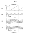
- FIG. 10 is a diagram showing torque ripple when this embodiment is applied.
- FIG. 10A is a diagram showing the magnetic position of the motor 300, in which the horizontal axis represents time and the vertical axis represents the electric angle.
- FIG. 10B shows the torque of the shaft of the motor 300, the horizontal axis represents time, and the vertical axis represents torque.
- FIG. 10C is a diagram showing a PWM carrier signal and voltage command of the first inverter circuit 201
- FIG. 10D is a diagram showing a PWM carrier signal and voltage command of the second inverter circuit 202
- the horizontal axis is time.
- the vertical axis represents the voltage.
- the magnetic position of the motor 300 changes every 360 degrees of the electric angle as the motor 300 rotates, and the rotation angle of 0 degrees becomes the reference position.
- the control unit 208 estimates the phase of the pulsation caused by the magnetic circuit of the motor 300 by using the detection signal of the magnetic pole position detector 207 attached to the motor 300 and the current command value to the motor 300. Since the pulsation of the electromagnetic force caused by the magnetic circuit with respect to the rotation angle of the motor 300 can be estimated, the carrier phase ⁇ C1 and the carrier phase ⁇ C1 and as shown in FIGS. ⁇ C2 can be adjusted.
- the control unit 208 searches for the carrier phase map stored in the storage unit 218.
- the carrier phase map includes the circumferential carrier phase map shown in FIGS. 5 (A) and 5 (B) and the radial carrier phase map shown in FIGS. 6 (A) and 6 (B). ..
- the map corresponding to the selected pulsating component is searched.
- the control unit 208 detects the DC voltage value of the DC power supply 100 from the voltage detector 101. That is, when the rotation speed is lower than the predetermined value, the map corresponding to the detected DC voltage value of the DC power supply 100 among the maps for the three circumferential components shown in FIGS. 5 (A) and 5 (B), respectively. Is searched based on the current command values Id and Iq, respectively, and the carrier phases ⁇ C1 and ⁇ C2 are acquired.
- the map corresponding to the detected DC voltage value of the DC power supply 100 among the maps for the three radial components shown in FIGS. 6 (A) and 6 (B) is used as the current. Search based on the command values Id and Iq, respectively, and acquire the carrier phases ⁇ C1 and ⁇ C 2.
- step S908 of FIG. 9 the control unit 208 shifts the PWM carrier signal to the first inverter circuit 201 by the phase ⁇ C1 with reference to the pulsation of the electromagnetic force caused by the magnetic circuit of the motor 300. Further, the PWM carrier signal with respect to the second inverter circuit 202 is shifted by the phase ⁇ C2 with reference to the pulsation of the electromagnetic force caused by the magnetic circuit of the motor 300.
- step S909 the control unit 208 drives the first inverter circuit 201 and the second inverter circuit 202 to output an AC voltage to the motor 300.
- phase of the PWM carrier signal is shifted with reference to the pulsation of the electromagnetic force caused by the magnetic circuit of the motor 300 by the combined wave of the harmonic currents energized by the first inverter circuit and the second inverter circuit. do.
- pulsation caused by the magnetic circuit of the motor 300 can be suppressed.
- FIG. 3C shows an example of shifting the pulsation of the electromagnetic force caused by the control of the first inverter circuit 201 by 20 degrees
- FIG. 3D shows the pulsation of the electromagnetic force caused by the control of the second inverter circuit 202. Is shown by shifting 40 degrees.
- the adjustment of the phase ⁇ I1 of the pulsation of the electromagnetic force caused by the control of the first inverter circuit 201 is performed by adjusting the carrier phase ⁇ C1 of the first inverter circuit 201.
- the phase ⁇ I2 of the pulsation of the electromagnetic force caused by the control of the second inverter circuit 202 is adjusted by adjusting the carrier phase ⁇ C2 of the second inverter circuit 202.
- torque ripple generated in the axial direction of the motor 300 and electromagnetic excitation force generated in the radial direction of the motor 300 can be suppressed, and vibration and noise of the motor 300 can be suppressed. It can be suppressed.
- the radial carrier phase maps shown in FIGS. 6 (A) and 6 (B) are selected and used. That is, one of the torque ripple generated in the circumferential direction of the pulsation caused by the magnetic circuit of the motor 300 and the electromagnetic exciting force generated in the radial direction of the pulsation caused by the magnetic circuit of the motor 300 based on the rotational speed of the motor 300. Select to shift the phase of the PWM carrier signal to reduce the selected torque ripple or electromagnetic excitation force.
- the motor pulsation maps shown in FIGS. 4 (A) and 4 (B), FIGS. 5 (A), and 5 (B) are shown according to the DC voltage value of the DC power supply 100 detected by the voltage detector 101.
- the circumferential carrier phase map shown in B) and the radial carrier phase map shown in FIGS. 6 (A) and 6 (B) are selected and used. That is, the phase shift amount of the PWM carrier signal is adjusted based on the DC voltage applied to the first inverter circuit 201 and the second inverter circuit 202.
- the amplitude of the pulsation of the electromagnetic force caused by the control of the first inverter circuit 201 and the second inverter circuit 202 changes due to the change in the DC voltage of the DC power supply 100, but even if these amplitudes change. It is possible to secure the effect of reducing the torque ripple and the electromagnetic excitation force when superposed with the pulsation of the electromagnetic force caused by the magnetic circuit of the motor 300.
- FIG. 11A is a diagram showing the magnetic position of the motor 300, in which the horizontal axis represents time and the vertical axis represents the electric angle.
- FIG. 11B shows the torque ripple of the shaft of the motor 300, where the horizontal axis represents time and the vertical axis represents torque.
- FIG. 11C is a diagram showing a sixth-order electric angle component of torque ripple, and
- FIG. 11D is a diagram showing a twelfth-order electric angle component of torque ripple.
- the horizontal axis represents time and the vertical axis represents torque. ..
- the torque ripple on the shaft of the motor 300 shown in FIG. 11B indicates the pulsation of the electromagnetic force caused by the magnetic circuit of the motor 300.
- the pulsation of the electromagnetic force caused by the magnetic circuit of the motor 300 shown in FIG. 11 (B) is cut out for one electric angle cycle (360 degrees) shown in FIG. 11 (A), and the component analysis is performed. , FIG. 11 (D). That is, the waveform of FIG.
- 11C has six pulsations of the electromagnetic force in one cycle of the electric angle (360 degrees), and pulsates six times for one rotation of the electric angle, so that it is called a sixth-order component of the electric angle.
- the waveform of FIG. 11 (D) has 12 pulsations of electromagnetic force in one cycle of electric angle (360 degrees), and pulsates 12 times for one rotation of electric angle, so that it is called an electric angle 12th order component.
- FIG. 12 is a diagram showing pulsation when this embodiment is applied.
- 12 (A) shows the torque of the shaft of the motor 300
- FIG. 12 (B) shows the pulsation of the electromagnetic force caused by the magnetic circuit of the motor 300
- FIG. 12 (C) shows the control of the first inverter circuit 201
- FIG. 12 (D) is a diagram showing the pulsation of the electromagnetic force caused by the control of the second inverter circuit 202.
- the horizontal axis represents the electrical angle and the vertical axis represents the torque.
- step S908 of FIG. 9 In the control for reducing the pulsation of the electromagnetic force of the sixth-order electric angle component, the same processing as in steps S901 to S907 and S909 described with reference to FIG. 9 is performed, but in step S908 of FIG. 9, the following processing is performed. ..
- the control unit 208 sets the phase ⁇ I1 of the electromagnetic force pulsation caused by the control of the first inverter circuit 201 with reference to the electromagnetic force pulsation caused by the magnetic circuit of the motor 300. Shift 30 degrees. Further, as shown in FIG. 12D, the control unit 208 uses the pulsation of the electromagnetic force caused by the magnetic circuit of the motor 300 as a reference, and the phase ⁇ of the pulsation of the electromagnetic force caused by the control of the second inverter circuit 202. Shift I2 by 30 degrees.
- FIG. 3 is a diagram showing the pulsation of the electromagnetic force of the motor 300 when the present embodiment is applied.
- step S908 of FIG. Performs the following processing.
- the control unit 208 sets the phase ⁇ I1 of the electromagnetic force pulsation caused by the control of the first inverter circuit 201 with reference to the electromagnetic force pulsation caused by the magnetic circuit of the motor 300. Shift 20 degrees. Further, as shown in FIG. 3D, the control unit 208 uses the pulsation of the electromagnetic force caused by the magnetic circuit of the motor 300 as a reference, and the phase ⁇ of the pulsation of the electromagnetic force caused by the control of the second inverter circuit 202. Shift I2 by 40 degrees.
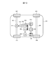
- FIG. 13 is a configuration diagram of the electric vehicle system according to the present embodiment. As shown in FIG. 13, the electric vehicle system has a power train to which the motor 300 is applied as a motor / generator, and travels by using the rotational driving force of the motor 300.
- the electric vehicle system will be described by taking a hybrid system as an example.
- a front wheel axle 801 is rotatably supported on the front portion of the electric vehicle 800, and front wheels 802 and 803 are provided at both ends of the front wheel axle 801.
- a rear wheel axle 804 is rotatably supported at the rear portion of the electric vehicle 800, and rear wheels 805 and 806 are provided at both ends of the rear wheel axle 804.
- a differential gear 811 which is a power distribution mechanism is provided in the central portion of the front wheel axle 801 to distribute the rotational driving force transmitted from the engine 810 via the transmission 812 to the left and right front wheel axles 801. ing.
- the engine 810 and the motor 300 are mechanically connected to each other via a belt between a pulley provided on the crankshaft of the engine 810 and a pulley provided on the rotating shaft of the motor 300.
- the rotational driving force of the motor 300 can be transmitted to the engine 810, and the rotational driving force of the engine 810 can be transmitted to the motor 300.
- the rotor rotates by supplying the three-phase AC power controlled by the motor control device 200 having the inverter circuits 201 and 202 built-in to the coil of the stator, and the motor 300 rotates according to the three-phase AC power. Generates driving force.
- the motor control device 200 is the device described above in this embodiment.
- the motor 300 while the motor 300 is controlled by the motor control device 200 and operates as an electric motor, the rotor rotates in response to the rotational driving force of the engine 810, so that an electromotive force is induced in the coil of the stator, resulting in three phases. It operates as a generator that generates AC power.
- the motor control device 200 is a power conversion device that converts DC power supplied from a DC power source 100, which is a high-pressure battery, into three-phase AC power, and is used as a stator coil of the motor 300 according to a magnetic position according to an operation command value. Controls the flowing three-phase alternating current.
- the three-phase AC power generated by the motor 300 is converted into DC power by the motor control device 200 to charge the DC power supply 100.
- the DC power supply 100 is electrically connected to the low voltage battery 823 via a DC-DC converter 824.
- the low-voltage battery 823 constitutes a low-voltage (14V) system power supply for the electric vehicle 800, and is used as a power supply for a starter 825, a radio, a light, etc. that initially starts (cold start) the engine 810.
- the vibration and noise of the motor 300 are generated by the exciting force generated by the electromagnetic force, which is transmitted to the main body of the motor 300 and the attached structure and shakes each part, so that the vibration noise is generated. Further, when the frequency overlaps with the intrinsic mode of the structure and the frequency and the excitation mode of the exciting force, a resonance state occurs and the vibration noise is amplified. In the present embodiment, the vibration and noise of the motor 300 can be reduced, and further, the vibration and noise of the electric vehicle 800 on which the motor 300 is mounted can be reduced.
- the motor control device 200 includes a redundant first inverter circuit 201 and a second inverter circuit 202 that control the motor 300, and a control unit 208 that controls the first inverter circuit 201 and the second inverter circuit 202.
- the first inverter circuit 201 converts DC power into AC power based on the PWM signal generated by using the first carrier signal
- the second inverter circuit 202 is generated by using the second carrier signal.
- the DC power is converted into AC power based on the PWM signal
- the control unit 208 sets the phases of the first carrier signal and the second carrier signal with reference to the pulsation of the electromagnetic force caused by the magnetic circuit of the motor 300. Shift each. As a result, vibration and noise generated in the motor can be suppressed.
- the motor control method is a motor control including a redundant first inverter circuit 201 and a second inverter circuit 202 for controlling the motor, and a control unit 208 for controlling the first inverter circuit 201 and the second inverter circuit 202.
- a motor control method in the device 200 in which the first inverter circuit 201 converts DC power into AC power based on the PWM signal generated by using the first carrier signal, and the second inverter circuit 202 converts the DC power into AC power.
- the DC power is converted into AC power based on the PWM signal generated by using the carrier signal of 2
- the control unit converts the first carrier signal and the pulsation of the electromagnetic force caused by the magnetic circuit of the motor 300 as a reference.
- a motor control method for shifting the phase of each of the second carrier signals As a result, vibration and noise generated in the motor can be suppressed.
Landscapes
- Engineering & Computer Science (AREA)
- Power Engineering (AREA)
- Transportation (AREA)
- Mechanical Engineering (AREA)
- Life Sciences & Earth Sciences (AREA)
- Sustainable Development (AREA)
- Sustainable Energy (AREA)
- Control Of Ac Motors In General (AREA)
- Control Of Motors That Do Not Use Commutators (AREA)
- Inverter Devices (AREA)
Priority Applications (3)
| Application Number | Priority Date | Filing Date | Title |
|---|---|---|---|
| US17/916,707 US12199539B2 (en) | 2020-04-06 | 2021-01-22 | Motor control device, electric vehicle, and motor control method |
| JP2022514314A JP7319459B2 (ja) | 2020-04-06 | 2021-01-22 | モータ制御装置、電動車両、およびモータ制御方法 |
| CN202180024506.4A CN115336168B (zh) | 2020-04-06 | 2021-01-22 | 马达控制装置、电动车辆以及马达控制方法 |
Applications Claiming Priority (2)
| Application Number | Priority Date | Filing Date | Title |
|---|---|---|---|
| JP2020068103 | 2020-04-06 | ||
| JP2020-068103 | 2020-04-06 |
Publications (1)
| Publication Number | Publication Date |
|---|---|
| WO2021205710A1 true WO2021205710A1 (ja) | 2021-10-14 |
Family
ID=78022703
Family Applications (1)
| Application Number | Title | Priority Date | Filing Date |
|---|---|---|---|
| PCT/JP2021/002146 Ceased WO2021205710A1 (ja) | 2020-04-06 | 2021-01-22 | モータ制御装置、電動車両、およびモータ制御方法 |
Country Status (4)
| Country | Link |
|---|---|
| US (1) | US12199539B2 (https=) |
| JP (1) | JP7319459B2 (https=) |
| CN (1) | CN115336168B (https=) |
| WO (1) | WO2021205710A1 (https=) |
Families Citing this family (2)
| Publication number | Priority date | Publication date | Assignee | Title |
|---|---|---|---|---|
| US12240334B2 (en) * | 2021-03-09 | 2025-03-04 | Shanghai XPT Technology Limited | Vehicle control method and vehicle drive system |
| DE112022001154T5 (de) * | 2021-04-22 | 2023-12-21 | Hitachi Astemo, Ltd. | Motorsteuervorrichtung und motorsteuerverfahren |
Citations (3)
| Publication number | Priority date | Publication date | Assignee | Title |
|---|---|---|---|---|
| JP2011151916A (ja) * | 2010-01-20 | 2011-08-04 | Mitsubishi Electric Corp | 交流回転機の制御装置 |
| JP2014003783A (ja) * | 2012-06-18 | 2014-01-09 | Mitsubishi Electric Corp | 電力変換器制御装置および多重巻線型電動機駆動装置 |
| WO2018087892A1 (ja) * | 2016-11-11 | 2018-05-17 | 三菱電機株式会社 | 電力変換装置 |
Family Cites Families (7)
| Publication number | Priority date | Publication date | Assignee | Title |
|---|---|---|---|---|
| AU2003203324A1 (en) * | 2002-02-09 | 2003-09-04 | Wei Huang | A switching pattern ac induction motor |
| JP5947705B2 (ja) * | 2012-12-12 | 2016-07-06 | トヨタ自動車株式会社 | 交流電動機の制御システム |
| JP6044585B2 (ja) | 2014-05-07 | 2016-12-14 | 株式会社デンソー | 多相交流モータの制御装置 |
| JP6179494B2 (ja) * | 2014-09-26 | 2017-08-16 | 株式会社デンソー | 交流電動機の制御装置 |
| CN110235357B (zh) * | 2017-01-30 | 2022-12-13 | 日立安斯泰莫株式会社 | 逆变器控制装置 |
| CN107994816B (zh) * | 2017-10-31 | 2020-08-25 | 宁波诺丁汉大学 | 一种电机系统及其优化控制方法 |
| JP6781190B2 (ja) * | 2018-05-23 | 2020-11-04 | ファナック株式会社 | モータ駆動装置及びモータ駆動方法 |
-
2021
- 2021-01-22 US US17/916,707 patent/US12199539B2/en active Active
- 2021-01-22 JP JP2022514314A patent/JP7319459B2/ja active Active
- 2021-01-22 WO PCT/JP2021/002146 patent/WO2021205710A1/ja not_active Ceased
- 2021-01-22 CN CN202180024506.4A patent/CN115336168B/zh active Active
Patent Citations (3)
| Publication number | Priority date | Publication date | Assignee | Title |
|---|---|---|---|---|
| JP2011151916A (ja) * | 2010-01-20 | 2011-08-04 | Mitsubishi Electric Corp | 交流回転機の制御装置 |
| JP2014003783A (ja) * | 2012-06-18 | 2014-01-09 | Mitsubishi Electric Corp | 電力変換器制御装置および多重巻線型電動機駆動装置 |
| WO2018087892A1 (ja) * | 2016-11-11 | 2018-05-17 | 三菱電機株式会社 | 電力変換装置 |
Also Published As
| Publication number | Publication date |
|---|---|
| CN115336168A (zh) | 2022-11-11 |
| US12199539B2 (en) | 2025-01-14 |
| CN115336168B (zh) | 2026-03-31 |
| JPWO2021205710A1 (https=) | 2021-10-14 |
| JP7319459B2 (ja) | 2023-08-01 |
| US20230155533A1 (en) | 2023-05-18 |
Similar Documents
| Publication | Publication Date | Title |
|---|---|---|
| JP5827026B2 (ja) | 回転電機及び回転電機駆動システム | |
| JP5781785B2 (ja) | 回転電機駆動システム | |
| JP5120586B2 (ja) | 界磁巻線型同期機 | |
| JP5718668B2 (ja) | 回転電機駆動システム | |
| JP7126150B2 (ja) | モータ | |
| JP2022018168A (ja) | モータ制御装置、機電一体ユニット、発電機システム、昇圧コンバータシステム、および電動車両システム | |
| JP2012222941A (ja) | 回転電機 | |
| US12491774B2 (en) | Motor control device, electromechanical integrated unit, boost converter system, electric vehicle system, and motor control method | |
| US12562657B2 (en) | Inverter control device, hybrid system, electromechanical integrated unit, electric vehicle system, and inverter control method | |
| US20230402953A1 (en) | Motor control device, electro-mechanical integrated unit, hybrid system, and electric power steering system | |
| JP7128456B2 (ja) | モータ | |
| CN102006006B (zh) | 用于电机的非正弦电流波形激励的系统和方法 | |
| JP7494393B2 (ja) | モータ制御装置、機電一体ユニット、ハイブリッドシステム、電動パワーステアリングシステム、およびモータ制御方法 | |
| JP2009077464A (ja) | 界磁巻線型同期機 | |
| JP7319459B2 (ja) | モータ制御装置、電動車両、およびモータ制御方法 | |
| JP5760895B2 (ja) | 回転電機制御システム | |
| Dajaku et al. | Opportunities of advanced multi-phase concentrated windings | |
| JP4155152B2 (ja) | 交流回転電機装置 | |
| JP2014039446A (ja) | 極数変換モータ装置 | |
| KR102199891B1 (ko) | 스위치드 릴럭턴스 모터의 제어 장치 | |
| JP6839896B2 (ja) | モータ制御装置および電動車両 | |
| CN112292810A (zh) | 马达控制装置 | |
| JP2019097301A (ja) | スイッチトリラクタンスモータの制御装置 | |
| JP2019149911A (ja) | スイッチトリラクタンスモータの制御装置 | |
| JP2013110942A (ja) | 回転電機及び回転電機制御システム |
Legal Events
| Date | Code | Title | Description |
|---|---|---|---|
| 121 | Ep: the epo has been informed by wipo that ep was designated in this application |
Ref document number: 21785546 Country of ref document: EP Kind code of ref document: A1 |
|
| ENP | Entry into the national phase |
Ref document number: 2022514314 Country of ref document: JP Kind code of ref document: A |
|
| NENP | Non-entry into the national phase |
Ref country code: DE |
|
| 122 | Ep: pct application non-entry in european phase |
Ref document number: 21785546 Country of ref document: EP Kind code of ref document: A1 |