WO2021200804A1 - 車両用前照灯及び車両用前照灯システム - Google Patents
車両用前照灯及び車両用前照灯システム Download PDFInfo
- Publication number
- WO2021200804A1 WO2021200804A1 PCT/JP2021/013246 JP2021013246W WO2021200804A1 WO 2021200804 A1 WO2021200804 A1 WO 2021200804A1 JP 2021013246 W JP2021013246 W JP 2021013246W WO 2021200804 A1 WO2021200804 A1 WO 2021200804A1
- Authority
- WO
- WIPO (PCT)
- Prior art keywords
- vehicle
- region
- signal indicating
- light
- turning
- Prior art date
- Legal status (The legal status is an assumption and is not a legal conclusion. Google has not performed a legal analysis and makes no representation as to the accuracy of the status listed.)
- Ceased
Links
Images











Classifications
-
- B—PERFORMING OPERATIONS; TRANSPORTING
- B60—VEHICLES IN GENERAL
- B60Q—ARRANGEMENT OF SIGNALLING OR LIGHTING DEVICES, THE MOUNTING OR SUPPORTING THEREOF OR CIRCUITS THEREFOR, FOR VEHICLES IN GENERAL
- B60Q1/00—Arrangement of optical signalling or lighting devices, the mounting or supporting thereof or circuits therefor
- B60Q1/02—Arrangement of optical signalling or lighting devices, the mounting or supporting thereof or circuits therefor the devices being primarily intended to illuminate the way ahead or to illuminate other areas of way or environments
- B60Q1/04—Arrangement of optical signalling or lighting devices, the mounting or supporting thereof or circuits therefor the devices being primarily intended to illuminate the way ahead or to illuminate other areas of way or environments the devices being headlights
-
- B—PERFORMING OPERATIONS; TRANSPORTING
- B60—VEHICLES IN GENERAL
- B60Q—ARRANGEMENT OF SIGNALLING OR LIGHTING DEVICES, THE MOUNTING OR SUPPORTING THEREOF OR CIRCUITS THEREFOR, FOR VEHICLES IN GENERAL
- B60Q1/00—Arrangement of optical signalling or lighting devices, the mounting or supporting thereof or circuits therefor
- B60Q1/02—Arrangement of optical signalling or lighting devices, the mounting or supporting thereof or circuits therefor the devices being primarily intended to illuminate the way ahead or to illuminate other areas of way or environments
- B60Q1/04—Arrangement of optical signalling or lighting devices, the mounting or supporting thereof or circuits therefor the devices being primarily intended to illuminate the way ahead or to illuminate other areas of way or environments the devices being headlights
- B60Q1/14—Arrangement of optical signalling or lighting devices, the mounting or supporting thereof or circuits therefor the devices being primarily intended to illuminate the way ahead or to illuminate other areas of way or environments the devices being headlights having dimming means
Definitions
- the present invention relates to a vehicle headlight and a vehicle headlight system including the vehicle headlight.
- a vehicle headlight that changes the light distribution pattern of the emitted light based on information from a detection device that detects another vehicle located in front of the vehicle is known.
- the following Patent Document 1 describes such a vehicle headlight, and the vehicle headlight is located in front of the vehicle and a light emitting unit capable of changing the light distribution pattern of the emitted light.
- This control unit controls the lamp so that the width of the region where the light irradiation is suppressed changes in the left-right direction according to the position of the other vehicle in the left-right direction.
- Patent Document 1 does not consider the dazzling of the driver of the other vehicle when the other vehicle turns. Further, when the region where the light irradiation is suppressed is formed in the light distribution pattern as described above, a part of the light distribution pattern is darker than the other regions of the light distribution pattern, so that the front of the own vehicle Visibility tends to decrease.
- the present invention is a vehicle headlight and a vehicle headlight that can suppress the dazzling of the driver of the other vehicle when the other vehicle turns and can suppress the deterioration of the front visibility of the own vehicle. It is an object of the present invention to provide a vehicle headlight system equipped with.
- the present invention is a vehicle headlight mounted on a vehicle, which emits light having a changeable light distribution pattern toward another vehicle located in front of the vehicle. It is detected by the detection device and a determination unit that determines information from the unit and a detection device that detects the other vehicle and generates a signal indicating a turning operation of the other vehicle, which is at least one of a turning notice and a turn.
- the control unit includes a control unit for inputting a signal indicating the other vehicle and a signal indicating the turning operation of the other vehicle, and the control unit is among the light distribution patterns when the signal indicating the other vehicle is input.
- At least the region including the first region that overlaps all of the visual recognition portions for the driver of the other vehicle to visually recognize the outside of the vehicle is the total light beam of the light from the light emitting unit as compared with before the signal indicating the other vehicle is input.
- the light emitting unit is controlled so as to be a dimmed region in which the amount is reduced and a signal indicating the turning operation of the other vehicle is further input in addition to the signal indicating the other vehicle, the light emitting unit is included in the dimmed region.
- the light emission is such that at least the first region spreads toward the turning direction side of the other vehicle after the signal indicating the other vehicle is input and before the signal indicating the turning operation of the other vehicle is input.
- the dimming region includes a second region that connects to the lower edge of the first region, with the left edge of the second region to the right of the left edge of the first region. It is characterized in that the right edge of the second region is located on the left side of the right edge of the first region.
- the turning notice may be, for example, a state in which the turn lamp of another vehicle is blinking.
- the turning direction side means a side on which another vehicle is scheduled to turn or a turning side when viewed from the own vehicle.
- the right turn lamp of the other vehicle blinks, or the other vehicle is turning to the right, that is, when the other vehicle is turning to the right.
- the turning direction side is on the right side when viewed from the own vehicle.
- the left turn lamp of the other vehicle blinks or is turning to the left, that is, when the other vehicle is turning to the left, the turning direction.
- the side is on the right side when viewed from the own vehicle.
- a visual recognition unit for the driver of another vehicle to visually recognize the outside of the vehicle for example, a front window or the like can be mentioned when the other vehicle is an oncoming vehicle, and for example, a side mirror when the other vehicle is a preceding vehicle.
- Rear window image pickup device that images the rear of the vehicle, and the like.
- this vehicle headlight when a signal indicating a turning operation of another vehicle is input to the control unit, at least the first region of the dimming region is input with a signal indicating another vehicle. It spreads toward the turning direction side compared to before the signal indicating the turning notice of the other vehicle is input later. Therefore, the region of the light distribution pattern in which the line of sight of the driver of the other vehicle moves may be darker than the other regions of the light distribution pattern. Therefore, according to this vehicle headlight, it is possible to suppress dazzling of the driver of the other vehicle when the other vehicle turns.
- the dimming region includes a second region connected to the lower edge of the first region, and the left edge of the second region is the first.
- the right edge of the second region is located to the right of the left edge of the first region, and the right edge of the second region is located to the left of the right edge of the first region.
- this vehicle headlight it is possible to suppress the dazzling of the driver of the other vehicle when the other vehicle turns, and it is possible to suppress the deterioration of the forward visibility in the own vehicle.
- the dimming region includes a third region connected to the upper edge of the first region, and the control unit receives a signal indicating the turning operation of the other vehicle in addition to the signal indicating the other vehicle.
- the light emitting unit may be controlled so that the edge of the third region on the turning direction side is located closer to the other vehicle than the edge of the first region on the turning direction side.
- the spread of the third region located above the first region toward the turning direction is suppressed.
- the proportion of the bright region in the light distribution pattern is larger than that in the case where the spread of the third region in the turning direction side is equivalent to the spread of the first region and the turning direction side. Therefore, it is possible to suppress a decrease in the front visibility of the own vehicle.
- the control unit receives the signal indicating the turning operation of the other vehicle in addition to the signal indicating the other vehicle, and the control unit receives the signal indicating the turning operation of the other vehicle. It is preferable to control the light emitting unit so that the edge on the turning direction side does not move from the position before the signal indicating the turning operation of the other vehicle is input.
- the dimming region includes the third region
- the position of the upper edge of the first region in the vertical direction is above the roof panel of the other vehicle and the light distribution pattern. It is preferably located below the center between the upper edge and the roof panel.
- the visible part of the other vehicle is generally located below the roof panel of the other vehicle. Therefore, if the upper edge of the first region is located above the roof panel, the entire visible portion can more reliably overlap the first region. Further, if the upper edge of the first region is located below the center between the upper edge of the light distribution pattern and the roof panel, it can be suppressed that the area of the third region becomes too small. .. Therefore, when another vehicle issues a turning notice, it is possible to further suppress the unnecessarily expanding of the dimming area, and it is possible to further suppress the deterioration of the front visibility of the own vehicle.
- control unit when the control unit further inputs a signal indicating the turning operation of the other vehicle in addition to the signal indicating the other vehicle, the control unit is at least the edge of the first region on the turning direction side of the dimming region.
- the light emitting unit may be controlled so as to move upward and away from the vertical line passing through the end of the other vehicle on the turning direction side.
- the ratio of the bright region to the changed light distribution pattern can be increased as compared with the case where the dimming region is widened while the edge of the dimming region on the turning direction side is parallel to the vertical line. Therefore, it is possible to further suppress the deterioration of the front visibility of the own vehicle.
- the determination unit determines the distance to the other vehicle based on the information from the detection device, and outputs a signal indicating the other vehicle to the control unit when the distance is equal to or less than a predetermined distance. May be good.
- dazzling to other vehicles is more likely to occur as the distance to other vehicles is shorter. Therefore, by inputting a signal indicating another vehicle to the control unit when the distance is less than a predetermined distance, dazzling to the other vehicle can be effectively suppressed. Further, when the distance to another vehicle is larger than a predetermined distance, the dimming area does not widen, so that the visibility of the own vehicle can be improved while suppressing the dazzling of the other vehicle.
- the vehicle headlight system of the present invention is characterized by including the vehicle headlight according to any one of the above and a detection device for detecting the other vehicle. Is.
- This vehicle headlight system is equipped with the vehicle headlights described in any of the above. Therefore, this vehicle headlight can suppress the dazzling of the driver of the other vehicle when the other vehicle turns, and can suppress the deterioration of the front visibility of the own vehicle.
- a vehicle headlight that can suppress the dazzling of the driver of the other vehicle when the other vehicle turns and can suppress the deterioration of the front visibility of the own vehicle and the said vehicle.
- a vehicle headlight system with a vehicle headlight can be provided.
- FIG. 1st Embodiment of this invention It is a top view which conceptually shows the vehicle which comprises the headlight for a vehicle and the headlight system for a vehicle according to 1st Embodiment of this invention. It is a side view which shows typically one light emitting unit shown in FIG. It is a front view which shows typically the light distribution pattern forming part shown in FIG. It is a figure which shows an example of the control flowchart of the control part in 1st Embodiment. It is a figure which shows the light distribution pattern of a high beam. It is a figure which shows an example of the light distribution pattern of the light emitted when the preceding vehicle is detected by the detection device. It is a figure which enlarges and shows the dimming region and its vicinity among the light distribution patterns shown in FIG.
- FIG. 9 It is a figure which shows an example of the light distribution pattern of the light emitted when an oncoming vehicle is detected by a detection device. It is a figure which enlarges and shows the dimming region and its vicinity among the light distribution patterns shown in FIG. It is a figure which shows the state which the turn lamp of the preceding vehicle blinks from the same viewpoint as FIG. It is a figure which shows the state which changed the light distribution pattern shown in FIG. 7 from the same viewpoint as FIG. It is a figure which shows the state which the turn lamp of an oncoming vehicle blinks from the same viewpoint as FIG. It is a figure which shows the state which changed the light distribution pattern shown in FIG. 9 from the same viewpoint as FIG.
- FIG. 1 is a plan view conceptually showing a vehicle 100 including a vehicle headlight and a vehicle headlight system according to the first embodiment.
- the vehicle 100 includes a vehicle headlight system 2
- the vehicle headlight system 2 includes a vehicle headlight 1 and another vehicle located in front of the vehicle 100.
- a detection device 20 for detecting the above is provided.
- the vehicle headlight 1 of the present embodiment is a headlight that can be mounted on an automobile as a vehicle.
- the vehicle headlight 1 mainly includes a pair of left and right light emitting units 10, a control unit CO, a determination unit 25, a pair of power supply circuits 30, and a memory ME.
- "right” means the right side from the viewpoint of the driver of the vehicle 100, which is the own vehicle
- "left” means the driver of the vehicle 100, which is the own vehicle. It means the left side in the viewpoint.
- the pair of light emitting units 10 have shapes that are substantially symmetrical with each other in the left-right direction of the vehicle 100, and emit light having a changeable light distribution pattern toward another vehicle located in front of the vehicle 100. .. Further, the configuration of one light emitting unit 10 is the same as the configuration of the other light emitting unit 10 except that the shape is substantially symmetrical. Therefore, in the following, one light emitting unit 10 will be described, and the other light emitting unit 10 will be omitted.
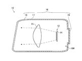
- FIG. 2 is a side view schematically showing one of the light emitting units 10 shown in FIG.
- the light emitting unit 10 includes a light distribution pattern forming unit 12, a projection lens 15, and a housing 16 as main configurations.
- the housing 16 is shown in a vertical cross section.
- the housing 16 includes a lamp housing 17, a front cover 18, and a back cover 19 as main configurations.
- the front of the lamp housing 17 has an opening, and the front cover 18 is fixed to the lamp housing 17 so as to close the opening. Further, an opening smaller than that in the front is formed behind the lamp housing 17, and a back cover 19 is fixed to the lamp housing 17 so as to close the opening.
- the space formed by the lamp housing 17, the front cover 18 that closes the front opening of the lamp housing 17, and the back cover 19 that closes the rear opening of the lamp housing 17 is a light chamber 10R.
- the light distribution pattern forming unit 12 and the projection lens 15 are housed therein.
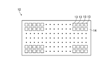
- FIG. 3 is a front view schematically showing the light distribution pattern forming portion 12 shown in FIG.
- the light distribution pattern forming unit 12 of the present embodiment includes a plurality of light emitting elements 13 that emit light, and a circuit board 14 on which the plurality of light emitting elements 13 are mounted.
- the plurality of light emitting elements 13 are arranged in a matrix to form rows in the vertical direction and the horizontal direction, and emit light toward the front.
- these light emitting elements 13 are LEDs (Light Emitting Diodes), and the light distribution pattern forming unit 12 is a so-called LED array.
- the number of light emitting elements 13, the number of rows of light emitting elements 13, the number of light emitting elements 13 in each row of light emitting elements 13, the direction in which the light emitting elements 13 are arranged, and the type of the light emitting elements 13 are particularly limited. is not it.
- Such a light distribution pattern forming unit 12 can form a predetermined light distribution pattern by selecting a light emitting element 13 that emits light. Further, the light distribution pattern forming unit 12 can adjust the light intensity distribution in a predetermined light distribution pattern by adjusting the intensity of the light emitted from each light emitting element 13.
- the projection lens 15 is a lens that adjusts the divergence angle of incident light.
- the projection lens 15 is arranged in front of the light distribution pattern forming unit 12, and the light emitted from the light distribution pattern forming unit 12 is incident, and the divergence angle of this light is adjusted by the projection lens 15.
- the projection lens 15 is a lens having an incident surface and an exit surface formed in a convex shape, and the rear focal point of the projection lens 15 is the light of any light emitting element 13 in the light distribution pattern forming unit 12. It is located on or near the exit surface.
- the divergence angle of the light emitted from the light distribution pattern forming unit 12 is adjusted by the projection lens 15, and the light of a predetermined light distribution pattern is emitted from the light emitting unit 10 toward the front of the vehicle 100 via the front cover 18.
- control unit CO for example, an integrated circuit such as a microcontroller, an IC (Integrated Circuit), an LSI (Large-scale Integrated Circuit), an ASIC (Application Specific Integrated Circuit), or an NC (Numerical Control) device can be used. Further, when the NC device is used, the control unit CO may use a machine learning device or may not use a machine learning device. As will be described later, the control unit CO controls the pair of light emitting units 10.
- IC Integrated Circuit
- LSI Large-scale Integrated Circuit
- ASIC Application Specific Integrated Circuit
- NC Genetic Control
- a light switch 35 included in the vehicle 100 is connected to the control unit CO.
- the light switch 35 of the present embodiment is a switch that selects light emission or non-emission. For example, the light switch 35 outputs a signal indicating light emission to the control unit CO when the light switch 35 is on, and does not output a signal to the control unit CO when the light switch 35 is off.
- the determination unit 25 determines whether or not the other vehicle detected by the detection device 20 satisfies a predetermined requirement based on the information from the detection device 20.
- a predetermined requirement for example, the distance between the other vehicle and the vehicle 100 is not more than or equal to the predetermined distance. In the present embodiment, this predetermined distance is, for example, 100 m. However, the predetermined distance may be larger than 100 m.
- the determination unit 25 When the determination unit 25 satisfies this predetermined requirement, the determination unit 25 generates a signal indicating another vehicle and outputs the signal to the control unit CO.
- the determination unit 25 of the present embodiment precedes the other vehicle as a signal indicating the other vehicle.
- a signal indicating a vehicle a signal relating to the distance from the vehicle 100 to the preceding vehicle, a signal indicating the position of a pair of red light spots in an image captured as information on the position of the preceding vehicle with respect to the vehicle 100, and the right or left side of the preceding vehicle.
- a signal indicating that the turn lamp is on is output to the control unit CO.
- the determination unit 25 of the present embodiment when the determination unit 25 of the present embodiment is in a state where the other vehicle satisfies a predetermined requirement and a signal that the other vehicle is an oncoming vehicle is input from the detection device 20, the determination unit 25 serves as a signal indicating the other vehicle.
- a signal indicating an oncoming vehicle a signal indicating the distance from the vehicle 100 to the oncoming vehicle, a signal indicating the position of a pair of white light spots in an image captured as information on the position of the oncoming vehicle with respect to the vehicle 100, and a signal indicating the position of a pair of white light spots, and the right or left side of the oncoming vehicle.
- a signal indicating that the turn lamp is blinking is output to the control unit CO.
- the determination unit 25 does not output a signal to the control unit CO when the other vehicle does not satisfy the predetermined requirement or when the signal is not input from the detection device 20 to the determination unit 25. Therefore, it can be understood that the determination by the determination unit 25 changes the signal to be output in different cases according to the signal input from the detection device 20 in this way.
- One power supply circuit 30 corresponds to one light emitting unit 10, and the other power supply circuit 30 corresponds to the other light emitting unit 10.
- Each power supply circuit 30 includes a driver, and when a signal is input from the control unit CO, the power supplied to each light emitting element 13 of the light distribution pattern forming unit 12 is adjusted by this driver. In this way, the intensity of the light emitted from each light emitting element 13 is adjusted.
- the driver of the power supply circuit 30 may adjust the power supplied to each light emitting element 13 by PWM (Pulse Width Modulation) control. In this case, by adjusting the duty cycle, the intensity of the light emitted from each light emitting element 13 is adjusted.
- PWM Pulse Width Modulation
- the memory ME is configured to store information and read the stored information.
- the memory ME is, for example, a non-transitory recording medium, and a semiconductor recording medium such as RAM (Random Access Memory) or ROM (Read Only Memory) is suitable, but an optical recording medium or magnetic It may include any type of recording medium such as a recording medium.
- the "non-transient" recording medium includes all computer-readable recording media except for transient propagation signals (transitory, propagating signal), and does not exclude volatile recording media. ..
- a plurality of captured images captured by the imaging device are stored in the memory ME in association with the time when each captured image is captured. Further, the memory ME stores a table in which information on the light distribution pattern formed by the light emitted from the light emitting unit 10 and information on other vehicles detected by the detection device 20 are associated with each other. Examples of the information regarding the light distribution pattern formed by the light emitted from the light emitting unit 10 include information regarding the electric power supplied to each light emitting element 13 of the light distribution pattern forming unit 12. Information regarding the electric power supplied to each light emitting element 13 includes, for example, each light emitting element 13 when forming a high beam light distribution pattern described later and when forming a light distribution pattern according to a turning notice. Information on the power to be supplied can be mentioned.
- information on the other vehicle detected by the detection device 20 for example, information on whether the other vehicle is a preceding vehicle or an oncoming vehicle, information on the distance from the vehicle 100 to the other vehicle, and information on the other vehicle with respect to the vehicle 100.
- Information on the position, information on whether or not the turn lamp of another vehicle is blinking, and the like can be mentioned.
- Information on the position of the other vehicle with respect to the vehicle 100 includes information on the position of a pair of light spots in the captured image, and information on whether or not the turn lamp of the other vehicle is blinking includes at least one in the captured image. Information on one orange light spot and the like can be mentioned.
- the detection device 20 constitutes the vehicle headlight system 2 together with the vehicle headlight 1.
- the detection device 20 can identify whether the other vehicle is a preceding vehicle or an oncoming vehicle based on the color of a pair of light spots to be detected, for example, as will be described later. Further, the detection device 20 can detect whether or not another vehicle is scheduled to turn to the right or left side when viewed from the vehicle 100. Further, the detection device 20 can detect whether or not the other vehicle is turning to the right or left side when viewed from the vehicle 100.
- the detection device 20 may include, for example, a camera, a detection unit, or the like (not shown).
- the camera is attached to the front part of the vehicle 100 and photographs the front of the vehicle 100 at predetermined time intervals, for example, 1/30 second intervals.
- the camera may be, for example, a CCD (Charged coupled device) camera.
- the captured image captured by the camera includes at least a part of a region irradiated with light emitted from the pair of light emitting units 10.
- the detection unit can detect the presence of the other vehicle and the position of the other vehicle with respect to the vehicle 100 based on the captured image taken by the camera, and whether the other vehicle is a preceding vehicle or an oncoming vehicle. Can be identified.
- the detection unit can detect whether or not the other vehicle is scheduled to turn to the right or left side when viewed from the vehicle 100, or whether or not it is turning.
- the detection unit detects the presence of the oncoming vehicle and the position of the oncoming vehicle with respect to the vehicle 100 based on the light emitted from the headlight of the oncoming vehicle. Specifically, when the detection unit has a pair of white light spots having a brightness higher than a predetermined brightness located at a predetermined interval in the left-right direction in the captured image, an oncoming vehicle exists. A signal indicating that the operation is to be performed is output to the determination unit 25. In this case, the detection unit calculates, for example, the distance from the vehicle 100 to the oncoming vehicle based on the positions of the pair of white light spots in the captured image, the distance between the pair of white light spots, and the like.
- the detection unit determines a signal indicating the position of a pair of white light spots in the captured image as information on the position of the oncoming vehicle with respect to the vehicle 100, and a signal indicating the calculated distance from the vehicle 100 to the oncoming vehicle. Output to 25. Further, when the detection unit has at least one orange light spot having a brightness higher than a predetermined brightness on the right side of the center between the pair of light spots in the captured image, the detection unit of the oncoming vehicle A signal indicating that the right turn lamp is blinking is output to the determination unit 25.
- the signal indicating that the right turn lamp is blinking is a signal indicating that another vehicle is scheduled to turn to the left when viewed from the vehicle 100, and the turning direction side indicated by the turning notice of the other vehicle is on the left side. It is a signal indicating that. Further, the detection unit determines that at least one orange light spot having a brightness higher than the predetermined brightness blinks at a predetermined time interval on the left side of the center between the pair of light spots in the captured image. In this case, a signal indicating that the left turn lamp of the oncoming vehicle is blinking is output to the determination unit 25.
- the signal indicating that the left turn lamp of the oncoming vehicle is blinking is a signal indicating that the other vehicle is scheduled to turn to the right when viewed from the vehicle 100, and the turning direction side of the other vehicle is on the right side. It is a signal indicating.
- the detection unit compares the first captured image and the last captured image among the plurality of captured images captured within a predetermined time with the captured image captured later in the captured image.
- the position of the pair of white light spots in the left-right direction is shifted to the left or right side by a predetermined length or more with respect to the position of the pair of white light spots in the left-right direction in the previously captured image. If so, it is determined that the oncoming vehicle is turning to the left or right.
- the detection unit outputs a signal indicating that the oncoming vehicle is turning to the determination unit 25. For example, when the oncoming vehicle is turning to the left, the oncoming vehicle is turning to the right when viewed from the vehicle 100, which is the own vehicle.
- the position of the pair of light spots imaged by the vehicle 100 shifts to the right from the position of the pair of light spots imaged earliest within a predetermined time. Therefore, when the deviation of the pair of light spots to the right in the two contrasting captured images is longer than a predetermined length, the detection unit outputs a signal indicating a left turn of the oncoming vehicle to the determination unit 25. do.
- the signal indicating a left turn of the oncoming vehicle is a signal indicating that the oncoming vehicle is turning to the right when viewed from the vehicle 100, and is a signal indicating that the oncoming vehicle is on the right side in the turning direction.
- the detection unit detects the presence of the preceding vehicle and the position of the preceding vehicle with respect to the vehicle 100 based on the light emitted from the taillight of the preceding vehicle. Specifically, the detection unit has a preceding vehicle when the captured image has a pair of red-based light spots having a brightness higher than a predetermined brightness located at a predetermined interval in the left-right direction. Is output to the determination unit 25. In this case, the detection unit calculates, for example, the distance from the vehicle 100 to the preceding vehicle based on the positions of the pair of red light spots, the distance between the pair of red light spots, and the like.
- the detection unit 25 determines a signal indicating the position of a pair of red light spots in the captured image as information on the position of the preceding vehicle with respect to the vehicle 100, and a signal indicating the calculated distance from the vehicle 100 to the preceding vehicle. Output to. Further, the detection unit determines that at least one orange light spot having a brightness higher than the predetermined brightness blinks at a predetermined time interval on the right side of the center between the pair of light spots in the captured image. In this case, a signal indicating that the right turn lamp of the preceding vehicle is blinking is output to the determination unit 25.
- the signal indicating that the right turn lamp of the preceding vehicle is blinking is a signal indicating that the other vehicle is scheduled to turn to the right when viewed from the vehicle 100, and the turning direction side indicated by the turning notice of the other vehicle is It is a signal indicating that it is on the right side. Further, when the detection unit determines that at least one orange light spot having a brightness higher than the predetermined brightness blinks on the left side of the center between the pair of light spots at a predetermined time interval, the detection unit determines. A signal indicating that the left turn lamp of the preceding vehicle is blinking is output to the determination unit 25.
- the signal indicating that the left turn lamp of the preceding vehicle is blinking is a signal indicating that the other vehicle is scheduled to turn to the left when viewed from the vehicle 100, and the turning direction side indicated by the turning notice of the other vehicle is It is a signal indicating that it is on the left side.
- the detection unit compares the first captured image and the last captured image among the plurality of captured images captured within a predetermined time with the captured image captured later in the captured image.
- the position of the pair of red light spots in the left-right direction is shifted to the left or right side by a predetermined length or more with respect to the position of the pair of red light spots in the left-right direction in the previously captured image.
- a signal indicating that the preceding vehicle is turning is output to the determination unit 25. For example, when the preceding vehicle is turning to the right, the preceding vehicle is turning to the right when viewed from the vehicle 100 which is the own vehicle.
- the position of the pair of light spots imaged by the vehicle 100 shifts to the right from the position of the pair of light spots imaged earliest within a predetermined time. Therefore, when the deviation of the pair of light spots to the right in the two contrasting captured images is equal to or longer than a predetermined length, the detection unit sends a signal indicating that the preceding vehicle is turning to the right. Output to the determination unit 25.
- the signal indicating that the preceding vehicle is turning to the right is a signal indicating that the preceding vehicle is turning to the right when viewed from the vehicle 100, and is a signal indicating that the turning direction side of the preceding vehicle is on the right side. Is.
- the predetermined time interval of the above-mentioned turn lamp is a time interval stipulated by law, and is a time interval of about 0.5 second to about 1.0 second. For example, this time interval may be 0.67 seconds.
- the detection unit does not output a signal when the captured image does not have a pair of light spots having a brightness higher than a predetermined brightness located at a predetermined interval in the left-right direction.
- the same configuration as that of the control unit CO can be mentioned.
- the method of identifying the above and the method of identifying whether or not another vehicle is turning are not particularly limited.
- the detection device 20 performs image processing on the captured image captured by the camera, and based on the information obtained by this image processing, the captured image captured by the camera is subjected to the above-mentioned pair of light spots and the light of the turn lamp. You may judge whether there is a point or not.
- the detection device 20 further includes a millimeter-wave radar, a rider, and the like capable of detecting an object located in front of the vehicle 100, and receives an image captured by the camera and a signal input from the millimeter-wave radar, the rider, and the like. Based on this, the presence of another vehicle located in front of the vehicle 100, the position of the other vehicle with respect to the vehicle 100 may be detected, and whether the detected other vehicle is a preceding vehicle or an oncoming vehicle may be identified.
- a millimeter-wave radar a rider, and the like capable of detecting an object located in front of the vehicle 100, and receives an image captured by the camera and a signal input from the millimeter-wave radar, the rider, and the like. Based on this, the presence of another vehicle located in front of the vehicle 100, the position of the other vehicle with respect to the vehicle 100 may be detected, and whether the detected other vehicle is a preceding vehicle or an oncoming vehicle may be identified.
- FIG. 4 is a diagram showing an example of a control flowchart of the control unit CO in the present embodiment. As shown in FIG. 4, the control flow of the present embodiment includes steps SP11 to SP19.
- Step SP11 the control unit CO determines whether or not a signal indicating the emission of light is input from the light switch 35.
- the control unit CO advances the control flow to step SP12.
- the control unit CO advances the control flow to step SP19. Therefore, the determination of the control unit CO can be understood as changing the next step by classifying the cases according to the signal input in this way.
- Step SP12 the control unit CO determines whether or not the other vehicle detected by the detection device 20 is in a state of satisfying a predetermined requirement based on the signal input from the determination unit 25.
- the determination unit 25 is the other vehicle.
- a signal indicating the preceding vehicle is generated as a signal indicating the above-mentioned signal, and the signal is output to the control unit CO.
- the determination unit 25 when the other vehicle satisfies a predetermined requirement and a signal indicating that the other vehicle is an oncoming vehicle is input from the detection device 20, the determination unit 25 generates a signal indicating the oncoming vehicle as a signal indicating the other vehicle. , The signal is output to the control unit CO. Therefore, the control unit CO advances the control flow to step SP14 when a signal indicating another vehicle is input. In this step, a signal indicating the position of a pair of light spots in the captured image as information on the distance from the vehicle 100 to the other vehicle and the position of the other vehicle with respect to the vehicle 100 is also input to the control unit CO.
- control unit CO determines whether the control unit CO is input a signal indicating another vehicle. If the control unit CO does not input a signal indicating another vehicle, the control unit CO advances the control flow to step SP13. If the detection device 20 does not detect another vehicle, the detection device 20 does not input a signal to the determination unit 25, and the determination unit 25 does not output a signal to the control unit CO. Therefore, even in such a case, the control flow proceeds to step SP13.
- the determination unit 25 makes a first determination as to whether or not the other vehicle is in a state of satisfying a predetermined requirement based on the information from the detection device 20, and in the first determination, the other vehicle determines.
- the control unit CO advances the control flow to step SP14, and when it is determined in the first determination that the other vehicle does not satisfy the predetermined requirement, the control unit CO CO advances the control flow to step SP13.
- Step SP13 the control unit CO controls the light emitting unit 10 so that the high beam is emitted from the vehicle headlight 1.
- the control unit CO refers to the information stored in the memory ME and outputs a signal based on the power supplied to each light emitting element 13 in the high beam light distribution pattern to the power supply circuit 30.
- the driver of the power supply circuit 30 adjusts the electric power supplied to each light emitting element 13 so as to generate light that becomes a high beam light distribution pattern, and the high beam light distribution pattern from the vehicle headlight 1 is obtained. Light is emitted.
- the control unit CO returns the control flow to step SP11.
- FIG. 5 is a diagram showing a high beam light distribution pattern.
- S indicates a horizontal line
- V indicates a vertical straight line passing through the center of the vehicle 100 in the left-right direction
- a high beam light distribution pattern PH formed on a virtual vertical screen arranged 25 m ahead of the vehicle 100. Shown by a thick line.
- the oncoming lane OL or the overtaking lane OL is located on the right side of the traveling lane DL of the vehicle 100, and the vehicle 100 is traveling on the left side.
- the hot zone which is the region where the light intensity is the highest in the high beam light distribution pattern PH, is located on or near the intersection of the horizontal line S and the vertical line V.
- the light intensity in the high beam light distribution pattern PH becomes lower as the distance from this hot zone increases toward the outside.
- the dimming regions 210 and 310 which will be described later, are shown by dotted lines.
- Step SP14 the control unit CO controls the light emitting unit 10 so that the light distribution pattern of the light emitted from the vehicle headlight 1 becomes a light distribution pattern corresponding to another vehicle detected by the detection device 20. ..
- the control unit CO refers to a table stored in the memory ME based on a signal indicating another vehicle, a distance from the vehicle 100 to another vehicle, and a signal indicating the position of a pair of light spots in the captured image. do.
- the control unit CO outputs a signal based on the electric power supplied to each light emitting element 13 in the light distribution pattern corresponding to the information about the other vehicle to the power supply circuit 30.
- the driver of the power supply circuit 30 adjusts the electric power supplied to each light emitting element 13 so that the light of the light distribution pattern corresponding to the information about the other vehicle is generated, and the distribution is adjusted from the vehicle headlight 1. Light that becomes an optical pattern is emitted. Then, the control unit CO advances the control flow to step SP15.
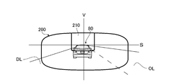
- FIG. 6 is a diagram showing an example of a light distribution pattern of light emitted when a preceding vehicle is detected by the detection device 20.
- S indicates a horizontal line
- V indicates a vertical line passing through the center of the vehicle 100 in the left-right direction
- the light distribution pattern 200 formed on the virtual vertical screen arranged 25 m ahead of the vehicle 100 is a thick line.
- the lane DL shown in FIG. 6 is a traveling lane
- the lane OL is an overtaking lane.
- the shape of the light distribution pattern 200 is the same as the shape of the high beam light distribution pattern PH shown in FIG. 5, but the dimming region 210 is formed in a part of the light distribution pattern.
- the total luminous flux amount of the light from the light emitting unit 10 irradiated to the dimming region 210 is the total luminous flux amount of the light emitted from the light emitting unit 10 irradiated to the region corresponding to the dimming region 210 in the high beam light distribution pattern PH. Fewer.
- the intensity of light in the dimming region 210 is lower than a predetermined reference intensity. In the present embodiment, the intensity of light in the dimming region 210 is substantially constant.
- the dimming region 210 may be a region that is not irradiated with light. Therefore, the dimming region 210 is a region in which the total luminous flux amount of the light from the light emitting unit 10 is reduced as compared with before the signal indicating another vehicle is input.
- the light intensity distribution in the region other than the dimming region 210 in the light distribution pattern 200 is substantially the same as the light intensity distribution in the region other than the region corresponding to the dimming region 210 in the light distribution pattern PH. Therefore, the region other than the dimming region 210 in the light distribution pattern 200 is a region in which the total luminous flux amount of the light from the light emitting unit 10 is not reduced, and is brighter than the dimming region 210.
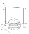
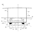
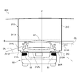
- FIG. 7 is an enlarged view of the dimming region 210 and its vicinity in the light distribution pattern 200.
- the dimming region 210 crosses a part of the preceding vehicle 80 in the left-right direction and overlaps the portion of the preceding vehicle 80 above the taillight 81.
- the dimming region 210 of the present embodiment has a first region 211 and a second region 212.
- the boundary between the first region 211 and the second region 212 is shown by a dotted line, and a pair of red light spots reflected in the captured image by the light from the taillight 81 are shown in black. There is.
- the second region 212 is an region that crosses the preceding vehicle 80 below the first region 211 and is connected to the lower edge 211U of the first region 211.
- the second region 212 extends in a strip shape in the left-right direction, and is located at the lowermost position of the dimming region 210.
- the lower edge 212U of the second region 212 extends substantially linearly in the left-right direction.
- the left edge 212L of the second region 212 is located on the right side of the left edge 211L of the first region 211, and is located between the left edge 211L of the first region and the preceding vehicle 80.
- the right edge 212R of the second region 212 is located on the left side of the right edge 211R of the first region 211, and is located between the right edge 211R of the first region 211 and the preceding vehicle 80. ing. Therefore, the width of the second region 212 in the left-right direction is smaller than the width of the first region 211 in the left-right direction. Further, in the present embodiment, the width in the left-right direction from the left edge 211L of the first region 211 to the preceding vehicle 80 is smaller than the width in the left-right direction from the right edge 211R of the first region 211 to the preceding vehicle 80.
- the width in the left-right direction from the left edge 211L of the first region 211 to the preceding vehicle 80 may be the same as the width in the left-right direction from the right edge 211R of the first region 211 to the preceding vehicle 80. It may be large.
- the width of the first region 211 and the width of the second region 212 change according to the distance from the vehicle 100 to the preceding vehicle 80, and the farther the distance from the vehicle 100 to the preceding vehicle 80, the wider these widths. It becomes smaller. Further, the positions of the first region 211 and the second region 212 change integrally according to the position of the preceding vehicle 80 with respect to the vehicle 100.
- a table stored in the memory ME is configured so that such a light distribution pattern 200 is formed.
- the positions of the side mirror 82 and the rear window 83, in which the driver visually recognizes the rear, differ depending on the type of vehicle.
- the side mirror 82 and the rear window 83 which are the visual recognition parts, are located in an area above the taillight 81 of the preceding vehicle 80, and are vertically located between the taillight 81 and the visual recognition part for visually recognizing the rear.
- a gap is formed in the direction.
- the detection device 20 can detect the position of the taillight 81 of the preceding vehicle 80. Therefore, even if the visible portion for visually recognizing the rear of the preceding vehicle 80 is not detected, the information regarding the electric power supplied to each light emitting element 13 for forming the light distribution pattern 200 having the dimming region 210 is preceded.
- the light distribution pattern 200 as described above can be formed by storing the light distribution pattern 200 in the memory ME in advance according to the position of the taillight 81 of the car 80.
- FIG. 8 is a diagram showing an example of a light distribution pattern of light emitted when an oncoming vehicle is detected by the detection device 20.
- S indicates a horizontal line
- V indicates a vertical line passing through the center of the vehicle 100 in the left-right direction
- the light distribution pattern 300 formed on the virtual vertical screen arranged 25 m ahead of the vehicle 100 is a thick line.
- the lane OL shown in FIG. 8 is an oncoming lane, and another road AL extending substantially perpendicular to the oncoming lane OL is connected to the oncoming lane OL. Therefore, the oncoming vehicle 90 traveling in the oncoming lane OL can turn left and travel on the road AL. When the oncoming vehicle 90 turns left, it is recognized that the oncoming vehicle 90 is turning to the right when viewed from the vehicle 100.
- the shape of the light distribution pattern 300 is the same as the shape of the high beam light distribution pattern PH shown in FIG. 5, but the dimming region 310 is formed in a part of the light distribution pattern.
- the total luminous flux amount of the light from the light emitting unit 10 irradiated to the dimming region 310 is the total luminous flux amount of the light emitted from the light emitting unit 10 irradiated to the region corresponding to the dimming region 310 in the high beam light distribution pattern PH. Fewer.
- the intensity of light in the dimming region 310 is lower than a predetermined reference intensity. In this embodiment, the intensity of light in the dimmed region is substantially constant.
- the dimming region 310 may be a region that is not irradiated with light. Therefore, the dimming region 310 is a region in which the total luminous flux amount of the light from the light emitting unit 10 is reduced as compared with before the signal indicating another vehicle is input.
- the light intensity distribution in the region other than the dimming region 310 of the light distribution pattern 300 is substantially the same as the light intensity distribution in the region other than the region corresponding to the dimming region 310 in the light distribution pattern PH. Therefore, the region other than the dimming region 310 in the light distribution pattern 300 is a region in which the total luminous flux amount of the light from the light emitting unit 10 is not reduced, and is brighter than the dimming region 210.
- FIG. 9 is an enlarged view of the dimming region 310 and its vicinity in the light distribution pattern 300.
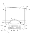
- the dimming region 310 crosses a part of the oncoming vehicle 90 detected by the detection device 20 in the left-right direction, and the portion of the oncoming vehicle 90 above the headlight 91. It overlaps with.
- the dimming region 310 of the present embodiment has a first region 311 and a second region 312.
- the boundary between the first region 311 and the second region 312 is shown by a dotted line, and a pair of white light spots reflected in the captured image by the light from the headlight 91 are shown by hatching. ing.
- the first region 311 is an region that crosses the oncoming vehicle 90 above the second region 312 and overlaps the entire front window 93 of the oncoming vehicle 90.
- the front window 93 is a visual recognition unit for the driver of the oncoming vehicle 90 to visually recognize the front outside the vehicle.
- the lower edge 311U of the first region 311 extends substantially linearly in the left-right direction.
- the second region 312 is an region that crosses the oncoming vehicle 90 below the first region 311 and is connected to the lower side of the first region 311.
- the second region 312 extends in a strip shape in the left-right direction, and is located at the lowermost position of the dimming region 310.
- the lower edge 312U of the second region 312 extends substantially linearly in the left-right direction.
- the left edge 312L of the second region 312 is located closer to the oncoming vehicle 90 than the left edge 311L of the first region 311 and the right edge 312R of the second region 312 is from the right edge 311R of the first region 311. Is also located on the side of the oncoming vehicle 90.
- the width of the second region 312 in the left-right direction is smaller than the width of the first region 311 in the left-right direction.
- the width in the left-right direction from the right edge 311R of the first region 311 to the oncoming vehicle 90 is larger than the width from the left edge 311L of the first region 311 to the oncoming vehicle 90.
- the width in the left-right direction from the edge 311R on the right side of the first region 311 to the oncoming vehicle 90 may be the same as or smaller than the width from the left edge 311L of the first region 311 to the oncoming vehicle 90. ..
- the width of the first region 311 and the width of the second region 312 change according to the distance from the vehicle 100 to the oncoming vehicle 90 detected by the detection device 20, and the distance from the vehicle 100 to the oncoming vehicle 90. The farther they are, the smaller these widths are. Further, the positions of the first region 211 and the second region 212 change integrally and their widths change according to the direction of the oncoming vehicle 90 with respect to the vehicle 100. In the present embodiment, a table stored in the memory ME is configured so that such a light distribution pattern 300 is formed. The shorter the distance from the vehicle 100 to the oncoming vehicle 90, the larger the width from the right edge 311R of the first region 311 to the oncoming vehicle 90 may be.
- the position of the front window 93, in which the driver visually recognizes the front differs depending on the type of vehicle.
- the front window 93 which is a visual recognition unit, is located in an area above the headlight 91 of the oncoming vehicle 90, and is vertically located between the headlight 91 and the visual recognition unit for visually recognizing the front.
- a gap is formed in the direction.
- the detection device 20 can detect the position of the headlight 91 of the oncoming vehicle 90. Therefore, even if the visible portion for visually recognizing the front of the oncoming vehicle 90 is not detected, the oncoming vehicle can provide information on the power supplied to each light emitting element 13 in order to form the light distribution pattern 200 having the dimming region 310.
- the light distribution pattern 300 as described above can be formed by storing the light distribution pattern 300 in the memory ME in advance according to the position of the headlight 91 of the 90.
- the region including the first regions 211 and 311 of the light distribution pattern that overlaps with all of the visibility units for the driver of the other vehicle to visually recognize the outside of the vehicle is the other vehicle.
- the light emitting unit 10 is controlled so as to be in the dimming regions 210 and 310 in which the total luminous flux amount of the light from the light emitting unit 10 is reduced as compared with before the signal shown is input.
- step SP15 and step SP16 for changing the light distribution pattern according to the turning notice of another vehicle will be described.
- steps SP15 and SP16 will be described by taking the case where another vehicle is the preceding vehicle as an example.
- Step SP15 This step is a step of determining whether or not another vehicle has issued a turning notice.
- FIG. 10 is a diagram showing how the right turn lamp of the preceding vehicle 80 blinks from the same viewpoint as in FIG. 7.
- the preceding vehicle 80 blinks the right turn lamp 84R in order to move to the overtaking lane OL.
- the driver of the preceding vehicle 80 blinks the right turn lamp 84R and issues a turning notice to the driver of the vehicle 100 or the like that the preceding vehicle 80 turns to the right.
- the light emitted from the right turn lamp 84R One orange light spot is projected at predetermined time intervals. In FIG.
- the detection unit of the detection device 20 outputs a signal indicating the blinking of the right turn lamp 84R of the preceding vehicle 80 to the determination unit 25.
- this signal is a signal indicating that the preceding vehicle 80 is scheduled to turn to the right when viewed from the vehicle 100.
- a signal indicating the preceding vehicle is input to the determination unit 25.
- the determination unit 25 determines that the right turn lamp of the preceding vehicle 80 is blinking, and outputs a signal indicating the blinking of the right turn lamp of the preceding vehicle 80 to the control unit CO.
- This signal is a signal indicating that the turning direction side of the preceding vehicle 80 is on the right side when viewed from the vehicle 100.
- the control unit CO further inputs a signal indicating the turning notice of the other vehicle in addition to the signal indicating the other vehicle, the control unit CO advances the control flow to step SP16.
- control unit CO advances the control flow to step SP17.
- Step SP16 This step is a step of emitting light that forms a light distribution pattern according to the turning notice.
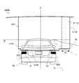
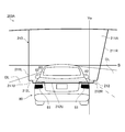
- FIG. 11 is a diagram showing a state in which the light distribution pattern shown in FIG. 7 has changed from the same viewpoint as in FIG.
- the light distribution pattern 200A shown in FIG. 11 is a light distribution pattern stored in the memory ME as one of the light distribution patterns corresponding to the turning notice, and the first region 211 of the dimming region 210 shown in FIG. 7 is
- the determination unit 25 includes a first region 211A that is wider to the right than before the determination in step 15.
- the second region 212 of the light distribution pattern 200A shown in FIG. 11 is the same as the second region 212 of the light distribution pattern 200 shown in FIG. 7.
- the control unit CO refers to the table stored in the memory ME and outputs a control signal for forming the light distribution pattern 200 to the power supply circuit 30. do. Then, a predetermined electric power is supplied to each light emitting element 13 by the operation of the driver based on the control. As a result, the light forming the light distribution pattern 200A is generated in the light emitting unit 10, and the light having the light distribution pattern 200A is emitted from the vehicle headlight 1. In this way, the first region 211 in the dimming region 210 is the vehicle after the signal indicating the other vehicle is input to the control unit CO and before the signal indicating the turning notice of the other vehicle is input to the control unit CO.
- the control unit CO returns the control flow to step SP11 without performing steps SP17 and 18 described later.
- steps SP15 and 16 the example in which the preceding vehicle 80 is scheduled to turn to the right has been described, but when the preceding vehicle 80 is scheduled to turn to the left, the preceding vehicle 80 is viewed from the vehicle 100.
- the light distribution pattern is changed so that the first region 211 spreads toward the left side of the visible portion of the above.
- steps SP15 and SP16 will be described by taking the case where another vehicle is an oncoming vehicle as an example.
- FIG. 12 is a view showing how the right turn lamp of the oncoming vehicle 90 blinks from the same viewpoint as in FIG.
- the oncoming vehicle 90 which is another vehicle, blinks the left turn lamps 94L and 95L in order to turn left on the road AL.
- the left turn lamp 94L is provided on a part of the left headlight 91 of the oncoming vehicle 90
- the left turn lamp 95L is provided on the cover of the left side mirror of the oncoming vehicle 90. ..
- the left turn lamps 94L and 95L blink in synchronization.
- the driver of the oncoming vehicle 90 blinks the left turn lamps 94L and 95L, and issues a turning notice to the driver of the vehicle 100 and the like that the oncoming vehicle 90 turns to the left.
- the oncoming vehicle 90 is scheduled to turn to the right.
- the left turn lamps 94L and 95L Two orange-based light spots due to the light emitted from the camera are projected at predetermined time intervals. In FIG. 12, white light spots are indicated by hatching, and orange light spots are indicated by black coating.
- the detection unit of the detection device 20 outputs a signal indicating the blinking of the left turn lamp of the oncoming vehicle 90 to the determination unit 25.
- this signal is a signal indicating that the oncoming vehicle 90 is scheduled to turn to the right when viewed from the vehicle 100.
- a signal that the other vehicle is an oncoming vehicle and a signal that the oncoming vehicle is in a state of satisfying a predetermined requirement are input to the determination unit 25.
- the determination unit 25 determines that the left turn lamp of the oncoming vehicle 90 is blinking, and outputs a signal indicating that the left turn lamp of the oncoming vehicle 90 is lit as a signal indicating a turning notice of another vehicle to the control unit CO. do.
- This signal is a signal indicating that the turning direction side of the oncoming vehicle 90 is on the right side when viewed from the vehicle 100.
- the control unit CO advances the control flow to step SP16.
- control unit CO advances the control flow to step SP17.
- FIG. 13 is a diagram showing a state in which the light distribution pattern shown in FIG. 9 has changed from the same viewpoint as in FIG.
- the light distribution pattern 300A shown in FIG. 13 is a light distribution pattern stored in the memory ME as one of the light distribution patterns corresponding to the turning notice, and the first region 311 of the dimming region 310 shown in FIG. 9 is on the right side. It contains a first region 311A that extends to.
- the second region 312 of the light distribution pattern 300 shown in FIG. 13 is the same as the second region 312 of the light distribution pattern 300 shown in FIG.
- the control unit CO refers to the table stored in the memory ME and outputs a control signal for forming the light distribution pattern 300A to the power supply circuit 30. do.
- a predetermined electric power is supplied to each light emitting element 13 by the operation of the driver based on the control signal.
- the light forming the light distribution pattern 300A is generated in the light emitting unit 10, and the light having the light distribution pattern 300A is emitted from the vehicle headlight 1.
- the first region 311 in the dimming region 310 is the vehicle after the signal indicating the other vehicle is input to the control unit CO and before the signal indicating the turning notice of the other vehicle is input to the control unit CO.
- the control unit CO When viewed from 100, it spreads toward the right side of the visible portion of the oncoming vehicle 90. In this case, the right side of the visible portion of the oncoming vehicle 90 when viewed from the vehicle 100 corresponds to the turning direction side indicated by the turning notice. Then, the control unit CO returns the control flow to step SP11 without performing steps SP17 and 18 described later.
- steps SP15 and 16 the example in which the oncoming vehicle 90 is scheduled to turn to the right when viewed from the vehicle 100 has been described, but when the oncoming vehicle 90 is scheduled to turn to the left when viewed from the vehicle 100,
- the light distribution pattern is changed so that the first region 311 expands toward the left side of the visible portion of the oncoming vehicle 90 when viewed from the vehicle 100.
- the control unit CO indicates the turning notice of the other vehicle after the signals indicating the other vehicle are input to the first regions 211 and 311 of the dimming regions 210 and 310.
- the light emitting unit 10 is controlled so that the light emitting unit 10 spreads toward the turning direction side as compared with before the signal is input.
- steps SP17 and step SP18 for changing the light distribution pattern according to the turning of another vehicle will be described.
- steps SP17 and 18 will be described by taking the case where another vehicle is the preceding vehicle as an example.
- Step SP17 This step is a step of determining whether or not another vehicle is turning.
- FIG. 14 is a diagram showing how the preceding vehicle 80 has started turning to the right when viewed from the vehicle 100, from the same viewpoint as in FIG. 7.
- step SP15 the determination unit 25 does not determine that the preceding vehicle 80 has issued a turn notice. Therefore, this step is executed. As shown in FIG. 14, immediately after the preceding vehicle 80 starts turning to the right, the light of the above-mentioned light distribution pattern 200 is emitted toward the preceding vehicle 80.
- FIG. 15 schematically shows a pair of red light spots in a captured image captured when a predetermined time has elapsed from the state of FIG. 14, together with a light distribution pattern 200.
- the taillight 81 in the state of FIG. 14 is shown by a broken line. As shown in FIG.
- the determination unit 25 determines that the preceding vehicle 80 is turning to the right. Then, the determination unit 25 inputs a signal indicating a right turn of the preceding vehicle 80 to the control unit CO. This signal is a signal indicating that the turning direction of the preceding vehicle 80 is on the right side when viewed from the vehicle 100. When this signal is input, the control unit CO advances the control flow to step SP18.
- control unit CO returns the control flow to step SP11.
- Step SP18 This step is a step of emitting a light distribution pattern according to the turning of another vehicle.
- FIG. 16 is a diagram showing a state in which the light distribution pattern shown in FIG. 14 has changed from the same viewpoint as in FIG. 7.
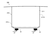
- the right edge 211R in the first region 211 of the light distribution pattern 200 before the change is shown by a broken line.
- the light distribution pattern before the change corresponds to the light distribution pattern immediately before step SP17.
- the light distribution pattern 200B shown in FIG. 16 is a light distribution pattern stored in the memory ME as one of the light distribution patterns corresponding to the turning, and the first region 211 in the dimming region 210 shown in FIG. 7 is determined.
- the unit 25 includes the first region 211B that has expanded to the right side as compared with before the determination of step SP17.
- the second region 212 of the light distribution pattern 200B is the same as the second region 212 of the light distribution pattern 200 shown in FIG. 7, and has not changed from the state of step SP14.
- the control unit CO refers to the table stored in the memory ME and outputs a control signal for forming the light distribution pattern 200B to the power supply circuit 30. Then, a predetermined electric power is supplied to each light emitting element 13 by the operation of the driver based on the control signal. As a result, the light forming the light distribution pattern 200B is generated in the light emitting unit 10, and the light having the light distribution pattern 200B is emitted from the vehicle headlight 1. In this way, the first region 211 in the dimming region 210 expands toward the right side of the visible portion of the preceding vehicle 80 when viewed from the vehicle 100 by the length d2 as compared with before the determination unit 25 determines the step SP17. In the present embodiment, this length d2 is a length larger than the above-mentioned predetermined length d1.
- control unit CO returns the control flow to step SP11.
- steps SP17 and 18 will be described by taking the case where another vehicle is an oncoming vehicle as an example.
- Step SP17 For example, consider a case where an oncoming vehicle 90, which is another vehicle, turns to the left when viewed from the vehicle 100.
- FIG. 17 is a diagram showing a state in which the oncoming vehicle 90 is traveling in the oncoming lane OL that curves to the left when viewed from the vehicle 100 from the same viewpoint as in FIG. That is, in the state of FIG. 17, the oncoming vehicle 90 is turning to the right when viewed from the oncoming vehicle 90.
- the turn lamp is not blinked. Therefore, the oncoming vehicle 90 does not blink the turn lamp, and in step SP15, the determination unit 25 does not determine that the preceding vehicle 80 has issued a turn notice. Therefore, this step is executed.
- the light of the above-mentioned light distribution pattern 300 is emitted in the state of FIG.
- FIG. 17 schematically shows a pair of white light spots in a captured image captured when a predetermined time has elapsed from the state of FIG. 17, together with a light distribution pattern 300.
- the headlight 91 in the state of FIG. 17 is shown by a broken line. As shown in FIG.
- the pair of white light spots are shifted to the left.
- the determination unit 25 determines that the oncoming vehicle 90 is turning to the right. Then, the determination unit 25 inputs a signal indicating a right turn of the oncoming vehicle 90 to the control unit CO.
- This signal is a signal indicating that the turning direction of the oncoming vehicle 90 is on the left side when viewed from the vehicle 100.
- the control unit CO advances the control flow to step SP18.
- control unit CO returns the control flow to step SP11.
- FIG. 19 is a diagram showing a state in which the light distribution pattern shown in FIG. 17 has changed from the same viewpoint as in FIG.
- the left edge 311L in the first region 311 of the light distribution pattern 300 before the change is shown by a broken line.
- the light distribution pattern before the change corresponds to the light distribution pattern immediately before step SP17.
- the light distribution pattern 300B shown in FIG. 19 is a light distribution pattern stored in the memory ME as one of the light distribution patterns corresponding to the turning, and the first region 311 of the dimming region 310 shown in FIG. 9 is determined.
- the unit 25 includes a first region 311B that is wider to the left side than before the determination of step SP17.
- the second region 312 of the light distribution pattern 300B is the same as the second region 312 of the light distribution pattern 300 shown in FIG. 9, and has not changed from the state of step SP14.
- the control unit CO refers to the table stored in the memory ME and transmits a control signal for forming the light distribution pattern 300B to the power supply circuit 30. Output to. Then, a predetermined electric power is supplied to each light emitting element 13 by the operation of the driver based on the control signal. As a result, the light forming the light distribution pattern 300B is generated in the light emitting unit 10, and the light having the light distribution pattern 300B is emitted from the vehicle headlight 1.
- the first region 311 in the dimming region 310 expands toward the left side of the visible portion of the oncoming vehicle 90 when viewed from the vehicle 100 by the length d2 as compared with before the determination unit 25 determines the step SP17.
- the length d2 is set to be larger than the predetermined length d1 described above.
- control unit CO returns the control flow to step SP11.
- steps SP17 and 18 the example in which the oncoming vehicle 90 is turning to the right has been described, but when the oncoming vehicle 90 is turning to the left, the right side of the visual recognition portion of the oncoming vehicle 90 is described.
- the light distribution pattern is changed so that the first region 311 expands toward.
- step SP17 when the determination unit 25 determines in step SP15 that the other vehicle has not issued a turn notice, in step SP17, the other vehicle turns based on the information from the detection device 20. Further determine whether or not it is done. Then, in step 18, when it is determined that the other vehicle is turning in this step 17, the first regions 211 and 311 of the dimming regions 210 and 310 are on the turning direction side as compared with before this determination.
- the control unit CO controls the light emitting unit 10 so as to spread.
- Step SP19 In this step, no signal is input from the light switch 35 to the control unit CO. Therefore, the light switch 35 is in the off state.
- the control unit CO outputs a predetermined signal to the power supply circuit 30, stops the supply of electric power to the respective light emitting elements 13 to the power supply circuit 30, makes the light from the vehicle headlight 1 non-emission, and controls. The flow is returned to step SP11.
- the light distribution pattern of the light emitted from the vehicle headlight 1 is changed when the preceding vehicle 80 or the oncoming vehicle 90 blinks the turn lamp to give a turning notice or when the vehicle is turning.
- at least one of the turning notice and the turning motion of the other vehicle is also referred to as a turning motion.
- the control flow of the control unit CO is not limited to the control flow shown in FIG.
- the determination unit 25 may determine whether or not another vehicle is turning in step SP15, and may determine whether or not another vehicle is issuing a turn notice in step SP17.
- the determination unit 25 determines whether or not another vehicle has issued a turning notice.
- the determination unit 25 may simultaneously determine whether or not the other vehicle has issued a turning notice and whether or not the other vehicle is turning. good.
- steps SP15 to 18 can be considered as a control flow for determining whether or not another vehicle is performing a turning motion that is at least one of turning notice and turning.
- the vehicle headlight system 2 of the present embodiment includes a detection device 20 for detecting other vehicles 80 and 90, and a vehicle headlight 1. Further, the vehicle headlight 1 determines information from the light emitting unit 10 and the detection device 20 that emit light having a light distribution pattern that can be changed toward other vehicles 80 and 90 located in front of the vehicle 100.
- a determination unit 25 for generating a signal indicating the other vehicles 80 and 90 and a signal indicating the turning operation of the other vehicles 80 and 90, and a control unit CO are provided.
- the control unit CO has a light distribution pattern in which the region including the first regions 211 and 311 that overlap all the visible parts of the other vehicles 80 and 90 is the other vehicle 80.
- the light emitting unit 10 is controlled so as to be in the dimming regions 210 and 310 in which the total luminous flux amount of the light from the light emitting unit 10 is reduced as compared with before the signal indicating, 90 is input, and the other vehicles 80 and 90 are shown.
- a signal indicating the turning operation of the other vehicles 80 and 90 is further input in addition to the signal, after the signal indicating the other vehicles 80 and 90 is input to the first regions 211 and 311 of the dimming regions 210 and 310.
- the light emitting unit 10 is controlled so as to spread toward the turning direction side of the other vehicles 80 and 90 as compared with before the signal indicating the turning operation of the other vehicles 80 and 90 is input.
- the dimming regions 210 and 310 formed by the vehicle headlight 1 of the present embodiment have second regions 212 and 312 located below the first regions 211 and 311. For this reason, the width of the dimming region in the left-right direction is narrower below the visible portion of the other vehicles 80 and 90, and the ratio of the bright region to the light distribution pattern is large. Therefore, the forward visibility of the vehicle 100, which is the own vehicle, can be improved. Further, the region below the visible portion of the other vehicles 80 and 90 tends not to touch the line of sight of the driver of the other vehicle. Therefore, even if the second regions 212 and 312 are formed in this way, the dazzling of the drivers of the other vehicles 80 and 90 can be suppressed.
- the vehicle headlight 1 when the other vehicle turns, the dazzling of the driver of the other vehicle can be suppressed and the deterioration of the front visibility of the own vehicle can be suppressed.
- the dimming regions 210 and 310 of the present embodiment are irradiated with a certain amount of light, the dimming regions 210 and 310 have a certain degree of brightness. Therefore, as compared with the case where the dimming areas 210 and 310 are not irradiated with light, the front visibility of the driver of the own vehicle 100 is improved while suppressing the dazzling of the drivers of the other vehicles 80 and 90. Can be done. On the other hand, when the dimming regions 210 and 310 are not irradiated with light, the dazzling of the drivers of the other vehicles 80 and 90 can be further suppressed.
- the length d2 at which the dimming region is expanded when it is determined that the other vehicle is turning is the criterion for determining that the other vehicle is turning. It is larger than the length d1 of the deviation of the pair of light spots in the left-right direction.
- the determination unit 25 of the present embodiment determines the distances to the other vehicles 80 and 90 based on the information from the detection device 20, and controls a signal indicating the other vehicle when the distance is equal to or less than a predetermined distance.
- Output to CO In general, dazzling to other vehicles is more likely to occur as the distance to other vehicles is shorter. Therefore, by inputting a signal indicating another vehicle to the control unit CO when the distance is less than a predetermined distance, dazzling to the other vehicle can be effectively suppressed. Further, when the distance to another vehicle is larger than a predetermined distance, the dimming areas 210 and 310 do not widen, so that the visibility of the own vehicle can be improved while suppressing the dazzling of the other vehicle.
- the dimming regions 210 and 310 expand to the turning direction side of the other vehicles 80 and 90.
- the left edge of the second region is located to the right of the left edge of the first region and the right edge of the second region is located to the left of the right edge of the first region.
- the entire dimming areas 210 and 310 may be extended to the turning direction side of the other vehicles 80 and 90. In short, at least the first region may be widened to the side where the other vehicles 80 and 90 turn.
- FIG. 21 is a diagram showing the light distribution pattern in the second embodiment from the same viewpoint as in FIG.
- FIG. 22 is a diagram showing a state in which the light distribution pattern shown in FIG. 21 has changed.
- the same or equivalent components as those in the first embodiment are designated by the same reference numerals and duplicated description will be omitted unless otherwise specified.
- the shape and light intensity distribution of the light distribution pattern 200 in the present embodiment, and the shape and light intensity distribution of the dimming region 210 in the present embodiment are the same as those of the light distribution pattern 200 and the dimming region 210 in the first embodiment. The same is true. However, as shown in FIG. 21, the regions other than the second region 212 in the light distribution pattern 200 of the present embodiment are divided into the first region 211 and the third region 213. In this respect, the light distribution pattern 200 of the present embodiment is different from the light distribution pattern 200 of the first embodiment.
- the first region 211 and the third region 213 of the present embodiment are separated from each other with reference to a line extending in the left-right direction slightly above the roof panel 87 of the preceding vehicle 80.
- the line is shown by a broken line in FIG. 21, which corresponds to the upper edge 211J of the first region 211.
- the first region 211 is an region that overlaps with the entire side mirror 82 and the rear window 83, which are the visual recognition portions of the preceding vehicle 80.
- the third region 213 is connected to the upper edge 211J of the first region 211 and is located at the uppermost portion of the dimming region 210.
- the control unit CO of the present embodiment is, for example, after the signal indicating another vehicle is input when it is determined that the preceding vehicle 80 is issuing a turn notice to the right.
- the first region 211 spreads to the right side on the turning direction side of the preceding vehicle 80, and the right edge on the turning direction side of the third region 213 is the first. 2
- the light emitting unit 10 is controlled so as not to move from the position before the determination.
- the light distribution pattern 200A after the change of the present embodiment becomes a light distribution pattern having the first region 211A in which the first region 211 extends to the right side.
- the third region located above the first region does not spread to the turning direction side, so that the third region is combined with the first region.
- the proportion of bright areas in the light distribution pattern is larger than when it is widened. Therefore, it is possible to suppress a decrease in the front visibility of the own vehicle. Further, as described above, since the first region extends to the side where the other vehicle issues a turning notice, it is possible to prevent the driver of the other vehicle from being dazzled.
- the edge on the turning direction side of the third region 213 is the edge on the turning direction side of the first region.
- the light emitting unit 10 may be controlled so as to be located closer to the other vehicle. Even in this case, the spread of the third region 213 toward the turning direction is suppressed. As a result, the proportion of the bright region in the light distribution pattern is larger than that in the case where the spread of the third region 213 in the turning direction side is equivalent to the spread of the first region 211 and the turning direction side. Therefore, it is possible to suppress a decrease in the front visibility of the own vehicle.
- the position of the upper edge of the first region in the vertical direction is not particularly limited as long as it does not prevent the first region from overlapping with the entire visual recognition portion of the other vehicle.
- the position is above the roof panel of another vehicle and below the center of the upper edge of the light distribution pattern and the roof panel.
- the visible portion of the other vehicle is generally located below the roof panel of the other vehicle. Therefore, if the upper edge of the first region is located above the roof panel, the entire visible portion can more reliably overlap the first region. Further, if the upper edge of the first region is located below the center between the upper edge of the light distribution pattern and the roof panel, it can be suppressed that the area of the third region becomes too small. .. Therefore, when another vehicle issues a turning notice, it is possible to further suppress the unnecessarily expanding of the dimming area, and it is possible to further suppress the deterioration of the front visibility of the own vehicle.
- the present embodiment can also be applied to the case where another vehicle is turning. That is, the present embodiment can be applied to the case where another vehicle is performing a turning operation that is at least one of a turning notice and a turning.
- FIG. 23 is a diagram showing a state in which the light distribution pattern in the present embodiment has changed.
- the same or equivalent components as those in the first embodiment are designated by the same reference numerals and duplicated description will be omitted unless otherwise specified.
- the preceding vehicle 80 has issued a turn notice to the right.
- the turning direction side of the preceding vehicle 80 is on the right side when viewed from the own vehicle, and the control unit CO is on the right side of the preceding vehicle 80 as the right edge 211R of the first region 211 of the dimming region 210 goes upward.
- the light emitting unit 10 is controlled so as to be away from the vertical line Va passing through the end portion of the light emitting unit 10.
- the first region 211 expands to the turning direction side of the preceding vehicle 80. Therefore, when the preceding vehicle 80 turns, the dazzling of the driver of the preceding vehicle 80 can be suppressed.
- the dimming region on the turning direction side is changed so as to move away from the vertical line Va as it goes upward, the dimming region is expanded toward the turning direction while the edge is parallel to the vertical line Va.
- the ratio of the bright region to the changed light distribution pattern can be increased as compared with the above. Therefore, it is possible to further suppress the deterioration of the front visibility of the own vehicle.
- the control unit CO when the signal indicating the turning notice of the other vehicles 80 and 90 is input, the control unit CO is the other vehicle as the edges of the first regions 211 and 311 on the turning direction side go upward.
- the light emitting unit 10 is controlled so as to be away from the vertical line passing through the end portion of the 80 and 90 on the turning direction side.
- FIG. 23 shows an example in which the right edge 211R of the first region 211 is inclined so as to be separated from the vertical line Va as it goes upward, but it is on the turning direction side of the first regions 211 and 311.
- the edge does not necessarily have to be inclined, and may be stepped, for example, as long as the edge moves upward and away from the vertical line passing through the end of the other vehicles 80, 90 on the turning direction side.
- the present embodiment can also be applied to the case where another vehicle is turning. That is, the present embodiment can be applied to the case where another vehicle is performing a turning operation that is at least one of a turning notice and a turning.
- a vehicle headlight that changes the high beam light distribution pattern according to another vehicle detected by the detection device 20 has been described as an example.
- the vehicle headlight may change the light distribution pattern of the light emitted according to the other vehicle detected by the detection device 20.
- the vehicle headlight may change the low beam light distribution pattern according to another vehicle detected by the detection device 20.
- the light emitting unit 10 having the light distribution pattern forming unit 12 which is a so-called LED array has been described as an example.
- the light emitting unit 10 is not particularly limited as long as the light distribution pattern of the emitted light can be changed.
- the light emitting unit 10 is configured to form a predetermined light distribution pattern by scanning the light emitted from the light source using a reflector such as a rotating reflector, MEMS (Micro Electro Mechanical Systems), and a galvano mirror. There may be.
- the light distribution pattern of the emitted light can be changed by adjusting the inclination of the reflector or adjusting the light emitted from the light source.
- the light emitting unit 10 may be configured to form a predetermined light distribution pattern by diffracting the light emitted from the light source using LCOS (Liquid Crystal On Silicon).
- LCOS Liquid Crystal On Silicon
- the light distribution pattern of the emitted light can be changed by adjusting the orientation of the liquid crystal display in the LCOS.
- the light intensity distribution in the regions other than the dimming regions 210 and 310 of the light distribution patterns 200 and 300 is the region other than the regions corresponding to the dimming regions 210 and 310 of the light distribution pattern PH.
- the example which is almost the same as the light intensity distribution in is described, it is not limited to this. However, from the viewpoint of suppressing the driver of the vehicle 100 from feeling uncomfortable, it is preferable that the light intensity distribution in the regions other than the dimming regions 210 and 310 does not change.
- the light intensity in the dimming regions 210 and 310 may change depending on, for example, the distance from the vehicle 100 to another vehicle.
- the shape of the light distribution pattern described in the above embodiment is an example and can be changed as appropriate.
- the width of each of the above-mentioned first region, second region, and third region in the left-right direction does not have to be constant along the up-down direction.
- the detection device 20 detects the preceding vehicle 80 based on the light from the taillight 81 of the preceding vehicle 80, and detects the oncoming vehicle 90 based on the light from the headlight 91 of the oncoming vehicle 90.
- the configuration of the detection device 20 is not limited to this.
- the detection device 20 may detect the side mirror 82, the rear window 83, etc., which are the visual recognition parts of the preceding vehicle 80, or the front window 93, which is the visual recognition part of the oncoming vehicle 90.
- the control unit CO may control the pair of light emitting units 10 based on the information of these visual recognition units detected by the detection device 20.
- turn notice is not limited to this.
- communication information between vehicles in the automatic driving mode road information obtained from navigation, road surface drawing drawn by another vehicle, and the like can be mentioned.
- the present invention is not limited to this. For example, it may be determined whether or not the other vehicle is turning based on the communication information between the vehicles in the automatic driving mode, the road information obtained from the navigation, the movement of the road surface drawing drawn by the other vehicle, and the like.
- a signal indicating another vehicle is input from the determination unit 25 to the control unit CO.
- a signal indicating another vehicle may be input from the detection device 20 to the control unit CO.
- the signal indicating the other vehicle is input to the control unit CO without the determination by the determination unit 25, the signal indicating the turning operation of the other vehicle is input to the control unit CO to reduce the distance to the other vehicle.
- the first region can be expanded toward the turning direction of another vehicle without depending on the vehicle.
- a vehicle headlight and a vehicle headlight that can suppress the dazzling of the driver of the other vehicle when the other vehicle turns and can suppress the deterioration of the front visibility of the own vehicle.
- a vehicle headlight system is provided and can be used in fields such as vehicle headlights for automobiles and the like.
Landscapes
- Engineering & Computer Science (AREA)
- Mechanical Engineering (AREA)
- Lighting Device Outwards From Vehicle And Optical Signal (AREA)
Abstract
車両用前照灯(1)は、発光ユニット(10)と、判定部(25)と、制御部(CO)と、を備える。制御部(CO)は、他車両を示す信号が入力する場合において、配光パターンのうち第1領域(211,311)を含む領域が、減光領域(210,310)となるように発光ユニット(10)を制御し、他車両を示す信号に加えて前記他車両の旋回動作を示す信号がさらに入力する場合において、減光領域(210,310)のうち少なくとも第1領域(211,311)が、他車両(80,90)を示す信号が入力した後であって他車両(80,90)の旋回動作を示す信号が入力する前に比べて他車両(80,890)の旋回方向側に広がるように発光ユニット(10)を制御する。また、減光領域(210,310)は第1領域(211,311)の下方側の縁に接続する第2領域(212,312)を含む。
Description
本発明は、車両用前照灯及び当該車両用前照灯を備える車両用前照灯システムに関する。
車両の前方に位置する他の車両を検出する検出装置からの情報に基づいて、出射する光の配光パターンを変化させる車両用前照灯が知られている。下記特許文献1には、このような車両用前照灯が記載されており、この車両用前照灯は、出射する光の配光パターンを変更可能な発光ユニットと、車両の前方に位置する他車両を検出する検出装置と、他車両への光の照射を抑制しつつ、他車両の周囲に光が照射されるように当該車両用前照灯の照射範囲を制御する制御部と、を備える。この制御部は、他車両の左右方向の位置に応じて、光の照射が抑制される領域の左右方向の幅が変化するように灯具を制御する。このような構成により、車両に対する他車両の位置に応じて他車両と照射範囲との間に適切な隙間を確保することが可能となり、他車両の運転者が眩惑することを抑制できるとされる。
しかし、上記特許文献1では、他車両が旋回する際における当該他車両の運転者の眩惑について考慮されていない。また、上記のように光の照射が抑制される領域を配光パターンに形成する場合、配光パターンの一部の領域が配光パターンの他の領域に比べて暗くなるため、自車両の前方視認性が低下する傾向がある。
そこで、本発明は、他車両が旋回する際に当該他車両の運転者の眩惑を抑制し得るとともに自車両の前方視認性の低下を抑制し得る車両用前照灯及び当該車両用前照灯を備える車両用前照灯システムを提供することを目的とする。
上記目的の達成のため、本発明は、車両に搭載される車両用前照灯であって、前記車両の前方に位置する他車両に向かって、変更可能な配光パターンの光を出射する発光ユニットと、前記他車両を検出する検出装置からの情報を判定して、旋回予告及び旋回の少なくとも一方である前記他車両の旋回動作を示す信号を生成する判定部と、前記検出装置で検出された前記他車両を示す信号及び前記他車両の旋回動作を示す信号が入力する制御部と、を備え、前記制御部は、前記他車両を示す信号が入力する場合において、前記配光パターンのうち少なくとも前記他車両の運転者が車外を視認するための視認部の全てに重なる第1領域を含む領域が、前記他車両を示す信号が入力する前に比べて前記発光ユニットからの光の全光束量が減じられた減光領域となるように前記発光ユニットを制御し、前記他車両を示す信号に加えて前記他車両の旋回動作を示す信号がさらに入力する場合において、前記減光領域のうち少なくとも前記第1領域が、前記他車両を示す信号が入力した後であって前記他車両の旋回動作を示す信号が入力する前に比べて、前記他車両の旋回方向側に広がるように前記発光ユニットを制御し、前記減光領域は、前記第1領域の下方側の縁に接続する第2領域を含み、前記第2領域の左側の縁は前記第1領域の左側の縁よりも右側に位置するとともに、前記第2領域の右側の縁は前記第1領域の右側の縁よりも左側に位置することを特徴とするものである。
ここで、旋回予告とは、例えば、他車両のターンランプが点滅している状態であってもよい。また、旋回方向側とは、自車両から見た場合における他車両の旋回する予定である側又は旋回している側を意味する。例えば、他車両が先行車である場合において、当該他車両の右ターンランプが点滅する場合或いは他車両が右に旋回している場合、すなわち、他車両が右側への旋回動作をしている場合、旋回方向側は自車両から見て右側となる。一方、他車両が対向車である場合において、当該他車両の左ターンランプが点滅する場合或いは左に旋回している場合、すなわち、他車両が左側への旋回動作をしている場合、旋回方向側は自車両から見て右側となる。また、他車両の運転者が車外を視認するための視認部としては、他車両が対向車の場合には例えばフロントウインド等を挙げることができ、他車両が先行車の場合には例えばサイドミラー、リアウインド、車両の後方を撮像する撮像装置等を挙げることができる。
この車両用前照灯では、上述のように、他車両の旋回動作を示す信号が制御部に入力する場合に、上記減光領域のうち少なくとも第1領域が、他車両を示す信号が入力した後であって他車両の旋回予告を示す信号が入力する前に比べて旋回方向側に広がる。このため、配光パターンのうち他車両の運転者の視線が移動する領域が配光パターンの他の領域に比べて暗くなり得る。したがって、この車両用前照灯によれば、他車両が旋回する際に当該他車両の運転者の眩惑を抑制し得る。
また、この車両用前照灯では、上述のように、前記減光領域は、前記第1領域の下方側の縁に接続する第2領域を含み、前記第2領域の左側の縁は前記第1領域の左側の縁よりも右側に位置するとともに、前記第2領域の右側の縁は前記第1領域の右側の縁よりも左側に位置する。このような構成によれば、他車両の視認部より下方において減光領域の左右方向における幅が狭くなるため、配光パターンに占める明るい領域の割合を大きくすることができる。したがって、自車両の前方視認性が向上し得る。また、他車両の視認部よりも下方側の領域は、他車両の運転者の視線に触れない傾向が強い。したがって、このように第2領域を形成しても、他車両の運転者の眩惑を抑制し得る。
このように、この車両用前照灯によれば、他車両が旋回する際に当該他車両の運転者の眩惑を抑制し得るとともに自車両における前方視認性の低下を抑制し得る。
また、前記減光領域は、前記第1領域の上方側の縁に接続する第3領域を含み、前記制御部は、前記他車両を示す信号に加えて前記他車両の旋回動作を示す信号がさらに入力する場合において、前記第3領域の前記旋回方向側の縁が前記第1領域の前記旋回方向側の縁よりも前記他車両側に位置するように前記発光ユニットを制御してもよい。
この場合、他車両が旋回動作をしている場合において、第1領域の上方側に位置する第3領域の旋回方向側への広がりが抑制される。その結果、第3領域の旋回方向側への広がりが第1領域と旋回方向側への広がりと同等である場合に比べて、配光パターンに占める明るい領域の割合が大きくなる。このため、自車両の前方視認性の低下を抑制することができる。
上記減光領域に上記第3領域が含まれる場合、前記制御部は、前記他車両を示す信号に加えて前記他車両の旋回動作を示す信号がさらに入力する場合において、前記第3領域の前記旋回方向側の縁が前記他車両の旋回動作を示す信号が入力する前における位置から移動しないように前記発光ユニットを制御することが好ましい。
この場合、他車両が旋回動作をしている場合において、第1領域の上方側に位置する第3領域の旋回方向側への広がりがより抑制されるため、配光パターンに占める明るい領域の割合がより大きくなる。このため、自車両の前方視認性の低下をより抑制することができる。
また、上記減光領域に上記第3領域が含まれる場合、前記第1領域の上方側の縁の上下方向における位置は、前記他車両のルーフパネルよりも上方側、かつ、前記配光パターンの上方側の縁と前記ルーフパネルとの間の中央よりも下方側の位置であることが好ましい。
他車両の視認部は、概ね他車両のルーフパネルの下方側に存在する。このため、第1領域の上方側の縁がルーフパネルよりも上側に位置すれば、視認部の全体がより確実に第1領域に重なり得る。また、第1領域の上方の縁が配光パターンの上方側の縁とルーフパネルとの間の中央よりも下方側の位置にあれば、第3領域の面積が小さくなり過ぎることが抑制され得る。このため、他車両が旋回予告を発している場合に、減光領域が不必要に拡大することがより抑制され、自車両の前方視認性の低下をより抑制することができる。
また、前記制御部は、前記他車両を示す信号に加えて前記他車両の旋回動作を示す信号がさらに入力する場合において、前記減光領域のうち少なくとも前記第1領域の前記旋回方向側の縁が、上方に行くに従って前記他車両の前記旋回方向側の端部を通る鉛直線から離れるように前記発光ユニットを制御してもよい。
このような構成により、他車両が旋回動作をする際に減光領域の第1領域が他車両が旋回する側に広がる。このため、他車両が旋回する際に当該他車両の運転者の眩惑を抑制し得る。また、この場合、減光領域の旋回方向側の縁が上記鉛直線と平行なまま減光領域を広げる場合に比べて、変化後の配光パターンに占める明るい領域の割合を大きくし得る。したがって、自車両の前方視認性の低下をより抑制することができる。
また、前記判定部は、前記検出装置からの情報に基づいて前記他車両までの距離を判定し、当該距離が所定の距離以下の場合に前記他車両を示す信号を前記制御部に出力してもよい。
一般的に、他車両に対する眩惑は他車両までの距離が近い程生じ易くなる。このため、所定の距離以下の場合に他車両を示す信号が制御部に入力するようにすることで、他車両に対する眩惑を効果的に抑制することができる。また、他車両までの距離が所定の距離より大きい場合には減光領域が広がらないため、他車両の眩惑を抑制しつつ自車両の視認性を高めることができる。
また、上記目的達成のため、本発明の車両用前照灯システムは、上記いずれかに記載の車両用前照灯と、前記他車両を検出する検出装置と、を備えることを特徴とするものである。
この車両用前照灯システムは、上記いずれかに記載の車両用前照灯を備えている。このため、この車両用前照灯によって、他車両が旋回する際に当該他車両の運転者の眩惑が抑制され得るとともに自車両における前方視認性の低下が抑制され得る。
以上のように、本発明によれば、他車両が旋回する際に当該他車両の運転者の眩惑を抑制し得るとともに自車両の前方視認性の低下を抑制し得る車両用前照灯及び当該車両用前照灯を備える車両用前照灯システムを提供できる。
以下、本発明に係る車両用前照灯を実施するための形態が添付図面とともに例示される。以下に例示する実施形態は、本発明の理解を容易にするためのものであり、本発明を限定して解釈するためのものではない。本発明は、その趣旨を逸脱することなく、以下の実施形態から変更、改良することができる。また、上記添付図面では、理解を容易にするために各部材の寸法が誇張して示されている場合がある。
(第1実施形態)
図1は、第1実施形態における車両用前照灯及び車両用前照灯システムを備える車両100を概念的に示す平面図である。図1に示すように、この車両100は車両用前照灯システム2を備えており、当該車両用前照灯システム2は、車両用前照灯1と、車両100の前方に位置する他車両を検出する検出装置20とを備える。
図1は、第1実施形態における車両用前照灯及び車両用前照灯システムを備える車両100を概念的に示す平面図である。図1に示すように、この車両100は車両用前照灯システム2を備えており、当該車両用前照灯システム2は、車両用前照灯1と、車両100の前方に位置する他車両を検出する検出装置20とを備える。
本実施形態の車両用前照灯1は車両としての自動車に搭載可能な前照灯である。この車両用前照灯1は、左右一対の発光ユニット10と、制御部COと、判定部25と、一対の電源回路30と、メモリMEと、を主な構成として備える。なお、本明細書において、特に明示のない限り、「右」とは自車両である車両100の運転者の視点における右側を意味し、「左」とは自車両である車両100の運転者の視点における左側を意味する。
本実施形態では、一対の発光ユニット10は、車両100の左右方向において互いに概ね対称な形状とされ、車両100の前方に位置する他車両に向かって、変更可能な配光パターンの光を出射する。また、一方の発光ユニット10の構成は、形状が概ね対称であることを除いて、他方の発光ユニット10の構成と同じとされる。このため、以下では、一方の発光ユニット10について説明し、他方の発光ユニット10についての説明は省略する。
図2は、図1に示す一方の発光ユニット10を概略的に示す側面図である。図2に示すように、発光ユニット10は、配光パターン形成部12と、投影レンズ15と、筐体16とを主な構成として備える。なお、図2において、筐体16は鉛直断面にて示されている。
筐体16は、ランプハウジング17、フロントカバー18及びバックカバー19を主な構成として備える。ランプハウジング17の前方は開口しており、当該開口を塞ぐようにフロントカバー18がランプハウジング17に固定されている。また、ランプハウジング17の後方には前方よりも小さな開口が形成されており、当該開口を塞ぐようにバックカバー19がランプハウジング17に固定されている。
ランプハウジング17と、当該ランプハウジング17の前方の開口を塞ぐフロントカバー18と、当該ランプハウジング17の後方の開口を塞ぐバックカバー19とによって形成される空間は灯室10Rであり、この灯室10R内に配光パターン形成部12及び投影レンズ15が収容されている
図3は、図2に示す配光パターン形成部12を概略的に示す正面図である。図2及び図3に示すように、本実施形態の配光パターン形成部12は、光を出射する複数の発光素子13と、複数の発光素子13が実装される回路基板14とを有する。複数の発光素子13は、マトリックス状に配置されて上下方向及び左右方向に列を形成し、前方に向かって光を出射する。本実施形態では、これら発光素子13はLED(Light Emitting Diode)とされ、配光パターン形成部12は所謂LEDアレイである。なお、発光素子13の数、発光素子13の列の数、それぞれの発光素子13の列における発光素子13の数、発光素子13が配列される方向、発光素子13の種類は特に限定されるものではない。
このような配光パターン形成部12は、光を出射させる発光素子13を選択することで所定の配光パターンを形成することができる。また、配光パターン形成部12は、それぞれの発光素子13から出射する光の強度を調節することで所定の配光パターンにおける光の強度分布を調節することができる。
投影レンズ15は、入射する光の発散角を調節するレンズである。投影レンズ15は、配光パターン形成部12よりも前方に配置され、配光パターン形成部12から出射する光が入射し、この光の発散角が投影レンズ15で調節される。本実施形態では、投影レンズ15は、入射面及び出射面が凸状に形成されたレンズとされ、投影レンズ15の後方焦点は、配光パターン形成部12におけるいずれかの発光素子13の光の出射面上またはその近傍に位置している。配光パターン形成部12から出射する光がこの投影レンズ15で発散角が調節され、フロントカバー18を介して発光ユニット10から車両100の前方へ向けて所定の配光パターンの光が出射する。
制御部COは、例えば、マイクロコントローラ、IC(Integrated Circuit)、LSI(Large-scale Integrated Circuit)、ASIC(Application Specific Integrated Circuit)などの集積回路やNC(Numerical Control)装置を用いることができる。また、制御部COは、NC装置を用いた場合、機械学習器を用いたものであってもよく、機械学習器を用いないものであってもよい。後述するように、制御部COは、一対の発光ユニット10を制御する。
制御部COには、車両100が備えるライトスイッチ35が接続されている。本実施形態のライトスイッチ35は、光の出射または非出射を選択するスイッチである。例えば、ライトスイッチ35は、ライトスイッチ35がオンの場合には制御部COに光の出射を示す信号を出力し、ライトスイッチ35がオフの場合には制御部COに信号を出力しない。
判定部25は、検出装置20からの情報に基づいて、当該検出装置20によって検出された他車両が所定の要件を満たす状態か否かを判定する。所定の要件として、例えば、他車両と車両100との間の距離が所定の距離以下であることが挙げられる。本実施形態では、この所定の距離は、例えば100mである。ただし、上記所定の距離は100mよりも大きくてもよい。判定部25は、この所定の要件を満たす場合に、他車両を示す信号を生成して、当該信号を制御部COに出力する。なお、本実施形態の判定部25は、他車両が所定の要件を満たす状態であるとともに検出装置20から他車両が先行車である信号が入力する場合には、他車両を示す信号としての先行車を示す信号、車両100から先行車までの距離に関する信号、車両100に対する先行車の位置の情報としての撮像画像における赤色系の一対の光点の位置を示す信号、及び先行車の右側又は左側のターンランプがしていることを示す信号を制御部COに出力する。また、本実施形態の判定部25は、他車両が所定の要件を満たす状態であるとともに検出装置20から他車両が対向車である信号が入力される場合には、他車両を示す信号としての対向車を示す信号、車両100から対向車までの距離、車両100に対する対向車の位置の情報としての撮像画像における白色系の一対の光点の位置を示す信号、及び対向車の右側又は左側のターンランプが点滅していることを示す信号を制御部COに出力する。一方、判定部25は、他車両が所定の要件を満たさない場合、及び検出装置20から判定部25に信号が入力されない場合には、制御部COに信号を出力しない。このため、判定部25による判定とは、このように検出装置20から入力される信号に応じて場合分けをして出力する信号を変化させることと理解できる。
一方の電源回路30は一方の発光ユニット10に対応し、他方の電源回路30は他方の発光ユニット10に対応している。それぞれの電源回路30は、ドライバを含んでおり、制御部COから信号が入力すると、このドライバによって配光パターン形成部12の各発光素子13に供給される電力が調整される。こうして、それぞれの発光素子13から出射する光の強度が調節される。なお、電源回路30のドライバは、PWM(Pulse Width Modulation)制御によってそれぞれの発光素子13に供給される電力を調整してもよい。この場合、デューティーサイクルを調節することによって、それぞれの発光素子13から出射する光の強度が調節される。
メモリMEは、情報を記憶し、当該記憶した情報を読み出し可能に構成される。メモリMEは、例えば非一過性(non-transitory)の記録媒体であり、RAM(Random Access Memory)やROM(Read Only Memory)等の半導体記録媒体が好適であるが、光学式記録媒体や磁気記録媒体等の任意の形式の記録媒体を包含し得る。なお、「非一過性」の記録媒体とは、一過性の伝搬信号(transitory, propagating signal)を除く全てのコンピュータ読み取り可能な記録媒体を含み、揮発性の記録媒体を除外するものではない。
メモリMEには、撮像装置によって撮像された複数の撮像画像が、各撮像画像の撮像された時点と対応付けられて記憶される。また、メモリMEには、発光ユニット10から出射する光によって形成される配光パターンに関する情報と検出装置20によって検出される他車両の情報とが関連付けられたテーブルが記憶される。発光ユニット10から出射する光によって形成される配光パターンに関する情報として、例えば、配光パターン形成部12の各発光素子13に供給される電力に関する情報等が挙げられる。この各発光素子13に供給される電力に関する情報としては、例えば、後述するハイビームの配光パターンを形成する際及び旋回予告に応じた配光パターンを形成する際のそれぞれにおける、各発光素子13に供給される電力に関する情報等が挙げられる。また、検出装置20によって検出される他車両の情報として、例えば、他車両が先行車であるか対向車であるかの情報、車両100から他車両までの距離に関する情報、車両100に対する他車両の位置に関する情報、及び他車両のターンランプが点滅しているか否かの情報等が挙げられる。車両100に対する他車両の位置に関する情報としては、撮像画像における一対の光点の位置の情報等が挙げられ、他車両のターンランプが点滅しているか否かの情報としては、撮像画像における少なくとも一つの橙色系の光点に関する情報等が挙げられる。
検出装置20は、上述のように、車両用前照灯1とともに車両用前照灯システム2を構成する。本実施形態では、検出装置20は、当該他車両が先行車であるか対向車であるかを、例えば後述するように検出する一対の光点の色に基づいて識別することができる。また、検出装置20は、他車両が車両100から見て右側又は左側に旋回する予定であるか否かを検出することができる。さらに、検出装置20は、他車両が車両100から見て右側又は左側に旋回しているか否かを検出することができる。検出装置20は、例えば、図示しないカメラや検出部等を備えてもよい。カメラは、車両100の前部に取り付けられ、所定の時間間隔、例えば1/30秒間隔で車両100の前方を撮影する。なお、このカメラとしては、例えば、CCD(Charged coupled device)カメラであってもよい。カメラによって撮影される撮像画像には、一対の発光ユニット10から出射する光が照射される領域の少なくとも一部が含まれる。検出部は、カメラによって撮影された撮像画像に基づいて、上記他車両の存在、車両100に対する当該他車両の位置を検出することができ、他車両が先行車であるか対向車であるかの識別をすることができる。また、検出部は、他車両が車両100から見て右側又は左側に旋回する予定であるか否か或いは旋回しているか否かを検出することができる。
例えば、検出部は、対向車の前照灯から出射される光に基づいて対向車の存在、車両100に対する当該対向車の位置を検出する。具体的には、検出部は、撮像画像中に、左右方向に所定の間隔をあけて位置する所定の輝度より高い輝度を有する白色系の一対の光点がある場合には、対向車が存在することを示す信号を判定部25に出力する。この場合、検出部は、撮像画像における白色系の一対の光点の位置、白色系の一対の光点間の距離等に基づいて、例えば、車両100から対向車までの距離を演算する。そして、検出部は、車両100に対する対向車の位置の情報としての撮像画像における白色系の一対の光点の位置を示す信号、及び演算した車両100から対向車までの距離を示す信号を判定部25に出力する。また、検出部は、撮像画像において、上記一対の光点の間の中央よりも右側に、所定の輝度よりも高い輝度の橙色系の光点が少なくとも一つ存在する場合には、対向車の右ターンランプが点滅していることを示す信号を判定部25に出力する。この右ターンランプが点滅していることを示す信号は、車両100から見て他車両が左側に旋回する予定であることを示す信号であり、他車両の旋回予告が示す旋回方向側が左側であることを示す信号である。また、検出部は、撮像画像において、上記一対の光点の間の中央よりも左側に、所定の輝度よりも高い輝度の少なくとも一つの橙色系の光点が所定の時間間隔で点滅すると判定する場合には、対向車の左ターンランプが点滅していることを示す信号を判定部25に出力する。この対向車の左ターンランプが点滅していることを示す信号は、車両100から見て他車両が右側に旋回する予定であることを示す信号であり、他車両の旋回方向側が右側であることを示す信号である。
さらに、検出部は、所定の時間内に撮像された複数の撮像画像のうち最も先に撮像された撮像画像と、最も後に撮像された撮像画像とを対比して、後に撮像された撮像画像中の白色系の一対の光点の左右方向における位置が、先に撮像された撮像画像中の白色系の一対の光点の左右方向の位置に比べて左側又は右側に所定の長さ以上ずれている場合には、対向車が左側又は右側に旋回していると判定する。こうして、検出部は、対向車が旋回していることを示す信号を判定部25に出力する。例えば、対向車が左側に旋回している場合、自車両である車両100から見ると対向車は右側に旋回している。車両100によって撮像される上記一対の光点の位置は、所定の時間内において最も先に撮像された上記一対の光点の位置から右側にずれる。したがって、検出部は、この対比する2つの撮像画像における上記一対の光点の右側へのずれが所定の長さ以上である場合には、対向車の左旋回を示す信号を判定部25に出力する。対向車の左旋回を示す信号は、車両100から見て対向車が右側に旋回していることを示す信号であり、対向車の旋回方向側が右側であることを示す信号である。
また、検出部は、先行車の尾灯から出射される光に基づいて先行車の存在、車両100に対する当該先行車の位置を検出する。具体的には、検出部は、撮像画像に左右方向に所定の間隔をあけて位置する所定の輝度より高い輝度を有する赤色系の一対の光点がある場合には、先行車が存在することを示す信号を判定部25に出力する。この場合、検出部は、赤色系の一対の光点の位置、赤色系の一対の光点間の距離等に基づいて、例えば、車両100から先行車までの距離を演算する。そして、検出部は、車両100に対する先行車の位置の情報としての撮像画像における赤色の一対の光点の位置を示す信号、及び演算した車両100から先行車までの距離を示す信号を判定部25に出力する。また、検出部は、撮像画像において、上記一対の光点の間の中央よりも右側に、所定の輝度よりも高い輝度の少なくとも一つの橙色系の光点が所定の時間間隔で点滅すると判定する場合には、先行車の右ターンランプが点滅していることを示す信号を判定部25に出力する。この先行車の右ターンランプが点滅していることを示す信号は、他車両が車両100から見て右側に旋回する予定であることを示す信号であり、他車両の旋回予告が示す旋回方向側が右側であることを示す信号である。また、検出部は、上記一対の光点の間の中央よりも左側に、所定の輝度よりも高い輝度の少なくとも一つの橙色系の光点が所定の時間間隔で点滅すると判定する場合には、先行車の左ターンランプが点滅していることを示す信号を判定部25に出力する。この先行車の左ターンランプが点滅していることを示す信号は、他車両が車両100から見て左側に旋回する予定であることを示す信号であり、他車両の旋回予告が示す旋回方向側が左側であることを示す信号である。
さらに、検出部は、所定の時間内に撮像された複数の撮像画像のうち最も先に撮像された撮像画像と、最も後に撮像された撮像画像とを対比して、後に撮像された撮像画像中の赤色系の一対の光点の左右方向における位置が、先に撮像された撮像画像における赤色系の一対の光点の左右方向の位置に比べて左側又は右側に所定の長さ以上ずれている場合には、先行車が左側又は右側に旋回していると判定する。こうして、先行車が旋回していることを示す信号を判定部25に出力する。例えば、先行車が右側に旋回している場合、自車両である車両100から見ると先行車は右側に旋回している。車両100によって撮像される上記一対の光点の位置は、所定の時間内において最も先に撮像された上記一対の光点の位置から右側にずれる。したがって、検出部は、この対比する2つの撮像画像における上記一対の光点の右側へのずれが所定の長さ以上である場合には、先行車が右側に旋回していることを示す信号を判定部25に出力する。この先行車が右側に旋回していることを示す信号は、車両100から見て先行車が右側に旋回していることを示す信号であり、先行車の旋回方向側が右側であることを示す信号である。
なお、上述のターンランプの所定の時間間隔は、法規で定められた時間間隔であり、概ね0.5秒~概ね1.0秒の時間間隔とされる。例えばこの時間間隔は、0.67秒であってもよい。
一方、検出部は、撮像画像に左右方向に所定の間隔をあけて位置する所定の輝度より高い輝度を有する一対の光点がない場合には、信号を出力しない。
検出部の構成としては、例えば、制御部COと同様の構成が挙げられる。
なお、検出装置20の構成、検出装置20による他車両の検出方法、車両100から他車両までの距離の演算方法、対向車と先行車との識別方法、及びターンランプが点滅しているか否かの識別方法、及び他車両が旋回しているか否かの識別方法は特に限定されるものではない。例えば、検出装置20は、カメラによって撮影された撮像画像に画像処理を施し、この画像処理によって得られる情報に基づいて、カメラによって撮影された撮像画像に上記の一対の光点やターンランプの光点があるかないかを判断してもよい。また、検出装置20は、車両100の前方に位置する物体を検出可能なミリ波レーダやライダー等を更に備え、カメラによって撮像された撮像画像と、ミリ波レーダやライダー等から入力される信号に基づいて、車両100の前方に位置する他車両の存在、車両100に対する当該他車両の位置を検出、及び検出した他車両が先行車であるか対向車であるかの識別をしてもよい。
次に、本実施形態の車両用前照灯1及び車両用前照灯システム2の動作について説明する。図4は、本実施形態における制御部COの制御フローチャートの一例を示す図である。図4に示すように、本実施形態の制御フローは、ステップSP11~ステップSP19を含んでいる。
(ステップSP11)
まず、制御部COは、ライトスイッチ35から光の出射を示す信号が入力するか否かを判断する。この信号が制御部COに入力される場合、制御部COは制御フローをステップSP12に進める。一方、この信号が制御部COに入力されない場合、制御部COは制御フローをステップSP19に進める。このため、制御部COの判断とは、このように入力する信号に応じて場合分けをして次に進むステップを変更することと理解できる。
まず、制御部COは、ライトスイッチ35から光の出射を示す信号が入力するか否かを判断する。この信号が制御部COに入力される場合、制御部COは制御フローをステップSP12に進める。一方、この信号が制御部COに入力されない場合、制御部COは制御フローをステップSP19に進める。このため、制御部COの判断とは、このように入力する信号に応じて場合分けをして次に進むステップを変更することと理解できる。
(ステップSP12)
本ステップでは、制御部COは、判定部25から入力する信号に基づいて、検出装置20によって検出された他車両が所定の要件を満たす状態であるか否かを判断する。上記のように、判定部25は、検出装置20によって検出された他車両が所定の要件を満たす状態であるとともに検出装置20から他車両が先行車である信号が入力する場合には、他車両を示す信号として先行車を示す信号を生成して、当該信号を制御部COに出力する。また、判定部25は、他車両が所定の要件を満たすとともに検出装置20から他車両が対向車である信号が入力する場合には、他車両を示す信号として対向車を示す信号を生成して、当該信号を制御部COに出力する。このため、制御部COは、他車両を示す信号が入力する場合には、制御フローをステップSP14に進める。なお、本ステップにおいて、制御部COには、車両100から他車両までの距離、車両100に対する他車両の位置の情報としての撮像画像における一対の光点の位置を示す信号も入力される。
本ステップでは、制御部COは、判定部25から入力する信号に基づいて、検出装置20によって検出された他車両が所定の要件を満たす状態であるか否かを判断する。上記のように、判定部25は、検出装置20によって検出された他車両が所定の要件を満たす状態であるとともに検出装置20から他車両が先行車である信号が入力する場合には、他車両を示す信号として先行車を示す信号を生成して、当該信号を制御部COに出力する。また、判定部25は、他車両が所定の要件を満たすとともに検出装置20から他車両が対向車である信号が入力する場合には、他車両を示す信号として対向車を示す信号を生成して、当該信号を制御部COに出力する。このため、制御部COは、他車両を示す信号が入力する場合には、制御フローをステップSP14に進める。なお、本ステップにおいて、制御部COには、車両100から他車両までの距離、車両100に対する他車両の位置の情報としての撮像画像における一対の光点の位置を示す信号も入力される。
一方、制御部COは、他車両を示す信号が入力しない場合、制御フローをステップSP13に進める。なお、検出装置20によって他車両が検出されない場合は、検出装置20から判定部25に信号は入力されず、判定部25は制御部COに信号を出力しない。このため、このような場合も、制御フローはステップSP13に進むことになる。
このように、本ステップでは、判定部25が検出装置20からの情報に基づいて他車両が所定の要件を満たす状態であるか否かの第1判定を行い、当該第1判定において他車両が所定の要件を満たす状態であると判定される場合に、制御部COが制御フローをステップSP14に進め、第1判定において他車両が所定の要件を満たさない状態と判定される場合に、制御部COが制御フローをステップSP13に進める。
(ステップSP13)
本ステップでは、制御部COは、車両用前照灯1からハイビームが出射するように、発光ユニット10を制御する。具体的には、制御部COは、メモリMEに記憶される情報を参照し、ハイビームの配光パターンにおけるそれぞれの発光素子13に供給される電力に基づく信号を電源回路30に出力する。これにより、電源回路30のドライバによって、ハイビームの配光パターンとなる光が生成されるように各発光素子13に供給される電力が調整され、車両用前照灯1からハイビームの配光パターンとなる光が出射する。そして、制御部COは、制御フローをステップSP11に戻す。
本ステップでは、制御部COは、車両用前照灯1からハイビームが出射するように、発光ユニット10を制御する。具体的には、制御部COは、メモリMEに記憶される情報を参照し、ハイビームの配光パターンにおけるそれぞれの発光素子13に供給される電力に基づく信号を電源回路30に出力する。これにより、電源回路30のドライバによって、ハイビームの配光パターンとなる光が生成されるように各発光素子13に供給される電力が調整され、車両用前照灯1からハイビームの配光パターンとなる光が出射する。そして、制御部COは、制御フローをステップSP11に戻す。
図5は、ハイビームの配光パターンを示す図である。図5において、Sは水平線を示し、Vは車両100の左右方向の中心を通る鉛直線を示し、車両100の25m前方に配置された仮想鉛直スクリーン上に形成されるハイビームの配光パターンPHが太線で示される。本実施形態では、図5に示すように、車両100の走行車線DLの右側に対向車線OL又は追越車線OLが位置しており、車両100は左側通行とされている。ハイビームの配光パターンPHにおける光の強度が最も高い領域であるホットゾーンは、水平線Sと鉛直線Vとの交点上またはその近傍に位置している。ハイビームの配光パターンPHにおける光の強度は、このホットゾーンから外側へ向かって遠ざかるほど低くなっている。なお、図5には、後述する減光領域210,310が点線で示されている。
(ステップSP14)
本ステップでは、制御部COは、車両用前照灯1から出射する光の配光パターンが検出装置20で検出された他車両に応じた配光パターンとなるように、発光ユニット10を制御する。具体的には、制御部COは、他車両を示す信号、車両100から他車両までの距離、撮像画像における一対の光点の位置を示す信号に基づいて、メモリMEに記憶されたテーブルを参照する。そして、制御部COは、これらの他車両に関する情報に応じた配光パターンにおけるそれぞれの発光素子13に供給される電力に基づく信号を電源回路30に出力する。これにより、電源回路30のドライバによって、他車両に関する情報に応じた配光パターンの光が生成されるように各発光素子13に供給される電力が調整され、車両用前照灯1から当該配光パターンとなる光が出射する。そして、制御部COは、制御フローをステップSP15に進める。
本ステップでは、制御部COは、車両用前照灯1から出射する光の配光パターンが検出装置20で検出された他車両に応じた配光パターンとなるように、発光ユニット10を制御する。具体的には、制御部COは、他車両を示す信号、車両100から他車両までの距離、撮像画像における一対の光点の位置を示す信号に基づいて、メモリMEに記憶されたテーブルを参照する。そして、制御部COは、これらの他車両に関する情報に応じた配光パターンにおけるそれぞれの発光素子13に供給される電力に基づく信号を電源回路30に出力する。これにより、電源回路30のドライバによって、他車両に関する情報に応じた配光パターンの光が生成されるように各発光素子13に供給される電力が調整され、車両用前照灯1から当該配光パターンとなる光が出射する。そして、制御部COは、制御フローをステップSP15に進める。
図6は、検出装置20によって先行車が検出された際に出射される光の配光パターンの一例を示す図である。図6において、Sは水平線を示し、Vは車両100の左右方向の中心を通る鉛直線を示し、車両100の25m前方に配置された仮想鉛直スクリーン上に形成される配光パターン200が太線で示される。図6に示す車線DLは走行車線であり、車線OLは追越車線である。
本実施形態では、配光パターン200の形状は図5に示すハイビームの配光パターンPHの形状と同じであるが、配光パターンの一部に減光領域210が形成されている。この減光領域210に照射される発光ユニット10からの光の全光束量は、ハイビームの配光パターンPHにおける減光領域210に相当する領域に照射される発光ユニット10からの光の全光束量より少ない。また、減光領域210における光の強度は所定の基準強度よりも低い。本実施形態では、減光領域210内の光の強度は概ね一定である。なお、減光領域210を光が照射されない領域としてもよい。したがって、減光領域210は、他車両を示す信号が入力する前に比べて発光ユニット10からの光の全光束量が減じられた領域である。一方、配光パターン200のうち減光領域210以外の領域における光の強度分布は、配光パターンPHのうち減光領域210に相当する領域以外の領域における光の強度分布と概ね同じである。このため、配光パターン200のうち減光領域210以外の領域は、発光ユニット10からの光の全光束量が減少されていない領域であり、減光領域210に比べて明るい。
図7は、配光パターン200のうち減光領域210及びその近傍を拡大して示す図である。図7に示すように、減光領域210は、先行車80の一部を左右方向に横切っており、当該先行車80の部位のうち尾灯81より上方の部位と重なっている。本実施形態の減光領域210は、第1領域211と第2領域212とを有する。なお、図7において、第1領域211と第2領域212との境界が点線で示されており、尾灯81からの光によって撮像画像に映る一対の赤色系の光点が黒塗りで示されている。
第1領域211は、第2領域212の上方で先行車80を横切る領域であり、先行車80のサイドミラー82及びリアウインド83のそれぞれの全体と重なっている。サイドミラー82及びリアウインド83は、先行車80の運転者が車外の後方を視認するための視認部である。第1領域211の下方側の縁211Uは、概ね左右方向に直線状に延在している。
第2領域212は、第1領域211の下方で先行車80を横切る領域であり、第1領域211の下方側の縁211Uに接続している。この第2領域212は、左右方向に帯状に延在しており、減光領域210のうち最も下方に位置している。第2領域212の下方側の縁212Uは、概ね左右方向に直線状に延在している。第2領域212の左側の縁212Lは、第1領域211の左側の縁211Lよりも右側に位置しており、第1領域の左側の縁211Lと先行車80との間に位置している。また、第2領域212の右側の縁212Rは、第1領域211の右側の縁211Rよりも左側に位置しており、第1領域211の右側の縁211Rと先行車80との間に位置している。このため、第2領域212の左右方向の幅は、第1領域211の左右方向の幅よりも小さい。また、本実施形態では、第1領域211の左側の縁211Lから先行車80までの左右方向の幅は、第1領域211の右側の縁211Rから先行車80までの左右方向の幅より小さい。なお、第1領域211の左側の縁211Lから先行車80までの左右方向の幅は、第1領域211の右側の縁211Rから先行車80までの左右方向の幅と同じであってもよく、大きくてもよい。
本実施形態では、車両100から先行車80までの距離に応じて、第1領域211の幅及び第2領域212の幅が変化し、車両100から先行車80まで距離が遠いほどこれらの幅が小さくなる。また、車両100に対する先行車80の位置に応じて、第1領域211及び第2領域212の位置が一体的に変化する。本実施形態では、このような配光パターン200が形成されるように、メモリMEに記憶されるテーブルが構成されている。
なお、運転者が後方を視認するサイドミラー82及びリアウインド83の位置は、車輛の種類によって異なる。しかし、一般的に、視認部であるサイドミラー82及びリアウインド83は、先行車80の尾灯81より上方の領域に位置しており、尾灯81と後方を視認する視認部との間には上下方向において隙間が形成される。上述のように、検出装置20は、先行車80の尾灯81の位置を検出できる。このため、先行車80のこれら後方を視認する視認部を検出しない場合でも、減光領域210を有する配光パターン200を形成するためにそれぞれの発光素子13に供給される電力に関する情報を、先行車80の尾灯81の位置に応じて予めメモリMEに記憶させておくことで、上記のような配光パターン200を形成し得る。
図8は、検出装置20によって対向車が検出された際に出射される光の配光パターンの一例を示す図である。図8において、Sは水平線を示し、Vは車両100の左右方向の中心を通る鉛直線を示し、車両100の25m前方に配置された仮想鉛直スクリーン上に形成される配光パターン300が太線で示される。図8に示す車線OLは対向車線であり、対向車線OLには、当該対向車線OLに対して概ね垂直に延在する他の道路ALが接続している。したがって、対向車線OLを走行する対向車90は、左折して道路ALを走行することができる。対向車90が左折する場合、車両100から見ると、対向車90が右側に旋回していると認識される。
本実施形態では、配光パターン300の形状は図5に示すハイビームの配光パターンPHの形状と同じであるが、配光パターンの一部に減光領域310が形成されている。この減光領域310に照射される発光ユニット10からの光の全光束量は、ハイビームの配光パターンPHにおける減光領域310に相当する領域に照射される発光ユニット10からの光の全光束量より少ない。また、減光領域310における光の強度は所定の基準強度よりも低い。本実施形態では、減光領域内の光の強度は概ね一定である。なお、減光領域310を光に照射されない領域としてもよい。したがって、減光領域310は、他車両を示す信号が入力する前に比べて発光ユニット10からの光の全光束量が減じられた領域である。一方、配光パターン300のうち減光領域310以外の領域における光の強度分布は、配光パターンPHのうち減光領域310に相当する領域以外の領域における光の強度分布と概ね同じである。このため、配光パターン300のうち減光領域310以外の領域は、発光ユニット10からの光の全光束量が減少されていない領域であり、減光領域210に比べて明るい。
図9は、配光パターン300のうち減光領域310及びその近傍を拡大して示す図である。図9に示すように、減光領域310は、検出装置20によって検出された対向車90の一部を左右方向に横切っており、当該対向車90の部位のうち前照灯91より上方の部位と重なっている。本実施形態の減光領域310は、第1領域311と第2領域312とを有する。なお、図9において、第1領域311と第2領域312との境界が点線で示されており、前照灯91からの光によって撮像画像に映る一対の白色系の光点がハッチングで示されている。
第1領域311は、第2領域312の上方で対向車90を横切る領域であり、対向車90のフロントウインド93の全体と重なっている。フロントウインド93は、対向車90の運転者が車外の前方を視認するための視認部である。第1領域311の下方側の縁311Uは、概ね左右方向に直線状に延在している。
第2領域312は、第1領域311の下方で対向車90を横切る領域であり、第1領域311の下方側に接続している。この第2領域312は、左右方向に帯状に延在しており、減光領域310のうち最も下方に位置している。第2領域312の下方側の縁312Uは、概ね左右方向に直線状に延在している。第2領域312の左側の縁312Lは第1領域311の左側の縁311Lよりも対向車90側に位置するとともに、第2領域312の右側の縁312Rは第1領域311の右側の縁311Rよりも対向車90側に位置している。このため、第2領域312の左右方向の幅は、第1領域311の左右方向の幅よりも小さい。また、本実施形態では、第1領域311の右側の縁311Rから対向車90までの左右方向の幅は、第1領域311の左側の縁311Lから対向車90までの幅より大きい。なお、第1領域311右側の縁311Rから対向車90までの左右方向の幅は、第1領域311の左側の縁311Lから対向車90までの幅と同じであってもよく、小さくてもよい。
本実施形態では、車両100から検出装置20によって検出された対向車90までの距離に応じて、第1領域311の幅及び第2領域312の幅が変化し、車両100から対向車90まで距離が遠いほどこれらの幅が小さくなる。また、車両100に対する対向車90の方向に応じて、第1領域211及び第2領域212の位置が一体的に変化するとともに、これらの幅が変化する。本実施形態では、このような配光パターン300が形成されるように、メモリMEに記憶されるテーブルが構成されている。なお、車両100から対向車90まで距離が近いほど第1領域311の右側の縁311Rから対向車90までの幅が大きくされてもよい。
なお、運転者が前方を視認するフロントウインド93の位置は車両の種類によって異なる。しかし、一般的に、視認部であるフロントウインド93は、対向車90の前照灯91より上方の領域に位置しており、前照灯91と前方を視認する視認部との間には上下方向において隙間が形成される。上述のように、検出装置20は、対向車90の前照灯91の位置を検出できる。このため、対向車90の前方を視認する視認部を検出しない場合でも、減光領域310を有する配光パターン200を形成するためにそれぞれの発光素子13に供給される電力に関する情報を、対向車90の前照灯91の位置に応じて予めメモリMEに記憶させておくことで、上記のような配光パターン300を形成し得る。
このように、本ステップにおいて、制御部COは、配光パターンのうち他車両の運転者が車外を視認するための視認部の全てに重なる第1領域211,311を含む領域が、他車両を示す信号が入力する前に比べて発光ユニット10からの光の全光束量が減じられた減光領域210,310となるように発光ユニット10を制御する。
次に、他車両の旋回予告に応じて配光パターンを変化させるためのステップSP15及びステップSP16について説明する。
まず、他車両が先行車である場合を例にしてステップSP15,16を説明する。
(ステップSP15)
本ステップは、他車両が旋回予告を発しているか否かを判断するステップである。図10は、先行車80の右ターンランプが点滅した様子を図7と同様の視点で示す図である。
本ステップは、他車両が旋回予告を発しているか否かを判断するステップである。図10は、先行車80の右ターンランプが点滅した様子を図7と同様の視点で示す図である。
例えば、車両100と先行車80とが走行車線DLを走行している際に、先行車80が追越車線OLに移動すべく右ターンランプ84Rを点滅させた場合を想定する。図10に示すように、先行車80の運転者は、右ターンランプ84Rを点滅させて、先行車80が右に旋回するとの旋回予告を車両100の運転者などに発している。この場合、車両100の検出装置20のカメラにより撮像された撮像画像には、先行車80の尾灯81から出射した光による一対の赤色系の光点に加えて、右ターンランプ84Rから出射した光による一つの橙色系の光点が所定の時間間隔で映し出される。なお、図10において、赤色系の光点は黒塗りで示され、橙色系の光点はハッチングで示されている。この橙色系の光点は、一対の赤色系の光点の間の中央よりも右側に位置している。したがって、上述のように、検出装置20の検出部は、先行車80の右ターンランプ84Rの点滅を示す信号を判定部25に出力する。この信号は、上述のように、車両100から見て先行車80が右側に旋回する予定であることを示す信号である。本実施形態では、上述のように、判定部25には、先行車を示す信号が入力している。したがって、判定部25は、先行車80の右ターンランプが点滅していると判定し、先行車80の右ターンランプの点滅を示す信号を制御部COに出力する。この信号は、車両100から見て先行車80の旋回方向側が右側であることを示す信号である。制御部COは、他車両を示す信号に加えて他車両の旋回予告を示す信号がさらに入力すると、制御フローをステップSP16に進める。
一方、制御部COに先行車80のターンランプの点滅を示す信号が入力しない場合には、制御部COは制御フローをステップSP17に進める。
(ステップSP16)
本ステップは、旋回予告に応じた配光パターンを形成する光を出射するステップである。図11は、図7に示す配光パターンが変化した状態を図7と同様の視点で示す図である。図11に示される配光パターン200Aは、旋回予告に応じた配光パターンの一つとしてメモリMEに格納された配光パターンであり、図7に示す減光領域210の第1領域211が、判定部25がステップ15の判定をする前と比べて右側に広がった第1領域211Aを含んでいる。なお、図11に示される配光パターン200Aの第2領域212は、図7に示される配光パターン200の第2領域212と同様である。
本ステップは、旋回予告に応じた配光パターンを形成する光を出射するステップである。図11は、図7に示す配光パターンが変化した状態を図7と同様の視点で示す図である。図11に示される配光パターン200Aは、旋回予告に応じた配光パターンの一つとしてメモリMEに格納された配光パターンであり、図7に示す減光領域210の第1領域211が、判定部25がステップ15の判定をする前と比べて右側に広がった第1領域211Aを含んでいる。なお、図11に示される配光パターン200Aの第2領域212は、図7に示される配光パターン200の第2領域212と同様である。
制御部COは、先行車80の右ターンランプの点滅を示す信号が入力すると、メモリMEに格納されたテーブルを参照して、配光パターン200を形成するための制御信号を電源回路30に出力する。そして、当該制御に基づく上記ドライバの動作によって、各発光素子13に所定の電力が供給される。これにより、発光ユニット10において配光パターン200Aを形成する光が生成され、配光パターン200Aとなる光が車両用前照灯1から出射する。こうして、減光領域210における第1領域211が、他車両を示す信号が制御部COに入力した後であって他車両の旋回予告を示す信号が制御部COに入力する前に比べて、車両100から見て先行車80の視認部の右側に向かって広がる。なお、この場合における車両100から見て先行車80の視認部の右側は、旋回予告が示す旋回方向側に相当する。そして、制御部COは、後述するステップSP17,18を行わずに制御フローをステップSP11に戻す。
なお、上記のステップSP15,16の例では、先行車80が右に旋回予定である例を説明したが、先行車80が左に旋回予定である場合には、車両100から見て先行車80の視認部の左側に向かって第1領域211が広がるように、配光パターンが変化される。
次に、他車両が対向車である場合を例にしてステップSP15,16を説明する。
(ステップSP15)
図12は、対向車90の右ターンランプが点滅した様子を図9と同様の視点で示す図である。例えば、他車両である対向車90が道路ALに左折するために左ターンランプ94L,95Lを点滅させた場合を想定する。図12に示すように、左ターンランプ94Lは対向車90の左側の前照灯91の一部に設けられており、左ターンランプ95Lは対向車90の左サイドミラーのカバーに設けられている。左ターンランプ94L,95Lは同期して点滅する。対向車90の運転者は、左ターンランプ94L,95Lを点滅させて、対向車90が左に旋回するとの旋回予告を車両100の運転者などに発している。車両100から見る場合、対向車90が右側に旋回する予定と認識される。この場合、車両100の検出装置20のカメラにより撮像された撮像画像には、対向車90の前照灯91から出射した光による一対の白色系の光点に加えて、左ターンランプ94L,95Lから出射した光による2つの橙色系の光点が所定の時間間隔で映し出されている。なお、図12において、白色系の光点はハッチングで示され、橙色系の光点は黒塗りで示されている。この橙色系の光点は、一対の白色系の光点の間の中央よりも右側に位置している。したがって、上述のように、検出装置20の検出部は、対向車90の左ターンランプの点滅を示す信号を判定部25に出力する。この信号は、上述のように、車両100から見て対向車90が右側に旋回する予定であることを示す信号である。本実施形態では、上述のように、判定部25には、他車両が対向車である信号及び当該対向車が所定の要件を満たす状態である信号が入力している。したがって、判定部25は、対向車90の左ターンランプが点滅していると判定し、他車両の旋回予告を示す信号として対向車90の左ターンランプの点灯を示す信号を制御部COに出力する。この信号は、車両100から見て対向車90の旋回方向側が右側であることを示す信号である。この信号が制御部COに入力すると、制御部COは制御フローをステップSP16に進める。
図12は、対向車90の右ターンランプが点滅した様子を図9と同様の視点で示す図である。例えば、他車両である対向車90が道路ALに左折するために左ターンランプ94L,95Lを点滅させた場合を想定する。図12に示すように、左ターンランプ94Lは対向車90の左側の前照灯91の一部に設けられており、左ターンランプ95Lは対向車90の左サイドミラーのカバーに設けられている。左ターンランプ94L,95Lは同期して点滅する。対向車90の運転者は、左ターンランプ94L,95Lを点滅させて、対向車90が左に旋回するとの旋回予告を車両100の運転者などに発している。車両100から見る場合、対向車90が右側に旋回する予定と認識される。この場合、車両100の検出装置20のカメラにより撮像された撮像画像には、対向車90の前照灯91から出射した光による一対の白色系の光点に加えて、左ターンランプ94L,95Lから出射した光による2つの橙色系の光点が所定の時間間隔で映し出されている。なお、図12において、白色系の光点はハッチングで示され、橙色系の光点は黒塗りで示されている。この橙色系の光点は、一対の白色系の光点の間の中央よりも右側に位置している。したがって、上述のように、検出装置20の検出部は、対向車90の左ターンランプの点滅を示す信号を判定部25に出力する。この信号は、上述のように、車両100から見て対向車90が右側に旋回する予定であることを示す信号である。本実施形態では、上述のように、判定部25には、他車両が対向車である信号及び当該対向車が所定の要件を満たす状態である信号が入力している。したがって、判定部25は、対向車90の左ターンランプが点滅していると判定し、他車両の旋回予告を示す信号として対向車90の左ターンランプの点灯を示す信号を制御部COに出力する。この信号は、車両100から見て対向車90の旋回方向側が右側であることを示す信号である。この信号が制御部COに入力すると、制御部COは制御フローをステップSP16に進める。
一方、制御部COに対向車90のターンランプの点滅を示す信号が入力しない場合には、制御部COは制御フローをステップSP17に進める。
(ステップSP16)
図13は、図9に示す配光パターンが変化した状態を図9と同様の視点で示す図である。図13に示される配光パターン300Aは、旋回予告に応じた配光パターンの一つとしてメモリMEに格納された配光パターンであり、図9に示す減光領域310の第1領域311が右側に広がった第1領域311Aを含んでいる。なお、図13に示される配光パターン300の第2領域312は、図9に示される配光パターン300の第2領域312と同様である。
図13は、図9に示す配光パターンが変化した状態を図9と同様の視点で示す図である。図13に示される配光パターン300Aは、旋回予告に応じた配光パターンの一つとしてメモリMEに格納された配光パターンであり、図9に示す減光領域310の第1領域311が右側に広がった第1領域311Aを含んでいる。なお、図13に示される配光パターン300の第2領域312は、図9に示される配光パターン300の第2領域312と同様である。
制御部COは、対向車90の左ターンランプの点滅を示す信号が入力すると、メモリMEに格納されたテーブルを参照して、配光パターン300Aを形成するための制御信号を電源回路30に出力する。当該制御信号に基づく上記ドライバの動作によって、各発光素子13に所定の電力が供給される。これにより、発光ユニット10において配光パターン300Aを形成する光が生成され、配光パターン300Aとなる光が車両用前照灯1から出射する。こうして、減光領域310における第1領域311が、他車両を示す信号が制御部COに入力した後であって他車両の旋回予告を示す信号が制御部COに入力する前に比べて、車両100から見て対向車90の視認部の右側に向かって広がる。なお、この場合における車両100から見て対向車90の視認部の右側は、旋回予告が示す旋回方向側に相当する。そして、制御部COは、後述するステップSP17,18を行わずに制御フローをステップSP11に戻す。
なお、上記のステップSP15,16の例では、対向車90が車両100から見て右に旋回予定である例を説明したが、車両100から見て対向車90が左に旋回予定である場合には、車両100から見て対向車90の視認部の左側に向かって第1領域311が広がるように、配光パターンが変化される。
このように、制御部COは、ステップSP15,16において、減光領域210,310のうち第1領域211,311が、他車両を示す信号が入力した後であって他車両の旋回予告を示す信号が入力する前に比べて旋回方向側に広がるように、発光ユニット10を制御する。
次に、他車両の旋回に応じて配光パターンを変化させるためのステップSP17及びステップSP18について説明する。
まず、他車両が先行車である場合を例にしてステップSP17,18を説明する。
(ステップSP17)
本ステップは、他車両が旋回しているか否かを判定するステップである。図14は、車両100から見て先行車80が右側への旋回を開始した様子を図7と同様の視点で示す図である。
本ステップは、他車両が旋回しているか否かを判定するステップである。図14は、車両100から見て先行車80が右側への旋回を開始した様子を図7と同様の視点で示す図である。
例えば、車両100と先行車80とが走行車線DLを走行しており、走行車線DLを有する道路が右にカーブしている場合を考える。一般的に、先行車80がカーブする道路を走行する場合、ターンランプを点滅させない。したがって、先行車80は、ターンランプを点滅させておらず、上記ステップSP15において判定部25は先行車80が旋回予告を発していると判定しない。そこで、本ステップが実行される。なお、図14に示すように、先行車80が右への旋回を開始した直後では、先行車80に向かって、上述した配光パターン200の光が出射している。
この図14の状態から上記所定の時間が経過すると、先行車80が右側へ旋回する結果、一対の尾灯81が右側に所定の距離だけずれる。判定部25は、先行車80が右への旋回を開始した直後の図14の画像と、図14の状態から所定の時間が経過した際に撮像された画像とをメモリMEから読み出して対比する。図15は、図14の状態から所定の時間が経過した際に撮像された撮像画像における一対の赤色系の光点を、配光パターン200とともに概略的に表している。この図15において、図14の状態における尾灯81が破線で示されている。図15に示されるように、先行車80が所定の時間だけ右側へ旋回した結果、一対の赤色系の光点が右側にずれている。判定部25は、この一対の光点の右側へのずれの長さが所定の長さd1である場合には、先行車80が右に旋回していると判定する。そして、判定部25は、先行車80の右旋回を示す信号を制御部COに入力する。この信号は、先行車80の旋回方向が車両100から見て右側であることを示す信号である。この信号が入力すると、制御部COは制御フローをステップSP18に進める。
一方、制御部COは、先行車80の旋回を示す信号が入力しない場合には、制御フローをステップSP11に戻す。
(ステップSP18)
本ステップは、他車両の旋回に応じた配光パターンを出射するステップである。図16は、図14に示す配光パターンが変化した状態を図7と同様の視点で示す図である。なお、図16において、変化前の配光パターン200の第1領域211における右側の縁211Rが破線で示されている。ここで、変化前の配光パターンとは、ステップSP17の直前の配光パターンに相当する。図16に示される配光パターン200Bは、旋回に応じた配光パターンの一つとしてメモリMEに格納された配光パターンであり、図7に示す減光領域210における第1領域211が、判定部25がステップSP17の判定をする前と比べて右側に広がった第1領域211Bを含んでいる。なお、本実施形態では、配光パターン200Bの第2領域212は、図7に示される配光パターン200の第2領域212と同様であり、ステップSP14の状態から変化していない。
本ステップは、他車両の旋回に応じた配光パターンを出射するステップである。図16は、図14に示す配光パターンが変化した状態を図7と同様の視点で示す図である。なお、図16において、変化前の配光パターン200の第1領域211における右側の縁211Rが破線で示されている。ここで、変化前の配光パターンとは、ステップSP17の直前の配光パターンに相当する。図16に示される配光パターン200Bは、旋回に応じた配光パターンの一つとしてメモリMEに格納された配光パターンであり、図7に示す減光領域210における第1領域211が、判定部25がステップSP17の判定をする前と比べて右側に広がった第1領域211Bを含んでいる。なお、本実施形態では、配光パターン200Bの第2領域212は、図7に示される配光パターン200の第2領域212と同様であり、ステップSP14の状態から変化していない。
制御部COは、先行車80の右旋回を示す信号が入力すると、メモリMEに格納されたテーブルを参照して、配光パターン200Bを形成するための制御信号を電源回路30に出力する。そして、当該制御信号に基づく上記ドライバの動作によって、各発光素子13に所定の電力が供給される。これにより、発光ユニット10において配光パターン200Bを形成する光が生成され、配光パターン200Bとなる光が車両用前照灯1から出射する。こうして、減光領域210における第1領域211が、車両100から見て先行車80の視認部の右側に向かって、判定部25がステップSP17の判定をする前と比べて長さd2だけ広がる。本実施形態において、この長さd2は、上述の所定の長さd1よりも大きい長さである。
そして、制御部COは、制御フローをステップSP11に戻す。
なお、上記のステップSP17,18の例では、先行車80が右に旋回している例を説明したが、先行車80が左に旋回している場合には、先行車80の視認部の左側に向かって第1領域211が広がるように、配光パターンが変化される。
次に、他車両が対向車である場合を例にしてステップSP17,18を説明する。
(ステップSP17)
例えば、他車両である対向車90が、車両100から見て左側に旋回する場合を考える。図17は、車両100から見て左にカーブする対向車線OLを対向車90が走行している様子を図9と同様の視点で示す図である。つまり、図17の状態では、対向車90は、対向車90から見て右側に旋回している。一般的に、対向車90がカーブする道路を走行する場合、ターンランプを点滅させない。したがって、対向車90はターンランプを点滅させておらず、上記ステップSP15において、判定部25は先行車80が旋回予告を発していると判定しない。そこで、本ステップが実行される。なお、本実施形態では、図17の状態において上述した配光パターン300の光が出射している。
例えば、他車両である対向車90が、車両100から見て左側に旋回する場合を考える。図17は、車両100から見て左にカーブする対向車線OLを対向車90が走行している様子を図9と同様の視点で示す図である。つまり、図17の状態では、対向車90は、対向車90から見て右側に旋回している。一般的に、対向車90がカーブする道路を走行する場合、ターンランプを点滅させない。したがって、対向車90はターンランプを点滅させておらず、上記ステップSP15において、判定部25は先行車80が旋回予告を発していると判定しない。そこで、本ステップが実行される。なお、本実施形態では、図17の状態において上述した配光パターン300の光が出射している。
この図17の状態から上記所定の時間が経過すると、対向車90がさらに右側に旋回する。その結果、対向車90の一対の前照灯91が車両100から見て左側に所定の距離だけずれる。判定部25は、図17の状態の際に撮像された撮像画像と、図17の状態から所定の時間が経過した際に撮像された画像とをメモリMEから読み出して対比する。図18は、図17の状態から所定の時間が経過した際に撮像された撮像画像における一対の白色系の光点を、配光パターン300とともに概略的に表している。この図18において、図17の状態における前照灯91が破線で示されている。図18に示されるように、対向車90が所定の時間だけ右側へ旋回した結果、一対の白色系の光点が左側にずれている。判定部25は、この一対の光点の左側へのずれの長さが所定の長さd1である場合には、対向車90が右に旋回していると判定する。そして、判定部25は、対向車90の右旋回を示す信号を制御部COに入力する。この信号は、車両100から見て対向車90の旋回方向が左側であることを示す信号である。この信号が入力すると、制御部COは制御フローをステップSP18に進める。
一方、制御部COは、先行車80の旋回を示す信号が入力しない場合には、制御フローをステップSP11に戻す。
(ステップSP18)
図19は、図17に示す配光パターンが変化した状態を図9と同様の視点で示す図である。なお、図19において、変化前の配光パターン300の第1領域311における左側の縁311Lが破線で示されている。ここで、変化前の配光パターンとは、ステップSP17の直前の配光パターンに相当する。図19に示される配光パターン300Bは、旋回に応じた配光パターンの一つとしてメモリMEに格納された配光パターンであり、図9に示す減光領域310の第1領域311が、判定部25がステップSP17の判定をする前と比べて左側に広がった第1領域311Bを含んでいる。なお、本実施形態では、配光パターン300Bの第2領域312は、図9に示される配光パターン300の第2領域312と同様であり、ステップSP14の状態から変化していない。
図19は、図17に示す配光パターンが変化した状態を図9と同様の視点で示す図である。なお、図19において、変化前の配光パターン300の第1領域311における左側の縁311Lが破線で示されている。ここで、変化前の配光パターンとは、ステップSP17の直前の配光パターンに相当する。図19に示される配光パターン300Bは、旋回に応じた配光パターンの一つとしてメモリMEに格納された配光パターンであり、図9に示す減光領域310の第1領域311が、判定部25がステップSP17の判定をする前と比べて左側に広がった第1領域311Bを含んでいる。なお、本実施形態では、配光パターン300Bの第2領域312は、図9に示される配光パターン300の第2領域312と同様であり、ステップSP14の状態から変化していない。
制御部COは、対向車90が右に旋回していることを示す信号が入力すると、メモリMEに格納されたテーブルを参照して、配光パターン300Bを形成するための制御信号を電源回路30に出力する。そして当該制御信号に基づく上記ドライバの動作によって、各発光素子13に所定の電力が供給される。これにより、発光ユニット10において配光パターン300Bを形成する光が生成され、配光パターン300Bとなる光が車両用前照灯1から出射する。こうして、減光領域310における第1領域311が、車両100から見て対向車90の視認部の左側に向かって、判定部25がステップSP17の判定をする前と比べて長さd2だけ広がる。本実施形態において、この長さd2は、上述の所定の長さd1よりも大きい長さとされる。
そして、制御部COは、制御フローをステップSP11に戻す。
なお、上記のステップSP17,18の例では、対向車90が右に旋回している例を説明したが、対向車90が左に旋回している場合には、対向車90の視認部の右側に向かって第1領域311が広がるように、配光パターンが変化される。
このように、本実施形態において、判定部25は、ステップSP15において他車両が旋回予告を発していないとの判定をする場合、ステップSP17において、検出装置20からの情報に基づいて他車両が旋回しているか否かの判定をさらに行う。そして、ステップ18では、このステップ17において他車両が旋回していると判定される場合に、この判定を行う前に比べて減光領域210,310の第1領域211,311が旋回方向側に広がるように制御部COが発光ユニット10を制御する。
(ステップSP19)
本ステップでは、ライトスイッチ35から制御部COに信号は入力されていない。このため、ライトスイッチ35がオフの状態である。制御部COは、電源回路30に所定の信号を出力して、電源回路30にそれぞれの発光素子13への電力の供給を停止させ、車両用前照灯1からの光を非出射とし、制御フローをステップSP11に戻す。
本ステップでは、ライトスイッチ35から制御部COに信号は入力されていない。このため、ライトスイッチ35がオフの状態である。制御部COは、電源回路30に所定の信号を出力して、電源回路30にそれぞれの発光素子13への電力の供給を停止させ、車両用前照灯1からの光を非出射とし、制御フローをステップSP11に戻す。
このように、車両用前照灯1から出射する光の配光パターンは、先行車80または対向車90がターンランプを点滅して旋回予告をした場合又は旋回している場合に変化される。ここで、他車両の旋回予告及び旋回の少なくとも一方の動作は旋回動作とも呼ばれる。
なお、制御部COの制御フローは、図4に示す制御フローに限定されるものではない。例えば、図20に示すように、ステップSP15において判定部25が他車両が旋回しているか否かを判定し、ステップSP17において他車両が旋回予告を発しているか否か判定してもよい。このような制御では、ステップSP15において他車両が旋回していると判定される場合には、ステップ16において旋回に応じた配光パターンの光が出射され、ステップSP17,18は行われない。一方、ステップSP15において他車両が旋回していないと判定される場合には、判定部25は、ステップSP17において他車両が旋回予告を発しているか否かの判定をさらに行うこととなる。また、他の例では、図示は省略するが、判定部25が、他車両が旋回予告を発しているか否かの判定と、他車両が旋回しているか否かの判定とを同時に行ってもよい。
以上のように、ステップSP15~18は、旋回予告及び旋回の少なくとも一方である旋回動作を他車両がしているか否かの判定を行う制御フローと考えることができる。
以上説明したように、本実施形態の車両用前照灯システム2は、他車両80,90を検出する検出装置20と、車両用前照灯1とを備えている。また、この車両用前照灯1は、車両100の前方に位置する他車両80,90に向かって変更可能な配光パターンの光を出射する発光ユニット10と、検出装置20からの情報を判定して、他車両80,90を示す信号と他車両80,90の旋回動作を示す信号とを生成する判定部25と、制御部COと、を備える。制御部COは、他車両80,90を示す信号が入力する場合において、配光パターンのうち他車両80,90の視認部の全てに重なる第1領域211,311を含む領域が、他車両80,90を示す信号が入力する前に比べて発光ユニット10からの光の全光束量が減じられた減光領域210,310となるように発光ユニット10を制御し、他車両80,90を示す信号に加えて他車両80,90の旋回動作を示す信号がさらに入力する場合において、減光領域210,310のうち第1領域211,311が、他車両80,90を示す信号が入力した後であって他車両80,90の旋回動作を示す信号が入力する前に比べて、他車両80,90の旋回方向側に広がるように発光ユニット10を制御する。
このような車両用前照灯1及び車両用前照灯システム2によれば、上述のように、他車両の旋回動作を示す信号が制御部に入力する場合に、減光領域210,310のうち視認部に重なる第1領域211,311が、他車両を示す信号が入力した後であって他車両の旋回予告を示す信号が入力する前に比べて他車両80,90の旋回方向側に広がる。このため、配光パターンのうち他車両80,90の運転者の視線が移動する領域が配光パターンの他の領域に比べて暗くなり得る。したがって、この車両用前照灯1によれば、他車両80,90が旋回する際に当該他車両80,90の運転者の眩惑を抑制し得る。
また、本実施形態の車両用前照灯1によって形成される減光領域210,310は、第1領域211,311の下方に位置する第2領域212,312を有する。このため、他車両80,90の視認部より下方において減光領域の左右方向における幅が狭くなっており、配光パターンに占める明るい領域の割合が大きくなっている。したがって、自車両である車両100の前方視認性が向上し得る。また、他車両80,90の視認部よりも下方の領域は、他車両の運転者の視線に触れない傾向が強い。したがって、このように第2領域212,312を形成しても、他車両80,90の運転者の眩惑を抑制し得る。
このように、この車両用前照灯1によれば、他車両が旋回する際に当該他車両の運転者の眩惑を抑制し得るとともに自車両の前方視認性の低下を抑制し得る。
また、本実施形態の減光領域210,310には、一定の程度の光が照射されるため、減光領域210,310はある程度の明るさを有する。よって、減光領域210,310に光が照射されない場合に比べて、他車両80,90の運転者の眩惑を抑制しつつ、自車両である車両100の運転者の前方視認性を向上させることができる。一方、減光領域210,310に光を照射しない場合、他車両80,90の運転者の眩惑をより抑制することができる。
また、上述のように、本実施形態では、他車両が旋回していると判定される場合に減光領域が拡張される長さd2が、他車両が旋回していると判定する基準である一対の光点の左右方向のずれの長さd1よりも大きい。このように減光領域の拡張幅を大きくすれば、他車両の旋回方向側に予め大きな減光領域が形成され得、旋回中に他車両の視認部が減光領域の外側にはみ出すことが抑制される。こうして、より効果的に他車両の眩惑を抑制し得る。なお、長さd2が長さd1よりも大きいことは必須ではない。
また、本実施形態の判定部25は、検出装置20からの情報に基づいて他車両80,90までの距離を判定し、当該距離が所定の距離以下の場合に他車両を示す信号を制御部COに出力する。一般的に、他車両に対する眩惑は他車両までの距離が近い程生じ易くなる。このため、所定の距離以下の場合に他車両を示す信号が制御部COに入力するようにすることで、他車両に対する眩惑を効果的に抑制することができる。また、他車両までの距離が所定の距離より大きい場合には減光領域210,310が広がらないため、他車両の眩惑を抑制しつつ自車両の視認性を高めることができる。
なお、上記の例では、他車両80,90が旋回動作をしている場合に、減光領域210,310のうち第1領域211,311のみが他車両80,90の旋回方向側に広がる例を説明した。しかし、第2領域の左側の縁が第1領域の左側の縁よりも右側に位置するとともに、第2領域の右側の縁が第1領域の右側の縁よりも左側に位置することを前提として、減光領域210,310の全体が他車両80,90の旋回方向側に広がってもよい。要するに、少なくとも第1領域が他車両80,90が旋回する側に広がればよい。
(第2実施形態)
次に、第2実施形態について、他車両が先行車80であり、かつ、図4に示すステップSP15において先行車80が旋回予告を発している場合を例として説明する。なお、本実施形態は、他車両が対向車90である場合にも適用することができる。図21は、第2実施形態における配光パターンを図10と同様の視点で示す図である。図22は、図21に示す配光パターンが変化した状態を示す図である。なお、第1実施形態と同一又は同等の構成要素については、特に説明する場合を除き、同一の参照符号を付して重複する説明は省略する。
次に、第2実施形態について、他車両が先行車80であり、かつ、図4に示すステップSP15において先行車80が旋回予告を発している場合を例として説明する。なお、本実施形態は、他車両が対向車90である場合にも適用することができる。図21は、第2実施形態における配光パターンを図10と同様の視点で示す図である。図22は、図21に示す配光パターンが変化した状態を示す図である。なお、第1実施形態と同一又は同等の構成要素については、特に説明する場合を除き、同一の参照符号を付して重複する説明は省略する。
本実施形態における配光パターン200の形状や光の強度分布、及び、本実施形態における減光領域210の形状や光の強度分布は、第1実施形態における配光パターン200及び減光領域210と同様である。しかし、図21に示すように、本実施形態の配光パターン200のうち第2領域212以外の領域は、第1領域211と第3領域213とに区切られている。この点において、本実施形態の配光パターン200は、第1実施形態の配光パターン200と異なっている。
本実施形態の第1領域211と第3領域213とは、先行車80のルーフパネル87のやや上方側を左右方向に延びる線を基準として区切られている。当該線は、図21において破線で示されており、この破線が第1領域211の上方側の縁211Jに対応する。第1領域211は、第1実施形態の第1領域211と同様に、先行車80の視認部であるサイドミラー82及びリアウインド83のそれぞれの全体と重なる領域である。第3領域213は、第1領域211の上方側の縁211Jに接続しており、減光領域210の最上部に位置する。
図22に示すように、本実施形態の制御部COは、例えば先行車80が右への旋回予告を発していると判定される場合には、他車両を示す信号が入力した後であって他車両の旋回予告を示す信号が入力する前に比べて第1領域211が先行車80の旋回方向側である右側に広がり、かつ、第3領域213の旋回方向側である右側の縁が第2判定をする前の位置から移動しないように発光ユニット10を制御する。このような制御により、本実施形態の変化後の配光パターン200Aは、第1領域211が右側に広がってなる第1領域211Aを有する配光パターンとなる。
このように、本実施形態では、他車両が旋回予告を発している場合において、第1領域の上方側に位置する第3領域が旋回方向側に広がらないため、第3領域が第1領域とともに広がる場合に比べて、配光パターンに占める明るい領域の割合が大きくなる。このため、自車両の前方視認性の低下を抑制することができる。また、上記のように第1領域は他車両が旋回予告を発する側に広がるため、他車両の運転者が眩惑することを抑制することができる。
なお、制御部COは、他車両を示す信号に加えて他車両の旋回予告を示す信号がさらに入力する場合において、第3領域213の旋回方向側の縁が第1領域の旋回方向側の縁よりも他車両側に位置するように発光ユニット10を制御してもよい。この場合でも、第3領域213の旋回方向側への広がりが抑制される。その結果、第3領域213の旋回方向側への広がりが第1領域211と旋回方向側への広がりと同等である場合に比べて、配光パターンに占める明るい領域の割合が大きくなる。このため、自車両の前方視認性の低下を抑制することができる。
また、第1領域の上方側の縁の上下方向における位置は、第1領域が他車両の視認部の全体と重なることを妨げないのであれば特に限定されない。しかし、他車両のルーフパネルよりも上方側、かつ、配光パターンの上方側の縁と上記ルーフパネルとの間の概ね中央よりも下方側の位置であることが好ましい。他車両の視認部は、概ね他車両のルーフパネルの下方側に存在する。このため、第1領域の上方側の縁がルーフパネルよりも上側に位置すれば、視認部の全体がより確実に第1領域に重なり得る。また、第1領域の上方の縁が配光パターンの上方側の縁とルーフパネルとの間の中央よりも下方側の位置にあれば、第3領域の面積が小さくなり過ぎることが抑制され得る。このため、他車両が旋回予告を発している場合に、減光領域が不必要に拡大することがより抑制され、自車両の前方視認性の低下をより抑制することができる。
また、本実施形態は他車両が旋回している場合にも適用することができる。すなわち、本実施形態は、旋回予告及び旋回の少なくとも一方である旋回動作を他車両がしている場合に適用することができる。
(第3実施形態)
次に、第3実施形態について他車両が先行車80であり、かつ、図4に示すステップSP15において先行車80が旋回予告を発している場合を例にして説明する。なお、本実施形態は、他車両が対向車90である場合にも適用することができる。本実施形態の変化前の配光パターンは、図7に示す第1実施形態の配光パターンと同様である。
次に、第3実施形態について他車両が先行車80であり、かつ、図4に示すステップSP15において先行車80が旋回予告を発している場合を例にして説明する。なお、本実施形態は、他車両が対向車90である場合にも適用することができる。本実施形態の変化前の配光パターンは、図7に示す第1実施形態の配光パターンと同様である。
図23は、本実施形態における配光パターンが変化した状態を示す図である。なお、第1実施形態と同一又は同等の構成要素については、特に説明する場合を除き、同一の参照符号を付して重複する説明は省略する。
図23に示すように、本実施形態では、先行車80が右への旋回予告を発していると判定されている。この場合、先行車80の旋回方向側は自車両から見て右側であり、制御部COは、減光領域210のうち第1領域211の右側の縁211Rが上方に行くに従って先行車80の右側の端部を通る鉛直線Vaから離れるように、発光ユニット10を制御する。その結果、第1領域211が先行車80の旋回方向側に広がる。したがって、先行車80が旋回する際に先行車80の運転者の眩惑を抑制し得る。また、このように減光領域の旋回方向側の縁を上方に行くに従って鉛直線Vaから離れるように変化させる場合、当該縁が鉛直線Vaと平行なまま減光領域を旋回方向側に広げる場合に比べて、変化後の配光パターンに占める明るい領域の割合を大きくし得る。したがって、自車両の前方視認性の低下をより抑制することができる。
このように、本実施形態において、制御部COは、他車両80,90の旋回予告を示す信号が入力する場合に、第1領域211,311の旋回方向側の縁が上方に行くに従って他車両80,90の旋回方向側の端部を通る鉛直線から離れるように、発光ユニット10を制御する。
なお、図23では、第1領域211の右側の縁211Rが、上方に行くに従って、鉛直線Vaから離れるように傾斜する例が示されているが、第1領域211,311の旋回方向側の縁が上方に行くに従って他車両80,90の旋回方向側の端部を通る鉛直線から離れるのであれば、当該縁は必ずしも傾斜しなくてもよく、例えば階段状であってもよい。
また、本実施形態は他車両が旋回している場合にも適用することができる。すなわち、本実施形態は、旋回予告及び旋回の少なくとも一方である旋回動作を他車両がしている場合に適用することができる。
以上、本発明について、上記実施形態を例に説明したが、本発明はこれらに限定されるものではない。
例えば、上記実施形態では、検出装置20によって検出される他車両に応じてハイビームの配光パターンを変化させる車両用前照灯を例に説明した。しかし、車両用前照灯は、検出装置20によって検出される他車両に応じて出射する光の配光パターンを変化させればよい。例えば、車両用前照灯は、検出装置20によって検出される他車両に応じてロービームの配光パターンを変化させてもよい。
また、上記実施形態では、所謂LEDアレイである配光パターン形成部12を有する発光ユニット10を例に説明した。しかし、発光ユニット10は、出射する光の配光パターンを変更可能であればよく、特に限定されるものではない。例えば、発光ユニット10の構成は、回転する反射板、MEMS(Micro Electro Mechanical Systems)、ガルバノミラー等の反射体を用いて光源から出射する光を走査させて所定の配光パターンを形成する構成であってもよい。この場合、反射体の傾きを調節したり光源から出射する光を調節したりすることで出射する光の配光パターンを変更できる。また、発光ユニット10の構成は、LCOS(Liquid Crystal On Silicon)を用いて光源から出射する光を回折して所定の配光パターンを形成する構成であってもよい。この場合、LCOSにおける液晶の配向を調節することで出射する光の配光パターンを変更できる。
また、上記実施形態では、配光パターン200,300のうち減光領域210,310以外の領域における光の強度分布が、配光パターンPHのうち減光領域210,310に相当する領域以外の領域における光の強度分布と概ね同じである例を説明したが、これに限られない。しかし、車両100の運転者が違和感を覚えることを抑制する観点では、減光領域210,310以外の他の領域における光の強度分布は変化しないことが好ましい。
また、減光領域210,310における光の強度は、例えば、車両100から他車両までの距離に応じて変化してもよい。
また、上記実施形態で説明した配光パターンの形状は例示的なものであり、適宜変更することができる。例えば、上述の第1領域、第2領域、及び第3領域のそれぞれの左右方向の幅は、上下方向に沿って一定でなくもてもよい。
また、上記実施形態では、検出装置20が、先行車80の尾灯81からの光に基づいて先行車80を検出し、対向車90の前照灯91からの光に基づいて対向車90を検出する例を説明したが、検出装置20の構成はこれに限定されない。例えば、検出装置20は、先行車80の視認部であるサイドミラー82やリアウインド83などを検出するものであってもよく、対向車90の視認部であるフロントウインド93などを検出するものであってもよい。この場合、制御部COは、検出装置20によって検出されるこれら視認部の情報に基づいて、一対の発光ユニット10を制御してもよい。
また、上記実施形態では、ターンランプによって旋回予告が発せられる例を説明したが、旋回予告はこれに限定されない。例えば、他の旋回予告として、自動運転モードによる車両間の通信情報、ナビゲーションから得る道路の情報、他車両によって描画される路面描画等を挙げることができる。
また、上記実施形態では、他車両の尾灯からの一対の光点の左右方向のずれ又は他車両の前照灯からの一対の光点の左右方向のずれに基づいて他車両が旋回しているか否か判定する例を説明したが、これに限定されない。例えば、自動運転モードによる車両間の通信情報、ナビゲーションから得る道路の情報、他車両によって描画される路面描画の動き等に基づいて、他車両が旋回しているか否か判定してもよい。
また、上記実施形態では、他車両を示す信号が判定部25から制御部COに入力する例を説明した。しかし、他車両を示す信号が検出装置20から制御部COに入力するようにしてもよい。この場合、判定部25による判定を介さずに他車両を示す信号が制御部COに入力するため、他車両の旋回動作を示す信号が制御部COに入力することで、他車両までの距離に依存することなく、上記第1領域を他車両の旋回方向側に広げることができる。
本発明によれば、他車両が旋回する際に当該他車両の運転者の眩惑を抑制し得るとともに自車両の前方視認性の低下を抑制し得る車両用前照灯及び当該車両用前照灯を備える車両用前照灯システムが提供され、自動車等の車両用前照灯などの分野において利用可能である。
Claims (7)
- 車両に搭載される車両用前照灯であって、
前記車両の前方に位置する他車両に向かって、変更可能な配光パターンの光を出射する発光ユニットと、
前記他車両を検出する検出装置からの情報を判定して、旋回予告及び旋回の少なくとも一方である前記他車両の旋回動作を示す信号を生成する判定部と、
前記検出装置で検出された前記他車両を示す信号及び前記他車両の旋回動作を示す信号が入力する制御部と、
を備え、
前記制御部は、前記他車両を示す信号が入力する場合において、前記配光パターンのうち少なくとも前記他車両の運転者が車外を視認するための視認部の全てに重なる第1領域を含む領域が、前記他車両を示す信号が入力する前に比べて前記発光ユニットからの光の全光束量が減じられた減光領域となるように前記発光ユニットを制御し、前記他車両を示す信号に加えて前記他車両の旋回動作を示す信号がさらに入力する場合において、前記減光領域のうち少なくとも前記第1領域が、前記他車両を示す信号が入力した後であって前記他車両の旋回動作を示す信号が入力する前に比べて、前記他車両の旋回方向側に広がるように前記発光ユニットを制御し、
前記減光領域は、前記第1領域の下方側の縁に接続する第2領域を含み、
前記第2領域の左側の縁は前記第1領域の左側の縁よりも右側に位置するとともに、前記第2領域の右側の縁は前記第1領域の右側の縁よりも左側に位置する
ことを特徴とする車両用前照灯。 - 前記減光領域は、前記第1領域の上方側の縁に接続する第3領域を含み、
前記制御部は、前記他車両の旋回動作を示す信号が入力する場合において、前記第3領域の前記旋回方向側の縁が前記第1領域の前記旋回方向側の縁よりも前記他車両側に位置するように前記発光ユニットを制御する
ことを特徴とする請求項1に記載の車両用前照灯。 - 前記制御部は、前記他車両を示す信号に加えて前記他車両の旋回動作を示す信号がさらに入力する場合において、前記第3領域の前記旋回方向側の縁が前記他車両の旋回動作を示す信号が入力する前における位置から移動しないように前記発光ユニットを制御する
ことを特徴とする請求項2に記載の車両用前照灯。 - 前記第1領域の上方側の縁の上下方向における位置は、前記他車両のルーフパネルよりも上方側、かつ、前記配光パターンの上方側の縁と前記ルーフパネルとの間の中央よりも下方側の位置である
ことを特徴とする請求項3に記載の車両用前照灯。 - 前記制御部は、前記他車両を示す信号に加えて前記他車両の旋回動作を示す信号がさらに入力する場合において、前記減光領域のうち少なくとも前記第1領域の前記旋回方向側の縁が、上方に行くに従って前記他車両の前記旋回方向側の端部を通る鉛直線から離れるように前記発光ユニットを制御する
ことを特徴とする請求項1に記載の車両用前照灯。 - 前記判定部は、前記検出装置からの情報に基づいて前記他車両までの距離を判定し、当該距離が所定の距離以下の場合に前記他車両を示す信号を前記制御部に出力する
ことを特徴とする請求項1から5のいずれか1項に記載の車両用前照灯。 - 請求項1から6のいずれか1項に記載の車両用前照灯と、
前記他車両を検出する検出装置と、
を備えることを特徴とする車両用前照灯システム。
Priority Applications (1)
| Application Number | Priority Date | Filing Date | Title |
|---|---|---|---|
| JP2022512199A JP7561183B2 (ja) | 2020-03-31 | 2021-03-29 | 車両用前照灯及び車両用前照灯システム |
Applications Claiming Priority (2)
| Application Number | Priority Date | Filing Date | Title |
|---|---|---|---|
| JP2020-064866 | 2020-03-31 | ||
| JP2020064866 | 2020-03-31 |
Publications (1)
| Publication Number | Publication Date |
|---|---|
| WO2021200804A1 true WO2021200804A1 (ja) | 2021-10-07 |
Family
ID=77929014
Family Applications (1)
| Application Number | Title | Priority Date | Filing Date |
|---|---|---|---|
| PCT/JP2021/013246 Ceased WO2021200804A1 (ja) | 2020-03-31 | 2021-03-29 | 車両用前照灯及び車両用前照灯システム |
Country Status (2)
| Country | Link |
|---|---|
| JP (1) | JP7561183B2 (ja) |
| WO (1) | WO2021200804A1 (ja) |
Cited By (1)
| Publication number | Priority date | Publication date | Assignee | Title |
|---|---|---|---|---|
| WO2024070503A1 (ja) * | 2022-09-30 | 2024-04-04 | 株式会社小糸製作所 | 車両用前照灯 |
Citations (7)
| Publication number | Priority date | Publication date | Assignee | Title |
|---|---|---|---|---|
| JP2011255825A (ja) * | 2010-06-10 | 2011-12-22 | Koito Mfg Co Ltd | 車両用灯具システム、制御装置および車両用灯具 |
| WO2012063365A1 (ja) * | 2010-11-12 | 2012-05-18 | トヨタ自動車株式会社 | 車両用配光制御システム及び車両用配光制御方法 |
| JP2013043617A (ja) * | 2011-08-26 | 2013-03-04 | Stanley Electric Co Ltd | 車両用前照灯の点灯制御装置、車両用前照灯システム |
| JP2013184595A (ja) * | 2012-03-08 | 2013-09-19 | Stanley Electric Co Ltd | 車両用前照灯の点灯制御装置及び車両用前照灯システム |
| JP2015015104A (ja) * | 2013-07-03 | 2015-01-22 | スタンレー電気株式会社 | 光源装置、車両用前照灯、車両用前照灯システム |
| US20180297511A1 (en) * | 2017-04-12 | 2018-10-18 | Lg Electronics Inc. | Lamp for vehicle |
| JP2019038279A (ja) * | 2017-08-22 | 2019-03-14 | スタンレー電気株式会社 | 車両用灯具の制御装置、車両用灯具システム |
-
2021
- 2021-03-29 WO PCT/JP2021/013246 patent/WO2021200804A1/ja not_active Ceased
- 2021-03-29 JP JP2022512199A patent/JP7561183B2/ja active Active
Patent Citations (7)
| Publication number | Priority date | Publication date | Assignee | Title |
|---|---|---|---|---|
| JP2011255825A (ja) * | 2010-06-10 | 2011-12-22 | Koito Mfg Co Ltd | 車両用灯具システム、制御装置および車両用灯具 |
| WO2012063365A1 (ja) * | 2010-11-12 | 2012-05-18 | トヨタ自動車株式会社 | 車両用配光制御システム及び車両用配光制御方法 |
| JP2013043617A (ja) * | 2011-08-26 | 2013-03-04 | Stanley Electric Co Ltd | 車両用前照灯の点灯制御装置、車両用前照灯システム |
| JP2013184595A (ja) * | 2012-03-08 | 2013-09-19 | Stanley Electric Co Ltd | 車両用前照灯の点灯制御装置及び車両用前照灯システム |
| JP2015015104A (ja) * | 2013-07-03 | 2015-01-22 | スタンレー電気株式会社 | 光源装置、車両用前照灯、車両用前照灯システム |
| US20180297511A1 (en) * | 2017-04-12 | 2018-10-18 | Lg Electronics Inc. | Lamp for vehicle |
| JP2019038279A (ja) * | 2017-08-22 | 2019-03-14 | スタンレー電気株式会社 | 車両用灯具の制御装置、車両用灯具システム |
Cited By (1)
| Publication number | Priority date | Publication date | Assignee | Title |
|---|---|---|---|---|
| WO2024070503A1 (ja) * | 2022-09-30 | 2024-04-04 | 株式会社小糸製作所 | 車両用前照灯 |
Also Published As
| Publication number | Publication date |
|---|---|
| JP7561183B2 (ja) | 2024-10-03 |
| JPWO2021200804A1 (ja) | 2021-10-07 |
Similar Documents
| Publication | Publication Date | Title |
|---|---|---|
| JP7818112B2 (ja) | 車両用前照灯 | |
| JP7490043B2 (ja) | 車両用前照灯 | |
| JP7746312B2 (ja) | 車両用前照灯 | |
| JP7561183B2 (ja) | 車両用前照灯及び車両用前照灯システム | |
| JP7624435B2 (ja) | 車両用前照灯及び車両用前照灯システム | |
| EP4371821B1 (en) | Vehicle headlamp | |
| JP7844248B2 (ja) | 車両用前照灯 | |
| JP7807315B2 (ja) | 車両用前照灯 | |
| JP7642682B2 (ja) | 車両用前照灯 | |
| EP4588720A1 (en) | Vehicle headlight | |
| WO2024024830A1 (ja) | 車両用前照灯 |
Legal Events
| Date | Code | Title | Description |
|---|---|---|---|
| 121 | Ep: the epo has been informed by wipo that ep was designated in this application |
Ref document number: 21780686 Country of ref document: EP Kind code of ref document: A1 |
|
| ENP | Entry into the national phase |
Ref document number: 2022512199 Country of ref document: JP Kind code of ref document: A |
|
| NENP | Non-entry into the national phase |
Ref country code: DE |
|
| 122 | Ep: pct application non-entry in european phase |
Ref document number: 21780686 Country of ref document: EP Kind code of ref document: A1 |