WO2021199697A1 - 情報処理装置、情報処理システム、情報処理方法およびプログラム - Google Patents
情報処理装置、情報処理システム、情報処理方法およびプログラム Download PDFInfo
- Publication number
- WO2021199697A1 WO2021199697A1 PCT/JP2021/004973 JP2021004973W WO2021199697A1 WO 2021199697 A1 WO2021199697 A1 WO 2021199697A1 JP 2021004973 W JP2021004973 W JP 2021004973W WO 2021199697 A1 WO2021199697 A1 WO 2021199697A1
- Authority
- WO
- WIPO (PCT)
- Prior art keywords
- posture
- state
- expected
- information processing
- user
- Prior art date
- Legal status (The legal status is an assumption and is not a legal conclusion. Google has not performed a legal analysis and makes no representation as to the accuracy of the status listed.)
- Ceased
Links
Images





Classifications
-
- G—PHYSICS
- G06—COMPUTING OR CALCULATING; COUNTING
- G06F—ELECTRIC DIGITAL DATA PROCESSING
- G06F3/00—Input arrangements for transferring data to be processed into a form capable of being handled by the computer; Output arrangements for transferring data from processing unit to output unit, e.g. interface arrangements
- G06F3/01—Input arrangements or combined input and output arrangements for interaction between user and computer
-
- G—PHYSICS
- G06—COMPUTING OR CALCULATING; COUNTING
- G06F—ELECTRIC DIGITAL DATA PROCESSING
- G06F3/00—Input arrangements for transferring data to be processed into a form capable of being handled by the computer; Output arrangements for transferring data from processing unit to output unit, e.g. interface arrangements
- G06F3/01—Input arrangements or combined input and output arrangements for interaction between user and computer
- G06F3/03—Arrangements for converting the position or the displacement of a member into a coded form
- G06F3/033—Pointing devices displaced or positioned by the user, e.g. mice, trackballs, pens or joysticks; Accessories therefor
- G06F3/0346—Pointing devices displaced or positioned by the user, e.g. mice, trackballs, pens or joysticks; Accessories therefor with detection of the device orientation or free movement in a three-dimensional [3D] space, e.g. 3D mice, 6-DOF [six degrees of freedom] pointers using gyroscopes, accelerometers or tilt-sensors
-
- G—PHYSICS
- G06—COMPUTING OR CALCULATING; COUNTING
- G06T—IMAGE DATA PROCESSING OR GENERATION, IN GENERAL
- G06T7/00—Image analysis
-
- G—PHYSICS
- G06—COMPUTING OR CALCULATING; COUNTING
- G06T—IMAGE DATA PROCESSING OR GENERATION, IN GENERAL
- G06T7/00—Image analysis
- G06T7/70—Determining position or orientation of objects or cameras
Definitions
- This technology is related to information processing equipment. More specifically, the present invention relates to an information processing apparatus having a user interface, an information processing system, an information processing method in these, and a program for executing the method on a computer.
- non-contact UIs User Interfaces
- gesture interfaces User Interfaces
- this non-contact UI is hygienic, it is more prone to erroneous operation than contact UI because there is no physical feedback. Therefore, a non-contact UI has been proposed in which a plurality of lamps are arranged, the user's hand movement is followed, and the lighting state of the lamps is changed so that the user can grasp the supplementary state of the hand movement. (See, for example, Patent Document 1).
- the user is made to grasp the supplementary state of the hand movement to prevent erroneous operation when performing gesture input.
- the above-mentioned UI has a problem that if the user is not proficient in the operation, he / she may not know what kind of gesture should be performed next, which reduces convenience.
- This technology was created in view of such a situation, and aims to improve convenience in a system having a non-contact user interface.
- the present technology has been made to solve the above-mentioned problems, and the first aspect thereof is to change the posture of the user after the expected posture, which is the posture expected of the user, is displayed on the display device.
- Information including a posture detector that detects as an input posture and a control unit that controls the display device to display a predetermined gesture expected of the user when the input posture substantially matches the expected posture. It is a processing device, an information processing method in the information processing device, and a program for causing a computer to execute the method. This has the effect of making the user understand the next gesture.
- control for displaying the gesture may be a control for displaying a predetermined object as an animation on the display device.
- control unit determines whether or not the proficiency level of the user is higher than a predetermined threshold value, and if the proficiency level is higher than the threshold value, animates the object. You may. This has the effect of omitting the animation display when the proficiency level is low.
- control unit analyzes time-series data indicating changes in the joints of the user with the passage of time, and based on the analysis result, is the proficiency level higher than the threshold value? It may be determined whether or not. This has the effect of determining whether or not the proficiency level is higher than the threshold value by analyzing the time series data.
- a state machine that shifts to any of a plurality of states can be further provided. This has the effect of displaying according to the state.
- the plurality of states include an undetected state and a detected state
- the posture detector determines whether or not a predetermined portion of the user exists in the captured image data.
- the state machine shifts to the undetected state when the part does not exist in the image data, and shifts to the detected state when the part exists in the image data.
- the control unit may display a predetermined object indicating the expected posture on the display device. This has the effect of shifting to the detection state when a predetermined portion is present in the image data.
- the plurality of states further include an operating state
- the state machine shifts to the operating state when the input posture substantially matches the expected posture
- the control unit May move the object following the input posture when the state machine shifts to the operating state. This has the effect of shifting to the operating state when the input posture substantially matches the expected posture.
- the plurality of states further include an operation instruction state
- the state machine shifts to the operation instruction state when the object moves to a predetermined position
- the control unit May display the gesture on the display device when the state machine shifts to the operation instruction state. This has the effect of shifting to the operation instruction state when the object moves to a predetermined position.
- the second aspect of the present technology is to analyze the captured image after the imaging device for generating the captured image, the display device, and the expected posture, which is the posture expected of the user, are displayed on the display device.
- a posture detector that detects the posture of the user as an input posture, and a control that controls the display device to display a predetermined gesture expected of the user when the input posture substantially matches the expected posture. It is an information processing system equipped with a unit. As a result, the display on the display device has the effect of causing the user to grasp the next gesture.
- FIG. 1 is an overall view showing a configuration example of the information processing system 100 according to the first embodiment of the present technology.
- the information processing system 100 is a system that provides a non-contact UI, and includes an image pickup device 110, an information processing device 120, and a display device 130.
- Each of the devices in the information processing system 100 is arranged in, for example, an automatic checkout machine installed in a drive-through type store.
- the device in the information processing system 100 is arranged inside, for example, a ticket vending machine or a vending machine.
- the image pickup device 110 captures an image and generates image data.
- a CMOS (Complementary MOS) image sensor or a ToF (Time of Flight) sensor is used as the image pickup apparatus 110.
- a millimeter wave sensor or LIDAR Light Detection and Ranging Laser Imaging Detection and Ranging
- the image pickup device 110 supplies the captured image data to the information processing device 120 via the signal line 119.
- the display device 130 displays the UI screen under the control of the information processing device 120.
- the information processing device 120 controls the display contents of the UI screen based on the image data.
- the information processing device 120 generates a display control signal for controlling the display content of the UI screen and supplies the display control signal to the display device 130 via the signal line 129.
- the user can operate the information processing system 100 in a non-contact manner, and a non-contact type UI is realized. ..
- each of the devices in the information processing system 100 can be arranged in the same device (automatic settlement machine or the like), or can be distributed and arranged in a plurality of devices.
- the image pickup device 110 and the display device 130 are arranged in an automatic checkout machine or the like, and the information processing device 120 is placed in a server or the like connected to the automatic checkout machine or the like via a network. Be placed.
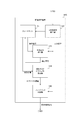
- FIG. 2 is a block diagram showing a configuration example of the information processing apparatus 120 according to the first embodiment of the present technology.
- the information processing device 120 includes a state machine 121, a three-dimensional attitude detector 122, a state difference detector 123, an operation guide object generator 124, and a feedback control unit 125.
- the state machine 121 shifts to any of a plurality of states based on the detection results of the three-dimensional attitude detector 122 and the state difference detector 123.
- the state of the state machine 121 includes, for example, an undetected state, a detected state, an operating state, an operation instruction state, and a selected state.
- the undetected state corresponds to a state in which a predetermined part (hand, etc.) of the user is not detected by the three-dimensional posture detector 122.
- the detection state corresponds to a state in which a predetermined part (hand or the like) of the user is detected by the three-dimensional posture detector 122.
- the operating state corresponds to a state in which the posture of the captured user and the expected posture expected of the user substantially match.
- substantially matching indicates that the difference in posture is within a predetermined allowable value.
- the operation instruction state corresponds to a state in which the gesture expected by the user is displayed on the display device 130.
- the selected state corresponds to the state in which the gesture displayed in the operation instruction state is executed. The conditions for transitioning to each state will be described later.
- the state machine 121 generates information indicating the expected posture, which is the posture expected from the user, and supplies the information to the state difference detector 123, and supplies the state information indicating the current state to the operation guide object generator 124.
- the information indicating the expected posture includes, for example, the coordinates of the joints of the human body in the three-dimensional coordinate system.
- the three-dimensional posture detector 122 detects the user's three-dimensional posture as an input posture by using the image data from the image pickup device 110. First, the three-dimensional posture detector 122 performs image recognition processing on the image data and detects whether or not a predetermined portion (hand or the like) of the user exists in the image data. Then, the three-dimensional posture detector 122 supplies the state machine 121 with a detection result indicating the presence or absence of a hand or the like.
- the three-dimensional posture detector 122 When a hand or the like is detected by image recognition, the three-dimensional posture detector 122 then detects the user's three-dimensional posture as an input posture, and the state machine 121 and the state difference detector provide information indicating the input posture. It is supplied to 123 and the feedback control unit 125.
- the information indicating the input posture includes, for example, the coordinates of the joints of the human body in the three-dimensional coordinate system.
- the three-dimensional attitude detector 122 is an example of the attitude detector described in the claims.
- the state difference detector 123 detects the difference between the expected attitude from the state machine 121 and the input attitude from the three-dimensional attitude detector 122.
- the state difference detector 123 supplies a detection signal indicating the difference to the state machine 121.
- the operation guide object generator 124 generates a guide object corresponding to the state of the state machine 121.
- the operation guide object generator 124 supplies the object information indicating the generated guide object to the feedback control unit 125.
- An example of a guide object for each state will be described later.
- the feedback control unit 125 generates a display control signal for displaying the guide object from the operation guide object generator 124 and supplies it to the display device 130.
- the feedback control unit 125 is an example of the control unit described in the claims.
- the feedback control unit 125 first causes the display device 130 to display a guide object indicating the expected posture. After that, the three-dimensional attitude detector 122 detects the input attitude. Then, when the input posture substantially matches the expected posture, the feedback control unit 125 causes the display device 130 to display a predetermined gesture expected from the user.
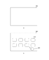
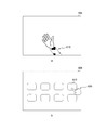
- FIG. 3 is a diagram showing an example of image data and a UI screen in the undetected state in the first embodiment of the present technology.
- a is a diagram showing an example of the image data 500 in the undetected state
- b in the figure is a diagram showing an example of the UI screen 600 in the undetected state.
- On the UI screen 600 for example, a plurality of menu buttons including the menu button 610 are arranged. A predetermined order is assigned to each of the menu buttons, and the content of the order is described.
- the three-dimensional posture detector 122 notifies the state machine 121 of the hand detection failure, and the state machine 121 shifts to the undetected state.
- the operation guide object generator 124 generates a semi-transparent three-dimensional object showing the expected posture in the undetected state as the guide object 620.
- This guide object 620 is synthesized, for example, in a place (lower right, etc.) where there is no menu button 610 in the UI screen 600. Further, for example, as the expected posture, a posture in which the index finger of the hand is raised and the other fingers are bent is used. Further, the display color of the guide object 620 at this time is C1.
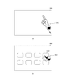
- FIG. 4 is a diagram showing an example of image data and a UI screen in the detection state in the first embodiment of the present technology.
- a is a diagram showing an example of image data 501 in the detection state
- b in the figure is a diagram showing an example of the UI screen 601 in the detection state.
- the posture of the hand 510 (that is, the input posture) is the one in which all the fingers are extended, and does not substantially match the expected posture indicated by the guide object 620.
- the three-dimensional posture detector 122 notifies the state machine 121 of the success of hand detection, and the state machine 121 shifts from the undetected state to the detected state.
- the feedback control unit 125 changes the display color of the guide object 620 from C1 to C2 when the detection state is entered. By this control, the user is fed back that the state machine 121 has shifted to the detection state.
- FIG. 5 is a diagram showing an example of image data and a UI screen before the movement of the hand in the operation state in the first embodiment of the present technology.
- a is a diagram showing an example of image data 502 before the movement of the hand in the operating state
- b in the figure is a diagram showing an example of the UI screen 602 before the movement of the hand in the operating state.
- the state difference detector 123 notifies the state machine 121 of the difference within the permissible value, and the state machine 121 shifts from the detection state to the operation state.
- the feedback control unit 125 changes the display color of the guide object 620 from C2 to C3 when the operation state is entered. By this control, the user is fed back that the state machine 121 has shifted to the operating state.
- the feedback control unit 125 changes the display color at the time of the state transition, so that the user can accurately grasp the current state. As a result, erroneous operation can be prevented.
- FIG. 6 is a diagram showing an example of image data and a UI screen after the movement of the hand in the operating state according to the first embodiment of the present technology.
- a is a diagram showing an example of image data 503 after the movement of the hand in the operating state
- b in the figure is a diagram showing an example of the UI screen 603 after the movement of the hand in the operating state.
- the position of the hand 510 in the newly captured image data 503 in the operating state is different from the position in the previous image data 502.
- the dotted line of a indicates the hand 510 before the movement
- the arrow indicates the movement direction and the movement distance.
- the three-dimensional posture detector 122 supplies the position of the hand 510 after the movement to the feedback control unit 125, and the feedback control unit 125 follows the movement of the hand 510 as illustrated in b in the figure.
- the dotted line b indicates the guide object 620 before the movement
- the arrow indicates the movement direction and the movement distance.
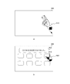
- FIG. 7 is a diagram showing an example of image data and a UI screen in the operation instruction state in the first embodiment of the present technology.
- a is a diagram showing an example of image data 504 in the operation instructed state
- b in the figure is a diagram showing an example of the UI screen 604 in the operation instructed state.
- the feedback control unit 125 moves the guide object 620 to the menu button 610 following the movement of the hand 510.
- the three-dimensional posture detector 122 supplies the input posture information including the coordinates of the index finger to the state machine 121, and the state machine 121 shifts from the operation state to the operation instruction state.
- the feedback control unit 125 displays a predetermined gesture expected from the user on the UI screen 604 by displaying the animation of the guide object 620.
- animation display means that the shape of the guide object 620 changes with the passage of time.
- the feedback control unit 125 displays, for example, a gesture of moving the index finger up and down while bending a finger other than the index finger. This gesture is instructed by an animation of the movement of the index finger of the guide object 620 repeatedly moving up and down at regular intervals.
- this gesture (that is, animation display) indicates a selection operation for the user to select a menu button. By this control, the user is fed back what kind of gesture (selection operation) should be performed next.
- This feedback can encourage the user to operate correctly and prevent erroneous operation.
- the number of redoing operations is reduced, and the convenience of the information processing system 100 is improved.
- the state machine 121 supplies a plurality of expected postures (for example, a posture in which the index finger is raised and a posture in which the index finger is lowered) constituting the selection operation to the state difference detector 123.
- the state difference detector 123 detects the difference between the expected posture and the input posture and returns it to the state machine 121.
- the state machine 121 can determine whether or not the selection operation has been performed based on the difference between them.
- the feedback control unit 125 animates the movement of the index finger of the guide object 620 repeatedly moving up and down at a fixed cycle (in other words, the movement of pressing something), but it may also display other movements in animation. can.
- the feedback control unit 125 can animate the paying motion, the grasping motion, the picking motion, and the like.
- the feedback control unit 125 provides feedback by changing the display color of the guide object and displaying the animation, but the present invention is not limited to this configuration.
- the feedback control unit 125 can also display a text indicating the current state instead of changing the display color.
- a speaker may be further provided, and the feedback control unit 125 may output the current state as audio instead of changing the display color.
- the feedback control unit 125 can also display text explaining the next gesture instead of displaying the animation.
- a speaker may be further provided, and the feedback control unit 125 may output the explanation of the next gesture by voice instead of displaying the animation.
- FIG. 8 is a diagram showing an example of image data and a UI screen in the selected state in the first embodiment of the present technology.
- a is a diagram showing an example of image data 505 in the selected state
- b in the figure is a diagram showing an example of the UI screen 605 in the selected state.
- the state machine 121 shifts to the selected state.
- the feedback control unit 125 changes the color of the selected menu button 610 and accepts the order corresponding to the menu button 610. Display message 630.
- the information processing system 100 performs the settlement processing of the charge related to the order.
- FIG. 9 is a diagram showing an example of image data and a UI screen when the detection state is returned to in the first embodiment of the present technology.
- a is a diagram showing an example of image data 506 when the detection state is returned
- b in the figure is a diagram showing an example of the UI screen 606 when the detection state is returned.
- the state machine 121 shifts from the selected state to the detected state.
- the feedback control unit 125 returns the display color of the guide object 620 from C3 to C2 when the detection state is entered. If the three-dimensional posture detector 122 fails to detect the hand in the selected state, the state machine 121 shifts from the selected state to the undetected state.
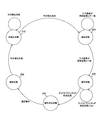
- FIG. 10 is an example of a state transition diagram of the state machine 121 according to the first embodiment of the present technology.
- the state of the state machine 121 includes an undetected state 310, a detected state 320, an operating state 330, an operation instruction state 340, and a selected state 350.
- the initial state is set to, for example, the undetected state 310.
- the state machine 121 remains in the undetected state 310. On the other hand, when the three-dimensional posture detector 122 succeeds in detecting the hand, the state machine 121 shifts to the detection state 320.
- the state machine 121 In the detection state 320, if the input posture does not match the expected posture, the state machine 121 remains in the detection state 320. On the other hand, when the input posture substantially matches the expected posture, the state machine 121 shifts to the operating state 330.
- the state machine 121 In the operation state 330, when the guide object is not in a predetermined position (position of the menu button 610, etc.), the state machine 121 remains in the operation state 330. On the other hand, when the guide object exists at a predetermined position for a certain period of time or longer, the state machine 121 shifts to the operation instruction state 340.
- the state machine 121 shifts to the selection state 350. If the three-dimensional posture detector 122 fails to detect the hand in the selected state 350, the state machine 121 shifts to the undetected state 310. Further, even when the three-dimensional posture detector 122 fails to detect the hand in the detection state 320, the operation state 330, and the operation instruction state 340, the state machine 121 shifts to the undetected state 310. In the figure, the arrow indicating the transition from the detection state 320, the operation state 330, and the operation instruction state 340 to the undetected state 310 and the transition condition are omitted for convenience of description.
- the state machine 121 shifts to the detection state 320.
- the arrow indicating the transition from the operation state 330, the operation instruction state 340, and the selection state 350 to the detection state 320 and the transition condition are omitted for convenience of description.
- FIG. 11 is a flowchart showing an example of the operation of the information processing system 100 according to the first embodiment of the present technology. This operation is started, for example, when a predetermined application for performing gesture input is executed.
- the image pickup device 110 captures image data (step S911). Further, the information processing apparatus 120 acquires an input posture by image recognition for the image data (step S912), and detects the difference between the input posture and the expected posture (step S913). The information processing device 120 determines the current state based on the detection result (step S914).
- the information processing device 120 determines whether or not the state has shifted to the undetected state (step S915).
- the information processing apparatus 120 generates a guide object of the display color C1 for notifying the undetected state (step S916).
- step S915 When the state has not shifted to the undetected state (step S915: No), the information processing apparatus 120 determines whether or not the state has shifted to the detected state (step S917). When the state shifts to the detection state (step S917: Yes), the information processing apparatus 120 generates a guide object of the display color C2 for notifying the detection state (step S918).
- step S917 When the state has not shifted to the detection state (step S917: No), the information processing apparatus 120 determines whether or not the state has shifted to the operation state (step S919). When the operation state is entered (step S919: Yes), the information processing apparatus 120 generates a guide object of the display color C3 for notifying the operation state (step S920).
- the information processing device 120 changes the display color of the guide object at the time of transition to the detection state or the operation state, but the configuration is not limited to this.
- the information processing apparatus 120 can also change the transmittance of the guide object at the time of transition to the detection state or the operation state.
- the information processing device 120 can change the shape of the guide object to that of a person, a robot, a character, or the like at the time of transition to the detection state or the operation state.
- step S919: No the information processing apparatus 120 determines whether or not it has shifted to the operation instruction state (step S921). When the state shifts to the operation instruction state (step S921: Yes), the information processing apparatus 120 generates a display control signal for displaying the guide object in animation (step S922). When the state has not shifted to the operation instruction state (step S921: No), the information processing device 120 controls the display device 130 according to the selection operation and feeds back the state to the user (step S923).
- the information processing device 120 controls the display device 130 to feed back the state to the user (step S923). After step S923, the information processing apparatus 120 repeatedly executes step S911 and subsequent steps.
- the information processing device 120 when the input posture substantially matches the expected posture, the information processing device 120 causes the display device 130 to display the gesture expected by the user. It is possible to let the user understand the operation to be performed. As a result, erroneous operation can be suppressed and the convenience of the information processing system 100 can be improved.
- Second Embodiment> when the input posture substantially matches the expected posture, the information processing device 120 causes the display device 130 to animate the guide object, but compared with the case where the animation is not displayed. , The delay time required for display processing may increase.
- the information processing device 120 of the second embodiment is different from the first embodiment in that it displays an animation when necessary based on the proficiency level of the user.
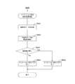
- FIG. 12 is a flowchart showing an example of the operation of the information processing system 100 in the second embodiment of the present technology.
- the operation of the information processing system 100 of the second embodiment is different from that of the first embodiment in that step S930 is executed instead of step S922.
- step S921 When the state shifts to the operation instruction state (step S921: Yes), the information processing device 120 executes an animation display determination process for determining whether or not to display the animation (step S930). After step S930, the information processing apparatus 120 executes step S923.
- FIG. 13 is a flowchart showing an example of animation display determination processing according to the first embodiment of the present technology.
- the feedback control unit 125 in the information processing device 120 generates time-series data indicating changes in the joint coordinates of the user in the input posture on the time-series (step S931). Then, the feedback control unit 125 performs frequency analysis of the time series data and extracts high frequency components having a frequency equal to or higher than a predetermined value (step S932).
- the feedback control unit 125 determines whether or not the user's proficiency level is higher than a predetermined threshold value based on the high frequency component (step S933). For example, when the level of the high frequency component is higher than the predetermined level, the proficiency level is determined to be below the threshold value, and when the level of the high frequency component is below the predetermined level, the proficiency level is determined to be higher than the threshold value. NS.
- step S933: No When the proficiency level is below the threshold value (step S933: No), the feedback control unit 125 turns on the animation display flag (step S934). On the other hand, when the proficiency level is higher than the threshold value (step S933: Yes), the feedback control unit 125 turns off the animation display flag (step S935).
- the animation display flag is a flag indicating whether or not to display the animation in the subsequent step S923. When the animation display flag is on, the guide object is displayed in animation in step S923.
- step S934 or S935 the feedback control unit 125 ends the animation display determination process.
- the information processing device 120 does not animate the guide object when the user's proficiency level is high, so that unnecessary processing is reduced and the delay time is shortened. can do.
- the processing procedure described in the above-described embodiment may be regarded as a method having these series of procedures, or as a program for causing a computer to execute these series of procedures or as a recording medium for storing the program. You may catch it.
- this recording medium for example, a CD (Compact Disc), MD (MiniDisc), DVD (Digital Versatile Disc), memory card, Blu-ray Disc (Blu-ray (registered trademark) Disc) and the like can be used.
- the present technology can have the following configurations.
- a posture detector that detects the user's posture as an input posture after the expected posture, which is the posture expected of the user, is displayed on the display device.
- An information processing device including a control unit that controls the display device to display a predetermined gesture expected of the user when the input posture substantially matches the expected posture.
- the control for displaying the gesture is a control for displaying a predetermined object in animation on the display device.
- the control unit determines whether or not the proficiency level of the user is higher than a predetermined threshold value, and if the proficiency level is higher than the threshold value, animates the object.
- Information processing device wherein the control unit determines whether or not the proficiency level of the user is higher than a predetermined threshold value, and if the proficiency level is higher than the threshold value, animates the object.
- the control unit analyzes time-series data indicating changes in the joints of the user with the passage of time, and determines whether or not the proficiency level is higher than the threshold value based on the analysis result.
- the plurality of states include an undetected state and a detected state.
- the posture detector further determines whether or not a predetermined portion of the user is present in the captured image data, and further determines.
- the state machine shifts to the undetected state when the part does not exist in the image data, and shifts to the detected state when the part exists in the image data.
- the information processing device displays a predetermined object indicating the expected posture on the display device when the state machine shifts to the undetected state.
- the plurality of states further include an operating state. When the input posture substantially matches the expected posture, the state machine shifts to the operating state.
- the information processing device (6), wherein the control unit moves the object according to the input posture when the state machine shifts to the operating state.
- the plurality of states further include an operation instruction state. When the object moves to a predetermined position, the state machine shifts to the operation instruction state, and the state machine shifts to the operation instruction state.
- the information processing device displays the gesture on the display device when the state machine shifts to the operation instruction state.
- An imaging device that generates an captured image and Display device and A posture detector that analyzes the captured image and detects the user's posture as an input posture after the expected posture, which is the posture expected of the user, is displayed on the display device.
- An information processing system including a control unit that controls the display device to display a predetermined gesture expected of the user when the input posture substantially matches the expected posture.
- An information processing method including a control procedure for controlling the display device to display a predetermined gesture expected of the user when the input posture substantially matches the expected posture.
- Imaging device 120 Information processing device 121 State machine 122 3D attitude detector 123 State difference detector 124 Operation guide Object generator 125 Feedback control unit 130 Display device
Landscapes
- Engineering & Computer Science (AREA)
- Theoretical Computer Science (AREA)
- General Engineering & Computer Science (AREA)
- Physics & Mathematics (AREA)
- General Physics & Mathematics (AREA)
- Human Computer Interaction (AREA)
- Computer Vision & Pattern Recognition (AREA)
- User Interface Of Digital Computer (AREA)
- Image Analysis (AREA)
- Position Input By Displaying (AREA)
Abstract
非接触のユーザインターフェースを有するシステムにおいて、利便性を向上させる。 情報処理装置は、姿勢検出器、および、制御部を具備する。この情報処理装置において姿勢検出器は、利用者に期待する姿勢である期待姿勢が表示装置に表示された後に利用者の姿勢を入力姿勢として検出する。また、情報処理装置において制御部は、入力姿勢が期待姿勢に略一致する場合には利用者に期待する所定のジェスチャを表示装置に表示させる制御を行う。
Description
本技術は、情報処理装置に関する。詳しくは、ユーザインターフェースを有する情報処理装置、情報処理システム、および、これらにおける情報処理方法、並びに、当該方法をコンピュータに実行さるためのプログラムに関する。
従来より、ジェスチャインターフェースなど、操作の際に機器への物理的な接触を要しない非接触型のUI(User Interface)が様々な分野で用いられている。この非接触型のUIは衛生的であるが、物理的なフィードバックがないため、接触型のUIと比較して誤操作が生じやすい傾向にある。そこで、複数のランプを配列し、利用者の手の動きに追従して、それらの点灯状態を変化させることにより手の動きの補足状態を利用者に把握させる非接触型のUIが提案されている(例えば、特許文献1参照。)。
上述の従来技術では、手の動きの補足状態を利用者に把握させることにより、ジェスチャ入力を行う際の誤操作の防止を図っている。しかしながら、上述のUIでは、利用者が操作に習熟していない場合に、次にどのようなジェスチャを行えばよいかがわからなくなることがあり、利便性が低下してしまうという問題がある。
本技術はこのような状況に鑑みて生み出されたものであり、非接触のユーザインターフェースを有するシステムにおいて、利便性を向上させることを目的とする。
本技術は、上述の問題点を解消するためになされたものであり、その第1の側面は、利用者に期待する姿勢である期待姿勢が表示装置に表示された後に前記利用者の姿勢を入力姿勢として検出する姿勢検出器と、前記入力姿勢が前記期待姿勢に略一致する場合には前記利用者に期待する所定のジェスチャを前記表示装置に表示させる制御を行う制御部とを具備する情報処理装置、および、当該情報処理装置における情報処理方法、並びに、当該方法をコンピュータに実行させるためのプログラムである。これにより、次のジェスチャを利用者に把握させるという作用をもたらす。
また、この第1の側面において、前記ジェスチャを表示させる制御は、所定のオブジェクトを前記表示装置にアニメーション表示させる制御であってもよい。これにより、入力姿勢が期待姿勢に略一致する際に、オブジェクトがアニメーション表示されるという作用をもたらす。
また、この第1の側面において、前記制御部は、前記利用者の習熟度が所定の閾値より高いか否かを判定して前記習熟度が前記閾値より高い場合には前記オブジェクトをアニメーション表示させてもよい。これにより、習熟度が低い場合にアニメーション表示が省略されるという作用をもたらす。
また、この第1の側面において、前記制御部は、時間の経過に伴う前記利用者の関節の変化を示す時系列データを解析して当該解析結果に基づいて前記習熟度が前記閾値より高いか否かを判定してもよい。これにより、時系列データの解析により習熟度が閾値より高いか否かが判定されるという作用をもたらす。
また、この第1の側面において、複数の状態のいずれかに移行するステートマシンをさらに具備することもできる。これにより、状態に応じた表示が行われるという作用をもたらす。
また、この第1の側面において、前記複数の状態は、未検出状態および検出状態を含み、前記姿勢検出器は、撮像された画像データ内に前記利用者の所定の部位が存在するか否かをさらに判定し、前記ステートマシンは、前記画像データ内に前記部位が存在しない場合には前記未検出状態に移行し、前記画像データ内に前記部位が存在する場合には前記検出状態に移行し、前記制御部は、前記ステートマシンが前記未検出状態に移行した場合には前記期待姿勢を示す所定のオブジェクトを前記表示装置に表示させてもよい。これにより、画像データ内に所定の部位が存在する際に検出状態に移行するという作用をもたらす。
また、この第1の側面において、前記複数の状態は、操作状態をさらに含み、前記ステートマシンは、前記入力姿勢が前記期待姿勢に略一致する場合には前記操作状態に移行し、前記制御部は、前記ステートマシンが前記操作状態に移行した場合には前記オブジェクトを前記入力姿勢に追従して移動させてもよい。これにより、入力姿勢が期待姿勢に略一致する際に操作状態に移行するという作用をもたらす。
また、この第1の側面において、前記複数の状態は、動作指示状態をさらに含み、前記ステートマシンは、前記オブジェクトが所定の位置に移動した場合には前記動作指示状態に移行し、前記制御部は、前記ステートマシンが前記動作指示状態に移行した場合には前記ジェスチャを前記表示装置に表示させてもよい。これにより、オブジェクトが所定の位置に移動した際に動作指示状態に移行するという作用をもたらす。
また、本技術の第2の側面は、撮像画像を生成する撮像装置と、表示装置と、利用者に期待する姿勢である期待姿勢が前記表示装置に表示された後に前記撮像画像を解析して前記利用者の姿勢を入力姿勢として検出する姿勢検出器と、前記入力姿勢が前記期待姿勢に略一致する場合には前記利用者に期待する所定のジェスチャを前記表示装置に表示させる制御を行う制御部とを具備する情報処理システムである。これにより、表示装置への表示により、次のジェスチャを利用者に把握させるという作用をもたらす。
以下、本技術を実施するための形態(以下、実施の形態と称する)について説明する。説明は以下の順序により行う。
1.第1の実施の形態(入力姿勢が期待姿勢の際にアニメーション表示させる例)
2.第2の実施の形態(入力姿勢が期待姿勢の際に、習熟度に応じてアニメーション表示させる例)
1.第1の実施の形態(入力姿勢が期待姿勢の際にアニメーション表示させる例)
2.第2の実施の形態(入力姿勢が期待姿勢の際に、習熟度に応じてアニメーション表示させる例)
<1.第1の実施の形態>
[情報処理システムの構成例]
図1は、本技術の第1の実施の形態における情報処理システム100の一構成例を示す全体図である。この情報処理システム100は、非接触型のUIを提供するシステムであり、撮像装置110、情報処理装置120および表示装置130を備える。情報処理システム100内の装置のそれぞれは、例えば、ドライブスルー型の店舗に設置される自動精算機内に配置される。あるいは、情報処理システム100内の装置は、例えば、券売機や自動販売機の内部に配置される。
[情報処理システムの構成例]
図1は、本技術の第1の実施の形態における情報処理システム100の一構成例を示す全体図である。この情報処理システム100は、非接触型のUIを提供するシステムであり、撮像装置110、情報処理装置120および表示装置130を備える。情報処理システム100内の装置のそれぞれは、例えば、ドライブスルー型の店舗に設置される自動精算機内に配置される。あるいは、情報処理システム100内の装置は、例えば、券売機や自動販売機の内部に配置される。
撮像装置110は、画像を撮像して画像データを生成するものである。撮像装置110として、CMOS(Complementary MOS)イメージセンサやToF(Time of Flight)センサが用いられる。あるいは、ミリ波センサや、LIDAR(Light Detection and Ranging Laser Imaging Detection and Ranging)が撮像装置110として用いられる。情報処理システム100の利用者200が撮像装置110の前に立っている場合には、その利用者200の身体の少なくとも一部(手など)が撮像される。撮像装置110は、撮像した画像データを信号線119を介して情報処理装置120に供給する。
表示装置130は、情報処理装置120の制御に従って、UI画面を表示するものである。
情報処理装置120は、画像データに基づいてUI画面の表示内容を制御するものである。この情報処理装置120は、UI画面の表示内容を制御するための表示制御信号を生成し、信号線129を介して表示装置130に供給する。このように画像データに基づいて情報処理装置120がUI画面の表示内容を制御することにより、利用者は非接触で情報処理システム100を操作することができ、非接触型のUIが実現される。
なお、情報処理システム100内の装置のそれぞれは、同一の機器(自動精算機など)内に配置することもできるし、複数の機器に分散して配置することもできる。複数の機器に分散して配置する場合、例えば、撮像装置110および表示装置130が自動精算機などに配置され、情報処理装置120は、ネットワークを介して自動精算機等に接続されたサーバなどに配置される。
[情報処理装置の構成例]
図2は、本技術の第1の実施の形態における情報処理装置120の一構成例を示すブロック図である。この情報処理装置120は、ステートマシン121、3次元姿勢検出器122、状態差分検出器123、操作ガイドオブジェクト生成器124およびフィードバック制御部125を備える。
図2は、本技術の第1の実施の形態における情報処理装置120の一構成例を示すブロック図である。この情報処理装置120は、ステートマシン121、3次元姿勢検出器122、状態差分検出器123、操作ガイドオブジェクト生成器124およびフィードバック制御部125を備える。
ステートマシン121は、3次元姿勢検出器122や状態差分検出器123の検出結果に基づいて複数の状態のいずれかに移行するものである。ここで、ステートマシン121の状態は、例えば、未検出状態、検出状態、操作状態、動作指示状態および選択状態を含む。
未検出状態は、3次元姿勢検出器122により利用者の所定の部位(手など)が検出されていない状態に該当する。一方、検出状態は、3次元姿勢検出器122により利用者の所定の部位(手など)が検出された状態に該当する。また、操作状態は、撮像された利用者の姿勢と、その利用者に期待される期待姿勢とが略一致する状態に該当する。ここで、「略一致」は、姿勢の差分が所定の許容値以内であることを示す。動作指示状態は、利用者に期待されるジェスチャを表示装置130に表示させる状態に該当する。選択状態は、動作指示状態で表示されたジェスチャが実行された状態に該当する。それぞれの状態への移行条件については後述する。
また、ステートマシン121は、利用者に期待する姿勢である期待姿勢を示す情報を生成して状態差分検出器123に供給するとともに、現在の状態を示す状態情報を操作ガイドオブジェクト生成器124に供給する。ここで、期待姿勢を示す情報は、例えば、3次元の座標系における人体の関節のそれぞれの座標を含む。
3次元姿勢検出器122は、撮像装置110からの画像データを用いて、利用者の3次元的な姿勢を入力姿勢として検出するものである。まず、3次元姿勢検出器122は、画像データに対して画像認識処理を行い、画像データ内に利用者の所定の部位(手など)が存在するか否かを検出する。そして、3次元姿勢検出器122は、手などの有無を示す検出結果をステートマシン121に供給する。
画像認識により手などを検出した場合、3次元姿勢検出器122は、次に利用者の3次元的な姿勢を入力姿勢として検出し、その入力姿勢を示す情報をステートマシン121、状態差分検出器123およびフィードバック制御部125に供給する。入力姿勢を示す情報は、例えば、3次元の座標系における人体の関節のそれぞれの座標を含む。なお、3次元姿勢検出器122は、特許請求の範囲に記載の姿勢検出器の一例である。
状態差分検出器123は、ステートマシン121からの期待姿勢と、3次元姿勢検出器122からの入力姿勢との差分を検出するものである。この状態差分検出器123は、差分を示す検出信号をステートマシン121に供給する。
操作ガイドオブジェクト生成器124は、ステートマシン121の状態に対応するガイドオブジェクトを生成するものである。この操作ガイドオブジェクト生成器124は、生成したガイドオブジェクトを示すオブジェクト情報をフィードバック制御部125に供給する。状態毎のガイドオブジェクトの例については、後述する。
フィードバック制御部125は、操作ガイドオブジェクト生成器124からのガイドオブジェクトを表示させるための表示制御信号を生成し、表示装置130に供給するものである。なお、フィードバック制御部125は、特許請求の範囲に記載の制御部の一例である。
上述の情報処理装置110において、フィードバック制御部125は、まず、期待姿勢を示すガイドオブジェクトを表示装置130に表示させる。その後に、3次元姿勢検出器122は、入力姿勢を検出する。そして、入力姿勢が期待姿勢と略一致する際にフィードバック制御部125は、利用者に期待する所定のジェスチャを表示装置130に表示させる。
[情報処理システムの動作例]
図3は、本技術の第1の実施の形態における未検出状態のときの画像データおよびUI画面の一例を示す図である。同図におけるaは、未検出状態のときの画像データ500の一例を示す図であり、同図におけるbは、未検出状態のときのUI画面600の一例を示す図である。UI画面600には、例えば、メニューボタン610を含む複数のメニューボタンが配列される。メニューボタンのそれぞれには、所定の注文が割り当てられ、その注文の内容が記載される。
図3は、本技術の第1の実施の形態における未検出状態のときの画像データおよびUI画面の一例を示す図である。同図におけるaは、未検出状態のときの画像データ500の一例を示す図であり、同図におけるbは、未検出状態のときのUI画面600の一例を示す図である。UI画面600には、例えば、メニューボタン610を含む複数のメニューボタンが配列される。メニューボタンのそれぞれには、所定の注文が割り当てられ、その注文の内容が記載される。
同図におけるaに例示するように、撮像された画像データ500内に、利用者の所定の部位(手など)が写っていないものとする。この場合に、3次元姿勢検出器122は、手の検出失敗をステートマシン121に通知し、ステートマシン121は、未検出状態に移行する。
また、同図におけるbに例示するように、操作ガイドオブジェクト生成器124は、未検出状態において期待姿勢を示す半透明の3次元のオブジェクトをガイドオブジェクト620として生成する。このガイドオブジェクト620は、例えば、UI画面600内のメニューボタン610の無い箇所(右下など)に合成される。また、例えば、期待姿勢として、手の人差し指を立て、それ以外の指を曲げた姿勢が用いられる。また、このときのガイドオブジェクト620の表示色をC1とする。
図4は、本技術の第1の実施の形態における検出状態のときの画像データおよびUI画面の一例を示す図である。同図におけるaは、検出状態のときの画像データ501の一例を示す図であり、同図におけるbは、検出状態のときのUI画面601の一例を示す図である。
同図におけるaに例示するように、撮像された画像データ501内に、利用者の所定の部位(手510など)が写ったものとする。ただし、手510の姿勢(すなわち、入力姿勢)は、全ての指を伸ばしたものであり、ガイドオブジェクト620の示す期待姿勢に略一致しないものとする。この場合に、3次元姿勢検出器122は、手の検出成功をステートマシン121に通知し、ステートマシン121は、未検出状態から検出状態に移行する。
また、同図におけるbに例示するように、フィードバック制御部125は、検出状態に移行した際にガイドオブジェクト620の表示色をC1からC2に変更する。この制御により、ステートマシン121が検出状態に移行したことが利用者にフィードバックされる。
図5は、本技術の第1の実施の形態における操作状態で手の移動前の画像データおよびUI画面の一例を示す図である。同図におけるaは、操作状態で手の移動前の画像データ502の一例を示す図であり、同図におけるbは、操作状態で手の移動前のUI画面602の一例を示す図である。
同図におけるaに例示するように、撮像された画像データ502内に利用者の所定の部位(手510など)が写り、その姿勢が、ガイドオブジェクト620の示す期待姿勢に略一致したものとする。この場合に、状態差分検出器123は、許容値以内の差分をステートマシン121に通知し、ステートマシン121は、検出状態から操作状態に移行する。
また、同図におけるbに例示するように、フィードバック制御部125は、操作状態に移行した際にガイドオブジェクト620の表示色をC2からC3に変更する。この制御により、ステートマシン121が操作状態に移行したことが利用者にフィードバックされる。
図4および図5に例示したように、状態の遷移の際にフィードバック制御部125が表示色を変更することにより、利用者は、現在の状態を正確に把握することができる。これにより、誤操作を防止することができる。
図6は、本技術の第1の実施の形態における操作状態で手の移動後の画像データおよびUI画面の一例を示す図である。同図におけるaは、操作状態で手の移動後の画像データ503の一例を示す図であり、同図におけるbは、操作状態で手の移動後のUI画面603の一例を示す図である。
同図におけるaに例示するように、操作状態において新たに撮像された画像データ503内の手510の位置が、その前の画像データ502内の位置と異なるものとする。同図におけるaの点線は、移動前の手510を示し、矢印は、移動方向および移動距離を示す。
この場合に、3次元姿勢検出器122は、手510の移動後の位置をフィードバック制御部125に供給し、フィードバック制御部125は、同図におけるbに例示するように手510の移動に追従してガイドオブジェクト620を移動させる。同図におけるbの点線は、移動前のガイドオブジェクト620を示し、矢印は、移動方向および移動距離を示す。
図7は、本技術の第1の実施の形態における動作指示状態のときの画像データおよびUI画面の一例を示す図である。同図におけるaは、動作指示状態のときの画像データ504の一例を示す図であり、同図におけるbは、動作指示状態のときのUI画面604の一例を示す図である。
同図におけるaに例示するように利用者が手510を期待姿勢にし、メニューボタン610に対応する位置まで移動させたものとする。
その場合、同図におけるbに例示するようにフィードバック制御部125は、手510の移動に追従してガイドオブジェクト620をメニューボタン610まで移動させる。このとき、移動後のガイドオブジェクト620の人差し指の少なくとも一部が、一定時間以上に亘ってメニューボタン610と重なったものとする。その際に、3次元姿勢検出器122は、人差し指の座標を含む入力姿勢の情報をステートマシン121に供給し、ステートマシン121は、操作状態から動作指示状態に移行する。
動作指示状態において、フィードバック制御部125は、ガイドオブジェクト620のアニメーション表示により、利用者に期待する所定のジェスチャをUI画面604に表示させる。ここで、「アニメーション表示」は、時間の経過に伴ってガイドオブジェクト620の形状が変化することを意味する。フィードバック制御部125は、例えば、人差し指以外の指を曲げたまま、その人差し指を上下させる内容のジェスチャを表示させる。このジェスチャは、ガイドオブジェクト620の人差し指が一定の周期で繰り返し上下する動作のアニメーションにより指示される。また、このジェスチャ(すなわち、アニメーション表示)は、メニューボタンを利用者が選択するための選択動作を示す。この制御により、次にどのようなジェスチャ(選択動作)を行えばよいかが利用者にフィードバックされる。
このフィードバックにより、利用者に正しい動作を促し、誤操作を防止することができる。誤操作の防止により、操作のやり直しが少なくなり、情報処理システム100の利便性が向上する。
また、動作指示状態において、ステートマシン121は、選択動作を構成する複数の期待姿勢(例えば、人差し指を上げた姿勢と、人差し指を下げた姿勢)を状態差分検出器123に供給する。状態差分検出器123は、それらの期待姿勢と、入力姿勢との差分を検出してステートマシン121に返す。ステートマシン121は、それらの差分により、選択動作が行われたか否かを判断することができる。
なお、フィードバック制御部125は、ガイドオブジェクト620の人差し指が一定の周期で繰り返し上下する動作(言い換えれば、何かを押す動作)をアニメーション表示させているが、これ以外の動作をアニメーション表示させることもできる。例えば、フィードバック制御部125は、払う動作、握る動作や摘まむ動作などをアニメーション表示させることもできる。
また、フィードバック制御部125は、ガイドオブジェクトの表示色の変更と、アニメーション表示とによりフィードバックを行っているが、この構成に限定されない。フィードバック制御部125は、表示色の変更の代わりに、現在の状態を示すテキストを表示させることもできる。また、スピーカをさらに設け、フィードバック制御部125が、表示色の変更の代わりに、現在の状態を音声出力させることもできる。また、フィードバック制御部125は、アニメーション表示の代わりに、次のジェスチャを説明するテキストを表示させることもできる。また、スピーカをさらに設け、フィードバック制御部125が、アニメーション表示の代わりに、次のジェスチャの説明を音声出力させることもできる。さらに、表示色の変更やアニメーション表示と、テキスト表示や音声出力とを組み合わせることもできる。
図8は、本技術の第1の実施の形態における選択状態のときの画像データおよびUI画面の一例を示す図である。同図におけるaは、選択状態のときの画像データ505の一例を示す図であり、同図におけるbは、選択状態のときのUI画面605の一例を示す図である。
同図におけるaに例示するように利用者が選択動作を行ったものとする。この選択動作に応じて、ステートマシン121は、選択状態に移行する。そして、同図におけるbに例示するように、選択状態に移行した際にフィードバック制御部125は、選択されたメニューボタン610の色を変更し、そのメニューボタン610に対応する注文を受け付けた旨のメッセージ630を表示させる。そして、情報処理システム100は、注文に係る料金の精算処理を行う。
図9は、本技術の第1の実施の形態における検出状態に戻ったときの画像データおよびUI画面の一例を示す図である。同図におけるaは、検出状態に戻ったときの画像データ506の一例を示す図であり、同図におけるbは、検出状態に戻ったときのUI画面606の一例を示す図である。
選択状態において、同図におけるaに例示するように、手510の姿勢がガイドオブジェクト620と不一致になったものとする。この場合に、ステートマシン121は、選択状態から検出状態に移行する。
また、同図におけるbに例示するように、フィードバック制御部125は、検出状態に移行した際に、ガイドオブジェクト620の表示色をC3からC2に戻す。なお、選択状態において、3次元姿勢検出器122が手の検出に失敗した場合、ステートマシン121は、選択状態から未検出状態に移行する。
図10は、本技術の第1の実施の形態におけるステートマシン121の状態遷移図の一例である。ステートマシン121の状態は、未検出状態310、検出状態320、操作状態330、動作指示状態340および選択状態350を含む。初期状態は、例えば、未検出状態310に設定される。
未検出状態310において、3次元姿勢検出器122が手の検出に失敗した場合、ステートマシン121は、未検出状態310のままである。一方、3次元姿勢検出器122が手の検出に成功した場合、ステートマシン121は、検出状態320に移行する。
検出状態320において、入力姿勢が期待姿勢と不一致である場合、ステートマシン121は、検出状態320のままである。一方、入力姿勢が期待姿勢と略一致する場合、ステートマシン121は、操作状態330に移行する。
操作状態330において、ガイドオブジェクトが所定位置(メニューボタン610の位置など)に無い場合、ステートマシン121は、操作状態330のままである。一方、ガイドオブジェクトが一定時間以上に亘って所定位置に存在する場合、ステートマシン121は、動作指示状態340に移行する。
動作指示状態340において選択動作が行われると、ステートマシン121は、選択状態350に移行する。選択状態350において3次元姿勢検出器122が手の検出に失敗した場合、ステートマシン121は、未検出状態310に移行する。また、検出状態320、操作状態330および動作指示状態340において、3次元姿勢検出器122が手の検出に失敗した場合にも、ステートマシン121は、未検出状態310に移行する。なお、同図において、検出状態320、操作状態330および動作指示状態340から未検出状態310への移行を示す矢印と移行条件とは、記載の便宜上、省略されている。
また、操作状態330、動作指示状態340および選択状態350において、入力姿勢が期待姿勢と不一致である場合、ステートマシン121は、検出状態320に移行する。なお、同図において、操作状態330、動作指示状態340および選択状態350から検出状態320への移行を示す矢印と移行条件とは、記載の便宜上、省略されている。
図11は、本技術の第1の実施の形態における情報処理システム100の動作の一例を示すフローチャートである。この動作は、例えば、ジェスチャ入力を行うための所定のアプリケーションが実行されたときに開始される。
撮像装置110は、画像データを撮影する(ステップS911)。また、情報処理装置120は、画像データに対する画像認識により入力姿勢を取得し(ステップS912)、その入力姿勢と期待姿勢との差分を検出する(ステップS913)。情報処理装置120は、検出結果に基づいて、現在の状態を判別する(ステップS914)。
そして、情報処理装置120は、未検出状態に移行したか否かを判断する(ステップS915)。未検出状態に移行した場合(ステップS915:Yes)、情報処理装置120は、未検出状態を通知するための表示色C1のガイドオブジェクトを生成する(ステップS916)。
未検出状態に移行していない場合(ステップS915:No)、情報処理装置120は、検出状態に移行したか否かを判断する(ステップS917)。検出状態に移行した場合(ステップS917:Yes)、情報処理装置120は、検出状態を通知するための表示色C2のガイドオブジェクトを生成する(ステップS918)。
検出状態に移行していない場合(ステップS917:No)、情報処理装置120は、操作状態に移行したか否かを判断する(ステップS919)。操作状態に移行した場合(ステップS919:Yes)、情報処理装置120は、操作状態を通知するための表示色C3のガイドオブジェクトを生成する(ステップS920)。
なお、検出状態や操作状態への移行時に情報処理装置120は、ガイドオブジェクトの表示色を変更しているが、この構成に限定されない。検出状態や操作状態への移行時に情報処理装置120は、ガイドオブジェクトの透過率を変更することもできる。あるいは、検出状態や操作状態への移行時に情報処理装置120は、ガイドオブジェクトの形状を、人、ロボットやキャラクターのものなどに変更することもできる。
操作状態に移行していない場合(ステップS919:No)、情報処理装置120は、動作指示状態に移行したか否かを判断する(ステップS921)。動作指示状態に移行した場合(ステップS921:Yes)、情報処理装置120は、ガイドオブジェクトをアニメーション表示させるための表示制御信号を生成する(ステップS922)。動作指示状態に移行していない場合(ステップS921:No)、情報処理装置120は、選択動作に応じて表示装置130を制御し、状態を利用者にフィードバックする(ステップS923)。
また、ステップS916、S918、S920またはS922の後に情報処理装置120は、表示装置130を制御して状態を利用者にフィードバックする(ステップS923)。ステップS923の後に情報処理装置120は、ステップS911以降を繰り返し実行する。
このように、本技術の第1の実施の形態によれば、入力姿勢が期待姿勢に略一致する際に、利用者に期待するジェスチャを情報処理装置120が表示装置130に表示させるため、次に行うべき動作を利用者に把握させることができる。これにより、誤操作を抑制し、情報処理システム100の利便性を向上させることができる。
<2.第2の実施の形態>
上述の第1の実施の形態では、入力姿勢が前記期待姿勢に略一致する際に情報処理装置120は、表示装置130にガイドオブジェクトをアニメーション表示させていたが、アニメーション表示しない場合と比較して、表示処理に要する遅延時間が長くなるおそれがある。この第2の実施の形態の情報処理装置120は、利用者の習熟度に基づいて、必要な場合にアニメーション表示させる点において第1の実施の形態と異なる。
上述の第1の実施の形態では、入力姿勢が前記期待姿勢に略一致する際に情報処理装置120は、表示装置130にガイドオブジェクトをアニメーション表示させていたが、アニメーション表示しない場合と比較して、表示処理に要する遅延時間が長くなるおそれがある。この第2の実施の形態の情報処理装置120は、利用者の習熟度に基づいて、必要な場合にアニメーション表示させる点において第1の実施の形態と異なる。
図12は、本技術の第2の実施の形態における情報処理システム100の動作の一例を示すフローチャートである。この第2の実施の形態の情報処理システム100の動作は、ステップS922の代わりにステップS930が実行される点において第1の実施の形態と異なる。
動作指示状態に移行した場合(ステップS921:Yes)、情報処理装置120は、アニメーション表示させるか否かを判定するためのアニメーション表示判定処理を実行する(ステップS930)。ステップS930の後に情報処理装置120は、ステップS923を実行する。
図13は、本技術の第1の実施の形態におけるアニメーション表示判定処理の一例を示すフローチャートである。情報処理装置120内のフィードバック制御部125は、入力姿勢における利用者の関節座標の時系列上の変化を示す時系列データを生成する(ステップS931)。そして、フィードバック制御部125は、時系列データを周波数解析して、周波数が所定値以上の高周波数成分を抽出する(ステップS932)。
フィードバック制御部125は、高周波数成分に基づいて、利用者の習熟度が所定の閾値より高いか否かを判定する(ステップS933)。例えば、高周波数成分のレベルが所定レベルより高い場合には、習熟度が閾値以下と判定され、高周波数成分のレベルが所定レべル以下の場合には、習熟度が閾値より高いと判定される。
習熟度が閾値以下の場合(ステップS933:No)、フィードバック制御部125は、アニメーション表示フラグをオンにする(ステップS934)。一方、習熟度が閾値より高い場合(ステップS933:Yes)、フィードバック制御部125は、アニメーション表示フラグをオフにする(ステップS935)。アニメーション表示フラグは、後段のステップS923でアニメーション表示させるか否かを示すフラグである。アニメーション表示フラグがオンの場合に、ステップS923において、ガイドオブジェクトがアニメーション表示される。
ステップS934またはS935の後に、フィードバック制御部125は、アニメーション表示判定処理を終了する。
このように、本技術の第2の実施の形態によれば、利用者の習熟度が高い場合に情報処理装置120がガイドオブジェクトをアニメーション表示させないため、不要な処理を削減して遅延時間を短くすることができる。
なお、上述の実施の形態は本技術を具現化するための一例を示したものであり、実施の形態における事項と、特許請求の範囲における発明特定事項とはそれぞれ対応関係を有する。同様に、特許請求の範囲における発明特定事項と、これと同一名称を付した本技術の実施の形態における事項とはそれぞれ対応関係を有する。ただし、本技術は実施の形態に限定されるものではなく、その要旨を逸脱しない範囲において実施の形態に種々の変形を施すことにより具現化することができる。
また、上述の実施の形態において説明した処理手順は、これら一連の手順を有する方法として捉えてもよく、また、これら一連の手順をコンピュータに実行させるためのプログラム乃至そのプログラムを記憶する記録媒体として捉えてもよい。この記録媒体として、例えば、CD(Compact Disc)、MD(MiniDisc)、DVD(Digital Versatile Disc)、メモリカード、ブルーレイディスク(Blu-ray(登録商標)Disc)等を用いることができる。
なお、本明細書に記載された効果はあくまで例示であって、限定されるものではなく、また、他の効果があってもよい。
なお、本技術は以下のような構成もとることができる。
(1)利用者に期待する姿勢である期待姿勢が表示装置に表示された後に前記利用者の姿勢を入力姿勢として検出する姿勢検出器と、
前記入力姿勢が前記期待姿勢に略一致する場合には前記利用者に期待する所定のジェスチャを前記表示装置に表示させる制御を行う制御部と
を具備する情報処理装置。
(2)前記ジェスチャを表示させる制御は、所定のオブジェクトを前記表示装置にアニメーション表示させる制御である
前記(1)記載の情報処理装置。
(3)前記制御部は、前記利用者の習熟度が所定の閾値より高いか否かを判定して前記習熟度が前記閾値より高い場合には前記オブジェクトをアニメーション表示させる
前記(2)記載の情報処理装置。
(4)前記制御部は、時間の経過に伴う前記利用者の関節の変化を示す時系列データを解析して当該解析結果に基づいて前記習熟度が前記閾値より高いか否かを判定する
前記(3)記載の情報処理装置。
(5)複数の状態のいずれかに移行するステートマシンをさらに具備する
前記(1)から(4)のいずれかに記載の情報処理装置。
(6)前記複数の状態は、未検出状態および検出状態を含み、
前記姿勢検出器は、撮像された画像データ内に前記利用者の所定の部位が存在するか否かをさらに判定し、
前記ステートマシンは、前記画像データ内に前記部位が存在しない場合には前記未検出状態に移行し、前記画像データ内に前記部位が存在する場合には前記検出状態に移行し、
前記制御部は、前記ステートマシンが前記未検出状態に移行した場合には前記期待姿勢を示す所定のオブジェクトを前記表示装置に表示させる
前記(5)記載の情報処理装置。
(7)前記複数の状態は、操作状態をさらに含み、
前記ステートマシンは、前記入力姿勢が前記期待姿勢に略一致する場合には前記操作状態に移行し、
前記制御部は、前記ステートマシンが前記操作状態に移行した場合には前記オブジェクトを前記入力姿勢に追従して移動させる
前記(6)記載の情報処理装置。
(8)前記複数の状態は、動作指示状態をさらに含み、
前記ステートマシンは、前記オブジェクトが所定の位置に移動した場合には前記動作指示状態に移行し、
前記制御部は、前記ステートマシンが前記動作指示状態に移行した場合には前記ジェスチャを前記表示装置に表示させる
前記(7)記載の情報処理装置。
(9)撮像画像を生成する撮像装置と、
表示装置と、
利用者に期待する姿勢である期待姿勢が前記表示装置に表示された後に前記撮像画像を解析して前記利用者の姿勢を入力姿勢として検出する姿勢検出器と、
前記入力姿勢が前記期待姿勢に略一致する場合には前記利用者に期待する所定のジェスチャを前記表示装置に表示させる制御を行う制御部と
を具備する情報処理システム。
(10)利用者に期待する姿勢である期待姿勢が表示装置に表示された後に前記利用者の姿勢を入力姿勢として検出する姿勢検出手順と、
前記入力姿勢が前記期待姿勢に略一致する場合には前記利用者に期待する所定のジェスチャを前記表示装置に表示させる制御を行う制御手順と
を具備する情報処理方法。
(11)利用者に期待する姿勢である期待姿勢が表示装置に表示された後に前記利用者の姿勢を入力姿勢として検出する姿勢検出手順と、
前記入力姿勢が前記期待姿勢に略一致する場合には前記利用者に期待する所定のジェスチャを前記表示装置に表示させる制御を行う制御手順と
をコンピュータに実行させるためのプログラム。
(1)利用者に期待する姿勢である期待姿勢が表示装置に表示された後に前記利用者の姿勢を入力姿勢として検出する姿勢検出器と、
前記入力姿勢が前記期待姿勢に略一致する場合には前記利用者に期待する所定のジェスチャを前記表示装置に表示させる制御を行う制御部と
を具備する情報処理装置。
(2)前記ジェスチャを表示させる制御は、所定のオブジェクトを前記表示装置にアニメーション表示させる制御である
前記(1)記載の情報処理装置。
(3)前記制御部は、前記利用者の習熟度が所定の閾値より高いか否かを判定して前記習熟度が前記閾値より高い場合には前記オブジェクトをアニメーション表示させる
前記(2)記載の情報処理装置。
(4)前記制御部は、時間の経過に伴う前記利用者の関節の変化を示す時系列データを解析して当該解析結果に基づいて前記習熟度が前記閾値より高いか否かを判定する
前記(3)記載の情報処理装置。
(5)複数の状態のいずれかに移行するステートマシンをさらに具備する
前記(1)から(4)のいずれかに記載の情報処理装置。
(6)前記複数の状態は、未検出状態および検出状態を含み、
前記姿勢検出器は、撮像された画像データ内に前記利用者の所定の部位が存在するか否かをさらに判定し、
前記ステートマシンは、前記画像データ内に前記部位が存在しない場合には前記未検出状態に移行し、前記画像データ内に前記部位が存在する場合には前記検出状態に移行し、
前記制御部は、前記ステートマシンが前記未検出状態に移行した場合には前記期待姿勢を示す所定のオブジェクトを前記表示装置に表示させる
前記(5)記載の情報処理装置。
(7)前記複数の状態は、操作状態をさらに含み、
前記ステートマシンは、前記入力姿勢が前記期待姿勢に略一致する場合には前記操作状態に移行し、
前記制御部は、前記ステートマシンが前記操作状態に移行した場合には前記オブジェクトを前記入力姿勢に追従して移動させる
前記(6)記載の情報処理装置。
(8)前記複数の状態は、動作指示状態をさらに含み、
前記ステートマシンは、前記オブジェクトが所定の位置に移動した場合には前記動作指示状態に移行し、
前記制御部は、前記ステートマシンが前記動作指示状態に移行した場合には前記ジェスチャを前記表示装置に表示させる
前記(7)記載の情報処理装置。
(9)撮像画像を生成する撮像装置と、
表示装置と、
利用者に期待する姿勢である期待姿勢が前記表示装置に表示された後に前記撮像画像を解析して前記利用者の姿勢を入力姿勢として検出する姿勢検出器と、
前記入力姿勢が前記期待姿勢に略一致する場合には前記利用者に期待する所定のジェスチャを前記表示装置に表示させる制御を行う制御部と
を具備する情報処理システム。
(10)利用者に期待する姿勢である期待姿勢が表示装置に表示された後に前記利用者の姿勢を入力姿勢として検出する姿勢検出手順と、
前記入力姿勢が前記期待姿勢に略一致する場合には前記利用者に期待する所定のジェスチャを前記表示装置に表示させる制御を行う制御手順と
を具備する情報処理方法。
(11)利用者に期待する姿勢である期待姿勢が表示装置に表示された後に前記利用者の姿勢を入力姿勢として検出する姿勢検出手順と、
前記入力姿勢が前記期待姿勢に略一致する場合には前記利用者に期待する所定のジェスチャを前記表示装置に表示させる制御を行う制御手順と
をコンピュータに実行させるためのプログラム。
110 撮像装置
120 情報処理装置
121 ステートマシン
122 3次元姿勢検出器
123 状態差分検出器
124 操作ガイドオブジェクト生成器
125 フィードバック制御部
130 表示装置
120 情報処理装置
121 ステートマシン
122 3次元姿勢検出器
123 状態差分検出器
124 操作ガイドオブジェクト生成器
125 フィードバック制御部
130 表示装置
Claims (11)
- 利用者に期待する姿勢である期待姿勢が表示装置に表示された後に前記利用者の姿勢を入力姿勢として検出する姿勢検出器と、
前記入力姿勢が前記期待姿勢に略一致する場合には前記利用者に期待する所定のジェスチャを前記表示装置に表示させる制御を行う制御部と
を具備する情報処理装置。 - 前記ジェスチャを表示させる制御は、所定のオブジェクトを前記表示装置にアニメーション表示させる制御である
請求項1記載の情報処理装置。 - 前記制御部は、前記利用者の習熟度が所定の閾値より高いか否かを判定して前記習熟度が前記閾値より高い場合には前記オブジェクトをアニメーション表示させる
請求項2記載の情報処理装置。 - 前記制御部は、時間の経過に伴う前記利用者の関節の変化を示す時系列データを解析して当該解析結果に基づいて前記習熟度が前記閾値より高いか否かを判定する
請求項3記載の情報処理装置。 - 複数の状態のいずれかに移行するステートマシンをさらに具備する
請求項1記載の情報処理装置。 - 前記複数の状態は、未検出状態および検出状態を含み、
前記姿勢検出器は、撮像された画像データ内に前記利用者の所定の部位が存在するか否かをさらに判定し、
前記ステートマシンは、前記画像データ内に前記部位が存在しない場合には前記未検出状態に移行し、前記画像データ内に前記部位が存在する場合には前記検出状態に移行し、
前記制御部は、前記ステートマシンが前記未検出状態に移行した場合には前記期待姿勢を示す所定のオブジェクトを前記表示装置に表示させる
請求項5記載の情報処理装置。 - 前記複数の状態は、操作状態をさらに含み、
前記ステートマシンは、前記入力姿勢が前記期待姿勢に略一致する場合には前記操作状態に移行し、
前記制御部は、前記ステートマシンが前記操作状態に移行した場合には前記オブジェクトを前記入力姿勢に追従して移動させる
請求項6記載の情報処理装置。 - 前記複数の状態は、動作指示状態をさらに含み、
前記ステートマシンは、前記オブジェクトが所定の位置に移動した場合には前記動作指示状態に移行し、
前記制御部は、前記ステートマシンが前記動作指示状態に移行した場合には前記ジェスチャを前記表示装置に表示させる
請求項7記載の情報処理装置。 - 撮像画像を生成する撮像装置と、
表示装置と、
利用者に期待する姿勢である期待姿勢が前記表示装置に表示された後に前記撮像画像を解析して前記利用者の姿勢を入力姿勢として検出する姿勢検出器と、
前記入力姿勢が前記期待姿勢に略一致する場合には前記利用者に期待する所定のジェスチャを前記表示装置に表示させる制御を行う制御部と
を具備する情報処理システム。 - 利用者に期待する姿勢である期待姿勢が表示装置に表示された後に前記利用者の姿勢を入力姿勢として検出する姿勢検出手順と、
前記入力姿勢が前記期待姿勢に略一致する場合には前記利用者に期待する所定のジェスチャを前記表示装置に表示させる制御を行う制御手順と
を具備する情報処理方法。 - 利用者に期待する姿勢である期待姿勢が表示装置に表示された後に前記利用者の姿勢を入力姿勢として検出する姿勢検出手順と、
前記入力姿勢が前記期待姿勢に略一致する場合には前記利用者に期待する所定のジェスチャを前記表示装置に表示させる制御を行う制御手順と
をコンピュータに実行させるためのプログラム。
Applications Claiming Priority (2)
| Application Number | Priority Date | Filing Date | Title |
|---|---|---|---|
| JP2020-061732 | 2020-03-31 | ||
| JP2020061732A JP2021162969A (ja) | 2020-03-31 | 2020-03-31 | 情報処理装置、情報処理システム、情報処理方法およびプログラム |
Publications (1)
| Publication Number | Publication Date |
|---|---|
| WO2021199697A1 true WO2021199697A1 (ja) | 2021-10-07 |
Family
ID=77928073
Family Applications (1)
| Application Number | Title | Priority Date | Filing Date |
|---|---|---|---|
| PCT/JP2021/004973 Ceased WO2021199697A1 (ja) | 2020-03-31 | 2021-02-10 | 情報処理装置、情報処理システム、情報処理方法およびプログラム |
Country Status (2)
| Country | Link |
|---|---|
| JP (1) | JP2021162969A (ja) |
| WO (1) | WO2021199697A1 (ja) |
Citations (4)
| Publication number | Priority date | Publication date | Assignee | Title |
|---|---|---|---|---|
| JPH10207618A (ja) * | 1997-01-22 | 1998-08-07 | Toshiba Corp | ユーザインタフェース装置及び指示入力方法 |
| JP2001216069A (ja) * | 2000-02-01 | 2001-08-10 | Toshiba Corp | 操作入力装置および方向検出方法 |
| JP2014532933A (ja) * | 2011-11-07 | 2014-12-08 | サムスン エレクトロニクス カンパニー リミテッド | 電子装置及びその制御方法 |
| JP2015041317A (ja) * | 2013-08-23 | 2015-03-02 | インターナショナル・ビジネス・マシーンズ・コーポレーションInternational Business Machines Corporation | 電子機器の操作についてのユーザの習熟度を推定するためのモデルを構築する方法、当該ユーザの習熟度を推定する方法、及び、当該ユーザの習熟度に応じたユーザ支援をする方法、並びに、それらのコンピュータ及びコンピュータ・プログラム |
-
2020
- 2020-03-31 JP JP2020061732A patent/JP2021162969A/ja active Pending
-
2021
- 2021-02-10 WO PCT/JP2021/004973 patent/WO2021199697A1/ja not_active Ceased
Patent Citations (4)
| Publication number | Priority date | Publication date | Assignee | Title |
|---|---|---|---|---|
| JPH10207618A (ja) * | 1997-01-22 | 1998-08-07 | Toshiba Corp | ユーザインタフェース装置及び指示入力方法 |
| JP2001216069A (ja) * | 2000-02-01 | 2001-08-10 | Toshiba Corp | 操作入力装置および方向検出方法 |
| JP2014532933A (ja) * | 2011-11-07 | 2014-12-08 | サムスン エレクトロニクス カンパニー リミテッド | 電子装置及びその制御方法 |
| JP2015041317A (ja) * | 2013-08-23 | 2015-03-02 | インターナショナル・ビジネス・マシーンズ・コーポレーションInternational Business Machines Corporation | 電子機器の操作についてのユーザの習熟度を推定するためのモデルを構築する方法、当該ユーザの習熟度を推定する方法、及び、当該ユーザの習熟度に応じたユーザ支援をする方法、並びに、それらのコンピュータ及びコンピュータ・プログラム |
Also Published As
| Publication number | Publication date |
|---|---|
| JP2021162969A (ja) | 2021-10-11 |
Similar Documents
| Publication | Publication Date | Title |
|---|---|---|
| US20240152548A1 (en) | Electronic apparatus for searching related image and control method therefor | |
| US11385720B2 (en) | Picture selection method of projection touch | |
| US9619104B2 (en) | Interactive input system having a 3D input space | |
| CN105518575B (zh) | 与自然用户界面的双手交互 | |
| EP2908220A1 (en) | Gesture recognition device and method of controlling gesture recognition device | |
| WO2014136373A1 (en) | Information processing apparatus, information processing method, and program | |
| US9916043B2 (en) | Information processing apparatus for recognizing user operation based on an image | |
| US9330304B2 (en) | Information processing apparatus and method for controlling the same | |
| US11709593B2 (en) | Electronic apparatus for providing a virtual keyboard and controlling method thereof | |
| JP6482196B2 (ja) | 画像処理装置、その制御方法、プログラム、及び記憶媒体 | |
| JP2023109773A (ja) | 画像処理装置、画像処理方法、および、プログラム | |
| US20160004373A1 (en) | Method for providing auxiliary information and touch control display apparatus using the same | |
| KR102347248B1 (ko) | 터치 제스쳐 인식 방법 및 장치 | |
| JP2020067999A (ja) | ジェスチャー認識に基づく仮想ユーザー・インターフェース対話の方法および関係した装置 | |
| EP2816456A1 (en) | Information processing device, information processing method, and computer program | |
| CN121900858A (zh) | 图形用户界面原型提供方法以及装置 | |
| Chen et al. | Extracting replayable interactions from videos of mobile app usage | |
| WO2021199697A1 (ja) | 情報処理装置、情報処理システム、情報処理方法およびプログラム | |
| JP2007034525A (ja) | 情報処理装置、および情報処理方法、並びにコンピュータ・プログラム | |
| US12437506B2 (en) | Image annotation system and method | |
| KR20240003467A (ko) | 모션 인식에 기초한 영상 콘텐츠 제공 시스템 | |
| CN104238915A (zh) | 一种触控方法、装置及终端 | |
| JP6677019B2 (ja) | 情報処理装置、情報処理プログラムおよび情報処理方法 | |
| US20250014213A1 (en) | Image processing apparatus, image processing method, and non-transitory storage medium | |
| JP2022134370A (ja) | 表示装置、表示方法、プログラム |
Legal Events
| Date | Code | Title | Description |
|---|---|---|---|
| 121 | Ep: the epo has been informed by wipo that ep was designated in this application |
Ref document number: 21781025 Country of ref document: EP Kind code of ref document: A1 |
|
| NENP | Non-entry into the national phase |
Ref country code: DE |
|
| 122 | Ep: pct application non-entry in european phase |
Ref document number: 21781025 Country of ref document: EP Kind code of ref document: A1 |