WO2021199217A1 - 衛星通信システムにおける送信電波確認方法、可搬局装置および送信電波確認プログラム - Google Patents
衛星通信システムにおける送信電波確認方法、可搬局装置および送信電波確認プログラム Download PDFInfo
- Publication number
- WO2021199217A1 WO2021199217A1 PCT/JP2020/014704 JP2020014704W WO2021199217A1 WO 2021199217 A1 WO2021199217 A1 WO 2021199217A1 JP 2020014704 W JP2020014704 W JP 2020014704W WO 2021199217 A1 WO2021199217 A1 WO 2021199217A1
- Authority
- WO
- WIPO (PCT)
- Prior art keywords
- polarization
- satellite
- station device
- control signal
- signal
- Prior art date
- Legal status (The legal status is an assumption and is not a legal conclusion. Google has not performed a legal analysis and makes no representation as to the accuracy of the status listed.)
- Ceased
Links
Images


Classifications
-
- H—ELECTRICITY
- H04—ELECTRIC COMMUNICATION TECHNIQUE
- H04B—TRANSMISSION
- H04B7/00—Radio transmission systems, i.e. using radiation field
- H04B7/14—Relay systems
- H04B7/15—Active relay systems
- H04B7/185—Space-based or airborne stations; Stations for satellite systems
- H04B7/1851—Systems using a satellite or space-based relay
- H04B7/18519—Operations control, administration or maintenance
-
- H—ELECTRICITY
- H04—ELECTRIC COMMUNICATION TECHNIQUE
- H04B—TRANSMISSION
- H04B7/00—Radio transmission systems, i.e. using radiation field
- H04B7/14—Relay systems
- H04B7/15—Active relay systems
- H04B7/155—Ground-based stations
-
- H—ELECTRICITY
- H04—ELECTRIC COMMUNICATION TECHNIQUE
- H04B—TRANSMISSION
- H04B7/00—Radio transmission systems, i.e. using radiation field
- H04B7/14—Relay systems
- H04B7/15—Active relay systems
- H04B7/185—Space-based or airborne stations; Stations for satellite systems
- H04B7/18528—Satellite systems for providing two-way communications service to a network of fixed stations, i.e. fixed satellite service or very small aperture terminal [VSAT] system
-
- Y—GENERAL TAGGING OF NEW TECHNOLOGICAL DEVELOPMENTS; GENERAL TAGGING OF CROSS-SECTIONAL TECHNOLOGIES SPANNING OVER SEVERAL SECTIONS OF THE IPC; TECHNICAL SUBJECTS COVERED BY FORMER USPC CROSS-REFERENCE ART COLLECTIONS [XRACs] AND DIGESTS
- Y02—TECHNOLOGIES OR APPLICATIONS FOR MITIGATION OR ADAPTATION AGAINST CLIMATE CHANGE
- Y02D—CLIMATE CHANGE MITIGATION TECHNOLOGIES IN INFORMATION AND COMMUNICATION TECHNOLOGIES [ICT], I.E. INFORMATION AND COMMUNICATION TECHNOLOGIES AIMING AT THE REDUCTION OF THEIR OWN ENERGY USE
- Y02D30/00—Reducing energy consumption in communication networks
- Y02D30/70—Reducing energy consumption in communication networks in wireless communication networks
Definitions
- the present invention relates to a technique for confirming a transmitted radio wave when a portable earth station device is initially connected to a communication satellite in a satellite communication system when it is impossible to contact a satellite communication operator due to a wide-area large-scale disaster or the like.
- the VSAT (Very Small Aperture Terminal) system is known as a satellite communication system equipped with a portable earth station device.
- the VSAT system uses a portable small VSAT earth station device equipped with an ultra-small aperture antenna, and can communicate from a place where a communication satellite can be captured, so that it is used for securing communication in the event of a disaster.
- a portable earth station device referred to as a portable station device
- UAT uplink access test
- the operator of the portable station device adjusts the transmission level and the polarization angle of the portable station device while receiving instructions from the operator of the satellite operator using a mobile phone or a satellite mobile phone (for example).
- a mobile phone or a satellite mobile phone for example.
- the transmission level of the test signal (UAT signal) transmitted from the portable station device by the control station device that controls the setting and operation of the entire system such as a plurality of portable station devices and base station devices constituting the satellite communication system.
- Operation of the portable station equipment by monitoring the polarization angle, etc. and remotely adjusting the transmission level and polarization angle of the portable station equipment using a dedicated control line (CSC (Common Signaling Channel) line).
- CSC Common Signaling Channel
- the present invention is a transmission radio wave in a satellite communication system that can complete UAT by receiving and confirming a signal transmitted by a portable station device by satellite return even when UAT with a satellite communication operator cannot be performed. It is an object of the present invention to provide a confirmation method, a portable station device, and a transmission radio wave confirmation program.
- the present invention is a transmission radio wave confirmation method in a satellite communication system including a portable station device, wherein the portable station device is used as a communication satellite with a first polarization of a specified transmission level for a test signal and a control signal.
- the test signal and the control signal received at the satellite return meet the predetermined conditions by starting the transmission of the test signal and the control signal at a transmission level lower than the predetermined value. It is characterized in that the control process of raising the transmission level to a predetermined value is executed while confirming the above.
- a transmission unit that transmits a test signal and a control signal to a communication satellite with a first polarization of a specified transmission level, and a transmission unit from the communication satellite to the first polarization.
- the receiving unit that receives the test signal and the control signal transmitted by folding back at the second polarization orthogonal to the polarization of 1 and the test signal and the control signal of the first polarization are predetermined.
- the transmission level is determined in advance by starting the transmission at a transmission level lower than the above value and checking whether the test signal and the control signal received by the satellite return meet the predetermined conditions. It is characterized by having a control unit that raises the value to the specified value.
- the transmitted radio wave confirmation program of the present invention is characterized in that the computer executes the process executed by the transmitted radio wave confirmation method.
- the transmitted radio wave confirmation method, the portable station device, and the transmitted radio wave confirmation program in the satellite communication system according to the present invention receive the signal transmitted by the portable station device by satellite return even when UAT with the satellite communication carrier cannot be performed. UAT can be completed by confirming.
- FIG. 1 shows an example of the satellite communication system 100 according to the present embodiment.
- the portable station device 101 functions as a master station device corresponding to the control station device and the base station device of the normal VSAT system
- the portable station device 102 is a slave station corresponding to the VSAT earth station device of the normal VSAT system. It is a device.
- the portable station device 101 of the master station device and the portable station device 102 of the slave station device construct a private network by PP communication or P-MP communication, and do not have an operation system by a control station device or the like.
- the satellite communication system 100 has a configuration. For example, in the satellite communication system 100 of FIG.
- the slave station device (portable station device 102) is a master station synchronized with a control signal transmitted from the master station device (portable station device 101) via the communication satellite 103. Communicate with the device. Even when there are a plurality of slave station devices similar to the portable station device 102, communication can be performed under the control of the master station device in the same manner.
- the satellite communication system 100 includes a plurality of portable earth station devices (in FIG. 1, the portable station device 101 and the portable station device 102), and is used as long as it can be captured by the communication satellite 103. Because it can be done, it is effective for securing communication in the event of a disaster.
- an uplink access test UAT
- UAT is performed to confirm that the satellite acquisition status and transmission output are appropriate without affecting other satellite communication users. It is necessary to perform a confirmation adjustment work called.
- UAT is performed at the initial operation, and if the consent of the satellite operator is obtained, it is not necessary to perform UAT at the subsequent operation, but the portable station device is used.
- FIG. 2 shows a configuration example in the case of a normal UAT, and in a normal satellite communication system 800 including a portable station device 801, a base station device 802, a communication satellite 803, and a satellite operator 804, the portable station device
- the operator of the portable station device 801 adjusts the transmission level and polarization angle of the UAT signal (test signal) while the operator of the 801 communicates with the operator of the satellite operator 804 by mobile phone or satellite mobile phone.
- FIG 3 shows another configuration example in the case of a normal UAT, and when the operation is performed without an operator of the portable station device 801, the operator of the control station device 805 is in contact with the operator of the satellite operator 804.
- the portable station device 801 was remotely controlled by the control signal (CSCO signal) from the base station device 802, and the transmission level and polarization angle of the UAT signal transmitted by the portable station device 801 were adjusted.
- CSCO signal control signal
- the satellite communication system 100 even if UAT cannot be performed with a satellite communication carrier due to a wide area large-scale disaster or the like, one of a plurality of portable station devices.
- the control signal can be received by the return of the communication satellite 103, and adjustment and confirmation similar to those of a normal UAT can be performed.
- the UAT includes two confirmation processes, a process of confirming the UAT signal and a process of confirming the control signal, and when each signal meets a predetermined condition, the UAT is completed and the operation is started.
- NS Since the portable station device 101 saves the UAT result together with the antenna direction and the polarization angle state when the UAT is completed, it can be used as evidence that the portable station device 101 has started operation based on an appropriate UAT result. can.
- the portable station device 101 that operates as a master station device performs UAT after the adjustment of the antenna direction toward the communication satellite 103 is completed for each operation, but the portable station device 102 that operates as a slave station device 102.
- UAT is performed by the conventional method at the time of initial operation (when the device is used for the first time), it is sufficient to adjust the antenna direction at the next operation. It is not necessary to carry out UAT for each operation.
- the portable station device 102 is a normal VSAT earth station, receives a control signal (CSCO signal) transmitted by the portable station device 101 of the master station device instead of the base station device 802, and receives a beacon of the communication satellite 103.
- the antenna direction is adjusted by the signal and the control signal of the portable station device 101, and the operation can be performed without UAT.
- the portable station device 101 transmits a UAT signal and a control signal (CSCO signal) as a master station device to the communication satellite 103 after the adjustment of the antenna direction is completed. Since the communication satellite 103 returns each signal received from the portable station device 101 after frequency conversion and transmits it to the ground, the portable station device 101 returns the UAT signal and the control signal transmitted by itself by returning the communication satellite 103. It can be received and the adjustment confirmation similar to that of a normal UAT can be performed.
- the uplink line from the ground to the satellite for example, 14 GHz band
- the downlink line from the satellite to the ground for example, 12 GHz band
- Each portable station device transmits a UAT signal and a control signal tailored to the satellite operator using a channel assigned in advance by the satellite operator. For example, polarization (V polarization transmission, etc.), frequency (f1 GHz, etc.), level ( ⁇ dBm, etc.) and the like are determined as information on the UAT signal combined with the satellite operator in advance. Similarly, as control signal information previously combined with the satellite operator, polarization (V polarization transmission), center frequency (f1 GHz, etc.), band (xxkHz, etc.), level ( ⁇ dBm, etc.), radio wave type (xxK0G1D, etc.) Etc. have been decided.
- FIG. 4 shows an example of the Ku-BAND uplink channel.
- the vertical axis indicates the level (dBm) and the horizontal axis indicates the frequency (GHz).
- dBm level
- GHz frequency
- FIG. 4 shows an image of a UAT signal and a control signal
- a predetermined band is similarly assigned to a communication signal (communication of user data such as a telephone call).
- the uplink radio wave transmitted from the portable station device 101 to the communication satellite 103 is, for example, 14 GHz V-polarized wave, and is turned back by the communication satellite 103 and transmitted to the portable station device 101. It is assumed that the radio wave of the link has H polarization of 12 GHz, for example.
- the signal transmitted or received between the ground and the satellite has a different user for each polarization even if the frequency is the same, correct polarization adjustment is important.
- FIG. 5 shows a configuration example of the portable station device 101 (master station device).
- the portable station device 101 includes an antenna (ANT) 200, a partial demultiplexer (OMT (V / H)) 201, a transmission / reception demultiplexer (TX / RX) 202, a transmitter (BUC) 203, and a low noise amplifier (LNB). It has a -V) 204, a low noise amplifier (LNB-H) 205, a distributor (DIV) 206, a modulator / demodulator (MODEM) 207, an antenna drive unit 208, and an automatic capture control unit 209.
- FIG. 5 shows an example in which the transmission system has V polarization and the reception system has H polarization in opposite directions.
- the polarization in the facing direction is polarization with respect to the traveling direction of the radio wave, and in the present embodiment, the V polarization of the radio wave transmitted from the portable station device 101 to the communication satellite 103 is in the facing direction.
- the radio waves transmitted from the communication satellite 103 to the portable station device 101 have H polarization in the opposite direction.
- the V polarization corresponds to the first polarization
- the H polarization orthogonal to the V polarization corresponds to the second polarization.
- the ANT 200 is an antenna such as a parabolic dish, has an antenna drive mechanism for adjusting the direction by controlling the antenna drive unit 208, and transmits and receives radio waves to and from the communication satellite 103.
- ANT is an abbreviation for ANTenna.
- the OMT (V / H) 201 is a demultiplexer that separates a V-polarized signal and an H-polarized signal, and functions in both transmission and reception. For example, the signal received by the ANT200 is output to the TX / RX202 and the LNB-V204, and the signal transmitted from the TX / RX202 is output to the ANT200.
- OMT is an abbreviation for Ortho Mode Transducer.
- TX / RX202 is a transmission / reception demultiplexer that separates a transmission signal and a reception signal.
- BUC203 is a transmitter that integrates, for example, a function of frequency-converting a 1.2 GHz band signal output by MODEM 207 into a 14 GHz band and a high power amplification function.
- BUC is an abbreviation for Block Up Converter.
- the LNB-V204 is a low-noise amplifier that has a function of amplifying a V-polarized 12 GHz band signal received by the ANT200 with low noise and further converting the frequency to, for example, a 1.2 GHz band.
- LNB is an abbreviation for Low Noise Block converter.
- the LNB-H205 is a low-noise amplifier that has a function of amplifying an H-polarized 12 GHz band signal received by the ANT200 with low noise and further converting the frequency to, for example, a 1.2 GHz band.
- the ANT200 to LNB-V204 and LNB-H205 correspond to the receiving unit.
- DIV206 is a distributor that divides the input signal into two and outputs it. DIV is an abbreviation for DIVider.
- MODEM 207 is a modulation / demodulation device, for example, which modulates and transmits a data signal at a communication speed of 384 kbit / s, receives a modulated signal at a communication speed of 1.5 Mbit / s, and demodulates the data signal.
- MODEM is an abbreviation for MOdulator-DE Modulator.
- MODEM 207 and BUC 203 to ANT 200 correspond to the transmission unit.
- the antenna drive unit 208 operates the antenna drive mechanism of the ANT 200 based on the command of the automatic capture control unit 209, and adjusts the three directions of the azimuth angle, the elevation angle, and the polarization angle.
- the azimuth is the angle from true north to the east (corresponding to longitude) about the antenna
- the elevation angle is the angle from the horizontal plane to the upper side
- the polarization angle is the angle between the horizontal plane and the polarization plane of the incoming radio wave.
- the automatic acquisition control unit 209 has a computer function for executing a program stored in advance by the control unit 301, and executes automatic acquisition of the communication satellite 103 and adjustment confirmation during operation.
- the automatic capture control unit 209 controls the transmission level of the BUC 203 of the portable station device 101, controls the modulation / demodulation process of the MODEM 207, controls the antenna drive unit 208, and the like.
- the automatic acquisition control unit 209 includes a control unit 301, a direction sensor 302, a position sensor 303, MON-H304, MON-V305, and a satellite DB 306.
- the control unit 301 operates based on a program stored in advance, and cooperates with each unit of the direction sensor 302, the position sensor 303, the MON-H304, the MON-V305, and the satellite DB306, and the antenna direction by the antenna drive unit 208. And carry out UAT.
- the control unit 301 also adjusts the transmission level of the BUC 203, controls the MODEM 207 (transmits a CW (Continuous Wave), specifies a modulation / demodulation method, etc.).
- the azimuth sensor 302 is a sensor that measures the azimuth angle (east longitude) of the ANT200.
- the azimuth sensor 302 measures the current azimuth angle of the ANT 200 obtained from the antenna driving unit 208 based on the information obtained from the compass or the like.
- the azimuth corresponds to longitude.
- the position sensor 303 is a sensor that measures the installation location (latitude / longitude) of the portable station device 101.
- GPS Global Positioning System
- the position sensor 303 is a sensor that measures the installation location (latitude / longitude) of the portable station device 101.
- GPS Global Positioning System
- the MON-H304 is composed of a measuring device (for example, a spectrum analyzer) capable of measuring the reception level and frequency, and measures the reception level and frequency of the H-polarized signal output from the DIV 206.
- a measuring device for example, a spectrum analyzer
- the MON-V305 is composed of a measuring instrument (for example, a spectrum analyzer) capable of measuring the reception level and frequency, and obtains the reception level and frequency of the V-polarized signal output from the LNB-V204. taking measurement.
- a measuring instrument for example, a spectrum analyzer
- the satellite DB 306 is a database composed of storage media such as a hard disk and memory. For example, as satellite information of a plurality of communication satellites including the communication satellite 103, position information (east longitude, etc.) of each satellite, beacon signal information (polarization, frequency, etc.) and the like are stored. Further, the satellite DB 306 contains UAT signal information (polarization, frequency, level, etc.) previously matched with the satellite operator, and control signal information (polarization, center frequency, band, level, etc.) previously matched with the satellite operator. The radio wave model, etc.) is also stored.
- UAT signal information polarization, frequency, level, etc.
- control signal information polarization, center frequency, band, level, etc.
- the satellite communication system 100 is mainly a technique related to UAT performed after the adjustment of the antenna direction is completed, a detailed description of the antenna direction adjustment method will be omitted, but the control unit of the automatic acquisition control unit 209 will be omitted.
- the 301 measures the installation location (latitude and longitude) of the ANT 200 acquired from the position sensor 303 and the orientation (east longitude) of the ANT 200 acquired from the orientation sensor 302, and the antenna drive unit 208 measures the azimuth angle, elevation angle, and deviation of the ANT 200.
- the three directions of the wave angle are controlled, and the ANT 200 is adjusted so as to be in the direction of the target communication satellite (communication satellite 103) stored in the satellite DB 306.
- the portable station device 101 can adjust the antenna direction and perform UAT as the master station device based on the program stored in advance in the control unit 301 of the automatic acquisition control unit 209. can.
- FIG. 6 shows a configuration example of the portable station device 102 (slave station device).
- the portable station device 102 of the slave station device includes an antenna (ANT) 400, a demultiplexer (OMT (V / H)) 401, a transmitter (BUC) 402, a low noise amplifier (LNB-H) 403, and a modulation / demodulation device. It has (MODEM) 404, an antenna drive unit 405, and an automatic capture control unit 406.
- FIG. 6 shows an example in which the transmission system has V polarization and the reception system has H polarization in the opposite direction.
- the portable station device 102 has the same configuration as the normal portable station device 801 and communicates with the base station device 802 to establish synchronization and transmits / receives communication signals.
- the base station device 802 does not function due to a wide area disaster or the like, it is connected to another portable station device (in this embodiment, the portable station device 101) that operates as a master station device instead of the base station device 802. It is possible to communicate control signals to establish synchronization and send and receive communication signals.
- the portable station device 102 which is a slave station device, performs a remote UAT with the master station device (portable station device 101) at the time of introduction, and if the consent of the satellite operator is obtained, the next operation is performed. From time to time, the implementation of UAT is exempted by synchronizing with the control signal (CSCO signal) from the master station device after the automatic direction adjustment of the antenna.
- CSCO signal control signal
- the ANT400, OMT (V / H) 401, BUC402, LNB-H403, MODEM404 and the antenna drive unit 405 are the ANT200, OMT (V / H) 201, BUC203, LNB-H205, MODEM207 described with reference to FIG. And has the same function as the antenna drive unit 208.
- the automatic capture control unit 406 includes a control unit 501, a direction sensor 502, and a position sensor 503.
- the directional sensor 502 and the position sensor 503 have the same functions as the directional sensor 302 and the position sensor 303 of the automatic capture control unit 209 described with reference to FIG.
- the purpose of the control unit 501 is to store the direction of the ANT 400 in advance based on the installation location (latitude and longitude) of the ANT 400 acquired from the position sensor 503 and the current direction (longitude) of the ANT 400 acquired from the azimuth sensor 502.
- the three directions of the azimuth, elevation, and polarization angle of the ANT 400 to be adjusted are calculated so as to be the direction of the communication satellite 103, and the direction of the ANT 400 is adjusted by the antenna drive unit 405.
- the control unit 501 receives a control signal (CSCO signal) from the portable station device 101 of the master station device via MODEM 404, and establishes synchronization.
- CSCO signal control signal
- the portable station device 102 of the slave station device establishes the adjustment of the antenna direction and the synchronization with the portable station device 101 of the master station device, and the portable station device 101 or another portable station. Communication with the device is possible.
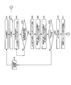
- FIG. 7 shows an example of the confirmation and adjustment processing of the UAT signal.
- the process of FIG. 7 is performed between the portable station device 101 and the communication satellite 103, and is stored in advance in the control unit 301 of the automatic acquisition control unit 209 of the portable station device 101 shown in FIG. Is executed by.
- step S101 the operator of the portable station device 101 completes the adjustment of the antenna direction.
- the satellite communication system 100 according to the present embodiment is mainly a technique related to UAT performed after the antenna direction adjustment is completed, a detailed description of the antenna direction adjustment method will be omitted, but for example, the automatic acquisition control unit 209.
- the control unit 301 is the target communication satellite 103 stored in the satellite DB 306 based on the installation location (latitude and longitude) of the ANT 200 acquired from the position sensor 303 and the current azimuth angle of the ANT 200 acquired from the azimuth sensor 302.
- the three directions of the azimuth, elevation, and polarization angle of the ANT200 to be installed are calculated so as to be in the direction (longitudinal) of, and the direction of the ANT200 is adjusted by the antenna driving unit 208.
- step S102 the control unit 301 of the portable station device 101 starts UAT.
- step S103 the control unit 301 refers to the satellite DB 306, outputs CW from MODEM 207 at a predetermined frequency of the UAT signal, and outputs V from BUC 203 to the communication satellite 103 at a predetermined level lower than the specified level.
- a polarized UAT signal is transmitted (transmission processing).
- the communication satellite 103 frequency-converts the UAT signal transmitted from the portable station device 101, turns it back, and transmits it to the ground. At the time of folding back, the UAT signal is converted from V-polarized wave to H-polarized wave.
- step S104 the control unit 301 receives the UAT signal of H polarization in the facing direction received from the communication satellite 103 in the return direction by the MON-H304 (reception processing), and the frequency of the UAT signal is predetermined. It is determined whether or not it is a frequency, and if the reception of the UAT signal at the specified frequency can be confirmed, the process proceeds to step S105, and if it cannot be confirmed, the process returns to step S103 and the same process is repeated until the UAT signal can be confirmed. .. If the UAT signal cannot be confirmed for a certain period of time, an error notification may be sent to the operator.
- step S105 the control unit 301 controls the BUC 203 to raise the UAT signal to a specified level and transmit it to the communication satellite 103.
- step S106 the portable station device 101 measures the reception level Cd of the H-polarized UAT signal in the opposite direction of the UAT signal received from the communication satellite 103 in the return direction.
- step S107 the control unit 301 receives the leakage level of the UAT signal received from the communication satellite 103 in the reverse direction to the V polarization in the reverse direction by the MON-V305, and measures the leakage level Cx.
- step S108 the control unit 301 calculates the cross polarization discrimination degree XPD according to the equation (1).
- XPD Cd-Cx ... (1)
- the control unit 301 determines whether or not the cross polarization discrimination degree XPD is equal to or higher than a predetermined threshold value (for example, XPD ⁇ 25 dB), and if XPD ⁇ 25 dB, the process proceeds to step S110, and XPD ⁇ In the case of 25 dB, it is determined that the adjustment of the antenna direction is incomplete, and the process proceeds to step S109 (control process).
- a predetermined threshold value for example, XPD ⁇ 25 dB
- step S109 the control unit 301 determines that the adjustment of the antenna direction is incomplete in step S108, so the antenna direction is readjusted, and the process returns to step S101 to execute the same process.
- step S110 the control unit 301 controls MODEM207 and BUC203 to stop the transmission of the UAT signal (wave stop).
- step S111 the control unit 301 confirms with the MON-H304 that the UAT signal received from the communication satellite 103 in return has stopped, and proceeds to the process of (A).
- the portable station device 101 receives the UAT signal transmitted by the portable station device 101 itself by returning the communication satellite 103 even when UAT with the satellite communication carrier cannot be performed. , It is possible to confirm the adjustment of the transmission level and the polarization as in the case of a normal UAT. Here, since the portable station device 101 has completed the confirmation of the UAT signal, the control signal confirmation process is performed next.
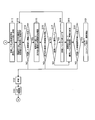
- FIG. 8 shows an example of the confirmation and adjustment processing of the control signal.
- the process of FIG. 8 is performed between the portable station device 101 and the communication satellite 103, and is stored in advance in the control unit 301 of the automatic acquisition control unit 209 of the portable station device 101 shown in FIG. Is executed by.
- the control unit 301 refers to the satellite DB 306, outputs a control signal (CSCO signal) previously applied to the satellite operator from the MODEM 207, and outputs a predetermined level lower than the operation level from the BUC 203 (a predetermined level (CSCO signal)).
- CSCO signal control signal
- the signal is transmitted to the communication satellite 103 in V polarization (transmission processing) at a level 10 dB lower than the operation level).
- the communication satellite 103 frequency-converts the control signal transmitted from the portable station device 101, turns it back, and transmits it to the ground. At the time of turning back, the control signal is converted from V-polarized light to H-polarized wave.
- step S113 the control unit 301 receives the control signal of H polarization in the facing direction received from the communication satellite 103 in the return direction by the MON-H304 (reception processing), and the frequency (center frequency) and band of the control signal. To measure.
- step S114 the control unit 301 determines whether or not the frequency and band of the control signal measured in step S113 match the information (specified value) of the control signal applied to the satellite operator, and if they match. If yes, the process proceeds to step S115, and if they do not match, the process proceeds to step S122 (control process).
- step S115 the control unit 301 measures the leakage level of the H polarization in the front direction to the V polarization in the opposite direction included in the signal received by the MON-H 304 from the communication satellite 103 in the return direction.
- the V polarization control signal is not measured, but if the polarization adjustment is not performed accurately, the V polarization control signal is generated. It is measured.
- step S116 the control unit 301 determines the presence or absence of the V polarization control signal in the reverse direction measured in step S115, and if there is no V polarization control signal, proceeds to the process of step S117 and proceeds to the process of V polarization. If there is a control signal, the process proceeds to step S122. If the level of the V-polarization control signal to be measured is less than a preset threshold value, it may be determined that there is no V-polarization control signal.
- step S117 the control unit 301 determines whether or not the transmission level of the control signal being transmitted is lower than the operation level, and if the transmission level is less than the operation level, proceeds to the process of step S118, and the transmission level ⁇ . If it is an operation level, the process proceeds to step S119 (control process).
- step S118 the control unit 301 controls the BUC 203 to raise the transmission level of the control signal by 2 dB and transmits it to the communication satellite 103, and returns to the process of step S113.
- step S119 the control unit 301 receives the control signal of H polarization in the facing direction received from the communication satellite 103 in the return direction by the MON-H304, and receives the frequency (center frequency) and band of the operation level control signal. Make a measurement.
- step S120 the control unit 301 determines whether or not the frequency and band of the operation level control signal measured in step S119 match the information (specified value) of the control signal applied to the satellite operator. If they match, the process proceeds to step S121, and if they do not match, the process proceeds to step S122 (control process).
- step S121 the control unit 301 completes the UAT started in step S102 of FIG. 7, and obtains each measured value of the UAT signal measured in steps S106, S107, and S108 and each measured value of the control signal measured in step S119.
- the evidence of UAT is saved in the satellite DB 306 and the operation is started (control processing).
- step S122 when the control unit 301 determines NO in steps S114, S116 and S120, it controls MODEM207 and BUC203 to stop the transmission of the control signal (wave stop).
- step S123 the control unit 301 confirms with the MON-H304 that the control signal received from the communication satellite 103 in return has stopped, and returns to the process (B) of FIG. 7 in order to re-execute the UAT.
- the portable station device 101 returns the UAT signal and the control signal transmitted by the portable station device 101 itself to the communication satellite 103 even when UAT with the satellite communication operator cannot be performed.
- the portable station device 101 according to the present embodiment gradually raises the transmission level of the control signal by 2 dB while confirming whether or not it matches the control signal information applied to the satellite operator. Operation can be started without affecting satellite communication users. Further, in the present embodiment, it is possible to measure both V-polarized light and H-polarized light by turning back the communication satellite 103, and confirm that the polarization in the opposite direction (back-polarized light) is not affected. can.
- the program corresponding to the processing described with reference to FIGS. 7 and 8 may be executed on the computer.
- the program may be recorded on a storage medium and provided, or may be provided through a network.
- the transmission radio wave confirmation method, the portable station device, and the transmission radio wave confirmation program in the satellite communication system according to the present invention can be performed by the portable station even when UAT with the satellite communication carrier cannot be performed.
- the UAT can be completed by receiving the UAT signal transmitted by the device by satellite loopback and confirming it.
Landscapes
- Engineering & Computer Science (AREA)
- Computer Networks & Wireless Communication (AREA)
- Signal Processing (AREA)
- Physics & Mathematics (AREA)
- Astronomy & Astrophysics (AREA)
- Aviation & Aerospace Engineering (AREA)
- General Physics & Mathematics (AREA)
- Radio Relay Systems (AREA)
- Mobile Radio Communication Systems (AREA)
Priority Applications (4)
| Application Number | Priority Date | Filing Date | Title |
|---|---|---|---|
| PCT/JP2020/014704 WO2021199217A1 (ja) | 2020-03-30 | 2020-03-30 | 衛星通信システムにおける送信電波確認方法、可搬局装置および送信電波確認プログラム |
| PCT/JP2020/027877 WO2021199452A1 (ja) | 2020-03-30 | 2020-07-17 | 衛星通信システムにおける送信電波確認方法、可搬局装置および送信電波確認プログラム |
| US17/915,816 US20230155671A1 (en) | 2020-03-30 | 2020-07-17 | Transmitting radio wave confirmation method, mobile station device and transmitting radio wave confirmation program in satellite communication system |
| JP2022511498A JP7287576B2 (ja) | 2020-03-30 | 2020-07-17 | 衛星通信システムにおける送信電波確認方法、可搬局装置および送信電波確認プログラム |
Applications Claiming Priority (1)
| Application Number | Priority Date | Filing Date | Title |
|---|---|---|---|
| PCT/JP2020/014704 WO2021199217A1 (ja) | 2020-03-30 | 2020-03-30 | 衛星通信システムにおける送信電波確認方法、可搬局装置および送信電波確認プログラム |
Publications (1)
| Publication Number | Publication Date |
|---|---|
| WO2021199217A1 true WO2021199217A1 (ja) | 2021-10-07 |
Family
ID=77927886
Family Applications (2)
| Application Number | Title | Priority Date | Filing Date |
|---|---|---|---|
| PCT/JP2020/014704 Ceased WO2021199217A1 (ja) | 2020-03-30 | 2020-03-30 | 衛星通信システムにおける送信電波確認方法、可搬局装置および送信電波確認プログラム |
| PCT/JP2020/027877 Ceased WO2021199452A1 (ja) | 2020-03-30 | 2020-07-17 | 衛星通信システムにおける送信電波確認方法、可搬局装置および送信電波確認プログラム |
Family Applications After (1)
| Application Number | Title | Priority Date | Filing Date |
|---|---|---|---|
| PCT/JP2020/027877 Ceased WO2021199452A1 (ja) | 2020-03-30 | 2020-07-17 | 衛星通信システムにおける送信電波確認方法、可搬局装置および送信電波確認プログラム |
Country Status (3)
| Country | Link |
|---|---|
| US (1) | US20230155671A1 (https=) |
| JP (1) | JP7287576B2 (https=) |
| WO (2) | WO2021199217A1 (https=) |
Families Citing this family (3)
| Publication number | Priority date | Publication date | Assignee | Title |
|---|---|---|---|---|
| DE112022004351T5 (de) | 2021-09-10 | 2024-06-27 | Zhejiang Dunan Artificial Environment Co., Ltd. | Magnetventil |
| JP2023122242A (ja) * | 2022-02-22 | 2023-09-01 | 株式会社東芝 | 移動局装置、制御方法、および衛星通信システム |
| DE102022207803A1 (de) * | 2022-07-28 | 2024-02-08 | Robert Bosch Gesellschaft mit beschränkter Haftung | Radarsensorvorrichtung und Verfahren zur Selbstprüfung |
Citations (7)
| Publication number | Priority date | Publication date | Assignee | Title |
|---|---|---|---|---|
| JPS5884547A (ja) * | 1981-11-16 | 1983-05-20 | Nec Corp | 衛星通信地球局送信電力制御方式 |
| JPS6442931A (en) * | 1987-08-10 | 1989-02-15 | Fujitsu Ltd | Transmission power control system for satellite communication earth station |
| JPH0244928A (ja) * | 1988-08-05 | 1990-02-14 | Nec Corp | 衛星通信地球局送信電力制御方式 |
| JPH02143616A (ja) * | 1988-11-24 | 1990-06-01 | Nec Corp | 地球局送信電力制御方式 |
| JPH0522204A (ja) * | 1991-07-10 | 1993-01-29 | Nec Corp | 移動型衛星通信地球局の回線設定システム |
| JPH10327103A (ja) * | 1997-05-23 | 1998-12-08 | Nec Corp | 送信電力制御方式 |
| JP2010268377A (ja) * | 2009-05-18 | 2010-11-25 | Mitsubishi Electric Corp | 衛星通信システム |
Family Cites Families (5)
| Publication number | Priority date | Publication date | Assignee | Title |
|---|---|---|---|---|
| US5257872A (en) * | 1992-05-05 | 1993-11-02 | Hughes Aircraft Company | High power waveguide switch and method |
| JP2590706B2 (ja) * | 1993-09-27 | 1997-03-12 | 日本電気株式会社 | 衛星通信地球局アンテナの交差偏波調整装置 |
| CA2349170A1 (en) * | 1998-11-09 | 2000-05-18 | Qualcomm Incorporated | Method and apparatus for cross polarized isolation in a communication system |
| US6233433B1 (en) * | 1999-02-04 | 2001-05-15 | The Boeing Company | Apparatus and method of testing multi-beam satellite repeater in-orbit from a single ground station using a sampling and combining matrix |
| JP5872594B2 (ja) * | 2014-01-08 | 2016-03-01 | 株式会社東芝 | 衛星通信システム、およびアンテナ調整方法 |
-
2020
- 2020-03-30 WO PCT/JP2020/014704 patent/WO2021199217A1/ja not_active Ceased
- 2020-07-17 JP JP2022511498A patent/JP7287576B2/ja active Active
- 2020-07-17 WO PCT/JP2020/027877 patent/WO2021199452A1/ja not_active Ceased
- 2020-07-17 US US17/915,816 patent/US20230155671A1/en not_active Abandoned
Patent Citations (7)
| Publication number | Priority date | Publication date | Assignee | Title |
|---|---|---|---|---|
| JPS5884547A (ja) * | 1981-11-16 | 1983-05-20 | Nec Corp | 衛星通信地球局送信電力制御方式 |
| JPS6442931A (en) * | 1987-08-10 | 1989-02-15 | Fujitsu Ltd | Transmission power control system for satellite communication earth station |
| JPH0244928A (ja) * | 1988-08-05 | 1990-02-14 | Nec Corp | 衛星通信地球局送信電力制御方式 |
| JPH02143616A (ja) * | 1988-11-24 | 1990-06-01 | Nec Corp | 地球局送信電力制御方式 |
| JPH0522204A (ja) * | 1991-07-10 | 1993-01-29 | Nec Corp | 移動型衛星通信地球局の回線設定システム |
| JPH10327103A (ja) * | 1997-05-23 | 1998-12-08 | Nec Corp | 送信電力制御方式 |
| JP2010268377A (ja) * | 2009-05-18 | 2010-11-25 | Mitsubishi Electric Corp | 衛星通信システム |
Also Published As
| Publication number | Publication date |
|---|---|
| JP7287576B2 (ja) | 2023-06-06 |
| WO2021199452A1 (ja) | 2021-10-07 |
| US20230155671A1 (en) | 2023-05-18 |
| JPWO2021199452A1 (https=) | 2021-10-07 |
Similar Documents
| Publication | Publication Date | Title |
|---|---|---|
| JP7318806B2 (ja) | 衛星通信システムにおけるアンテナ方向調整方法、可搬局装置およびアンテナ方向調整プログラム | |
| JP6412294B1 (ja) | コンパスなしでのleo衛星の獲得 | |
| CN101180551B (zh) | 天线阵列校准系统及方法 | |
| JP2901170B2 (ja) | 衛星/陸上移動体通信システム統合方式 | |
| AU731834B2 (en) | Wireless communication device and system incorporating location-determining means | |
| KR101822369B1 (ko) | 고용량 하이브리드 지상/위성 셀룰러 무선 통신 시스템 | |
| JP7287576B2 (ja) | 衛星通信システムにおける送信電波確認方法、可搬局装置および送信電波確認プログラム | |
| JPH0629916A (ja) | 位置割り出しトランシーバ | |
| US6647244B1 (en) | Wireless vehicular repeater system | |
| EP2868133A1 (en) | Terrestrial communications network suitable for providing air-to-ground connectivity | |
| US20210006327A1 (en) | Method and apparatus for establishing communications with a satellite | |
| EP0996241B1 (en) | Mobile communication system | |
| US20030083008A1 (en) | Method and system for identifying repeater traffic in a code divsion multiple access system | |
| JP7435769B2 (ja) | 衛星通信システムにおけるアンテナ方向調整方法、可搬局装置およびアンテナ方向調整プログラム | |
| US4809006A (en) | Satellite communications using the telemetry tracking and control system | |
| JP3109311B2 (ja) | 無線送受信装置及び移動通信システム | |
| KR20020005312A (ko) | 멀티채널 중계기 | |
| JP3226455B2 (ja) | 無線通信路リンクアップシステム | |
| US20240405858A1 (en) | Mitigating interference between satellite and terrestrial cellular networks | |
| WO2024252489A1 (ja) | 無線通信システム、無線局、無線通信方法、および無線通信用プログラム | |
| WO2025131225A1 (en) | Establishing device-to-device (d2d) communications using local-area repeaters | |
| JPS6399627A (ja) | Mca中継制御方式 | |
| CN120826929A (zh) | Ta的确定方法、装置、设备及存储介质 | |
| JPS6313377B2 (https=) | ||
| MXPA99007714A (en) | Wireless communication device and system incorporating location-determining means |
Legal Events
| Date | Code | Title | Description |
|---|---|---|---|
| 121 | Ep: the epo has been informed by wipo that ep was designated in this application |
Ref document number: 20928531 Country of ref document: EP Kind code of ref document: A1 |
|
| NENP | Non-entry into the national phase |
Ref country code: DE |
|
| 122 | Ep: pct application non-entry in european phase |
Ref document number: 20928531 Country of ref document: EP Kind code of ref document: A1 |
|
| NENP | Non-entry into the national phase |
Ref country code: JP |