WO2021193902A1 - 体液採取装置 - Google Patents
体液採取装置 Download PDFInfo
- Publication number
- WO2021193902A1 WO2021193902A1 PCT/JP2021/012790 JP2021012790W WO2021193902A1 WO 2021193902 A1 WO2021193902 A1 WO 2021193902A1 JP 2021012790 W JP2021012790 W JP 2021012790W WO 2021193902 A1 WO2021193902 A1 WO 2021193902A1
- Authority
- WO
- WIPO (PCT)
- Prior art keywords
- needle
- capillary
- body fluid
- needle tube
- collecting device
- Prior art date
- Legal status (The legal status is an assumption and is not a legal conclusion. Google has not performed a legal analysis and makes no representation as to the accuracy of the status listed.)
- Ceased
Links
Images


Classifications
-
- A—HUMAN NECESSITIES
- A61—MEDICAL OR VETERINARY SCIENCE; HYGIENE
- A61B—DIAGNOSIS; SURGERY; IDENTIFICATION
- A61B10/00—Instruments for taking body samples for diagnostic purposes; Other methods or instruments for diagnosis, e.g. for vaccination diagnosis, sex determination or ovulation-period determination; Throat striking implements
- A61B10/0045—Devices for taking samples of body liquids
-
- A—HUMAN NECESSITIES
- A61—MEDICAL OR VETERINARY SCIENCE; HYGIENE
- A61B—DIAGNOSIS; SURGERY; IDENTIFICATION
- A61B10/00—Instruments for taking body samples for diagnostic purposes; Other methods or instruments for diagnosis, e.g. for vaccination diagnosis, sex determination or ovulation-period determination; Throat striking implements
-
- A—HUMAN NECESSITIES
- A61—MEDICAL OR VETERINARY SCIENCE; HYGIENE
- A61B—DIAGNOSIS; SURGERY; IDENTIFICATION
- A61B3/00—Apparatus for testing the eyes; Instruments for examining the eyes
- A61B3/10—Objective types, i.e. instruments for examining the eyes independent of the patients' perceptions or reactions
-
- A—HUMAN NECESSITIES
- A61—MEDICAL OR VETERINARY SCIENCE; HYGIENE
- A61B—DIAGNOSIS; SURGERY; IDENTIFICATION
- A61B5/00—Measuring for diagnostic purposes; Identification of persons
- A61B5/15—Devices for taking samples of blood
- A61B5/150007—Details
- A61B5/150015—Source of blood
- A61B5/15003—Source of blood for venous or arterial blood
-
- A—HUMAN NECESSITIES
- A61—MEDICAL OR VETERINARY SCIENCE; HYGIENE
- A61B—DIAGNOSIS; SURGERY; IDENTIFICATION
- A61B5/00—Measuring for diagnostic purposes; Identification of persons
- A61B5/15—Devices for taking samples of blood
- A61B5/150007—Details
- A61B5/150053—Details for enhanced collection of blood or interstitial fluid at the sample site, e.g. by applying compression, heat, vibration, ultrasound, suction or vacuum to tissue; for reduction of pain or discomfort; Skin piercing elements, e.g. blades, needles, lancets or canulas, with adjustable piercing speed
- A61B5/150106—Means for reducing pain or discomfort applied before puncturing; desensitising the skin at the location where body is to be pierced
-
- A—HUMAN NECESSITIES
- A61—MEDICAL OR VETERINARY SCIENCE; HYGIENE
- A61B—DIAGNOSIS; SURGERY; IDENTIFICATION
- A61B5/00—Measuring for diagnostic purposes; Identification of persons
- A61B5/15—Devices for taking samples of blood
- A61B5/150007—Details
- A61B5/150374—Details of piercing elements or protective means for preventing accidental injuries by such piercing elements
- A61B5/150381—Design of piercing elements
- A61B5/150389—Hollow piercing elements, e.g. canulas, needles, for piercing the skin
- A61B5/150396—Specific tip design, e.g. for improved penetration characteristics
-
- A—HUMAN NECESSITIES
- A61—MEDICAL OR VETERINARY SCIENCE; HYGIENE
- A61B—DIAGNOSIS; SURGERY; IDENTIFICATION
- A61B5/00—Measuring for diagnostic purposes; Identification of persons
- A61B5/15—Devices for taking samples of blood
- A61B5/150007—Details
- A61B5/150374—Details of piercing elements or protective means for preventing accidental injuries by such piercing elements
- A61B5/150381—Design of piercing elements
- A61B5/150473—Double-ended needles, e.g. used with pre-evacuated sampling tubes
-
- A—HUMAN NECESSITIES
- A61—MEDICAL OR VETERINARY SCIENCE; HYGIENE
- A61B—DIAGNOSIS; SURGERY; IDENTIFICATION
- A61B5/00—Measuring for diagnostic purposes; Identification of persons
- A61B5/15—Devices for taking samples of blood
- A61B5/150007—Details
- A61B5/150732—Needle holders, for instance for holding the needle by the hub, used for example with double-ended needle and pre-evacuated tube
-
- A—HUMAN NECESSITIES
- A61—MEDICAL OR VETERINARY SCIENCE; HYGIENE
- A61B—DIAGNOSIS; SURGERY; IDENTIFICATION
- A61B5/00—Measuring for diagnostic purposes; Identification of persons
- A61B5/15—Devices for taking samples of blood
- A61B5/150007—Details
- A61B5/150946—Means for varying, regulating, indicating or limiting the speed or time of blood collection
-
- A—HUMAN NECESSITIES
- A61—MEDICAL OR VETERINARY SCIENCE; HYGIENE
- A61B—DIAGNOSIS; SURGERY; IDENTIFICATION
- A61B5/00—Measuring for diagnostic purposes; Identification of persons
- A61B5/15—Devices for taking samples of blood
- A61B5/153—Devices specially adapted for taking samples of venous or arterial blood, e.g. with syringes
-
- A—HUMAN NECESSITIES
- A61—MEDICAL OR VETERINARY SCIENCE; HYGIENE
- A61B—DIAGNOSIS; SURGERY; IDENTIFICATION
- A61B5/00—Measuring for diagnostic purposes; Identification of persons
- A61B5/15—Devices for taking samples of blood
- A61B5/150007—Details
- A61B5/150015—Source of blood
- A61B5/150022—Source of blood for capillary blood or interstitial fluid
Definitions
- the present invention relates to a body fluid collecting device and a method for collecting body fluid using the body fluid collecting device.
- Patent Document 1 describes a conventional body fluid collecting device.
- the body fluid collecting device described in Patent Document 1 is composed of a syringe.
- the body fluid is drawn into the cylinder body by inserting an injection needle into a living body and pulling a piston.
- An object of the present invention is to provide a body fluid collecting device capable of collecting a certain amount of body fluid while minimizing damage to the living body, a method for collecting body fluid using the device, and a method for collecting aqueous humor.
- the following body fluid collecting device is provided.
- a needle part having a needle tube with a needle tip formed on it, A capillary that is removably connected to the base end on the side opposite to the needle tip in the longitudinal direction of the needle tube.
- a body fluid collecting device equipped with.
- the needle portion has a holding portion that contacts the outer peripheral surface of the needle tube and holds the needle tube.
- the base end portion of the needle tube projects from the holding portion in the longitudinal direction of the needle tube.
- Item 1 The body fluid collecting device according to Item 1-1, wherein the capillary is connected to the base end portion in a state of being fitted to the base end portion.
- Item 1-3 The body fluid collecting device according to Item 1-2, wherein the protrusion dimension of the base end portion from the holding portion is 1 mm or more and 13 mm or less.
- Item 1-4 The body fluid collecting device according to Item 1-2 or Item 1-3, wherein the inner diameter of the capillary is the same as the outer diameter of the base end portion.
- Item 1-5 The body fluid collecting device according to any one of Items 1-1 to 1-4, wherein the outer diameter of the needle tube is 0.18 mm or more and 0.30 mm or less.
- the needle portion has a needle base that supports the needle tube, and has a needle base.
- the needle base is A holding portion that contacts the outer peripheral surface of the needle tube and holds the needle tube, A cylindrical portion connected to the holding portion and into which the capillary is removably fitted, Have, Item 16.
- the needle portion has a needle base that supports the needle tube, and has a needle base.
- the needle base is A holding portion that contacts the outer peripheral surface of the needle tube and holds the needle tube,
- the tubular part connected to the holding part and A holding member arranged in the cylindrical portion and holding the capillary so as to be removable, Have, Item 1.
- the needle portion has a needle base that supports the needle tube, and has a needle base.
- Item 2 The body fluid collecting device according to any one of Items 1-1 to 1-7, wherein the body fluid collecting device further includes a protective member attached to the needle base and covering the periphery of the capillary.
- a needle part having a needle tube with a needle tip formed on it, A capillary that is removably connected to the base end on the side opposite to the needle tip in the longitudinal direction of the needle tube.
- the needle portion has a holding portion that contacts the outer peripheral surface of the needle tube and holds the needle tube.
- the base end portion of the needle tube projects from the holding portion in the longitudinal direction of the needle tube.
- the capillary is connected to the base end portion in a state of being fitted to the base end portion.
- the protruding dimension of the base end portion from the holding portion is 1 mm or more and 13 mm or less.
- the inner diameter of the capillary is the same as the outer diameter of the base end portion.
- the outer diameter of the needle tube is 0.18 mm or more and 0.30 mm or less.
- the needle portion has a needle base that supports the needle tube, and has a needle base.
- a protective member attached to the needle base and covering the periphery of the capillary is further provided.
- Body fluid collection device is further provided.
- Item 2-1 A method for collecting body fluid using the body fluid collecting device according to any one of Items 1-1 to 1-9.
- Item 2-2 A method for collecting body fluid using the body fluid collecting device according to Item 1-9.
- the following method for collecting aqueous humor is provided.
- Item 3-1 A method for collecting aqueous humor using the body fluid collecting device according to any one of Items 1-1 to 1-9.
- Item 3-2 A method for collecting aqueous humor using the body fluid collecting device according to Item 1-9.
- the body fluid collecting device of the above aspect according to the present invention, the body fluid collecting method using the body fluid collecting method, and the aqueous humor collecting method have an advantage that a certain amount of body fluid can be collected while minimizing damage to the living body. There is.
- FIG. 1 is a cross-sectional view of a body fluid collecting device according to an embodiment of the present invention in a plane along the longitudinal direction of a needle tube.
- FIG. 2 is an exploded perspective view of the body fluid collecting device of the same as above.
- FIG. 3 is an explanatory diagram for explaining the second step of the method of collecting aqueous humor using the same body fluid collecting device.
- 4 (A) and 4 (B) are explanatory views for explaining the third step of the method of collecting aqueous humor using the same body fluid collecting device.
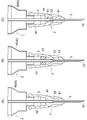
- FIG. 5A is a cross-sectional view of the body fluid collecting device according to the first modification in the plane along the longitudinal direction of the needle tube.
- FIG. 5B is a cross-sectional view of the body fluid collecting device according to the second modification in the plane along the longitudinal direction of the needle tube.
- FIG. 5C is a cross-sectional view of the body fluid collecting device according to the third modification in the plane along the longitudinal direction of the needle tube.
- FIG. 6 is a graph showing the measurement results of the examples.
- the body fluid collecting device 1 is a device that collects a certain amount of body fluid from a living body.
- living body includes animals including mammals, and the mammals include, for example, humans, monkeys, pigs, dogs, cats, rabbits, guinea pigs, rats, mice and the like.
- the body fluid collecting device 1 according to the present embodiment may be used for any test, examination, diagnosis, etc., for example, may be used for a non-clinical (preclinical) test, or may be used for a clinical test. ..
- the "body fluid” is preferably a body fluid that can be inspected by collecting a small amount and a fixed amount, but there is no particular limitation.
- body fluids examples include aqueous humor 73 (aqueous humor), blood, cerebrospinal fluid (cerebrospinal fluid), lymph, body cavity fluid (chest water, ascites, etc.), digestive juice (gastric juice, bile, pancreatic juice, intestinal juice, etc.).
- aqueous humor 73 aqueous humor
- blood cerebrospinal fluid
- cerebrospinal fluid Cerebrospinal fluid
- lymph body cavity fluid
- body cavity fluid chest water, ascites, etc.
- digestive juice gastric juice, bile, pancreatic juice, intestinal juice, etc.
- the body fluid collecting device 1 can collect a small amount and a certain amount of aqueous humor 73 from an animal as a living body. By inspecting the collected aqueous humor 73, for example, the drug concentration, the biological component concentration, and the like contained in the aqueous humor 73 can be evaluated. According to the body fluid collecting device 1 according to the present embodiment, since only a small amount of aqueous humor 73 required for the examination is collected, the aqueous humor 73 can be repeatedly collected from one living body over time. Therefore, if the body fluid collecting device 1 according to the present embodiment is used, it is possible to acquire data over time for each individual living body, and there is an advantage that an error in data interpretation due to variation among individuals can be avoided.
- the collected amount can be minimized.
- the body fluid collecting device 1 according to the present embodiment since the capillary phenomenon is used for collecting, it is not necessary to pull the plunger as in the past, the workability can be improved, and the plunger can be pulled.
- the damage caused by the negative pressure to the living body can be removed, this also contributes to the minimization of the damage to the living body.
- the body fluid collecting device 1 according to the present embodiment it is possible to reduce the damage to the living body and minimize the damage to the living body even in the case of collecting the body fluid once as in the conventional case.
- body fluid can be repeatedly collected from one living body over time.
- the body fluid collecting device 1 includes a needle portion 2 having a needle tube 3 and a capillary 5.
- the needle tube 3 has a needle tip 32 that is inserted into a target site of a living body.
- the capillary 5 is removably connected to the end portion of the needle tube 3 in the longitudinal direction opposite to the needle tip 32 (hereinafter, referred to as “base end portion 33”).
- the aqueous humor 73 is drawn into the needle tube 3 by the action of the capillary phenomenon, and then the aqueous humor 73 It leads to Capillary 5.
- the aqueous humor 73 that has reached the capillary 5 moves in the capillary 5 toward the end opposite to the needle tube 3 in the longitudinal direction due to the action of the capillary phenomenon, and fills the inside of the capillary 5.
- the user removes the capillary 5 from the needle tube 3 and takes out the aqueous humor 73 filled in the capillary 5.
- the body fluid collecting device 1 since the amount of body fluid filled in the capillary 5 is always constant according to the volume of the capillary 5, according to the body fluid collecting device 1, a constant amount of body fluid collected from the living body is directly used for the examination. be able to.
- the term "directly” as used herein means that the entire amount of the body fluid filled in the capillary 5 is used as it is for the test. It does not include using the amount for testing.
- the body fluid collecting device 1 includes a needle portion 2, a capillary 5, and a protective member 6.
- the body fluid collecting device 1 is not equipped with a protector that protects the needle tip 32, but the body fluid collecting device 1 according to the present invention may be provided with a protector.
- Needle part 2 is a part having a needle tube 3.
- the needle portion 2 is composed of, for example, an injection needle, and is detachably attached to the protective member 6.
- the needle portion 2 includes a needle tube 3 and a needle base 4.
- the needle tube 3 is a part where one tip is pierced into a living body.
- the needle tube 3 is composed of a thin tube formed in a straight line.
- the tip (needle tip 32) of the needle tube 3 is cut along a surface inclined with respect to the axial direction (longitudinal direction) of the needle tube 3.
- the shape of the needle tip 32 is not particularly limited, and examples thereof include a single point, a hoover point, a lancet point, and a back cut point.
- a flow path 31 through which a body fluid passes is formed inside the needle tube 3.
- the flow path 31 is continuous from one end to the other end along the longitudinal direction of the needle tube 3.
- the material of the needle tube 3 is not particularly limited, and examples thereof include stainless steel, stainless steel (for example, SUS304, SUS316L, etc.), aluminum alloy, titanium, titanium alloy, synthetic resin, and the like.
- the outer diameter of the needle tube 3 is preferably, for example, 0.18 mm or more and 0.30 mm or less, and more preferably 0.18 mm, from the viewpoint of collecting the aqueous humor 73 of the living body.
- the outer diameter of the needle tube 3 exceeds 0.30 mm, the cornea 71 of the living body is significantly damaged, and the burden on the living body is increased.
- the outer diameter of the needle tube 3 is not particularly limited because an appropriate size differs depending on the type and size of the living body or the collection site of the body fluid.
- the needle base 4 is a part that supports the needle tube 3.
- the needle base 4 may function as a portion directly held by the user while supporting the needle tube 3, but it may be attached to the protective member 6 to fix the needle tube 3 to the protective member 6.
- the shape of the needle base 4 can be selected according to the shape of the tip portion 61 of the protective member 6, and may be, for example, a standard type such as a screw type or a luer lock type.
- the material of the needle base 4 is not particularly limited, and examples thereof include synthetic resin and metal. As shown in FIG. 1, the needle base 4 includes a holding portion 41 and a tubular portion 42.
- the holding portion 41 is a portion that contacts the outer peripheral surface of the needle tube 3 and holds the needle tube 3. Holding of the needle tube 3 to the holding portion 41 is realized by, for example, fitting, screwing, adhesion, welding, welding, insert molding, two-color molding and the like.
- the holding portion 41 holds an intermediate portion in the longitudinal direction of the needle tube 3. That is, in the needle tube 3, the end portion on the side opposite to the needle tip 32 is not held by the holding portion 41 and protrudes from the holding portion 41.
- the portion protruding from the holding portion 41 is defined as the “base end portion 33”.
- the dimension of the base end portion 33 of the needle tube 3 (hereinafter, may be referred to as “protruding dimension L1”) is preferably 1 mm or more and 13 mm or less, and more preferably 4 mm or more and 6 mm or less. If the protruding dimension of the base end portion 33 is less than 1 mm, the capillary 5 described later cannot be properly supported, which is not preferable.
- the end of the base end portion 33 may protrude from the tubular portion 42, and the base end portion 33 of the needle tube 3 is damaged during transportation or use. there is a possibility. That is, it is preferable that the base end portion 33 of the needle tube 3 fits in the tubular portion 42.
- the tubular portion 42 is a portion extending in a cylindrical shape from the holding portion 41, and the inner diameter thereof is formed to be larger than the inner diameter of the holding portion 41.
- the tubular portion 42 preferably covers the periphery of the connecting portion between the needle tube 3 and the capillary 5. The user can collect the body fluid without attaching the protective member 6 by holding the tubular portion 42, but in the present embodiment, the user holds the protective member 6 attached to the tubular portion 42 and collects the body fluid. Can be collected.
- the tubular portion 42 is integrally formed from the end portion of the holding portion 41 on the proximal end portion 33 side of the needle tube 3 in the longitudinal direction.
- the tubular portion 42 is formed in a cylindrical shape, and a gap is interposed between the tubular portion 42 and the proximal end portion 33 of the needle tube 3 (that is, it is separated from the proximal end portion 33).
- the tip portion 61 of the protective member 6 is fitted into the open end of the tubular portion 42, whereby the tubular portion 42 is attached to the tip portion 61 of the protective member 6.
- the open end of the tubular portion 42 is formed in a brim shape, and when the needle portion 2 is attached to the protective member 6, it faces the end surface (tip surface 63) of the protective member 6 in the longitudinal direction.
- the open end of the cylindrical portion 42 and the tip surface 63 of the protective member 6 may have a gap or may be in contact with each other.
- the capillary 5 is removably connected to the proximal end 33 of the needle tube 3.
- a liquid body fluid
- the liquid permeates due to the action of the capillary phenomenon, and the liquid level of the liquid advances toward the other end in the longitudinal direction.
- the dimension (length dimension) in the longitudinal direction of the capillary 5 is not particularly limited, but is set according to the capacity of the liquid that can be stored inside the capillary 5 (hereinafter, referred to as "liquid collection capacity").
- the liquid collection capacity of the capillary 5 is 0.25 ⁇ l or more and 200 ⁇ l or less, preferably 5 ⁇ l or more and 50 ⁇ l or less, and more preferably 5 ⁇ l or more and 20 ⁇ l or less.
- the length dimension of the capillary 5 is 30 mm or more and 130 mm or less, preferably 30 mm or more and 100 mm or less, and more preferably 30 mm or more and 70 mm or less.
- the inner diameter of the capillary 5 is 0.1 mm or more and 1.5 mm or less, preferably 0.3 mm or more and 1.0 mm or less, and more preferably 0.5 mm or more and 0.7 mm or less.
- the liquid collection capacity of the capillary 5 is 0.25 ⁇ l, and in this case, the length dimension is 32 mm and the inner diameter is 0.099 mm. As another example, the liquid collection capacity is 10 ⁇ l, and in this case, the length dimension is 41 mm and the inner diameter is 0.56 mm. Further, as another example, the liquid collection capacity is 20 ⁇ l, and in this case, the length dimension is 64 mm and the inner diameter is 0.63 mm.
- the capillary 5 is connected to the base end portion 33 in a state of being fitted to the base end portion 33.
- the term "fitted” as used herein includes a case where the base end portion 33 is fitted into the capillary 5 and a case where the capillary 5 is fitted into the base end portion 33. However, in the present embodiment, the base end portion 33 is fitted in the capillary 5.
- the inner diameter of the capillary 5 is the same as the outer diameter of the base end portion 33. Therefore, the capillary 5 is supported with respect to the base end portion 33 in a state where the base end portion 33 is fitted.
- the overlapping dimension L2 between the capillary 5 and the base end portion 33 in a state where the capillary 5 and the base end portion 33 are fitted is preferably 4 mm or more. When the overlapping dimension L2 between the capillary 5 and the base end portion 33 is 4 mm or more, the capillary 5 can be effectively supported with respect to the base end portion 33.
- the overlapping dimension of the capillary 5 and the base end portion 33 may be less than 1 mm, and the inside of the capillary 5 may be less than 1 mm. As long as the base end portion 33 and the inside of the base end portion 33 are communicated with each other, there may be no overlapping portion.
- the capillary 5 in the present specification does not mean “identical” in a strict sense, but has the effect that the capillary 5 is fitted to the proximal end portion 33 to support the capillary 5. As long as can be obtained, even if it is “substantially the same”, it is in the category of "same".
- the inner diameter of the capillary 5 is smaller than the outer diameter of the base end portion 33 before being fitted, but after being fitted, the inner diameter of the capillary 5 is the same as the inner diameter of the capillary 5.
- the inner diameter of the capillary 5 is “same” as the outer diameter of the base end portion 33. Further, after the body fluid passes through the flow path 31 inside the needle tube 3 by the action of the capillary phenomenon by the needle tube 3, it does not collect inside the tubular portion 42 of the needle base 4, but by the action of the capillary phenomenon by the capillary 5 Even when the particles are continuously collected from the capillary tube 3 into the inside of the capillary 5, they are considered to be “identical”.
- the material of the capillary 5 is not particularly limited, and examples thereof include metal, synthetic resin, carbon, glass, wood, paper, cloth, and rubber. However, considering the workability of the liquid collection, it is preferable that the material has a certain hardness, water repellency, and the like.
- the capillary 5 is detachably attached to the base end portion 33 of the needle tube 3. Therefore, the body fluid that has advanced from the needle tube 3 into the capillary 5 further advances due to the action of the capillary phenomenon, and reaches the end of the capillary 5 in the longitudinal direction opposite to the needle tube 3. Then, since a certain amount of body fluid enters the capillary 5, a certain amount of body fluid can be collected by removing the capillary 5 from the needle tube 3.
- the protective member 6 covers the periphery of the capillary 5 to protect the capillary 5.
- the term "protection” as used herein means protection from external forces from other members, as well as from powders and liquids such as chemicals and solutions, and fine stains such as lint and dust.
- the protective member 6 may have flexibility or rigidity.
- the protective member 6 according to the present embodiment is composed of a rigid syringe 60, and in addition to being able to appropriately protect the capillary 5, the user can hold the syringe 60 to collect liquid. ..
- “covering the periphery” as used herein means surrounding most of the capillary 5 in the longitudinal direction, and a part of the capillary 5 may protrude from the protective member 6.
- the protective member 6 can protect the capillary 5, for example, even if the capillary 5 protrudes from the end of the protective member 6 by about 20% of the whole, it is in the category of "covering the surroundings".
- the syringe 60 will be described as an example of the protective member 6.
- the syringe 60 is equipped with a needle portion 2 to which the capillary 5 is attached, thereby protecting the capillary 5 from damage or the like.
- the syringe 60 has a certain rigidity, and is made of, for example, synthetic resin, metal, glass, acrylic, or the like.
- the term "constant rigidity” as used herein means rigidity to the extent that it can stand on its own, and if it is rigid enough to be elastically deformed, it is in the category of "having a constant rigidity". Since the syringe 60 has a certain rigidity, the user can hold (hold) the syringe 60 to collect the liquid.
- the syringe 60 has a tip portion 61 to which the needle base 4 is attached, and an outer cylinder portion 62 leading to the tip portion 61.
- the outer cylinder portion 62 is a portion of the syringe 60 that covers the periphery of the capillary 5.
- the outer cylinder portion 62 is formed in a cylindrical shape having an opening surface formed on one end surface in the longitudinal direction and a tip surface 63 on the other end surface.
- the inner surface of the outer cylinder portion 62 has a gap between the outer cylinder portion 62 and the capillary 5, and is separated from the capillary 5.
- the outer cylinder portion 62 covers the periphery of the capillary portion 5, but it is preferable that the end of the capillary portion 5 is located in the middle of the outer cylinder portion 62 in the axial direction as in the present embodiment.
- the tip surface 63 of the outer cylinder portion 62 intersects the outer cylinder portion 62 in the longitudinal direction (here, substantially orthogonal to each other).
- the tip portion 61 is a portion to which the needle base 4 is attached, and protrudes from the tip surface 63 of the outer cylinder portion 62 along the longitudinal direction of the outer cylinder portion 62.
- the tip portion 61 is formed in a cylindrical shape. Examples of the shape of the tip portion 61 include a lure slip type, a luer lock type, a luer metal type, and a catheter tip type.
- the tip portion 61 is formed on the central axis of the outer cylinder portion 62, but may be formed at a position deviated from the central axis of the outer cylinder portion 62, for example.
- the capillary 5 is covered by the outer cylinder portion 62. Therefore, in the body fluid collecting device 1 according to the present embodiment, it is possible to prevent the capillary 5 from hitting another member and coming off during the collection of the body fluid. Further, since the user can grasp the outer cylinder portion 62 to collect the liquid, it is possible to improve the ease of holding the body fluid collecting device 1 as compared with the case where the outer cylinder portion 62 is not provided.
- the body fluid collecting device 1 according to the present embodiment can collect various body fluids from various living bodies, but the method of collecting the aqueous humor 73 of an animal will be described below as an example.
- the method for collecting the aqueous humor 73 of the present embodiment includes a first step, a second step, a third step, a fourth step, and a fifth step.
- the first step is the process of preparing before collecting the body fluid.
- a living body for example, a rabbit
- the eyeball 7 of the living body is locally anesthetized.
- "Baoding” here means keeping the living body stationary.
- 0.4% oxybuprocaine hydrochloride ophthalmic solution (Santen Pharmaceutical Co., Ltd. Benokiseal (registered trademark) ophthalmic solution 0.4%) or a diluted solution thereof (diluting medium: physiological saline or artificial tears) Liquid, PBS: Phosphate-buffered saline, etc.)
- PBS Phosphate-buffered saline, etc.
- aqueous humor 73 can be repeatedly collected for one living body at intervals.
- a diluent in order to minimize damage to the cornea 71 due to frequent administration of local anesthesia.
- the surface of the cornea 71 tends to be roughened when the undiluted ophthalmic solution is repeatedly used as the local anesthesia, but this can be reduced by using the diluted solution.
- the effect of local anesthesia is confirmed by stimulating the cornea 71 with a device with a rounded tip, for example, the tip of tweezers, and confirming the disappearance of the corneal reflex.
- the eyelid opener is attached to the living body. The eyelid opener can prevent blinking and keep the living body's eyelids open.
- the second step is a step of inserting the needle tip 32 of the needle tube 3 into the tissue (here, the anterior chamber 72) in which the body fluid of the living body exists.
- the needle tip 32 of the needle tube 3 is punctured into the eyeball 7 with the eyelid open by the eyelid opener by two-step puncture.
- the needle tip 32 of the needle tube 3 is punctured into the cornea 71 in the direction along the normal line, the thickness of the cornea 71 is pushed forward for a while in the direction along the cornea 71, and then the anterior chamber 72 side again. It means that the needle tip 32 is inserted by changing the angle to.
- Reference numeral 74 in FIG. 3 is a crystalline lens
- reference numeral 75 is a vitreous body.
- the third step is a step of extracting the needle tip 32 from the tissue (in the anterior chamber 72) after the capillary 5 is filled with the body fluid (here, the aqueous humor 73).
- the aqueous humor 73 advances in the needle tube 3 due to the action of the capillary phenomenon, and the liquid level reaches the base end. Approaching part 33.
- the aqueous humor 73 reaches the inside of the capillary 5, and the aqueous humor 73 fills the capillary 5 due to the action of the capillary phenomenon.
- FIG. 4B the user confirms that the aqueous humor 73 has reached the end of the capillary 5 opposite to the needle tube 3 side in the longitudinal direction, and then pulls the needle tube 3 from inside the anterior chamber 72. Pull out.
- the direction in which the needle tube 3 is inserted into the anterior chamber 72 is not particularly limited, but it is preferable to keep it as vertical as possible. This is because it is preferable to prevent the capillary 5 from coming off the needle tube 3 as much as possible when the needle tube 3 is inserted into the anterior chamber 72 or while the aqueous humor 73 is being drawn into the needle tube 3 and the capillary 5.
- the fourth step is the step of removing the capillary 5 from the needle tube 3.
- the third step since the inside of the capillary 5 is filled with a certain amount of aqueous humor 73, it is possible to easily collect a certain amount of aqueous humor 73 from the capillary 5 by removing the capillary 5 from the needle tube 3.
- the fifth step is the step of discharging the aqueous humor 73 filled in the capillary 5.
- a certain amount of aqueous humor 73 filled in the capillary 5 is taken out from the inside of the capillary 5, for example, by blowing air into the capillary 5 from one end in the longitudinal direction and pressurizing the inside of the capillary 5. Is done.
- the aqueous humor 73 is received in a container such as a microtube, for example.
- an organic solvent for pretreatment for analysis or the like is prepared in advance in the microtube, it can be directly prepared.
- the aqueous humor 73 can be supplied from the capillary 5 to the organic solvent for pretreatment and the like.
- the method for collecting aqueous humor 73 since the outer diameter of the needle tube 3 is small and the amount collected in one collection is small, it is possible to suppress changes in the shape of the cornea and the occurrence of fibrin mass and inflammation in the anterior chamber. , The prognosis of the living body can be improved. As a result, body fluids that were previously difficult to collect can now be collected. In addition, the ability to repeatedly collect body fluids can significantly reduce the number of living organisms required for examinations and tests.
- the tubular portion 42 has a fitting portion 45 into which the capillary 5 is fitted.
- the fitting portion 45 may be formed of a block body having a hole into which the capillary 5 can be fitted in the tubular portion 42, or a plurality of ribs formed radially around the central axis of the tubular portion 42. It may be configured.
- the capillary 5 is fitted into the fitting portion 45, the capillary 5 and the base end portion 33 of the needle tube 3 are connected.
- the "base end portion 33" refers to the end surface of the needle tube 3 on the side opposite to the needle tip 32 side in the longitudinal direction.
- the capillary 5 and the base end portion 33 are not fitted to each other, but are communicated with each other, that is, they are removably connected to each other.
- a small amount and a certain amount of body fluid can be collected by the capillary 5 as in the above embodiment.
- the holding member 43 is interposed between the inner peripheral surface of the tubular portion 42 and the capillary 5, and is detachably attached to the tubular portion 42.
- the holding member 43 is formed in a cylindrical shape, and holds the capillary 5 in a through hole at the center.
- the holding member 43 is fixed to the cylindrical portion 42 by being fitted into the tubular portion 42.
- the holding member 43 is made of, for example, an elastomer, a synthetic resin, metal, wood, paper, or the like.
- the capillary 5 is removably connected to the base end portion 33 while being held by the holding member 43.
- the capillary 5 is fitted by the fitting portion 45 integrally formed with the tubular portion 42 or the holding member 43 attached between the tubular portion 42.
- the capillary 5 has a convex portion 51 formed on the capillary 5 and a hook portion 44 formed on the cylindrical portion 42 to prevent the needle tube 3 from coming off in the longitudinal direction.
- the convex portion 51 protrudes outward in the radial direction from the outer peripheral surface of the capillary 5.
- the convex portion 51 is composed of ridges continuous in the circumferential direction, but may be a plurality of convex portions formed at intervals in the circumferential direction.
- the hooking portion 44 is hooked on the convex portion 51 to prevent the capillary 5 from moving to the side away from the needle tube 3 in the longitudinal direction. However, when a certain amount of force is applied to the capillary 5 on the side away from the needle tube 3 in the longitudinal direction, the hooking portion 44 releases the engagement with the convex portion 51, and the capillary 5 starts from the base end portion 33. It will be removed.
- a groove is formed in place of the convex portion 51 of the capillary 5
- a protrusion to be fitted into the groove is formed on the cylindrical portion 42, and the groove and the protrusion form a capillary. 5 may be prevented from coming off.
- the needle portion 2 is separate from the syringe 60, but in the present invention, the needle portion 2 and the protective member 6 may be integrated. Further, although the body fluid collecting device 1 according to the above embodiment includes the protective member 6, the protective member 6 may not be provided in the present invention.
- the protective member 6 is not limited to a cylindrical shape, but may be a square cylinder shape, a box shape, a bag shape, a spherical shape, or the like, and the shape is not particularly limited.
- the needle portion 2 includes a needle base 4 that supports the needle tube 3, but in the present invention, the needle base 4 may not be provided, that is, the needle portion 2 may be composed of only the needle tube 3. ..
- the capillary 5 according to the above embodiment is fitted to the base end portion 33, but for example, the capillary 5 and the base end portion 33 may be reinforcedly bonded with an adhesive in order to increase the fixing strength. ..
- the needle portion 2 having the needle tube 3 on which the needle tip 32 is formed and the needle tip 32 in the longitudinal direction of the needle tube 3 are opposite to each other.
- a removably connected capillary 5 is provided with respect to the side base end portion 33.
- the body fluid when the needle tip 32 is inserted into the living body, the body fluid is drawn into the capillary 5 by the action of the capillary phenomenon. Since the amount of body fluid that fills the capillary 5 is constant according to its volume, a constant amount of body fluid can be collected by removing the capillary 5 from the needle tube 3. Further, by collecting a small amount of body fluid and using a needle tube 3 thinner than before, damage to the living body can be minimized. As a result, according to this aspect, a certain amount of body fluid can be collected while minimizing the damage to the living body. Therefore, body fluid can be repeatedly collected from one living body over time.
- the needle portion 2 has a holding portion 41 that contacts the outer peripheral surface of the needle tube 3 and holds the needle tube 3.
- the base end portion 33 of the needle tube 3 projects from the holding portion 41 in the longitudinal direction of the needle tube 3.
- the capillary 5 is connected to the base end portion 33 in a state of being fitted to the base end portion 33.
- the capillary 5 can be easily connected to the base end portion 33 and can be easily removed, so that workability is good.
- the protruding dimension of the base end portion 33 from the holding portion 41 is 1 mm or more and 13 mm or less.
- the capillary 5 can be supported in a state where the capillary 5 and the base end portion 33 are connected.
- the inner diameter of the capillary 5 is the same as the outer diameter of the base end portion 33.
- the capillary 5 can be effectively supported by the base end portion 33.
- the outer diameter of the needle tube 3 is 0.18 mm or more and 0.30 mm or less in any one of the first to fourth aspects.
- the liquid collection capacity of the capillary 5 is small, a sufficient amount of body fluid can be quickly collected even if the outer diameter of the needle tube 3 is reduced, and as a result, damage to the living body is caused. Can be suppressed.
- the needle portion 2 has a needle base 4 that supports the needle tube 3.
- the needle base 4 has a holding portion 41 that contacts the outer peripheral surface of the needle tube 3 and holds the needle tube 3, and a cylindrical portion 42 that connects to the holding portion 41.
- the capillary 5 is connected to the base end portion 33 in a state of being fitted into the tubular portion 42.
- the base end portion 33 of the needle tube 3 may be shortened or lengthened.
- the base end portion 33 of the needle tube 3 may be shortened or lengthened. The degree of freedom in designing the length can be improved.
- the needle portion 2 has a needle base 4 that supports the needle tube 3.
- the needle base 4 is arranged in a holding portion 41 that contacts the outer peripheral surface of the needle tube 3 to hold the needle tube 3, a cylindrical portion 42 connected to the holding portion 41, and a tubular portion 42, and the capillary 5 can be removed. It has a holding member 43 for holding.
- the capillary 5 is connected to the base end portion 33 while being held by the holding member 43.
- the capillary 5 can be effectively fixed to the cylindrical portion 42 by the holding member 43. Further, since the holding member 43 and the tubular portion 42 are separate members, it is easy to manufacture the holding member 43, and it is possible to correspond to various forms of the needle portion 2.
- the needle portion 2 has a needle base 4 that supports the needle tube 3.
- the body fluid collecting device 1 is attached to the needle base 4 and further includes a protective member 6 that covers the periphery of the capillary 5.
- the capillary 5 can be appropriately protected.
- the protective member 6 is a syringe 60 having a tip portion 61 attached to the needle base 4 and an outer cylinder portion 62 that covers the periphery of the capillary 5.
- the capillary 5 it is possible to prevent the capillary 5 from hitting other members and coming off during the collection of body fluid.
- the ease of holding the body fluid collecting device 1 can be improved as compared with the case where the outer cylinder portion 62 is not provided.
- the method for collecting body fluid according to the tenth aspect is a method for collecting body fluid using any one of the first to ninth body fluid collecting devices 1.
- the method of collecting the body fluid includes a step of inserting the needle tip 32 of the needle tube 3 into the tissue in which the body fluid of the living body exists, a step of extracting the needle tip 32 from the tissue after the body fluid is filled in the capillary 5, and a needle tube. It includes a step of removing the capillary 5 from 3 and a step of discharging the body fluid filled in the capillary 5.
- a small amount and a certain amount of body fluid can be collected from the living body, and damage to the living body can be suppressed.
- body fluids can be repeatedly collected over time for one living body, and data over time can be obtained for each individual, thus avoiding errors in data interpretation due to variations among individuals. can.
- the required number of living organisms can be reduced.
- the method for collecting the aqueous humor 73 is the method for collecting the aqueous humor 73 using any one of the body fluid collecting devices 1 of the first to the ninth.
- the method of collecting the aqueous humor 73 is as follows: a step of inserting the needle tip 32 of the needle tube 3 into the anterior chamber 72 of the living body, and after the aqueous humor 73 is filled in the capillary 5, the needle tip 32 is inserted from the anterior chamber 72. It includes a step of pulling out, a step of removing the capillary 5 from the needle tube 3, and a step of discharging the aqueous humor 73 filled in the capillary 5.
- a small amount and a certain amount of aqueous humor 73 can be collected, and damage to the living body can be suppressed. Further, as a result, the aqueous humor 73 can be repeatedly collected over time for one living body, and data over time can be obtained for each individual. Therefore, an error in data interpretation due to variation among individuals. Can be avoided. As a result, the required number of living organisms can be reduced.
- the configuration according to the second to ninth aspects is not an essential configuration for the body fluid collecting device 1, and can be omitted as appropriate.
- the present invention will be described in more detail with reference to Examples.
- the body fluid collecting device, the body fluid collecting method, and the aqueous humor collecting method according to the present invention are not limited to the following examples.
- a body fluid collecting device a device in which a 20 ⁇ l capillary was attached to a 34 G injection needle was used. After holding the eyeball by sandwiching the upper bulbar conjunctiva with tweezers, the needle tip of the body fluid collection device was punctured into the anterior chamber via the cornea by two-step puncture while checking the curved surface of the cornea.
- the needle tip was pulled out from the anterior chamber. Then, the syringe was removed from the needle base, and the capillary was removed from the needle tube. Then, the aqueous humor filled in the capillary was transferred into the microtube using air pressure. The aqueous humor transferred into the microtube was cryopreserved until the drug concentration was measured.
- the eyelid opener was removed from the rabbit, and it was confirmed that the aqueous humor did not leak from the rabbit's eyeball and that the living body did not feel excessive pain.
- Aqueous humor was collected over time in one of both eyes at 0.25 hours, 0.5 hours, 1 hour, 2 hours, and 4 hours after the instillation (this is referred to as "" Method 1 ").
- Aqueous humor was collected from the other eye only at a temporary point 4 hours after the instillation was administered (this is referred to as "method 2").
- the aqueous humor can be repeatedly collected from one living body by using the body fluid collecting device according to the example.
- the method of collecting aqueous humor using the body fluid collecting device according to the example is also useful in pharmacokinetic evaluation.
- Body fluid sampling device Needle part 3 Needle tube 32 Needle tip 33 Base end part 4 Needle base 41 Holding part 42 Cylindrical part 43 Holding member 5 Capillary 6 Protective member 61 Tip part 62 Outer cylinder part 72 Anterior chamber 73 Aqueous humor
Landscapes
- Health & Medical Sciences (AREA)
- Life Sciences & Earth Sciences (AREA)
- Veterinary Medicine (AREA)
- Surgery (AREA)
- Public Health (AREA)
- General Health & Medical Sciences (AREA)
- Engineering & Computer Science (AREA)
- Biomedical Technology (AREA)
- Heart & Thoracic Surgery (AREA)
- Medical Informatics (AREA)
- Molecular Biology (AREA)
- Animal Behavior & Ethology (AREA)
- Pathology (AREA)
- Hematology (AREA)
- Physics & Mathematics (AREA)
- Biophysics (AREA)
- Dermatology (AREA)
- Pain & Pain Management (AREA)
- Ophthalmology & Optometry (AREA)
- Measurement Of The Respiration, Hearing Ability, Form, And Blood Characteristics Of Living Organisms (AREA)
- Measuring And Recording Apparatus For Diagnosis (AREA)
- Eye Examination Apparatus (AREA)
Priority Applications (2)
| Application Number | Priority Date | Filing Date | Title |
|---|---|---|---|
| US17/791,787 US12137885B2 (en) | 2020-03-27 | 2021-03-26 | Bodily fluid collection device |
| JP2022510724A JP7223206B2 (ja) | 2020-03-27 | 2021-03-26 | 体液採取装置 |
Applications Claiming Priority (2)
| Application Number | Priority Date | Filing Date | Title |
|---|---|---|---|
| JP2020057938 | 2020-03-27 | ||
| JP2020-057938 | 2020-03-27 |
Publications (1)
| Publication Number | Publication Date |
|---|---|
| WO2021193902A1 true WO2021193902A1 (ja) | 2021-09-30 |
Family
ID=77890350
Family Applications (1)
| Application Number | Title | Priority Date | Filing Date |
|---|---|---|---|
| PCT/JP2021/012790 Ceased WO2021193902A1 (ja) | 2020-03-27 | 2021-03-26 | 体液採取装置 |
Country Status (3)
| Country | Link |
|---|---|
| US (1) | US12137885B2 (https=) |
| JP (1) | JP7223206B2 (https=) |
| WO (1) | WO2021193902A1 (https=) |
Citations (5)
| Publication number | Priority date | Publication date | Assignee | Title |
|---|---|---|---|---|
| JP2009136485A (ja) * | 2007-12-06 | 2009-06-25 | Jms Co Ltd | 検査器具 |
| US7772006B2 (en) * | 2008-08-21 | 2010-08-10 | Paul Tornambe | Agent detection and/or quantitation in a biological fluid |
| JP3210169U (ja) * | 2014-09-09 | 2017-05-11 | 潺 趙 | 使い捨て負圧前房穿刺針 |
| US20180078415A1 (en) * | 2015-03-03 | 2018-03-22 | Roberto Citterio | Surgical assemblies for ocular surgery, systems and methods of compensation of intraocular pressure |
| JP2020024194A (ja) * | 2018-07-25 | 2020-02-13 | 株式会社ヘルスケアシステムズ | コンタクトレンズを利用した検査方法 |
Family Cites Families (8)
| Publication number | Priority date | Publication date | Assignee | Title |
|---|---|---|---|---|
| US4133304A (en) * | 1977-04-29 | 1979-01-09 | Emde Corporation | Syringe-like apparatus with removable capillary cartridge |
| CH618334A5 (https=) * | 1977-09-08 | 1980-07-31 | Avl Ag | |
| AT393565B (de) * | 1988-08-09 | 1991-11-11 | Avl Verbrennungskraft Messtech | Einweg-messelement |
| JPH0994231A (ja) | 1995-09-29 | 1997-04-08 | Kokuritsu Shintai Shogaisha Rehabilitation Center Souchiyou | ミクロ針状酵素電極と音声告知デバイスを用いた皮膚挿入型バイオセンシングデバイス |
| US6959615B2 (en) * | 1999-03-05 | 2005-11-01 | Gamble Kimberly R | Sample collection and processing device |
| JP4573538B2 (ja) | 2004-02-26 | 2010-11-04 | 株式会社ジェイ・エム・エス | 体液採取装置 |
| EP2887982B1 (en) * | 2012-08-27 | 2022-11-23 | Clearside Biomedical, Inc. | Apparatus for drug delivery using microneedles |
| US20180074074A1 (en) * | 2016-09-13 | 2018-03-15 | Insight Instruments, Inc. | Homogenous and heterogeneous assays and systems for determination of ocular biomarkers |
-
2021
- 2021-03-26 US US17/791,787 patent/US12137885B2/en active Active
- 2021-03-26 WO PCT/JP2021/012790 patent/WO2021193902A1/ja not_active Ceased
- 2021-03-26 JP JP2022510724A patent/JP7223206B2/ja active Active
Patent Citations (5)
| Publication number | Priority date | Publication date | Assignee | Title |
|---|---|---|---|---|
| JP2009136485A (ja) * | 2007-12-06 | 2009-06-25 | Jms Co Ltd | 検査器具 |
| US7772006B2 (en) * | 2008-08-21 | 2010-08-10 | Paul Tornambe | Agent detection and/or quantitation in a biological fluid |
| JP3210169U (ja) * | 2014-09-09 | 2017-05-11 | 潺 趙 | 使い捨て負圧前房穿刺針 |
| US20180078415A1 (en) * | 2015-03-03 | 2018-03-22 | Roberto Citterio | Surgical assemblies for ocular surgery, systems and methods of compensation of intraocular pressure |
| JP2020024194A (ja) * | 2018-07-25 | 2020-02-13 | 株式会社ヘルスケアシステムズ | コンタクトレンズを利用した検査方法 |
Also Published As
| Publication number | Publication date |
|---|---|
| JPWO2021193902A1 (https=) | 2021-09-30 |
| US20230140127A1 (en) | 2023-05-04 |
| US12137885B2 (en) | 2024-11-12 |
| JP7223206B2 (ja) | 2023-02-15 |
Similar Documents
| Publication | Publication Date | Title |
|---|---|---|
| JP6324558B2 (ja) | 涙液をサンプリングするための装置 | |
| KR101624286B1 (ko) | 접촉식 렌즈 피스용 일회용 커버 | |
| US20050101869A1 (en) | Ultrasound probe positioning immersion shell | |
| US5343861A (en) | Disposable tonometer cover with fluorescein dye | |
| Güler et al. | Comparison of intraocular pressure measurements obtained by Icare PRO rebound tonometer, Tomey FT-1000 noncontact tonometer, and Goldmann applanation tonometer in healthy subjects | |
| JP2023528219A (ja) | 硝子体複合サンプリング用硝子体内注射装置 | |
| Nuyen et al. | Fundamentals and advances in tonometry | |
| US20210196165A1 (en) | Capillary blood collection device | |
| Ramm et al. | Factors influencing corneal biomechanics in diabetes mellitus | |
| WO2021193902A1 (ja) | 体液採取装置 | |
| US20130023768A1 (en) | Ultrasound probe positioning immersion shell | |
| US5113863A (en) | Disposable ocular diagnosis device and method | |
| Nagase et al. | Intraoperative measurement of crystalline lens diameter in living humans | |
| US20230405238A1 (en) | Systems and methods for drug delivery to ocular tissue | |
| US8478395B2 (en) | Method of measuring electrical resistance value of corneal trans-epithelium | |
| US20230076641A1 (en) | Transducer probes for ophthalmological instruments and uses thereof | |
| Kurt | Investigation of correlation between corneal thickness and intraocular pressure in New Zealand Albino Rabbits | |
| Yu et al. | Position of myopic iris-claw phakic intraocular lens by Scheimpflug photography and ultrasound biomicroscopy | |
| Chen et al. | Observation of anterior chamber volume after cataract surgery with swept-source optical coherence tomography | |
| Wilkie et al. | Standards for conducting ophthalmic examinations in laboratory animals | |
| US12400760B2 (en) | Method for self-diagnosis and method for self-treatment of posterior segment eye disease | |
| Schneider et al. | Central corneal thickness measurements with optical coherence tomography and ultrasound pachymetry in healthy subjects and in patients after photorefractive keratectomy | |
| Hu et al. | Noninvasive intraocular pressure measurement in animals models of glaucoma | |
| CN113520325A (zh) | 一种可快速更换保护套的高分辨率光学扫描探头 | |
| Boonyaleephan et al. | Reliability of Handheld Rebound Tonometer When Reusing Handheld Rebound Tonometer Probes. |
Legal Events
| Date | Code | Title | Description |
|---|---|---|---|
| 121 | Ep: the epo has been informed by wipo that ep was designated in this application |
Ref document number: 21774947 Country of ref document: EP Kind code of ref document: A1 |
|
| ENP | Entry into the national phase |
Ref document number: 2022510724 Country of ref document: JP Kind code of ref document: A |
|
| DPE1 | Request for preliminary examination filed after expiration of 19th month from priority date (pct application filed from 20040101) | ||
| NENP | Non-entry into the national phase |
Ref country code: DE |
|
| 122 | Ep: pct application non-entry in european phase |
Ref document number: 21774947 Country of ref document: EP Kind code of ref document: A1 |