WO2021193418A1 - 超臨界流体抽出装置及びそれを用いた目的物の製造方法 - Google Patents
超臨界流体抽出装置及びそれを用いた目的物の製造方法 Download PDFInfo
- Publication number
- WO2021193418A1 WO2021193418A1 PCT/JP2021/011339 JP2021011339W WO2021193418A1 WO 2021193418 A1 WO2021193418 A1 WO 2021193418A1 JP 2021011339 W JP2021011339 W JP 2021011339W WO 2021193418 A1 WO2021193418 A1 WO 2021193418A1
- Authority
- WO
- WIPO (PCT)
- Prior art keywords
- supercritical fluid
- target product
- separation tank
- recovery container
- tank
- Prior art date
- Legal status (The legal status is an assumption and is not a legal conclusion. Google has not performed a legal analysis and makes no representation as to the accuracy of the status listed.)
- Ceased
Links
Images




Classifications
-
- B—PERFORMING OPERATIONS; TRANSPORTING
- B01—PHYSICAL OR CHEMICAL PROCESSES OR APPARATUS IN GENERAL
- B01D—SEPARATION
- B01D11/00—Solvent extraction
- B01D11/02—Solvent extraction of solids
- B01D11/028—Flow sheets
-
- A—HUMAN NECESSITIES
- A61—MEDICAL OR VETERINARY SCIENCE; HYGIENE
- A61K—PREPARATIONS FOR MEDICAL, DENTAL OR TOILETRY PURPOSES
- A61K36/00—Medicinal preparations of undetermined constitution containing material from algae, lichens, fungi or plants, or derivatives thereof, e.g. traditional herbal medicines
- A61K36/18—Magnoliophyta (angiosperms)
- A61K36/88—Liliopsida (monocotyledons)
- A61K36/886—Aloeaceae (Aloe family), e.g. aloe vera
-
- B—PERFORMING OPERATIONS; TRANSPORTING
- B01—PHYSICAL OR CHEMICAL PROCESSES OR APPARATUS IN GENERAL
- B01D—SEPARATION
- B01D11/00—Solvent extraction
- B01D11/02—Solvent extraction of solids
- B01D11/0203—Solvent extraction of solids with a supercritical fluid
-
- B—PERFORMING OPERATIONS; TRANSPORTING
- B01—PHYSICAL OR CHEMICAL PROCESSES OR APPARATUS IN GENERAL
- B01D—SEPARATION
- B01D11/00—Solvent extraction
- B01D11/02—Solvent extraction of solids
- B01D11/0292—Treatment of the solvent
-
- A—HUMAN NECESSITIES
- A23—FOODS OR FOODSTUFFS; TREATMENT THEREOF, NOT COVERED BY OTHER CLASSES
- A23L—FOODS, FOODSTUFFS OR NON-ALCOHOLIC BEVERAGES, NOT OTHERWISE PROVIDED FOR; PREPARATION OR TREATMENT THEREOF
- A23L33/00—Modifying nutritive qualities of foods; Dietetic products; Preparation or treatment thereof
- A23L33/10—Modifying nutritive qualities of foods; Dietetic products; Preparation or treatment thereof using additives
-
- A—HUMAN NECESSITIES
- A61—MEDICAL OR VETERINARY SCIENCE; HYGIENE
- A61K—PREPARATIONS FOR MEDICAL, DENTAL OR TOILETRY PURPOSES
- A61K2236/00—Isolation or extraction methods of medicinal preparations of undetermined constitution containing material from algae, lichens, fungi or plants, or derivatives thereof, e.g. traditional herbal medicine
-
- Y—GENERAL TAGGING OF NEW TECHNOLOGICAL DEVELOPMENTS; GENERAL TAGGING OF CROSS-SECTIONAL TECHNOLOGIES SPANNING OVER SEVERAL SECTIONS OF THE IPC; TECHNICAL SUBJECTS COVERED BY FORMER USPC CROSS-REFERENCE ART COLLECTIONS [XRACs] AND DIGESTS
- Y02—TECHNOLOGIES OR APPLICATIONS FOR MITIGATION OR ADAPTATION AGAINST CLIMATE CHANGE
- Y02P—CLIMATE CHANGE MITIGATION TECHNOLOGIES IN THE PRODUCTION OR PROCESSING OF GOODS
- Y02P20/00—Technologies relating to chemical industry
- Y02P20/50—Improvements relating to the production of bulk chemicals
- Y02P20/54—Improvements relating to the production of bulk chemicals using solvents, e.g. supercritical solvents or ionic liquids
Definitions
- the present invention relates to an apparatus for separating and extracting a target product using a supercritical fluid and a method for producing the target product using the apparatus.
- Supercritical fluid extraction is an extraction technique in which a supercritical fluid is added as an extraction medium to a raw material containing a target substance and these are brought into countercurrent contact to separate and extract the target component according to the difference in solubility. Further, since the solubility of the supercritical fluid changes by adjusting the pressure and temperature, it is possible to selectively extract the target substance.
- Patent Document 1 describes an invention relating to a supercritical fluid extraction system capable of efficiently recovering a target substance.
- This supercritical fluid extraction system is equipped with a back pressure adjustment unit, a temperature adjustment unit, etc., and by using these, the pressure and temperature of the supercritical fluid can be adjusted within the optimum range for recovery of the target object.
- the purpose is to efficiently collect the target product.
- the devices used for conventional supercritical fluid extraction including the invention described in Patent Document 1, are used on the premise that the target product is a liquid such as an essential oil, and the target product is usually a separation tank. It passes through the pipe provided at the bottom of the and is collected.
- the target substance when solid or semi-solid, it cannot be recovered without passing through the pipe depending on its size and the degree of viscosity. Therefore, by using a separate recovery tool from the upper opening of the separation tank. Recovery is done.
- the separation tank is usually configured as a cylindrical container having a height of 1 m or more, and it is necessary to collect the target object accumulated at the bottom from the upper opening. Therefore, when the target product is in a solid state or a semi-solid state, there is a problem that the recovery efficiency is remarkably deteriorated.
- the present invention has been made in view of the above-mentioned actual conditions, and a supercritical fluid extractor capable of achieving high recovery efficiency even when the target substance is solid or semi-solid, and a supercritical fluid extraction device thereof.
- An object of the present invention is to provide a method for producing a target product used.
- the present invention is a supercritical fluid extraction device for producing a target product using a supercritical fluid.
- An extraction tank in which the raw material of the target product is stored and the supercritical fluid is supplied, a separation tank for separating the target product and the supercritical fluid, and a collection container in which the target product is stored. And with The collection container is detachably arranged inside the separation tank.
- the present invention even if the target substance is solid or semi-solid, it is possible to realize high recovery efficiency. That is, by providing a collection container that can be attached to and detached from the separation tank, the operator can remove the collection container from the separation tank and easily and surely collect the target object from the inside of the collection container. This eliminates the difficulty of recovery work due to the structure such as the height of the separation tank, and makes it possible to realize high recovery efficiency.
- the collection container is a bottomed cylindrical body having an opening at the top.
- the target object separated and extracted inside the separation tank can be easily and efficiently stored inside the collection container by using gravity.
- the separation tank is a bottomed cylindrical body having an opening at the top, and the collection container is configured to be slidable toward the opening of the separation tank.
- the collection container can be easily taken out through the opening above the separation tank while the separation tank has a simple structure.
- the outer shape of the collection container is formed along the shape of the inner wall surface of the separation tank.
- the recovery container has a flange portion formed on the peripheral edge of the open end of the recovery container and projecting toward the inner wall surface of the separation tank.
- the gap between the upper part of the collection container and the inner wall surface of the separation tank is made as small as possible, and the situation where the target object enters between the collection container and the separation tank through this gap is suppressed. Is possible.
- the recovery container has a handle for attaching a recovery tool.
- the supercritical fluid is carbon dioxide.
- the solvent removal / concentration operation after extraction is easier than when the supercritical fluid is an organic solvent, the critical temperature is as low as about 30 degrees, and it is harmless to the human body. Therefore, it is possible to safely and efficiently perform the separation and extraction work.
- the object is an aloe extract made from aloe vera mesophyll.
- the extraction tank in which the raw material of the target substance is housed and the supercritical fluid is supplied, the separation tank for separating the target object and the supercritical fluid, and the target object are housed inside.
- a method for producing the target product which uses a supercritical fluid extraction device in which the recovery container is detachably arranged inside the separation tank.
- the step of taking out the collection container from the separation tank and The step of recovering the target substance from the recovery container is included.
- the present invention it is possible to provide a supercritical fluid extraction device capable of achieving high recovery efficiency even when the target product is solid or semi-solid, and a method for producing the target product using the supercritical fluid extraction device. can.
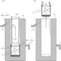
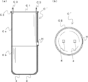
- FIG. 1 It is a schematic diagram of the supercritical fluid extraction system using the supercritical fluid extraction apparatus which concerns on embodiment of this invention. It is a figure which shows the recovery container which concerns on embodiment of this invention, is (a) schematic perspective view, (b) XX'line sectional view. It is a vertical sectional view which shows the recovery container and the separation tank which concerns on embodiment of this invention. It is a figure for demonstrating the manufacturing method of the target object using the supercritical fluid extraction apparatus which concerns on embodiment of this invention. It is a figure for demonstrating the manufacturing method of the target object using the supercritical fluid extraction apparatus which concerns on embodiment of this invention. It is a schematic perspective view which shows the collection container which concerns on other embodiment of this invention.
- FIGS. 1 to 8 a supercritical fluid extraction device according to an embodiment of the present invention and a method for producing a target product using the supercritical fluid extraction device will be described.
- the embodiments shown below are examples of the present invention, and the present invention is not limited to the following embodiments.
- reference numeral 1 indicates a supercritical fluid extraction device according to the present embodiment.
- the supercritical fluid extraction device 1 contains an extraction tank in which the raw material P of the target substance p (see FIGS. 4 and 5) is housed and the supercritical fluid F (see FIG. 4) is supplied.
- A a separation tank B for separating the target object p and the supercritical fluid F, and a recovery container C in which the target object p is housed are provided.
- the supercritical fluid extraction system X includes a pressure regulating valve 2, an evaporator 3, a condensing tank 4, a receiving tank 5, a supercooler 6, and a circulation pump 7. It is composed of a heater 8.
- the pressure regulating valve 2 creates a pressure difference between the extraction tank A and the separation tank B in order to send the mixture M (see FIG. 4) of the raw material P and the supercritical fluid F from the extraction tank A to the separation tank B. adjust.
- the evaporator 3 evaporates and vaporizes the mixture M.
- the condensing tank 4 condenses and liquefies the supercritical fluid F separated inside the separation tank B.
- the receiving tank 5 stores the supercritical fluid F condensed by the condensing tank 4.
- the supercooler 6 supercools the supercritical fluid F stored in the receiving tank 5.
- the circulation pump 7 sends the supercritical fluid F stored in the receiving tank 5 to the extraction tank A via the supercooler 6 and the heater 8.
- the heater 8 heats the supercritical fluid F that has been supercooled by the supercooler 6 to bring it into a supercritical state.
- the above-mentioned components of the supercritical fluid extraction system X cooperate with each other to circulate the supercritical fluid F and separate and extract the target object p using the supercritical fluid F.
- the arrow of the alternate long and short dash line indicates the flow of the mixture M
- the arrow of the broken line indicates the flow of the target object p
- the arrow of the dotted line indicates the flow of the supercritical fluid F.
- the collection container C is formed in a bottomed cylindrical body having an opening C1 above.
- the recovery container C is formed on the peripheral edge of the open end thereof, and has a flange portion C2 protruding toward the inner wall surface B3 (see FIG. 3) of the separation tank B and a pair of handles to which the recovery tool W (see FIG. 5) is attached. It has a part C3 and.
- the material of the collection container C for example, stainless steel is preferably used.
- the pair of handle portions C3 are formed in a substantially inverted U shape, and are provided so as to face the upper side of the inner peripheral surface of the collection container C so that the upper portion thereof protrudes from the opening portion C1.
- the separation tank B is formed in a bottomed cylindrical body having an opening B1 above. Further, the separation tank B has a communication hole B2 for communicating the inside and the outside thereof.
- the communication hole B2 includes a lower communication hole B2a provided below the separation tank B and an upper communication hole B2b provided above the separation tank B.
- connection pipe d1 to which the evaporator 3 is connected is provided at the other end, and the mixture M vaporized and vaporized by the evaporator 3 is the connection pipe d1 and the lower communication hole B2a. And flows into the inside of the separation tank B.
- connection pipe d2 to which the condensation tank 4 is connected is provided at the other end, and the supercritical fluid F separated and extracted inside the separation tank B is the upper communication hole B2b. And, it passes through the connection pipe d2 and flows into the inside of the condensing tank 4.
- the collection container C is configured along the shape of the inner wall surface B3 of the separation tank B, and the bottom surface of the recovery container C is in contact with the inner bottom surface of the separation tank B. It is placed inside. Since the peripheral edge of the flange portion C2 of the recovery container C and the inner wall surface B3 of the separation tank B are arranged so as to form a slight gap, the recovery container C is directed toward the opening B1 of the separation tank B. It is configured to be slidable. That is, the collection container C is detachably arranged inside the separation tank B.
- the collection container C is configured such that the height from the outer bottom surface to the opening end is lower than the height from the inner bottom surface of the separation tank B to the lower communication hole B2a. This prevents the outer peripheral surface of the collection container C from blocking the opening of the lower communication hole B2a.
- the raw material P is an aloe granulated product obtained from aloe vera mesophyll
- the target product p is a waxy aloe extract
- carbon dioxide is used as the supercritical fluid F.
- the target product p is solid or semi-solid
- a raw material other than aloe mesophyll may be used as the raw material P, or a supercritical fluid other than carbon dioxide may be used.
- the worker stores the raw material P in the extraction tank A, and then further supplies the supercritical fluid F to the extraction tank A. More specifically, the operator prepares powdered aloe vera mesophyll by freeze-drying or hot-air drying the aloe vera leaf bark-free mesophyll (transparent gel) portion, and the powdered aloe vera mesophyll is used as the raw material P in the extraction tank A. To be housed in. The worker may produce aloe granulation by sufficiently mixing the prepared powdered aloe vera mesophyll with water, and store the aloe granulation as a raw material P in the extraction tank A.
- the desired component of the raw material P is dissolved in the supercritical fluid F, and a mixture M of the target product p and the supercritical fluid F is produced.
- the detailed illustration in the above step will be omitted.
- the aloe granulated product can be used as the raw material P as it is or after being dried.
- the supercritical fluid F supercritical propane, supercritical ethylene, supercritical 1,1,1,2-tetrafluoroethane and the like can be used, but the safety as food and drink is improved. From the point of view of making it, it is preferable to use carbon dioxide.
- the extraction temperature can be appropriately selected in the temperature range of 28 ° C. to 120 ° C., but the extraction efficiency of plant sterols that can be added to foods such as cyclolanostane compounds and lophenol compounds is improved and relaxed.
- the range of 50 to 69 ° C. is preferable, and the range of 50 to 59 ° C.
- the pressure inside the extraction tank A can be appropriately selected in the range of 5.5 to 60 MPa, but the extraction efficiency of the cyclolanostane compound and the lophenol compound is improved, and the content of the anthraquinone compound is adjusted. In order to reduce the amount, the range of 15 to 60 MPa is preferable, and the range of 15 to 24 MPa is more preferable. Further, from the viewpoint of improving the extraction efficiency of the cyclolanostane compound and the lophenol compound, it is possible to use an entrainer such as ethanol, but from the viewpoint of reducing the content of the anthraquinone compound, the entrainer It is preferable not to use.
- the operator causes the mixture M to flow from the evaporator 3 into the inside of the separation tank B through the connection pipe d1 and the lower communication hole B2a.
- the mixture M is in a substantially gaseous state inside the connecting pipe d1 and the lower communication hole B2a, but the internal pressure of the separation tank B is lower than the internal pressure of the extraction tank A due to the pressure adjusting valve 2. Since it is in the state, the mixture M is separated into the target substance p and the supercritical fluid F when it flows into the inside of the separation tank B. As a result, the target object p is housed in the collection container C.
- the dashed arrow indicates the flow of the mixture M
- the dashed arrow indicates the flow of the target product p
- the dotted arrow indicates the flow of the supercritical fluid F.
- the target product p is accumulated in the collection container C as shown in FIG. 4 (b). Since the target product p is a wax-like aloe extract having a predetermined viscosity, it may adhere to the inner peripheral surface of the collection container C as shown in FIG. 4 (b). Further, the opening B1 of the separation tank B is closed by the lid L while the above-mentioned separation and extraction and storage of the target object p in the collection container are completed.
- the operator removes the lid portion L from the separation tank B, inserts the recovery tool W into the separation tank B, and attaches it to the handle portion C3.
- the recovery tool W is a pair of rod-shaped members whose tips are formed in a hook shape, and an operating device (not shown) for operating the recovery tool W in the vertical direction is connected to the other ends. ing. Therefore, the operator inserts and locks each tip of the recovery tool W into each handle portion C3, and causes the recovery tool W to move upward by the operating device.
- the collection container C is slid toward the opening B1 of the separation tank B and is taken out of the separation tank B.
- the operator uses a tool such as a spatula as appropriate before removing the collection container C from the separation tank B to put the target object p inside. It is collected by peeling it from the wall surface B3 and dropping it inside the collection container C.
- the operator uses a tool such as a spatula to scrape out the target object p accumulated in the collection container C and collect it.
- a tool such as a spatula to scrape out the target object p accumulated in the collection container C and collect it.
- the cyclolanostane compound and the lophenol compound contained in the aloe vera mesophyll are concentrated.
- the guideline for the total amount of the cyclolanostane compound and the lophenol compound in the target product p is preferably 0.5% by mass or more, more preferably 0.6% by mass or more, and particularly preferably 0.7% by mass or more.
- 1% by mass is a guideline.
- the obtained target product p can be used as it is, or as an active ingredient of foods and drinks, cosmetics, pharmaceuticals and the like through further operations such as extraction and drying.
- a drug containing the object p of the present invention can be appropriately produced by combining the object p of the present invention with a pharmaceutically acceptable formulation carrier or the like, and is usually used as a formulation carrier in formulation.
- Additives such as excipients, binders, disintegrants, lubricants, stabilizers, flavoring agents, diluents, surfactants, and injection solvents can be used.
- the object of each of the manufacturing method (a) using the recovery container C, the manufacturing method (b) without the recovery container C, and the manufacturing method (c) using a bucket instead of the recovery container C of the present invention is shown below.
- the cyclolanostane compound and lophenol compound recovery efficiency is the ratio of the amount of the cyclolanostane compound and the lophenol compound in the recovered target product p to the amount of the cyclolanostane compound and the lophenol compound in the raw material P. Is expressed as a 100-minute rate.
- the bucket has a bottomed cylindrical shape, the outer diameter gradually decreases toward the bottom, and an inverted U-shaped handle is provided at the top, which is usually commercially available. ..
- the operator can remove the collection container C from the separation tank B and easily and surely collect the target object p from the inside of the collection container C.
- the difficulty of the recovery work due to the structure such as the height of the separation tank B is eliminated, and high recovery efficiency can be realized.
- the collection container C is a bottomed cylindrical body having an opening C1 above, the target object separated and extracted inside the separation tank B can be easily and efficiently inside the collection container C by using gravity. Can be accommodated in.
- the separation tank B is a bottomed cylindrical body having an opening B1 above, and the collection container C is configured to be slidable toward the opening B1 of the separation tank B, so that the separation tank B can be formed.
- the structure is simple, the collection container C can be easily taken out through the opening B1 above the separation tank B.
- the recovery container C since the outer shape of the recovery container C is configured along the shape of the inner wall surface of the separation tank B, the recovery container C can be stably placed inside the separation tank B while ensuring a large volume of the recovery container C. It becomes possible to arrange.
- the recovery container C has the flange portion C2
- the gap between the upper part of the recovery container C and the inner wall surface B3 of the separation tank B is made as small as possible, and the purpose is to be between the recovery container C and the separation tank B through this gap. It is possible to suppress the situation where the object p gets in.
- the collection container C has the handle portion C3 to which the collection tool W is attached, it is possible to easily and quickly take out the collection container C from the separation tank B.
- the supercritical fluid F is carbon dioxide, it is possible to safely and efficiently perform the separation and extraction work.
- the height of the collection container C is set so that the outer peripheral surface of the collection container C does not block the opening of the lower communication hole B2a, but the height of the collection container C is the above. It may be further increased from the embodiment of. In this case, the preferred configurations of the recovery container C'and the separation tank B'will be described with reference to FIGS. 6 to 8 as another embodiment.
- the collection container C' is composed of a first collection container component Ca and a second collection container component Cb which are connected in a vertically divisible manner.
- the first recovery container structure Ca and the second recovery container structure Cb are connected by a plurality of connecting means S provided on the outer peripheral surface thereof. It constitutes one bottomed cylindrical body.
- the length of protrusion of the first recovery container structure Ca from the outer peripheral surface of the plurality of connecting means S is shorter than the length of protrusion of the first recovery container structure Ca of the flange portion C2 from the outer peripheral surface.
- the plurality of connecting means S in the present embodiment are so-called snap locks, but the present invention is not limited to this, and the first recovery container component Ca and the second recovery container structure Cb can be freely divided and connected. Any means may be used as long as it is a thing.
- the first recovery container structure Ca and the second recovery container structure Cb can be easily divided by canceling the engaged state of the plurality of connecting means S. can.
- the first recovery container structure Ca has a flange portion C2 protruding toward the inner wall surface B3 of the separation tank B, and a pair of handle portions C3 to which the recovery tool W is attached. Further, the first recovery container structure Ca has a through hole H on the outer peripheral surface thereof.
- the second collection container structure Cb has two fitting holes g on the outer bottom surface thereof. Further, the protruding length of the first recovery container structure Ca in the through hole H from the outer peripheral surface is substantially the same as the protruding length of the first recovery container structure Ca in the flange portion C2 from the outer peripheral surface. ..
- FIG. 8 is a vertical cross-sectional view of the collection container C'configured as described above when it is arranged inside the separation tank B'. Note that FIG. 8B is an enlarged view of the dotted frame portion in FIG. 8A.
- the separation tank B' has two fitting protrusions j to be fitted into each fitting hole g on the inner bottom surface thereof. That is, the positioning means is composed of the fitting hole g and the fitting protrusion j, and the positioning means restrains the rotational operation of the collection container C'inside the separation tank B'. Since the separation tank B'has the same structure as the separation tank B except for the structure having the fitting protrusion j, the description thereof will be omitted. Further, the configuration of the positioning means does not necessarily have to be the fitting hole g and the fitting protrusion j, and is not particularly limited as long as the rotation operation of the collection container C'is restricted.
- the height from the outer bottom surface of the collection container C'to the through hole H is configured to be substantially the same as the height from the inner bottom surface of the separation tank B'to the lower communication hole B2a.
- the volume of the recovery container C' can be arbitrarily increased without limiting the height of the recovery container C', and the target object p is placed on the inner peripheral surface of the separation tank B'. By adhering, it is possible to suppress a situation in which the collection work becomes troublesome.
- fitting hole g and the fitting protrusion j prevent a situation in which the outer peripheral surface of the recovery container C'blocks the opening of the lower communication hole B2a due to an unexpected rotation of the recovery container C'.
- the recovery container C' is composed of the first recovery container structure Ca and the second recovery container structure Cb that can be divided, the target object accumulated at the bottom of the second recovery container structure Cb. p can be easily recovered.
- the target product p is a wax-like aloe extract
- the target product p is a liquid or other solid.
- it can be applied even when it is in the form or semi-solid.
Landscapes
- Health & Medical Sciences (AREA)
- Natural Medicines & Medicinal Plants (AREA)
- Chemical & Material Sciences (AREA)
- Chemical Kinetics & Catalysis (AREA)
- Life Sciences & Earth Sciences (AREA)
- Microbiology (AREA)
- Pharmacology & Pharmacy (AREA)
- Botany (AREA)
- Medical Informatics (AREA)
- Medicinal Chemistry (AREA)
- Alternative & Traditional Medicine (AREA)
- Mycology (AREA)
- Biotechnology (AREA)
- Epidemiology (AREA)
- Animal Behavior & Ethology (AREA)
- General Health & Medical Sciences (AREA)
- Public Health (AREA)
- Veterinary Medicine (AREA)
- Engineering & Computer Science (AREA)
- Extraction Or Liquid Replacement (AREA)
Priority Applications (2)
| Application Number | Priority Date | Filing Date | Title |
|---|---|---|---|
| JP2022510416A JPWO2021193418A1 (https=) | 2020-03-24 | 2021-03-19 | |
| EP21776954.6A EP4129434A4 (en) | 2020-03-24 | 2021-03-19 | APPARATUS FOR SUPERCRITICAL FLUID EXTRACTION AND METHOD FOR PRODUCING A TARGET PRODUCT THEREOF |
Applications Claiming Priority (2)
| Application Number | Priority Date | Filing Date | Title |
|---|---|---|---|
| JP2020-053253 | 2020-03-24 | ||
| JP2020053253 | 2020-03-24 |
Publications (1)
| Publication Number | Publication Date |
|---|---|
| WO2021193418A1 true WO2021193418A1 (ja) | 2021-09-30 |
Family
ID=77891739
Family Applications (1)
| Application Number | Title | Priority Date | Filing Date |
|---|---|---|---|
| PCT/JP2021/011339 Ceased WO2021193418A1 (ja) | 2020-03-24 | 2021-03-19 | 超臨界流体抽出装置及びそれを用いた目的物の製造方法 |
Country Status (3)
| Country | Link |
|---|---|
| EP (1) | EP4129434A4 (https=) |
| JP (1) | JPWO2021193418A1 (https=) |
| WO (1) | WO2021193418A1 (https=) |
Citations (6)
| Publication number | Priority date | Publication date | Assignee | Title |
|---|---|---|---|---|
| JPS61291004A (ja) * | 1985-06-19 | 1986-12-20 | Hitachi Ltd | 超臨界ガス抽出装置 |
| JPS6265703A (ja) * | 1985-07-09 | 1987-03-25 | ソシエテ・ナシオナル・エルフ・アキテ−ヌ | 流体から溶解性物質を分離する装置 |
| JPH07506535A (ja) * | 1993-03-05 | 1995-07-20 | イスコ・インコーポレーテッド | 超臨界流体抽出装置及び方法 |
| JP2007120972A (ja) | 2005-10-25 | 2007-05-17 | Jasco Corp | 超臨界システム |
| WO2007060911A1 (ja) * | 2005-11-25 | 2007-05-31 | Morinaga Milk Industry Co., Ltd. | アロエベラ抽出物、アロエベラ抽出物の製造方法、高血糖改善剤 |
| US20190282923A1 (en) * | 2018-03-15 | 2019-09-19 | Waters Technologies Corporation | Discrete extract collection system for co2-based fluid extraction |
Family Cites Families (2)
| Publication number | Priority date | Publication date | Assignee | Title |
|---|---|---|---|---|
| JPH08141306A (ja) * | 1994-11-24 | 1996-06-04 | Japan Tobacco Inc | 半径方向流れ流体抽出方法及び装置 |
| US6413428B1 (en) * | 1999-09-16 | 2002-07-02 | Berger Instruments, Inc. | Apparatus and method for preparative supercritical fluid chromatography |
-
2021
- 2021-03-19 JP JP2022510416A patent/JPWO2021193418A1/ja active Pending
- 2021-03-19 EP EP21776954.6A patent/EP4129434A4/en not_active Withdrawn
- 2021-03-19 WO PCT/JP2021/011339 patent/WO2021193418A1/ja not_active Ceased
Patent Citations (6)
| Publication number | Priority date | Publication date | Assignee | Title |
|---|---|---|---|---|
| JPS61291004A (ja) * | 1985-06-19 | 1986-12-20 | Hitachi Ltd | 超臨界ガス抽出装置 |
| JPS6265703A (ja) * | 1985-07-09 | 1987-03-25 | ソシエテ・ナシオナル・エルフ・アキテ−ヌ | 流体から溶解性物質を分離する装置 |
| JPH07506535A (ja) * | 1993-03-05 | 1995-07-20 | イスコ・インコーポレーテッド | 超臨界流体抽出装置及び方法 |
| JP2007120972A (ja) | 2005-10-25 | 2007-05-17 | Jasco Corp | 超臨界システム |
| WO2007060911A1 (ja) * | 2005-11-25 | 2007-05-31 | Morinaga Milk Industry Co., Ltd. | アロエベラ抽出物、アロエベラ抽出物の製造方法、高血糖改善剤 |
| US20190282923A1 (en) * | 2018-03-15 | 2019-09-19 | Waters Technologies Corporation | Discrete extract collection system for co2-based fluid extraction |
Non-Patent Citations (1)
| Title |
|---|
| See also references of EP4129434A4 |
Also Published As
| Publication number | Publication date |
|---|---|
| JPWO2021193418A1 (https=) | 2021-09-30 |
| EP4129434A1 (en) | 2023-02-08 |
| EP4129434A4 (en) | 2024-04-24 |
Similar Documents
| Publication | Publication Date | Title |
|---|---|---|
| EP3475402B1 (en) | Method of extraction of cannabinoids using liquid carbon dioxide | |
| US10646793B2 (en) | Elevated multi-stage chilled filter system | |
| BR112019026417A2 (pt) | processo para extrair canabinóides | |
| EP3461546B1 (en) | Cannabinoid extraction process | |
| US20200038777A1 (en) | Methods to Reduce Chlorophyll Co-Extraction Through Extraction of Select Essential Oils and Aromatic Isolates | |
| JP2005514193A (ja) | 油抽出方法およびそのための装置 | |
| US10092855B2 (en) | CO2 extraction and filtration system | |
| JPS61501968A (ja) | 液体co↓2/共溶媒抽出 | |
| US20150122272A1 (en) | Methods for creating concentrated plant material solutions | |
| KR20110019974A (ko) | 초임계 이산화탄소를 이용한 커피 원두의 추출방법 | |
| JP2003508207A (ja) | 溶剤残渣の除去装置及び方法 | |
| WO2021193418A1 (ja) | 超臨界流体抽出装置及びそれを用いた目的物の製造方法 | |
| JPH066028B2 (ja) | 香味成分の抽出方法 | |
| CN105194903A (zh) | 一种草本浓缩液生产工艺 | |
| US20170157529A1 (en) | Oil separation system | |
| JP4666923B2 (ja) | ホソバヤマジソ精油の製造方法、及びチモールの製造方法 | |
| CN105289040B (zh) | 一种天然植物粉生产工艺 | |
| JP2003508203A (ja) | 混合液の分離装置及び分離方法 | |
| KR20020042825A (ko) | 용매 잔류물 제거 장치 및 방법 | |
| KR101637339B1 (ko) | 농축폐액 파라핀 고화체에서의 파라핀 회수 방법 및 그 장치 | |
| WO2023199165A1 (en) | Extractive process for obtaining an oil based on phytocannabinoids | |
| CA3063941A1 (en) | Closed loop chilled solvent feed for cannabinoid extraction | |
| CN110643433A (zh) | 一种石斛花精油的提取方法 | |
| JPH05310602A (ja) | 超臨界流体を用いた植物体から水溶性成分の抽出方法 | |
| JP2003508204A (ja) | 残留溶剤濃度を低減させる装置および方法 |
Legal Events
| Date | Code | Title | Description |
|---|---|---|---|
| 121 | Ep: the epo has been informed by wipo that ep was designated in this application |
Ref document number: 21776954 Country of ref document: EP Kind code of ref document: A1 |
|
| ENP | Entry into the national phase |
Ref document number: 2022510416 Country of ref document: JP Kind code of ref document: A |
|
| NENP | Non-entry into the national phase |
Ref country code: DE |
|
| ENP | Entry into the national phase |
Ref document number: 2021776954 Country of ref document: EP Effective date: 20221024 |