WO2021193107A1 - シリンダ装置とピストンロッドの製造方法 - Google Patents
シリンダ装置とピストンロッドの製造方法 Download PDFInfo
- Publication number
- WO2021193107A1 WO2021193107A1 PCT/JP2021/009810 JP2021009810W WO2021193107A1 WO 2021193107 A1 WO2021193107 A1 WO 2021193107A1 JP 2021009810 W JP2021009810 W JP 2021009810W WO 2021193107 A1 WO2021193107 A1 WO 2021193107A1
- Authority
- WO
- WIPO (PCT)
- Prior art keywords
- polishing
- piston rod
- cylinder
- less
- film
- Prior art date
- Legal status (The legal status is an assumption and is not a legal conclusion. Google has not performed a legal analysis and makes no representation as to the accuracy of the status listed.)
- Ceased
Links
Images











Classifications
-
- B—PERFORMING OPERATIONS; TRANSPORTING
- B24—GRINDING; POLISHING
- B24B—MACHINES, DEVICES, OR PROCESSES FOR GRINDING OR POLISHING; DRESSING OR CONDITIONING OF ABRADING SURFACES; FEEDING OF GRINDING, POLISHING, OR LAPPING AGENTS
- B24B5/00—Machines or devices designed for grinding surfaces of revolution on work, including those which also grind adjacent plane surfaces; Accessories therefor
- B24B5/18—Machines or devices designed for grinding surfaces of revolution on work, including those which also grind adjacent plane surfaces; Accessories therefor involving centreless means for supporting, guiding, floating or rotating work
- B24B5/22—Machines or devices designed for grinding surfaces of revolution on work, including those which also grind adjacent plane surfaces; Accessories therefor involving centreless means for supporting, guiding, floating or rotating work for grinding cylindrical surfaces, e.g. on bolts
-
- B—PERFORMING OPERATIONS; TRANSPORTING
- B24—GRINDING; POLISHING
- B24B—MACHINES, DEVICES, OR PROCESSES FOR GRINDING OR POLISHING; DRESSING OR CONDITIONING OF ABRADING SURFACES; FEEDING OF GRINDING, POLISHING, OR LAPPING AGENTS
- B24B21/00—Machines or devices using grinding or polishing belts; Accessories therefor
- B24B21/02—Machines or devices using grinding or polishing belts; Accessories therefor for grinding rotationally symmetrical surfaces
-
- B—PERFORMING OPERATIONS; TRANSPORTING
- B24—GRINDING; POLISHING
- B24B—MACHINES, DEVICES, OR PROCESSES FOR GRINDING OR POLISHING; DRESSING OR CONDITIONING OF ABRADING SURFACES; FEEDING OF GRINDING, POLISHING, OR LAPPING AGENTS
- B24B21/00—Machines or devices using grinding or polishing belts; Accessories therefor
- B24B21/006—Machines or devices using grinding or polishing belts; Accessories therefor for special purposes, e.g. for television tubes, car bumpers
-
- B—PERFORMING OPERATIONS; TRANSPORTING
- B24—GRINDING; POLISHING
- B24B—MACHINES, DEVICES, OR PROCESSES FOR GRINDING OR POLISHING; DRESSING OR CONDITIONING OF ABRADING SURFACES; FEEDING OF GRINDING, POLISHING, OR LAPPING AGENTS
- B24B21/00—Machines or devices using grinding or polishing belts; Accessories therefor
- B24B21/04—Machines or devices using grinding or polishing belts; Accessories therefor for grinding plane surfaces
- B24B21/12—Machines or devices using grinding or polishing belts; Accessories therefor for grinding plane surfaces involving a contact wheel or roller pressing the belt against the work
-
- B—PERFORMING OPERATIONS; TRANSPORTING
- B24—GRINDING; POLISHING
- B24B—MACHINES, DEVICES, OR PROCESSES FOR GRINDING OR POLISHING; DRESSING OR CONDITIONING OF ABRADING SURFACES; FEEDING OF GRINDING, POLISHING, OR LAPPING AGENTS
- B24B5/00—Machines or devices designed for grinding surfaces of revolution on work, including those which also grind adjacent plane surfaces; Accessories therefor
- B24B5/18—Machines or devices designed for grinding surfaces of revolution on work, including those which also grind adjacent plane surfaces; Accessories therefor involving centreless means for supporting, guiding, floating or rotating work
- B24B5/307—Means for supporting work
-
- F—MECHANICAL ENGINEERING; LIGHTING; HEATING; WEAPONS; BLASTING
- F16—ENGINEERING ELEMENTS AND UNITS; GENERAL MEASURES FOR PRODUCING AND MAINTAINING EFFECTIVE FUNCTIONING OF MACHINES OR INSTALLATIONS; THERMAL INSULATION IN GENERAL
- F16F—SPRINGS; SHOCK-ABSORBERS; MEANS FOR DAMPING VIBRATION
- F16F9/00—Springs, vibration-dampers, shock-absorbers, or similarly-constructed movement-dampers using a fluid or the equivalent as damping medium
- F16F9/32—Details
-
- F—MECHANICAL ENGINEERING; LIGHTING; HEATING; WEAPONS; BLASTING
- F16—ENGINEERING ELEMENTS AND UNITS; GENERAL MEASURES FOR PRODUCING AND MAINTAINING EFFECTIVE FUNCTIONING OF MACHINES OR INSTALLATIONS; THERMAL INSULATION IN GENERAL
- F16F—SPRINGS; SHOCK-ABSORBERS; MEANS FOR DAMPING VIBRATION
- F16F9/00—Springs, vibration-dampers, shock-absorbers, or similarly-constructed movement-dampers using a fluid or the equivalent as damping medium
- F16F9/32—Details
- F16F9/3207—Constructional features
- F16F9/3221—Constructional features of piston rods
-
- F—MECHANICAL ENGINEERING; LIGHTING; HEATING; WEAPONS; BLASTING
- F16—ENGINEERING ELEMENTS AND UNITS; GENERAL MEASURES FOR PRODUCING AND MAINTAINING EFFECTIVE FUNCTIONING OF MACHINES OR INSTALLATIONS; THERMAL INSULATION IN GENERAL
- F16F—SPRINGS; SHOCK-ABSORBERS; MEANS FOR DAMPING VIBRATION
- F16F2226/00—Manufacturing; Treatments
- F16F2226/02—Surface treatments
Definitions
- the present invention relates to a cylinder device and a method for manufacturing a piston rod.
- the present application claims priority based on Japanese Patent Application No. 2020-057547 filed in Japan on March 27, 2020, the contents of which are incorporated herein by reference.
- Patent Document 1 the groove portion of the contact surface with the element in the pulley for a belt-type continuously variable transmission is polished with a wrap film, and the protruding peak height Rpk is 0.09 ⁇ m or less with respect to the surface roughness.
- a technique for processing a protruding valley depth Rvk to 0.4 to 1.3 ⁇ m is disclosed.
- the level difference of the core portion on the sliding surface of the piston rod is small, the familiarity from the dry state to the steady state is affected.
- the level difference of the core portion is considered to affect the riding comfort of the automobile. That is, if the surface texture of the sliding surface of the piston rod is inappropriate, the riding comfort of the automobile may be deteriorated. Further, if the surface texture of the sliding surface of the piston rod is inappropriate, the sliding characteristics may change with time.
- the problem to be solved by the present invention is to improve the wear resistance of the sliding surface of the piston rod to reduce the change in the sliding characteristics of the piston rod with time and to make it easy to adapt from the dry state to the steady state. It is an object of the present invention to provide a method for manufacturing a cylinder device and a piston rod, which can improve the above.
- the present invention has adopted the following aspects.
- the sliding surface of the piston rod has a chrome plated layer; on the sliding surface, the overhang valley, which is a characteristic evaluation parameter of the plateau structure surface described in JIS B 0671-2 and ISO 13565-2.
- the part depth Rvk is 0.06 ⁇ m or more and less than the plating thickness
- the protruding peak height Rpk is 0 ⁇ m or more and 0.04 ⁇ m or less
- the level difference Rk of the core part is 0.08 ⁇ m or more and 0. .Cylinder device of 16 ⁇ m or less.
- a method for manufacturing a piston rod having a chrome plating layer formed on a sliding surface which includes a polishing treatment step performed after the formation of the chrome plating layer, and the polishing treatment step uses a first polishing film.
- the protrusion valley depth Rvk which is a characteristic evaluation parameter of the plateau structure surface described in JIS B 0671-2 and ISO 13565-2, is 0.06 ⁇ m or more and the plating thickness of the chrome plating is obtained by polishing.
- the method for manufacturing a piston rod according to (2) above may be as follows: In the initial polishing process, a polishing material having a coarse particle size of # 600 or less is used as the first polishing film. The initial polished surface is formed; in the finish polishing process, the plateau surface is formed by using a polishing material having a fine particle size of # 800 or more as the second polishing film.
- the sliding surface of the piston rod has a suitable depth of the protruding valley portion, a height of the protruding peak portion, and a level difference of the core portion. Therefore, it has excellent wear resistance, has low aggression against the oil seal, can reduce the wear of the oil seal, and can reduce the change in sliding characteristics with time. Further, it is possible to provide a suspension device which has good familiarity from a dry state to a steady state and does not deteriorate the riding comfort of an automobile when applied to a piston rod for an automobile suspension device.
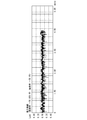
- FIG. 1 It is a graph which shows an example of the surface roughness curve of the sliding surface in the piston rod obtained by the manufacturing method of the piston rod which concerns on one Embodiment of this invention. It is a figure which shows the whole structure of the shock absorber which is the cylinder device provided with the piston rod, and is the sectional view seen in the cross section including the central axis CL.
- the sliding surface of the piston rod has the characteristics of the surface roughness curve shown in FIG.
- FIG. 1 It is a front view which shows the outer shape of the piston rod and the position of a sliding surface.
- FIG. 1 It is a figure which shows the superstructure of the shock absorber, and is the enlarged sectional view of the part A of FIG.
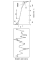
- FIG. 1 is a graph showing an example of a surface roughness curve of a sliding surface of a piston rod whose surface has been polished according to a manufacturing method described later.
- FIG. 2 is a view showing the entire structure of a shock absorber, which is a cylinder device provided with the piston rod, and is a cross-sectional view seen in a cross section including the central axis CL.
- the sliding surface of this piston rod has the characteristics of the surface roughness curve shown in FIG. Before explaining the surface roughness of the sliding surface of the piston rod, first, the overall configuration of the cylinder device including the piston rod will be described.
- the cylinder device 1 shown in FIG. 2 is a shock absorber used for a suspension device of a vehicle such as an automobile or a railroad vehicle, and specifically, is used for a strut type suspension device of an automobile.
- the cylinder device 1 is provided between a cylindrical inner cylinder (cylinder) 2 in which a working liquid is sealed and an inner cylinder 2 having a diameter larger than that of the inner cylinder 2 and provided on the outer peripheral side of the inner cylinder 2. It also has a bottomed cylindrical outer cylinder 3 that forms a reservoir chamber R in which the working gas is sealed. That is, the cylinder device 1 is a double-cylinder type shock absorber in which the inner cylinder 2 is provided in the outer cylinder 3.
- the outer cylinder 3 includes a cylindrical side wall portion 7 and a bottom portion 8 that closes one end side of the side wall portion 7 in the axial direction.
- the inner cylinder 2 has a cylindrical shape.
- the inner cylinder 2 is engaged with the bottom portion 8 of the outer cylinder 3 via an annular base valve 13 attached to one end in the axial direction thereof.
- the inner cylinder 2 has an opening 9 on the side opposite to the bottom 8 of the side wall portion 7 of the outer cylinder 3 via an annular metal rod guide 11 attached to the other end portion in the axial direction thereof. Is engaged in.
- the base valve 13 is positioned in the radial direction by being placed on the bottom 8 of the outer cylinder 3 in a state of being fitted and fixed to the inner cylinder 2. As a result, the base valve 13 is arranged coaxially with the outer cylinder 3.
- the rod guide 11 is fitted to the inner cylinder 2 and the side wall portion 7 of the outer cylinder 3, so that the other end portion of the inner cylinder 2 in the axial direction is arranged coaxially with the outer cylinder 3.
- an annular oil seal (seal member) 15 is arranged on the side opposite to the bottom 8 side.
- the oil seal 15 is also fitted to the inner peripheral portion of the side wall portion 7 on the opening 9 side.
- a locking portion 16 is formed on the side of the outer cylinder 3 opposite to the bottom portion 8 by being bent inward in the radial direction.
- the oil seal 15 is supported on one end side of the cylinder by being locked by the locking portion 16 on the outer side in the axial direction.
- a piston 25 is slidably fitted in the inner cylinder 2.
- the piston 25 defines the inside of the inner cylinder 2 into a first chamber 22 and a second chamber 23.
- the first chamber 22 is provided between the piston 25 in the inner cylinder 2 and the rod guide 11.
- the second chamber 23 is provided between the piston 25 in the inner cylinder 2 and the base valve 13.
- the second chamber 23 in the inner cylinder 2 is defined as the reservoir chamber R by the base valve 13 provided on one end side of the inner cylinder 2.
- a metal piston rod 21 is connected to the piston 25 by a nut 26.
- the piston rod 21 has a columnar large diameter portion 21a having a constant outer diameter, passes through the rod guide 11 and the oil seal 15, and goes from the inner cylinder 2 and the outer cylinder 3, that is, one end side of the cylinder to the outside. It is extended.
- the piston rod 21 is slidably inserted into the inside of each of the rod guide 11 and the oil seal 15 in the large diameter portion 21a.
- One end of the piston rod 21 is arranged inside the outer cylinder 3 and the inner cylinder 2, and the other end is arranged outside the outer cylinder 3 and the inner cylinder 2.
- a small diameter portion 21b is formed on one end side of the large diameter portion 21a of the piston rod 21.
- the piston 25 is inserted into the small diameter portion 21b, and the nut 26 is screwed into the screw portion formed on the tip end side of the small diameter portion 21b, whereby the piston 25 is attached to the piston rod 21.
- An annular groove 21c is formed in the large diameter portion 21a of the piston rod 21 at a position close to the base end portion of the small diameter portion 21b.
- a ring-shaped internal stopper 24 is mounted so as to be engaged with the annular groove 21c.
- a ring-shaped rebound rubber 19 is arranged on the upper side of the internal stopper 24.
- the position P1 slightly separated from the annular groove 21c from the piston mounting side toward the opposite side, and the bolt portion 21d serving as the mounting portion to the vehicle body.
- the sliding range A with respect to the rod guide 11 and the oil seal 15 is set between the connecting portion P2 and the rod guide 11.
- a chrome plating layer is formed on the outer surface of the piston rod 21.
- the surface of the sliding range A of the large diameter portion 21a (the sliding surface of the chrome plating layer; hereinafter, may be simply referred to as “sliding surface A”) is a polished surface. ..
- This polished surface has a protruding peak height Rpk of 0 ⁇ m or more and 0.04 ⁇ m or less, which is a characteristic evaluation parameter of the plateau structure surface described in JIS B 0671-2 and ISO 13565-2, and is of the core part.
- the level difference Rk is 0.08 ⁇ m or more and 0.16 ⁇ m or less, and the protrusion valley depth Rvk is 0.06 ⁇ m or more and less than the plating thickness. Details of this polished surface will be described later.
- the piston rod 21 moves in the axial direction integrally with the piston 25.
- the oil seal 15 through which the large diameter portion 21a of the piston rod 21 is inserted closes between the outer cylinder 3 and the piston rod 21, and the working liquid in the inner cylinder 2 and the working gas and working liquid in the reservoir chamber R. Prevents and from leaking to the outside.
- the piston 25 is formed with a passage 27 and a passage 28 penetrating in the axial direction.
- the passages 27 and 28 allow communication between the first chamber 22 and the second chamber 23.
- the piston 25 is provided with an annular disc valve 28a capable of closing the passage 28 by contacting the piston 25 on the side opposite to the bottom portion 8 in the axial direction.
- the piston 25 is provided with an annular disc valve 27a that can close the passage 27 by contacting the piston 25 on the bottom 8 side in the axial direction.
- the piston 25 moves in the direction of narrowing the second chamber 23.
- the passage 28 is opened, and a damping force is generated at that time.
- the disc valve 27a moves in the direction in which the piston 25 narrows the first chamber 22.
- the base valve 13 shown in FIG. 2 is formed with a passage 28 and a passage 29 penetrating in the axial direction.
- the passages 28 and 29 allow communication between the second chamber 23 and the reservoir chamber R.
- the base valve 13 is provided with an annular disc valve 30 capable of closing the passage 28 by abutting on the base valve 13 on the bottom 8 side in the axial direction thereof. Further, on the side of the base valve 13 opposite to the bottom portion 8 in the axial direction, an annular disc valve 31 that can close the passage 29 by contacting the base valve 13 is arranged.
- the disc valve 30 allows the flow of the working liquid from the second chamber 23 through the passage 28 to the reservoir chamber R side, while restricting the flow of the working liquid through the passage 28 in the opposite direction, check. It is a valve.
- the disc valve 30 is a damping valve that opens the passage 28 when the piston rod 21 moves to the contraction side and the pressure in the second chamber 23 becomes higher than the pressure in the reservoir chamber R by a predetermined value or more, and generates a damping force at that time. It has become.
- the disc valve 31 allows the flow of the working liquid from the reservoir chamber R toward the second chamber 23 side through the passage 29, and regulates the flow of the working liquid through the passage 29 in the opposite direction, check. It is a valve.
- the disc valve 31 is a suction valve that allows the working liquid to flow from the reservoir chamber R into the second chamber 23 without substantially generating a damping force at that time.
- a cylindrical mounting eye 33 is fixed to the outside of the bottom 8 of the outer cylinder 3.
- a portion of the piston rod 21 outside the oil seal 15 and a mounting eye 33 are mounted between the relative moving portions to be mounted.
- the cylinder device 1 is integrated with the piston rod 21 due to the relative movement that occurs in the mounting target portion, and the piston 25 slides in the inner cylinder 2 in the axial direction to change the volumes of the first chamber 22 and the second chamber 23. ..
- a damping force is generated by the flow resistance of the oil liquid generated in the piston 25 and the base valve 13.
- the piston rod 21 is connected to the vehicle body side and the mounting eye 33 is connected to the wheel side of the vehicle to generate a damping force with respect to the relative movement of the wheels with respect to the vehicle body.
- the rod guide 11 has a substantially stepped ring shape.
- the rod guide 11 has a large-diameter portion 11a having a cylindrical outer peripheral surface formed on one side in the axial direction, and a small-diameter portion having a cylindrical outer peripheral surface having a smaller diameter than the outer peripheral surface of the large-diameter portion 11a on the other side in the axial direction. 11b is formed.
- the large diameter portion 11a and the small diameter portion 11b are formed coaxially.
- the rod guide 11 is fitted to the inner peripheral surface of the outer cylinder 3 in the large diameter portion 11a, and is fitted to the inner peripheral surface of the inner cylinder 2 in the small diameter portion 11b.
- annular convex portion 11c protruding in the axial direction is formed at the end of the rod guide 11 on the large diameter portion 11a side in the axial direction.
- the annular convex portion 11c is formed with a communication hole 11d that penetrates the rod guide 11 along the axial direction at its radial inner position.
- the communication hole 11d is open to the reservoir chamber R between the outer cylinder 3 and the inner cylinder 2 on the side opposite to the annular convex portion 11c in the axial direction of the rod guide 11.
- the oil seal 15 has an integrally molded seal member main body 37 in which a metal annular member 36 is embedded in a synthetic rubber sealing material 35, and a metal annular spring 38.
- the annular member 36 is for maintaining the shape of the sealing material 35, and gives the sealing member main body 37 strength for fixing to the target portion.
- the seal member main body 37 is supported on one end side of the cylinder by sandwiching the position of the annular member 36 in the radial direction between the annular convex portion 11c of the rod guide 11 and the locking portion 16 of the outer cylinder 3.
- the sealing material 35 has a dust strip portion 35a, an oil lip portion 35b, a sealing ring portion 35c, and a check lip portion 35d.
- the dust strip portion 35a extends in a cylindrical shape from the inner peripheral surface side of the annular member 36 to one side in the axial direction.
- the oil lip portion 35b extends from the inner peripheral surface side of the annular member 36 to the other side in the axial direction in a cylindrical shape.
- the seal member main body 37 has a large diameter portion 21a of the piston rod 21 inserted into the oil lip portion 35b and the dust strip portion 35a so as to be slidable.
- the dust strip portion 35a and the oil lip portion 35b seal a gap between themselves and the large diameter portion 21a of the piston rod 21.
- the seal ring portion 35c protrudes in an annular shape from the outer peripheral surface side of the annular member 36 to the same side as the oil lip portion 35b in the axial direction.
- the seal ring portion 35c comes into contact with the annular convex portion 11c of the rod guide 11 and the outer cylinder 3 at the same time to seal the gap between the outer cylinder 3 and the rod guide 11.
- the check lip portion 35d protrudes from an intermediate position in the radial direction of the annular member 36 in an annular tubular shape on the same side as the oil lip portion 35b in the axial direction.
- the check lip portion 35d is in contact with the annular convex portion 11c of the rod guide 11 in the radial direction.
- the check lip portion 35d allows the working fluid leaking from the gap between the rod guide 11 and the large diameter portion 21a of the piston rod 21 to flow to the reservoir chamber R through the communication hole 11d, while allowing the working fluid to flow in the opposite direction.
- the spring 38 is attached to the outer peripheral portion of the oil lip portion 35b. The spring 38 presses the oil lip portion 35b on the outer circumference of the large diameter portion 21a of the piston rod 21 to seal the gap.
- the piston rod 21 or the outer cylinder 3 repeatedly receives an impact from the outside. Each time an impact force is received, the piston rod 21 moves to the contraction side or the extension side, and a damping force acts at that time. In this way, the cylinder device 1 functions as a shock absorber used in the strut suspension of an automobile. Further, since the chrome plating layer is provided on the outer peripheral surface of the large diameter portion 21a of the piston rod 21 to form a sliding surface, even if the large diameter portion 21a repeatedly slides on the seal member, the chrome plating layer is formed. Exhibits excellent sliding characteristics and can exhibit excellent wear resistance.
- the sliding surface A has a protruding peak height Rpk of 0 ⁇ m or more, which is a characteristic evaluation parameter of the plateau structure surface described in JIS B 0671-2 and ISO 13565-2.
- the level difference Rk of the core portion is 0.08 ⁇ m or more and 0.16 ⁇ m or less
- the protrusion valley depth Rvk is 0.06 ⁇ m or more and less than the plating thickness.
- FIG. 1 shows an example of the roughness curve of the sliding surface A of the piston rod 21 polished so as to have the protruding valley depth Rvk, the protruding peak height Rpk, and the core level difference Rk in these ranges. There is.
- the piston rod 21 can be smoothly slid.
- the sliding surface A of the piston rod 21 becomes familiar from the dry state to the steady state. Therefore, when the piston rod 21 is used in an automobile suspension device, it is possible to provide a suspension device (cylinder device) 1 that does not reduce the riding comfort of the automobile.
- the sliding surface A has a suitable protruding valley depth, protruding peak height, and core level difference. Therefore, the piston rod 21 has excellent wear resistance, has low aggression against the oil seal 15, can reduce the wear of the oil seal 15, and can reduce the change in sliding characteristics with time.
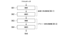
- FIG. 6 is a flow chart showing an outline of a method for manufacturing the piston rod 21.
- a rod material such as a steel rod made of a steel material of a type suitable for the piston rod is prepared.
- This rod material is subjected to heat treatment such as high frequency quenching and tempering in the heat treatment step S2, and is subjected to surface hardening treatment necessary for a piston rod.
- the cutting step S3 and the grinding step S4 are performed so as to have the outer shape of the piston rod 21 shown in FIG.
- the outer shape of the piston rod 21 including the small diameter portion 21b, the annular groove 21c, the bolt portion 21d, and the like is obtained.
- the piston rod is subjected to a chrome plating treatment to form a chrome plating layer having a film thickness of about 20 ⁇ m, which is used as a rod material.
- the rod material is subjected to the outer diameter polishing described below to obtain the target piston rod 21.
- FIG. 7 shows the details of the polishing process step S6.
- the polishing treatment step S6 includes a first polishing treatment step S61, a second polishing treatment step S62, a third polishing treatment step S63, and a fourth polishing treatment step S64.
- the first polishing process S61 and the second polishing process S62 can be collectively referred to as the polishing process S6-1 for forming an oil sump.
- the third polishing process S63 and the fourth polishing process S64 can be referred to as a plateau surface forming polishing process S6-2.
- the polishing process S6-1 for forming an oil pool is divided into two steps, a first polishing process S61 and a second polishing process S62, but the present invention is not limited to this, and polishing is performed in one step or three or more steps. You may.
- the plateau surface forming polishing process S6-2 is divided into two steps, a third polishing process S63 and a fourth polishing process S64, but the process is not limited to this, and polishing is performed in one step or three or more steps. You may.
- FIG. 8 shows a main part configuration of a film polishing apparatus suitable for use in carrying out each of the above-mentioned polishing treatment steps.
- the polishing processing apparatus 40 of the present embodiment has drive rollers 41 and 42 in which a part of each peripheral surface is brought close to each other and arranged horizontally and individually rotatably around an axis. Then, the rod material 21A for the piston rod to be processed can be placed on the boundary portion of the drive rollers 41 and 42 arranged close to each other. When the rod material 21A is arranged on the boundary portion of the drive rollers 41 and 42 arranged close to each other, the supported rod material 21A can be rotated about the axis according to the rotation of the drive rollers 41 and 42.
- a backup roller 43 that is rotatable around an axis is horizontally arranged above the rod material 21A on the boundary between the drive rollers 41 and 42.
- a film 44 for polishing can be supplied to the bottom surface side of the backup roller 43 from a film supply device (not shown).
- the polishing film 44 is a long rectangular film, and the polishing film 44 is backed up from a film supply device (not shown) provided on one side in a direction orthogonal to the central axis of the backup roller 43. It is supplied as shown by the arrow a toward the bottom surface side of the.
- the polishing film 44 is moved and wound by a film winding device (not shown) provided on the other side in the direction orthogonal to the central axis of the backup roller 43 as shown by an arrow b.
- the polishing film 44 can be wound around the film supply device for a required length and continuously supplied to the bottom surface side of the backup roller 43.
- the backup roller 43 is rotatably supported while maintaining a horizontal state by a vertical movement mechanism (not shown).
- the backup roller 43 is supported by the vertical movement mechanism so that its vertical position can be finely adjusted.
- a pressurizing head 45 supported by a vertical / forward / backward moving mechanism (not shown) is provided above the backup roller 43.
- the pressurizing head 45 can press the backup roller 43 downward with a predetermined pressing force while descending from slightly above the backup roller 43 as shown by an arrow c.
- the pressurizing head 45 is movably supported in the axial direction of the backup roller 43 as shown by the arrow d by the above-mentioned vertical / forward / backward moving mechanism. Therefore, the pressurizing head 45 is supported so as to be reciprocally movable along the axial direction of the backup roller 43 while the backup roller 43 is pressed downward with a predetermined force.
- polishing the outer diameter of the piston rod 21 by using a polishing device equipped with four polishing processing devices 40 shown in FIG. 8 will be described.
- a polishing film having a count (# 600) is loaded as the polishing film of the first polishing device.
- a polishing film having a count (# 320) is loaded.
- a polishing film having a count (# 1000) is loaded.
- a number (# 2000) polishing film is loaded as the polishing film of the fourth polishing apparatus.
- the polishing film is a film in which polishing abrasive grains are fixed with an adhesive layer on one surface of a wrapping film made of synthetic resin such as PET (polyethylene resin), and the polishing abrasive grains whose grain size is specified according to the count is a film. It is fixed on top.
- the first polishing device performs the first polishing process S61
- the second polishing device performs the second polishing process S62
- the third polishing device performs the second polishing process S62.
- the third polishing treatment step S63 can be carried out
- the fourth polishing treatment step S64 can be carried out by the fourth polishing apparatus.
- the polishing process is performed using a polishing film (second polishing film) having a higher count.
- the polishing film second polishing film
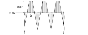
- FIG. 11 shows the valleys and peaks formed when the valleys and peaks formed by the first polishing step S61 and the second polishing step S62 are polished using the # 1000 polishing film. The outline is shown.
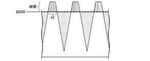
- FIG. 12 shows the valleys and peaks formed when the valleys and peaks formed by the first polishing step S61 and the second polishing step S62 are polished using the # 2000 polishing film. The outline is shown. In FIG. 11, the mountain portion of the portion indicated by “polishing” is scraped, whereas in FIG. 12, the peak portion of the portion indicated by “polishing” is scraped.
- the polishing film of # 1000 has a large amount of polishing of the mountain portion
- the polishing film of # 2000 has a small amount of polishing of the mountain portion. Therefore, the width of the peak portion in one mountain portion that affects the true contact area when the piston rod comes into contact with the oil seal is larger in the mountain portion width e2 in FIG. 12 than in the mountain portion width e1 in FIG. It gets narrower.
- the true contact area of the outer surface of the piston rod after polishing with the # 1000 polishing film is larger than the true contact area of the outer surface of the piston rod after polishing with the # 2000 polishing film.
- the depth of the valley portion forming the oil pool on the outer surface of the piston rod after polishing with the polishing film of # 2000 is for polishing of # 1000. It is deeper than the depth of the valley that constitutes the oil pool on the outer surface of the piston rod after polishing with a film.
- the surface of the sliding range A of the large diameter portion 21a of the piston rod 21 (on the surface of the chrome plating layer).
- a certain sliding surface A) has a protruding peak height Rpk of 0 ⁇ m or more and 0.04 ⁇ m or less (0 to 0 to 0), which is a characteristic evaluation parameter of the plateau structure surface described in JIS B 0671-2 and ISO 13565-2.
- the level difference Rk of the core part is 0.08 ⁇ m or more and 0.16 ⁇ m or less (0.08 to 0.16 ⁇ m)
- the protrusion valley depth Rvk is 0.06 ⁇ m or more and less than the plating thickness. It turned out that it was desirable to have a certain polished surface. As described above, when the chromium plating layer thickness is 20 ⁇ m, the protrusion valley depth Rvk is 0.06 ⁇ m or more and less than 20 ⁇ m.
- the smoothing roughness curve of the sliding surface A is obtained from the measured cross-sectional curve.
- the smoothness-roughness curve is represented by the measured raw data (cross-sectional curve) removed by a filter of the wavelength of the swell curve.
- ⁇ c 0.8 mm was used as the cutoff value ⁇ c used in this embodiment.
- the above-mentioned axial cross-section curve data is filtered by a phase compensation filter to calculate the first average line, and the lower part is removed from this first average line. Further, after the lower portion is removed, the same phase compensation filter is used for filtering to calculate the second average line, and the second average line is subtracted from the cross-sectional curve to obtain a smoothing roughness curve.
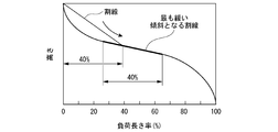
- FIG. 13 shows the relationship between the protruding peak portion, the protruding valley portion, the core portion, and the evaluation length ln with respect to the smoothing roughness curve. Further, FIG. 13 shows a load length ratio, a load curve corresponding to the smoothing roughness curve, an equivalent straight line, a protruding peak height (Rpk), a core level difference (Rk), and a protruding valley. The relationship between the part depth (Rvk) and the gentlest inclined straight line is shown.
- Mr1 indicates the load length ratio (percentage unit) at the point where the straight line separating the protruding peak portion and the core portion of the roughness curve intersects the load curve.
- Mr2 indicates the load length ratio (percentage unit) at the point where the straight line separating the protruding valley portion and the core portion of the roughness curve intersects the load curve.
- FIG. 14 shows the smoothing roughness curve obtained as described above.
- FIG. 15 shows a state in which the ratio of the load length of the contour curve element at the cutting level c to the evaluation length ln is obtained.
- FIG. 16 the position where the secant line of the load curve drawn by setting the difference ⁇ Mr of the load length ratio to 40% is the gentlest slope is obtained.
- the height of a right triangle equal to the cross-sectional area A1'of the protruding mountain portion is obtained, and Mr1 is used for the base.
- the load is calculated by totaling the widths of the protruding peaks while moving the cutting line for the smoothing roughness curve corresponding to the evaluation length from the upper end to the lower end.
- An equivalent straight line of 40% length is drawn with respect to this load curve, the intersection of the equivalent straight line and the vertical axis of 0% is set as the upper level of the core part, and the intersection of the equivalent straight line and the vertical line of 100% is below the core part.
- the difference between the upper limit level of the core portion and the lower limit level of the core portion is defined as the level difference Rk of the core portion.
- the area (equivalent triangle area A1') when the area surrounded by the apex and the upper level of the core portion of the load curve is equivalent to a triangle is obtained, and the height of the equivalent triangle is calculated as a protruding mountain.
- the part height is Rpk.
- the area (equivalent triangle area A2') when the area surrounded by the 100% vertical line and the load curve of the lower level of the core portion is equivalent to a triangle is obtained, and the height of the equivalent triangle is obtained.
- Rvk the protrusion valley depth
- the protruding peak height Rpk defined as described above is 0 ⁇ m or more and 0.04 ⁇ m or less (0 to 0.04 ⁇ m), and the level difference of the core portion.
- the polished surface has an Rk of 0.08 ⁇ m or more and 0.16 ⁇ m or less (0.08 to 0.16 ⁇ m), and a protruding valley depth Rvk of 0.06 ⁇ m or more and less than the plating thickness. From the test results described later, it is known that when the protrusion valley depth Rvk is less than 0.06 ⁇ m, the amount of change in frictional force and the frictional force increase. Therefore, the protrusion valley depth Rvk is 0.06 ⁇ m. It is desirable that it is the above.
- the level difference Rk of the core portion is 0.08 ⁇ m or more. Is desirable. From the test results described later, it is known that the amount of peeling of the oil seal increases when the protruding peak height Rpk exceeds 0.04 ⁇ m. Therefore, the protruding peak height Rpk must be 0.04 ⁇ m or less. desirable. From the test results described later, it is known that the amount of oil seal peeling increases when the level difference Rk of the core portion exceeds 0.16 ⁇ m. Therefore, the level difference Rk of the core portion should be 0.16 ⁇ m or less. desirable.
- polishing treatment step S6 was carried out according to the first to fourth polishing treatment steps S61 to 64 described above.
- a polishing treatment apparatus 40 having a drive rollers 41 and 42, a backup roller 43, a polishing film 44, and a pressure head 45 shown in FIG. 8 was used.
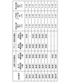
- the rotation speed of the drive roller 41 during polishing was set to 1400 rpm, and the pressing force by the pressurizing head 45 was set to 0.15 to 0.3 MPa. Further, in the first polishing treatment step S61 and the second polishing treatment step S62, any of the polishing films having the particle size 1, the particle size 2, and the particle size 3 shown in the order of FIG. 27 was used. Further, in the third polishing process step S63 and the fourth polishing process step S64, the polishing process was performed using any of the polishing films having the particle size 4, the particle size 5, and the particle size 6 shown in FIG. 27. In the first polishing treatment step S61 and the second polishing treatment step S62, groove formation effective mainly for holding the lubricating oil was performed. In the third polishing process step S63 and the fourth polishing process step S64, polishing processing was performed to form a plateau surface.
- the maximum frictional force at each frequency was measured and the change over time of the frictional force was evaluated using a fine amplitude exciter.
- the frequency is set to 0.2, 0.5, 1, 2, 5, 10, 15, 20, 30, 40 Hz
- the measurement area is the intermediate length of the piston rod ⁇ 1 mm
- the piston speed is 0. It was performed at .002 to 0.290 m / s.
- the maximum frictional force difference (PP) was defined as the difference between the maximum frictional force on the extension side and the maximum frictional force on the contraction side (Peak to Peak) of the suspension at each frequency.
- the amount of change in frictional force was the difference between the initial value of the test and the maximum frictional force (PP) after 3 cycles.
- break-in vibration (amplitude: 30 mm, frequency: 0.53 Hz, vibration time: 10 minutes) is performed, and then the frequency is applied at the frequency shown in FIG. 29.
- Shake (10 conditions). Similar tests were performed three times at 1 minute intervals.
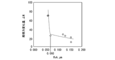
- FIG. 21 shows the results of obtaining the relationship between the protrusion valley depth Rvk and the maximum frictional force difference (PP).
- the maximum frictional force difference (PP) is the difference between the maximum frictional force on the extension side and the maximum frictional force on the contraction side (Peak to Peak) of the suspension at each frequency.
- FIG. 24 shows the result of obtaining the relationship between the level difference Rk of the core portion and the maximum frictional force difference (PP).
- the protrusion valley depth Rvk must be 0.06 ⁇ m or more in order to reduce the maximum frictional force difference (PP). From the results shown in FIG. 24, it was found that in order to reduce the maximum frictional force difference (PP), it is necessary to set the level difference Rk of the core portion to 0.08 ⁇ m or more. From the above results, by setting the level difference Rk of the core portion to 0.08 ⁇ m or more and the protrusion valley depth Rvk to 0.06 ⁇ m or more, an appropriate oil groove can be formed on the sliding surface of the piston rod. Therefore, it was found that the sliding surface on the outer side of the oil seal of the piston rod recovers quickly from the dry state to the wet (steady) state, and the compatibility between the oil and the piston rod can be improved.
- a cylinder device shock absorber having the structure shown in FIGS. 2 to 5 in an oilless state.
- the amount of seal wear was evaluated with an amplitude of ⁇ 1 mm, a frequency of 15 Hz, an intermediate length of the measurement region rod of ⁇ 1 mm, and a test cycle of 2700 times.
- the amount of seal wear was evaluated by observing the amount of oil seal adhering to the surface of the piston rod after the test with a laser microscope.
- FIG. 25 shows the relationship between the amount of oil seal adhered and the height of the protruding ridge Rpk.
- FIG. 26 shows the relationship between the amount of oil seal adhered and the level difference Rk of the core portion.
- the cylinder device of this embodiment is provided with a bottomed cylindrical cylinder, a seal member provided at an opening of the cylinder, and a protrusion from the opening of the cylinder, and slides against the seal member. It is equipped with a moving piston rod.
- the sliding surface of the piston rod has a chrome plating layer.
- the protrusion valley depth Rvk which is a characteristic evaluation parameter of the plateau structure surface described in JIS B 0671-2 and ISO 13565-2, is 0.06 ⁇ m or more and less than the plating thickness.
- the height Rpk of the protruding mountain portion is 0 ⁇ m or more and 0.04 ⁇ m or less, and the level difference Rk of the core portion is 0.08 ⁇ m or more and 0.16 ⁇ m or less.
- the method for manufacturing a piston rod of the same embodiment is a method for manufacturing a piston rod having a chrome-plated layer formed on a sliding surface, and includes a polishing treatment step performed after the chrome-plated layer is formed. Then, in the polishing treatment step, by polishing using the first polishing film, the protrusion valley depth Rvk, which is a characteristic evaluation parameter of the plateau structure surface described in JIS B 0671-2 and ISO 13565-2, is obtained.
- the protruding peak height Rpk which is the lubricity parameter of the plateau structure surface, is 0 ⁇ m or more and 0.04 ⁇ m or less, and the level difference Rk of the core part is 0.08 ⁇ m or more and 0.16 ⁇ m or less. It has a finish polishing process and;
- the method for manufacturing a piston rod according to (2) above may be as follows: In the initial polishing process, a polishing material having a coarse particle size of # 600 or less is used as the first polishing film. The initial polished surface is formed; in the finish polishing process, the plateau surface is formed by using a polishing material having a fine particle size of # 800 or more as the second polishing film. An abrasive having a particle size of # 120 or more and # 600 or less may be used as the first polishing film. Further, as the second polishing film, a polishing material having a particle size of # 800 or more and # 3000 or less may be used.
- the sliding surface of the piston rod has a suitable depth of the protruding valley portion, a height of the protruding peak portion, and a level difference of the core portion. Therefore, it has excellent wear resistance, has low aggression against the oil seal, can reduce the wear of the oil seal, and can reduce the change in sliding characteristics with time. Further, it is possible to provide a suspension device which has good familiarity from a dry state to a steady state and does not deteriorate the riding comfort of an automobile when applied to a piston rod for an automobile suspension device. Therefore, the industrial applicability is great.
Landscapes
- Engineering & Computer Science (AREA)
- Mechanical Engineering (AREA)
- General Engineering & Computer Science (AREA)
- Fluid-Damping Devices (AREA)
- Finish Polishing, Edge Sharpening, And Grinding By Specific Grinding Devices (AREA)
- Pistons, Piston Rings, And Cylinders (AREA)
- Sealing With Elastic Sealing Lips (AREA)
- Actuator (AREA)
- Electroplating Methods And Accessories (AREA)
Priority Applications (8)
| Application Number | Priority Date | Filing Date | Title |
|---|---|---|---|
| US17/909,505 US12576468B2 (en) | 2020-03-27 | 2021-03-11 | Cylinder device and method of manufacturing piston rod |
| DE112021001958.9T DE112021001958T5 (de) | 2020-03-27 | 2021-03-11 | Zylindervorrichtung und Verfahren zur Herstellung einer Kolbenstange |
| CN202180022054.6A CN115298455A (zh) | 2020-03-27 | 2021-03-11 | 缸体装置和活塞杆的制造方法 |
| JP2022509913A JP7407908B2 (ja) | 2020-03-27 | 2021-03-11 | 自動車用サスペンション装置のピストンロッドの製造方法 |
| MX2022011036A MX2022011036A (es) | 2020-03-27 | 2021-03-11 | Dispositivo de cilindro y metodo para fabricar un vastago del piston. |
| KR1020227020395A KR102776153B1 (ko) | 2020-03-27 | 2021-03-11 | 실린더 장치와 피스톤 로드의 제조 방법 |
| JP2023163852A JP7723053B2 (ja) | 2020-03-27 | 2023-09-26 | シリンダ装置 |
| JP2025127336A JP2025156432A (ja) | 2020-03-27 | 2025-07-30 | 緩衝器用ピストンロッドの製造方法 |
Applications Claiming Priority (2)
| Application Number | Priority Date | Filing Date | Title |
|---|---|---|---|
| JP2020057547 | 2020-03-27 | ||
| JP2020-057547 | 2020-03-27 |
Publications (1)
| Publication Number | Publication Date |
|---|---|
| WO2021193107A1 true WO2021193107A1 (ja) | 2021-09-30 |
Family
ID=77892039
Family Applications (1)
| Application Number | Title | Priority Date | Filing Date |
|---|---|---|---|
| PCT/JP2021/009810 Ceased WO2021193107A1 (ja) | 2020-03-27 | 2021-03-11 | シリンダ装置とピストンロッドの製造方法 |
Country Status (8)
| Country | Link |
|---|---|
| US (1) | US12576468B2 (https=) |
| JP (3) | JP7407908B2 (https=) |
| KR (1) | KR102776153B1 (https=) |
| CN (1) | CN115298455A (https=) |
| CZ (1) | CZ2022365A3 (https=) |
| DE (1) | DE112021001958T5 (https=) |
| MX (1) | MX2022011036A (https=) |
| WO (1) | WO2021193107A1 (https=) |
Cited By (3)
| Publication number | Priority date | Publication date | Assignee | Title |
|---|---|---|---|---|
| WO2023064093A1 (en) * | 2021-10-14 | 2023-04-20 | Caterpillar Inc. | Method and system for a cylinder liner |
| JPWO2023063109A1 (https=) * | 2021-10-15 | 2023-04-20 | ||
| WO2023068164A1 (ja) * | 2021-10-22 | 2023-04-27 | Kyb株式会社 | 摺動部材の製造方法、緩衝器の製造方法、摺動部材、緩衝器および乗り心地性調整方法 |
Families Citing this family (1)
| Publication number | Priority date | Publication date | Assignee | Title |
|---|---|---|---|---|
| JP7783660B2 (ja) | 2021-08-27 | 2025-12-10 | バイオアプリケーションズ インコーポレイテッド | アフリカ豚熱ウイルス由来抗原タンパク質を含むアフリカ豚熱の予防用ワクチン |
Citations (7)
| Publication number | Priority date | Publication date | Assignee | Title |
|---|---|---|---|---|
| JP2003286895A (ja) * | 2002-03-27 | 2003-10-10 | Nippon Piston Ring Co Ltd | 内周面に表面処理皮膜を有するシリンダライナ及びその加工方法 |
| JP2009293773A (ja) * | 2008-06-09 | 2009-12-17 | Honda Motor Co Ltd | 可変減衰力ダンパ及びその製造方法 |
| JP2011137492A (ja) * | 2009-12-28 | 2011-07-14 | Honda Motor Co Ltd | ベルト式無段変速機用プーリーの製造方法 |
| JP2014062490A (ja) * | 2012-09-21 | 2014-04-10 | Suzuki Motor Corp | シリンダボア内面の加工方法および加工装置 |
| JP2015161016A (ja) * | 2014-02-28 | 2015-09-07 | 日立オートモティブシステムズ株式会社 | 表面加工部品の製造方法および表面加工部品の製造装置 |
| JP2018084301A (ja) * | 2016-11-25 | 2018-05-31 | 内山工業株式会社 | オイルシール及びオイルシールの製造方法 |
| WO2018154716A1 (ja) * | 2017-02-24 | 2018-08-30 | 三菱電機株式会社 | ロータリー型圧縮機、及び、ロータリー型圧縮機の製造方法 |
Family Cites Families (10)
| Publication number | Priority date | Publication date | Assignee | Title |
|---|---|---|---|---|
| DE59307522D1 (de) * | 1993-07-14 | 1997-11-13 | Guenter Weber | Verfahren zum herstellen von kolben und kolbenstangen sowie zylindern für hydraulik- oder pneumatikaggregate |
| JP2004183862A (ja) * | 2002-12-06 | 2004-07-02 | Daido Metal Co Ltd | 油圧緩衝器 |
| JP2005213564A (ja) | 2004-01-29 | 2005-08-11 | Hitachi Ltd | シリンダ装置用ロッド、該ロッドを用いたシリンダ装置、該ロッドの製造方法及びめっき処理装置 |
| JP2013204748A (ja) | 2012-03-29 | 2013-10-07 | Hitachi Automotive Systems Ltd | 流体圧緩衝器 |
| JP5981193B2 (ja) | 2012-03-30 | 2016-08-31 | 日立オートモティブシステムズ株式会社 | めっき部品の製造方法およびシリンダ装置の製造方法 |
| WO2014145227A1 (en) * | 2013-03-15 | 2014-09-18 | Tech M3, Inc. | Wear resistant braking systems |
| CN109844292B (zh) * | 2016-10-20 | 2021-12-07 | 本田技研工业株式会社 | 具有滑动接触表面的构件 |
| JP2018154716A (ja) | 2017-03-16 | 2018-10-04 | 日清食品ホールディングス株式会社 | トリュフ風味付与剤 |
| US10816058B2 (en) * | 2018-03-16 | 2020-10-27 | Toyota Jidosha Kabushiki Kaisha | Torsional vibration damper and manufacturing method thereof |
| JP2020057547A (ja) | 2018-10-03 | 2020-04-09 | トヨタ自動車株式会社 | 電気機器 |
-
2021
- 2021-03-11 CN CN202180022054.6A patent/CN115298455A/zh active Pending
- 2021-03-11 WO PCT/JP2021/009810 patent/WO2021193107A1/ja not_active Ceased
- 2021-03-11 DE DE112021001958.9T patent/DE112021001958T5/de active Pending
- 2021-03-11 US US17/909,505 patent/US12576468B2/en active Active
- 2021-03-11 MX MX2022011036A patent/MX2022011036A/es unknown
- 2021-03-11 JP JP2022509913A patent/JP7407908B2/ja active Active
- 2021-03-11 KR KR1020227020395A patent/KR102776153B1/ko active Active
-
2022
- 2022-08-31 CZ CZ2022-365A patent/CZ2022365A3/cs unknown
-
2023
- 2023-09-26 JP JP2023163852A patent/JP7723053B2/ja active Active
-
2025
- 2025-07-30 JP JP2025127336A patent/JP2025156432A/ja active Pending
Patent Citations (7)
| Publication number | Priority date | Publication date | Assignee | Title |
|---|---|---|---|---|
| JP2003286895A (ja) * | 2002-03-27 | 2003-10-10 | Nippon Piston Ring Co Ltd | 内周面に表面処理皮膜を有するシリンダライナ及びその加工方法 |
| JP2009293773A (ja) * | 2008-06-09 | 2009-12-17 | Honda Motor Co Ltd | 可変減衰力ダンパ及びその製造方法 |
| JP2011137492A (ja) * | 2009-12-28 | 2011-07-14 | Honda Motor Co Ltd | ベルト式無段変速機用プーリーの製造方法 |
| JP2014062490A (ja) * | 2012-09-21 | 2014-04-10 | Suzuki Motor Corp | シリンダボア内面の加工方法および加工装置 |
| JP2015161016A (ja) * | 2014-02-28 | 2015-09-07 | 日立オートモティブシステムズ株式会社 | 表面加工部品の製造方法および表面加工部品の製造装置 |
| JP2018084301A (ja) * | 2016-11-25 | 2018-05-31 | 内山工業株式会社 | オイルシール及びオイルシールの製造方法 |
| WO2018154716A1 (ja) * | 2017-02-24 | 2018-08-30 | 三菱電機株式会社 | ロータリー型圧縮機、及び、ロータリー型圧縮機の製造方法 |
Cited By (7)
| Publication number | Priority date | Publication date | Assignee | Title |
|---|---|---|---|---|
| WO2023064093A1 (en) * | 2021-10-14 | 2023-04-20 | Caterpillar Inc. | Method and system for a cylinder liner |
| JPWO2023063109A1 (https=) * | 2021-10-15 | 2023-04-20 | ||
| WO2023063109A1 (ja) * | 2021-10-15 | 2023-04-20 | 京セラ株式会社 | 気密端子および圧縮機 |
| JP7701985B2 (ja) | 2021-10-15 | 2025-07-02 | 京セラ株式会社 | 気密端子および圧縮機 |
| WO2023068164A1 (ja) * | 2021-10-22 | 2023-04-27 | Kyb株式会社 | 摺動部材の製造方法、緩衝器の製造方法、摺動部材、緩衝器および乗り心地性調整方法 |
| JP2023062822A (ja) * | 2021-10-22 | 2023-05-09 | Kyb株式会社 | 摺動部材の製造方法、緩衝器の製造方法、摺動部材、緩衝器および乗り心地性調整方法 |
| JP7619925B2 (ja) | 2021-10-22 | 2025-01-22 | カヤバ株式会社 | 緩衝器用摺動部材の製造方法、緩衝器の製造方法、緩衝器用摺動部材および緩衝器 |
Also Published As
| Publication number | Publication date |
|---|---|
| JP2025156432A (ja) | 2025-10-14 |
| CN115298455A (zh) | 2022-11-04 |
| MX2022011036A (es) | 2022-10-13 |
| KR20220097525A (ko) | 2022-07-07 |
| JPWO2021193107A1 (https=) | 2021-09-30 |
| JP2023174706A (ja) | 2023-12-08 |
| JP7723053B2 (ja) | 2025-08-13 |
| DE112021001958T5 (de) | 2023-01-19 |
| JP7407908B2 (ja) | 2024-01-04 |
| US12576468B2 (en) | 2026-03-17 |
| KR102776153B1 (ko) | 2025-03-04 |
| US20230116767A1 (en) | 2023-04-13 |
| CZ2022365A3 (cs) | 2022-11-23 |
Similar Documents
| Publication | Publication Date | Title |
|---|---|---|
| WO2021193107A1 (ja) | シリンダ装置とピストンロッドの製造方法 | |
| KR102134742B1 (ko) | 주철제 실린더 라이너 및 내연 기관 | |
| KR101898049B1 (ko) | 조합 오일링 | |
| CN108026969A (zh) | 轴承构件以及使用其的振动衰减装置 | |
| JP4199500B2 (ja) | シリンダブロック | |
| JP2009216235A (ja) | 可変減衰力ダンパ及びその製造方法 | |
| JPS6121439A (ja) | シヨツクアブソ−バ | |
| RU2667557C2 (ru) | Механическая деталь, покрытая слоем аморфного углерода, для скольжения по другому менее твердому компоненту | |
| Shen et al. | Studies on friction and wear properties of surface produced by ultrasonic vibration-assisted milling | |
| CN112639307B (zh) | 曲轴及其制造方法 | |
| JP2009293773A (ja) | 可変減衰力ダンパ及びその製造方法 | |
| US20040206600A1 (en) | Hard-faced friction mating member | |
| KR102658650B1 (ko) | 슬라이딩 부재 | |
| Castro et al. | Analysis of the tribological performances of biodegradable hydraulic oils HEES and HEPR in the sliding of Cu–Zn/WC–CoCr alloys using the Stribeck curve | |
| KR102616390B1 (ko) | 슬라이딩 부재 | |
| JP2003343632A (ja) | 車両用の油圧緩衝器 | |
| WO2024166872A1 (ja) | 緩衝器 | |
| WO2023068164A1 (ja) | 摺動部材の製造方法、緩衝器の製造方法、摺動部材、緩衝器および乗り心地性調整方法 | |
| US6974143B2 (en) | Hydraulic shock absorber for vehicle | |
| JP7802635B2 (ja) | オイルリング、オイルリングの製造方法 | |
| JP7435803B2 (ja) | 溶射被膜及び該溶射被膜の製造方法 | |
| JPS5950465B2 (ja) | シリンダライナ オヨビ ソノホ−ニングホウホウ | |
| Kaleli et al. | Experimental investigation of the effects of engine cylinder honing as tribological aspect on performance, wear, and lubrication | |
| WO2024053640A1 (ja) | めっき部材およびその製造方法 | |
| CN117280138A (zh) | 扭转减振器以及用于得到该扭转减振器的涂料 |
Legal Events
| Date | Code | Title | Description |
|---|---|---|---|
| 121 | Ep: the epo has been informed by wipo that ep was designated in this application |
Ref document number: 21775091 Country of ref document: EP Kind code of ref document: A1 |
|
| ENP | Entry into the national phase |
Ref document number: 2022509913 Country of ref document: JP Kind code of ref document: A |
|
| ENP | Entry into the national phase |
Ref document number: 20227020395 Country of ref document: KR Kind code of ref document: A |
|
| 122 | Ep: pct application non-entry in european phase |
Ref document number: 21775091 Country of ref document: EP Kind code of ref document: A1 |
|
| WWG | Wipo information: grant in national office |
Ref document number: 17909505 Country of ref document: US |