WO2021192374A1 - 車両用空気調和装置 - Google Patents
車両用空気調和装置 Download PDFInfo
- Publication number
- WO2021192374A1 WO2021192374A1 PCT/JP2020/039070 JP2020039070W WO2021192374A1 WO 2021192374 A1 WO2021192374 A1 WO 2021192374A1 JP 2020039070 W JP2020039070 W JP 2020039070W WO 2021192374 A1 WO2021192374 A1 WO 2021192374A1
- Authority
- WO
- WIPO (PCT)
- Prior art keywords
- refrigerant
- air
- indoor
- vehicle
- detection result
- Prior art date
- Legal status (The legal status is an assumption and is not a legal conclusion. Google has not performed a legal analysis and makes no representation as to the accuracy of the status listed.)
- Ceased
Links
Images



Classifications
-
- B—PERFORMING OPERATIONS; TRANSPORTING
- B60—VEHICLES IN GENERAL
- B60H—ARRANGEMENTS OF HEATING, COOLING, VENTILATING OR OTHER AIR-TREATING DEVICES SPECIALLY ADAPTED FOR PASSENGER OR GOODS SPACES OF VEHICLES
- B60H1/00—Heating, cooling or ventilating devices
-
- B—PERFORMING OPERATIONS; TRANSPORTING
- B60—VEHICLES IN GENERAL
- B60H—ARRANGEMENTS OF HEATING, COOLING, VENTILATING OR OTHER AIR-TREATING DEVICES SPECIALLY ADAPTED FOR PASSENGER OR GOODS SPACES OF VEHICLES
- B60H1/00—Heating, cooling or ventilating devices
- B60H1/22—Heating, cooling or ventilating devices the heat source being other than the propulsion plant
-
- B—PERFORMING OPERATIONS; TRANSPORTING
- B61—RAILWAYS
- B61D—BODY DETAILS OR KINDS OF RAILWAY VEHICLES
- B61D27/00—Heating, cooling, ventilating, or air-conditioning
-
- F—MECHANICAL ENGINEERING; LIGHTING; HEATING; WEAPONS; BLASTING
- F24—HEATING; RANGES; VENTILATING
- F24F—AIR-CONDITIONING; AIR-HUMIDIFICATION; VENTILATION; USE OF AIR CURRENTS FOR SCREENING
- F24F7/00—Ventilation
-
- F—MECHANICAL ENGINEERING; LIGHTING; HEATING; WEAPONS; BLASTING
- F25—REFRIGERATION OR COOLING; COMBINED HEATING AND REFRIGERATION SYSTEMS; HEAT PUMP SYSTEMS; MANUFACTURE OR STORAGE OF ICE; LIQUEFACTION SOLIDIFICATION OF GASES
- F25B—REFRIGERATION MACHINES, PLANTS OR SYSTEMS; COMBINED HEATING AND REFRIGERATION SYSTEMS; HEAT PUMP SYSTEMS
- F25B1/00—Compression machines, plants or systems with non-reversible cycle
-
- F—MECHANICAL ENGINEERING; LIGHTING; HEATING; WEAPONS; BLASTING
- F25—REFRIGERATION OR COOLING; COMBINED HEATING AND REFRIGERATION SYSTEMS; HEAT PUMP SYSTEMS; MANUFACTURE OR STORAGE OF ICE; LIQUEFACTION SOLIDIFICATION OF GASES
- F25B—REFRIGERATION MACHINES, PLANTS OR SYSTEMS; COMBINED HEATING AND REFRIGERATION SYSTEMS; HEAT PUMP SYSTEMS
- F25B49/00—Arrangement or mounting of control or safety devices
- F25B49/02—Arrangement or mounting of control or safety devices for compression type machines, plants or systems
Definitions
- the present disclosure relates to a vehicle air conditioner that is mounted on a vehicle and air-conditions the interior of the vehicle.
- a vehicle air conditioner that air-conditions a vehicle interior by a refrigeration cycle that uses a carbon dioxide refrigerant.
- This vehicle air conditioner has a first room equipped with an indoor heat exchanger constituting a refrigeration cycle, a carbon dioxide concentration sensor, and a ventilation damper, and the carbon dioxide concentration is a preset reference value.
- the ventilation damper is opened to take in outside air and reduce the concentration of carbon dioxide.
- An object of the present disclosure is to provide an air conditioner for a vehicle capable of suppressing the outflow of the leaked refrigerant into the passenger compartment.
- the vehicle air conditioner according to the present disclosure is formed by partitioning the inside of a housing mounted on a vehicle, and includes a suction port and an air outlet leading to the passenger compartment of the vehicle, and a ventilation port leading to the outside of the vehicle. It is possible to switch between forward rotation and reverse rotation between the indoor unit room and the indoor heat exchanger that is located in the indoor unit room and exchanges heat between the refrigerant and air. Detects the state of the refrigerant and the indoor blower that forms an air flow in which the air in the passenger compartment that has flowed into the indoor unit compartment heads for the indoor heat exchanger and the air that has passed through the indoor heat exchanger flows out from the air outlet to the passenger compartment.
- the air outlet and the ventilation port are opened and the suction port is closed. It is characterized by being provided with a control unit that controls and switches the indoor blower to reverse rotation to form an air flow in which the air in the passenger compartment that has flowed into the indoor unit compartment from the air outlet flows out from the ventilation port to the outside of the vehicle. do.
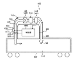
- FIG. It is a conceptual diagram which shows a part of the structure of the air conditioner for a vehicle which concerns on Embodiment 1.
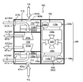
- FIG. It is a top view which shows the inside of the housing of the air conditioner for vehicles which concerns on Embodiment 1.
- FIG. It is a figure which shows the airflow formed in the housing of the vehicle air conditioner which concerns on Embodiment 1.
- FIG. It is a figure which shows the airflow formed in the housing of the vehicle air conditioner which concerns on Embodiment 1.
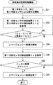
- FIG. It is a flowchart which shows the refrigerant leakage monitoring processing of the control part of the air conditioner for a vehicle which concerns on Embodiment 1.
- FIG. 1 It is a flowchart which shows the process flow of the emergency control of the control part of the air conditioner for a vehicle which concerns on Embodiment 1.
- FIG. It is a flowchart which shows the modification of the refrigerant leakage monitoring processing of the air conditioner for a vehicle which concerns on Embodiment 1.
- FIG. It is a top view which shows the modification of the air conditioner for a vehicle which concerns on Embodiment 1.
- FIG. It is a top view which shows the inside of the housing of the air conditioner for vehicles which concerns on Embodiment 2.
- FIG. It is a flowchart which shows the refrigerant leakage monitoring process of the control part of the air conditioner for a vehicle which concerns on Embodiment 2.
- FIG. 1 It is a flowchart which shows the refrigerant leakage monitoring processing of the control part of the air conditioner for a vehicle which concerns on Embodiment 3.
- FIG. It is a top view which shows the inside of the housing of the air conditioner for vehicles which concerns on Embodiment 4.
- FIG. It is a flowchart which shows the refrigerant leakage monitoring processing of the control part of the air conditioner for a vehicle which concerns on Embodiment 4.
- FIG. 1 is a conceptual diagram showing a part of the configuration of the vehicle air conditioner 800 according to the present embodiment.
- the vehicle air conditioner 800 shown in FIG. 1 is mounted on a vehicle 900 and air-conditions a vehicle compartment (cabin) 910, which is a space partitioned for a person to ride in the vehicle 900.
- a vehicle compartment (cabin) 910 which is a space partitioned for a person to ride in the vehicle 900.
- FIG. 1 is a concept in which some of the components are omitted and the position and the extending direction are different from the actual ones in order to facilitate the understanding of the function of the vehicle air conditioner 800. It is a figure. Details will be described later with reference to another figure.
- the vehicle air conditioner 800 includes a housing 700, an indoor heat exchanger 130, an indoor blower 310, a detector 500, a suction port damper 410, and a ventilation port damper 430.
- the control unit 600 is provided.
- the detector 500 detects the state of the refrigerant such as the concentration of the refrigerant or the flow rate of the refrigerant, and the detection result of the detector 500 is used to determine whether or not the refrigerant has leaked from the refrigeration cycle. Be done.
- the case where the detector 500 is the first refrigerant sensor 510 that detects the concentration of the refrigerant will be described.
- the housing 700 includes an indoor unit room 710, which is a space mounted on a vehicle and formed by partitioning the inside with a partition plate.
- an indoor heat exchanger 130, an indoor blower 310, and a first refrigerant sensor 510 are installed in the indoor unit room 710.
- the indoor unit room 710 includes a suction port 411 leading to the passenger compartment 910, an air outlet 421, and a ventilation port 431 leading to the outside of the vehicle 900.
- the “outside of the vehicle (outside the vehicle)" refers to the outside of the vehicle 900 and the housing 700.
- the suction port 411 and the outlet 421 are connected to the suction duct 920 and the outlet duct 930, which are ducts communicating with the passenger compartment 910, respectively.
- the indoor unit 710 communicates with the passenger compartment 910. Further, during normal operation in which the vehicle air conditioner 800 air-conditions the passenger compartment 910, the air in the passenger compartment 910 is sucked into the indoor unit 710 through the suction port 411, and the air conditioned in the indoor unit 710 is discharged. It is blown out to the passenger compartment 910 through the air outlet 421.
- the indoor heat exchanger 130 is a part of the refrigeration cycle device 100 that constitutes a refrigeration cycle using a refrigerant, and heat exchange is performed between the refrigerant flowing inside the refrigeration cycle and air.
- the refrigerant may be, for example, carbon dioxide gas, chlorofluorocarbon gas (R407C or the like), or any other refrigerant.
- the indoor blower 310 promotes heat exchange between the air in the passenger compartment 910 and the refrigerant flowing inside the indoor heat exchanger 130. Specifically, in the indoor blower 310, during the normal operation of the vehicle air conditioner 800, the air in the passenger compartment 910 that has flowed into the indoor unit compartment 710 from the suction port 411 heads toward the indoor heat exchanger 130, and the indoor heat exchanger The air that has passed through 130 forms an airflow AC that flows out from the outlet 421 to the passenger compartment 910 again. Further, the indoor blower 310 has a configuration capable of switching the rotation direction of the blades (not shown) to forward rotation or reverse rotation.
- the indoor blower 310 has a motor (not shown) capable of switching between forward rotation and reverse rotation, and the blades are driven by this motor. Further, the indoor blower 310 has wings having a shape such that the airflow AC is formed by rotating forward and the airflow is formed in the direction opposite to the direction of the airflow formed during the forward rotation by rotating in the reverse direction.
- the rotation of the indoor blower 310 is controlled by the control unit 600. During normal operation, the control unit 600 controls the indoor blower 310 so that the rotation is forward.
- the indoor blower 310 is realized by, for example, a sirocco fan.
- suction air RA the air flowing from the passenger compartment 910 into the indoor unit compartment 710 and heading toward the indoor heat exchanger 130
- blowout air SA the air that flows out from the indoor unit room 710 to the passenger compartment 910 after passing through the indoor heat exchanger 130
- the suction air RA flows from the passenger compartment 910 into the indoor unit compartment 710 through the suction duct 920 and the suction port 411.
- the blown air SA flows out from the indoor unit 710 to the passenger compartment 910 through the blowout port 421 and the blowout duct 930.
- the first refrigerant sensor 510 detects the concentration of the refrigerant in the indoor unit room 710 and outputs the detected result to the control unit 600.
- the first refrigerant sensor 510 has a sensitive portion (not shown) that causes a reaction according to the refrigerant concentration, and outputs a detection result of the refrigerant concentration based on the reaction at the sensitive portion.
- the suction port damper 410 is a damper provided in the suction port 411, and is the air forming the airflow AC from the passenger compartment 910 to the indoor unit room 710 through the suction port 411, that is, the interior of the suction air RA. It is possible to switch between an open state that allows inflow to the cabin 710 and a closed state that prevents the inflow. Further, the suction port damper 410 can adjust the flow rate of the suction air RA in the open state. The opening and closing of the suction port damper 410 is controlled by the control unit 600. Switching the open / closed state of the suction port damper 410 is equivalent to switching the open / closed state of the suction port 411.
- the ventilation port damper 430 is a damper provided in the ventilation port 431, and the air outflow (exhaust) of the indoor unit room 710 to the outside of the vehicle and the inflow of the outside air into the indoor unit room 710 (exhaust) through the ventilation port 431 (exhaust). It is possible to switch between an open state that allows inspiration) and a closed state that prevents this outflow and inflow. Further, the ventilation port damper 430 can adjust the flow rate of air passing through the ventilation port 431 in the open state. The opening and closing of the ventilation port damper 430 is controlled by the control unit 600. Switching the open / closed state of the ventilation port damper 430 is equivalent to switching the open / closed state of the ventilation port 431. Further, whether the air is discharged or taken in from the ventilation port 431 is determined by whether the pressure inside the indoor unit 710 is a negative pressure or a positive pressure.
- the control unit 600 controls the operations of the indoor blower 310, the first refrigerant sensor 510, the suction port damper 410, the ventilation port damper 430, and the refrigeration cycle device 100, and during normal operation, the suction port damper 410 and ventilation.
- the mouth damper 430 is opened, and the indoor blower 310 is controlled to rotate in the forward direction. Further, during normal operation, a refrigerant leak monitoring process for monitoring whether or not a refrigerant has leaked is performed, and when it is determined that the refrigerant has leaked, emergency control is performed.
- the refrigerant leak monitoring process is a process of repeatedly executing a refrigerant leak determination for determining whether or not a refrigerant has leaked from the refrigeration cycle device 100 based on the refrigerant concentration detected by the first refrigerant sensor 510.
- the emergency control is a process of controlling the operation of the indoor blower 310, the suction port damper 410, and the ventilation port damper 430 to suppress the outflow of the refrigerant into the vehicle interior 910. Details of the refrigerant leak monitoring process and emergency control will be described later.
- the control unit 600 is arranged inside the housing 700 or behind the ceiling of the vehicle interior 910.
- the control unit 600 that realizes the refrigerant leakage monitoring process and the emergency control may be composed of, for example, a microcomputer that reads and executes a program, or a CPU (Central Processing Unit), or an ASIC (Application Specific Integrated Circuit). Alternatively, it may be configured with dedicated hardware such as FPGA (Field Programmable Gate Array).
- FIG. 2 is a plan view showing the inside of the housing 700 of the vehicle air conditioner 800 according to the present embodiment. Further, FIG. 2 shows an airflow AC formed when the suction port damper 410 and the ventilation port damper 430 are opened and the indoor blower 310 is switched to forward rotation.
- the refrigeration cycle device 100 housed in the housing 700 constitutes a refrigeration cycle independently of the first refrigeration cycle device 100a constituting the refrigeration cycle and the first refrigeration cycle device 100a. It has two refrigeration cycle devices 100b.
- the first refrigeration cycle device 100a includes a first compressor 110a for compressing the refrigerant, a first outdoor heat exchanger 120a for condensing the compressed refrigerant, and a first expander for expanding the condensed refrigerant (not shown). ),
- the first chamber heat exchanger 130a that evaporates the expanded refrigerant, and the first accumulator 140a that separates the liquid from the refrigerant that has passed through the first chamber heat exchanger 130a and returns the gas to the first compressor 110a. include.
- the first refrigerating cycle device 100a includes a first refrigerant pipe 150a through which a refrigerant flows.
- the first refrigerant pipe 150a is a closed circuit through which the refrigerant flows by connecting the first compressor 110a, the first outdoor heat exchanger 120a, the first expander, the first indoor heat exchanger 130a, and the first accumulator 140a. To configure.
- the second refrigeration cycle device 100b includes a second compressor 110b that compresses the refrigerant, a second outdoor heat exchanger 120b that condenses the compressed refrigerant, and a second expander that expands the condensed refrigerant (not shown). ), A second chamber heat exchanger 130b that evaporates the expanded refrigerant, and a second accumulator 140b that separates the liquid from the refrigerant that has passed through the second chamber heat exchanger 130b and returns the gas to the second compressor 110b. include. Further, the second refrigeration cycle device 100b includes a second refrigerant pipe 150b in which a refrigerant flows inside.
- the second refrigerant pipe 150b is a closed circuit through which the refrigerant flows by connecting the second compressor 110b, the second outdoor heat exchanger 120b, the second expander, the second indoor heat exchanger 130b, and the second accumulator 140b. To configure.
- the housing 700 also includes an outdoor unit room 720, which is a space formed by partitioning the inside with a partition plate. Since the indoor unit room 710 and the outdoor unit room 720 are airtightly configured with each other, no gas flow occurs between the indoor unit room 710 and the outdoor unit room 720.
- the first indoor unit room 711 in which the first indoor heat exchanger 130a and the first heater 200a are arranged, and the second indoor unit room 711 in which the second indoor heat exchanger 130b and the second heater 200b are arranged are arranged. It is divided into an indoor unit room 712 and a third indoor unit room 713 in which the first indoor blower 310a, the second indoor blower 310b, and the first refrigerant sensor 510 are arranged.
- the first indoor unit room 711 and the second indoor unit room 712 are provided at positions opposite to each other with the third indoor unit room 713 in between.
- the first indoor unit room 711 and the third indoor unit room 713 communicate with each other through the first indoor unit blower 310a.
- the second indoor unit 712 and the third indoor unit 713 communicate with each other through the second indoor blower 310b.
- the first indoor unit room 711 includes a first suction port 411a and a first ventilation port 431a.
- the second indoor unit 712 includes a second suction port 411b and a second ventilation port 431b.
- the third indoor unit room 713 includes a first outlet 421a and a second outlet 421b.
- the indoor heat exchanger 130 shown in FIG. 1 is configured by the first indoor heat exchanger 130a and the second indoor heat exchanger 130b. Further, the first suction port 411a and the second suction port 411b constitute the suction port 411 shown in FIG. Further, the first outlet 421a and the second outlet 421b constitute the outlet 421 shown in FIG.
- the first ventilation port 431a is arranged at a position where the airflow AC passes in the first indoor unit room 711.
- the second ventilation port 431b is arranged at a position in the second indoor unit room 712 where the airflow AC passes. Further, the first ventilation port 431a is arranged at a position facing the first indoor blower 310a, and the first indoor heat exchanger 130a is arranged between the first ventilation port 431a and the first indoor blower 310a.
- the second ventilation port 431b is arranged at a position facing the second indoor blower 310b, and the second indoor heat exchanger 130b is arranged between the second ventilation port 431b and the second indoor blower 310b.
- the first ventilation port 431a and the second ventilation port 431b constitute the ventilation port 431 shown in FIG.
- the "position through which the airflow AC passes" is preferably near the path of the airflow AC, but may be any position as long as it is the indoor unit room 710 through which the airflow AC passes.
- the first indoor blower 310a promotes heat exchange between the first indoor heat exchanger 130a and the air in the passenger compartment 910 shown in FIG. Specifically, in the first chamber blower 310a, the suction air RA that has flowed into the first chamber unit 711 from the first suction port 411a passes through the first chamber heat exchanger 130a, and then is first blown as blown air SA. An airflow AC is formed from the exit 421a to the passenger compartment 910 shown in FIG.
- the first chamber blower 310a is arranged at a position downstream of the first chamber heat exchanger 130a with respect to the direction of the flow of the airflow AC formed by itself.
- the second indoor blower 310b promotes heat exchange between the second indoor heat exchanger 130b and the air in the passenger compartment 910 shown in FIG. Specifically, in the second chamber blower 310b, the suction air RA that has flowed into the second chamber unit 712 from the second suction port 411b passes through the second chamber heat exchanger 130b, and then is second blown as blown air SA. An airflow AC is formed from the exit 421b back to the passenger compartment 910 shown in FIG.
- the second chamber blower 310b is arranged at a position downstream of the second chamber heat exchanger 130b with respect to the direction of the flow of the airflow AC formed by itself.
- FIG. 1 is configured by the first indoor blower 310a and the second indoor blower 310b. Further, in FIG. 1, for easy understanding, the airflow AC formed by the first indoor blower 310a and the airflow AC formed by the second indoor blower 310b are shown as one airflow AC.
- the first heater 200a is arranged on the path of the airflow AC formed by the first indoor blower 310a. Specifically, the first heater 200a is arranged between the first chamber heat exchanger 130a and the first chamber blower 310a. The first heater 200a heats the air passing through itself.
- the second heater 200b is arranged on the path of the airflow AC formed by the second indoor blower 310b. Specifically, the second heater 200b is arranged between the second chamber heat exchanger 130b and the second chamber blower 310b. The second heater 200b heats the air passing through itself.
- the first suction port damper 410a is a damper provided in the first suction port 411a, and has an open state that allows the suction air RA to flow into the first indoor unit room 711 and a closed state that prevents the inflow. It is possible to switch to. Further, the first suction port damper 410a can adjust the air flow rate in the open state.
- the second suction port damper 410b is a damper provided in the second suction port 411b, and has an open state that allows the suction air RA to flow into the second indoor unit room 712 and a closed state that prevents the inflow. It is possible to switch to. Further, the second suction port damper 410b can adjust the air flow rate in the open state.
- the suction port damper 410 shown in FIG. 1 is configured by the first suction port damper 410a and the second suction port damper 410b.
- the first ventilation port damper 430a is a damper provided in the first ventilation port 431a, and allows the outflow of air from the first indoor unit room 711 to the outside of the vehicle and the inflow of outside air into the first indoor unit room 711. It is possible to switch between an open state where the air is open and a closed state where the outflow and the inflow are blocked. Further, the first ventilation port damper 430a can adjust the flow rate of air in the open state.
- the second ventilation port damper 430b is a damper provided in the second ventilation port 431b, and allows the outflow of air from the second indoor unit 712 to the outside of the vehicle and the inflow of outside air into the second indoor unit 712. It is possible to switch between an open state where the air is open and a closed state where the outflow and the inflow are blocked. Further, the second ventilation port damper 430b can adjust the flow rate of air in the open state.
- the ventilation port damper 430 shown in FIG. 1 is configured by the first ventilation port damper 430a and the second ventilation port damper 430b. Further, in the following, the air flowing in from the outside of the vehicle through the ventilation port 431 is referred to as an outside air FA.
- the ventilation port damper 430 is arranged at a position facing the indoor blower 310. Outside air flows into the cabin 710. Further, when the rotation is switched to the reverse rotation, the outside air flows out from the indoor unit room 710 to the outside of the vehicle through the ventilation port 431.
- the first refrigerant sensor 510 is arranged at a position downstream of the first chamber heat exchanger 130a on the path of the airflow AC formed when the first chamber blower 310a is rotated in the forward direction.
- the first refrigerant sensor 510 detects the concentration of the refrigerant at the arranged position and outputs the detection result to the control unit 600 shown in FIG.
- the arrangement position of the first refrigerant sensor 510 is not limited to this, and may be the first indoor unit room 711 or the second indoor unit room 712 as long as the refrigerant concentration in the indoor unit room 710 can be detected. However, it may be located at another position in the third indoor unit room 713.
- the outdoor unit room 720 includes an outdoor blower 320, a first compressor 110a, a second compressor 110b, a first outdoor heat exchanger 120a, a second outdoor heat exchanger 120b, a first accumulator 140a, and a second accumulator 140b. Be placed.
- the outdoor blower 320 promotes heat exchange between the first outdoor heat exchanger 120a and the second outdoor heat exchanger 120b and the air outside the vehicle. Specifically, the outdoor blower 320 forms an air flow (not shown) in which the outside air passes through the first outdoor heat exchanger 120a and the second outdoor heat exchanger 120b and returns to the outside of the vehicle again.
- FIG. 3 and 4 are views showing an air flow formed when the first indoor blower 310a and the second indoor blower 310b are switched to reverse rotation.
- FIG. 3 shows a case where the first suction port damper 410a, the second suction port damper 410b, the first ventilation port damper 430a, and the second ventilation port damper 430b are controlled in the open state.
- FIG. 4 shows a case where the first suction port damper 410a and the second suction port damper 410b are controlled to be in the closed state, and the first ventilation port damper 430a and the second ventilation port damper 430b are controlled to be in the open state.
- the airflow AC_R flowing in the direction opposite to the direction of the airflow AC formed at the time of the forward rotation is formed.
- the control unit 600 controls the damper 410a for the first suction port to the open state and the damper 430a for the first ventilation port to the open state and switches the first indoor blower 310a to the reverse rotation
- the first air outlet After the air in the passenger compartment 910 that has flowed from the 421a into the third indoor unit chamber 713 passes through the first indoor heat exchanger 130a, an air flow AC_R that flows out from the first suction port 411a to the passenger compartment 910 again is formed.
- the air in the first indoor unit room 711 flows out of the vehicle from the first ventilation port 431a.
- the air that flows from the passenger compartment 910 into the third indoor unit room 713 and heads for the first indoor heat exchanger 130a is sucked in and passes through the first indoor heat exchanger 130a.
- the air that flows out from the first indoor unit room 711 to the passenger compartment 910 is called blowout air SA_R, and the air that flows out from the first ventilation port 431a is called exhaust air EA. Since the second indoor blower 310b is controlled in the same manner as the first indoor blower 310a to form the same air flow, the description thereof is omitted here.
- FIG. 3 and 4 is the open / closed state of the first suction port damper 410a.
- the air flow from the first indoor unit 711 to the passenger compartment 910 is not formed. Therefore, in FIG. 4, the blown air SA_R and the exhaust air EA shown in FIG. 3 become the exhaust air EA2 and flow out to the outside of the vehicle.
- control unit 600 controls the open / closed state of the first suction port damper 410a and the first ventilation port damper 430a and the rotation direction of the first indoor blower 310a, thereby forming the inside of the housing 700.
- the airflow can be changed. Further, by forming the airflow AC2 shown in FIG. 4, an airflow from the passenger compartment 910 to the first indoor unit 711 is formed at the first outlet 421a without a damper, so that the airflow from the third indoor unit 713 is formed. The outflow of air to the passenger compartment 910 can be suppressed.
- the refrigerant existing in the first indoor unit 710a and the third indoor unit 713 is discharged to the outside of the vehicle as exhaust air EA2, the refrigerant concentrations in the first indoor unit 711 and the third indoor unit 713 are increased. The rise can be suppressed.
- FIG. 5 is a flowchart showing a processing flow of the refrigerant leakage monitoring process.
- FIG. 6 is a flowchart showing a processing flow of emergency control.
- the control unit 600 causes the first refrigerant sensor 510 to start detecting the concentration of the refrigerant (step S11). After that, the first refrigerant sensor 510 repeatedly detects the concentration of the refrigerant in real time at the installed position.
- the control unit 600 acquires the detection result Cs from the first refrigerant sensor 510 (step S12), and determines the rate of increase of the detection result Cs and a predetermined value indicating that the refrigerant has leaked from the refrigeration cycle device 100. Compare with the threshold Th (step S13).
- the threshold Th is 10000 [ppm / h], but the threshold Th is not particularly limited.
- the "rate of increase in detection result Cs" refers to the difference between the value of the current detection result and the value of the previous detection result, or a physical quantity proportional to the difference.
- the "value of the current detection result” is the value of the detection result Cs (t) at time t
- the “value of the previous detection result” is the detection result Cs (t-) at time t-1 one sampling cycle before. It means the value of 1).
- the initial value of the detection result Cs is set to zero.
- step S13 NO
- the control unit 600 determines that the refrigerant has not leaked from the refrigeration cycle device 100. Then, the control unit 600 returns to step S12 again in order to continue monitoring whether or not the refrigerant has leaked.
- the loop of step S12 and step S13 is repeated every sampling cycle of detection by the first refrigerant sensor 510.
- the detection sampling period of the first refrigerant sensor 510 is preferably 15 seconds or less, more preferably 10 seconds or less, and even more preferably 3 seconds or less.
- step S13 when the rate of increase in the detection result Cs exceeds the threshold value Th (step S13: YES), the control unit 600 determines that the refrigerant has leaked from the refrigeration cycle device 100. Then, the control unit 600 starts emergency control for suppressing an increase in the concentration of the refrigerant in the vehicle interior 910 (step S14).
- the process of step S13 corresponds to the above-mentioned refrigerant leakage determination.
- the emergency control will be specifically described.
- the control unit 600 first stops the air conditioning (step S21). Specifically, the control unit 600 stops the first compressor 110a and the second compressor 110b shown in FIG. As a result, the circulation of the refrigerant in the refrigeration cycle device 100 is stopped, so that the deterioration of the refrigerant leakage is suppressed.
- the control unit 600 also stops the outdoor blower 320 shown in FIG.
- the control unit 600 switches the first suction port damper 410a and the second suction port damper 410b shown in FIG. 2 to the closed state, and the first ventilation port damper 430a and the second suction port damper 410b shown in FIG.
- the ventilation port damper 430b switched to the open state
- the first indoor blower 310a and the second indoor blower 310b shown in FIG. 2 are switched to reverse rotation (step S22).
- the exhaust air EA2 is discharged to the outside of the vehicle through the first ventilation port 431a and the second ventilation port 431sb.
- the refrigerant leaking from the refrigerating cycle device 100 and existing in the indoor unit room 710 is discharged to the outside of the vehicle as exhaust air EA2 without flowing out to the cabin 910, so that the concentration of the refrigerant in the indoor unit room 710 increases. It is suppressed.
- the airflow from the passenger compartment 910 to the indoor unit 710 is formed at the first outlet 421a and the second outlet 421b without dampers, the outflow of the refrigerant from the indoor unit 710 to the passenger compartment 910 is suppressed. Will be done.
- carbon dioxide gas is used as the refrigerant when the housing 700 is installed on the roof of the vehicle 900, since carbon dioxide is heavier than air, there is a high possibility that the refrigerant will flow out from the indoor unit 710 to the vehicle compartment 910. ..
- the first suction port damper 410a and the second suction port damper 410b are switched to the closed state, and the first chamber blower 310a and the second chamber are replaced.
- the blower 310b By rotating the blower 310b in the reverse direction, the outflow of the refrigerant to the passenger compartment 910 is suppressed.
- the first indoor blower 310a and the second indoor blower 310b also play a role of drawing outside air into the passenger compartment 910 by rotating in the reverse direction. Specifically, the air pressure in the passenger compartment 910 decreases as the exhaust air EA2 is discharged. As the air pressure drops, outside air flows into the passenger compartment 910 through a ventilation port (not shown) provided in the passenger compartment 910 or a gap such as a door or a window of the passenger compartment 910. As a result, even if the refrigerant flows out to the passenger compartment 910, an increase in the concentration of the refrigerant in the passenger compartment 910 can be suppressed.
- step S14 the control unit 600 acquires the detection result Cs from the first refrigerant sensor 510 again (step S15), and whether the rate of increase of the detection result Cs is equal to or less than the threshold value Th. It is determined whether or not (step S16).
- the threshold value Th is a value so small that it can be considered that the leakage of the refrigerant from the refrigeration cycle device 100 has been completed. That is, step S16 represents a determination as to whether or not to terminate the emergency control (hereinafter, referred to as an termination determination).
- the threshold values Th used in step S13 and step S16 may be the same value or different values.
- step S15 may be started after a predetermined time has elapsed from the completion of step S14.
- emergency control is started, the environment in the indoor unit room changes drastically. Therefore, the operation of the refrigerant leakage monitoring process may become unstable. Therefore, the time required from the start of the emergency control to the stabilization of the operation of the refrigerant leakage monitoring process is set as a predetermined time. As a result, the refrigerant leakage monitoring process operates normally.
- step S16 NO
- the control unit 600 returns to step S15 and returns to the emergency because the leakage of the refrigerant from the refrigeration cycle device 100 has not been completed yet.
- the loop of steps S15 and S16 is repeated every sampling cycle of detection by the first refrigerant sensor 510.
- step S16 when the rate of increase in the detection result Cs is equal to or less than the threshold value Th (step S16: YES), the control unit 600 can consider that the leakage of the refrigerant from the refrigeration cycle device 100 has been completed, so that the emergency control can be performed. It ends (step S17). Specifically, the control unit 600 controls the first suction port damper 410a and the second suction port damper 410b shown in FIG. 2 in the closed state, and the first indoor blower 310a and the first chamber blower 310a shown in FIG. 2 Stop the indoor blower 310b. Further, it is preferable to keep controlling the first ventilation port damper 430a and the second ventilation port damper 430b shown in FIG.
- control unit 600 may end the emergency control after a predetermined time has elapsed after determining that the leakage of the refrigerant has been completed.
- the predetermined time may be the time required to exhaust the air in the indoor unit 710 to the outside of the vehicle.
- the configuration for determining the start and end of refrigerant leakage using the rate of increase in the detection result Cs has been described, but the detection result Cs is used instead of the rate of increase in the detection result Cs for refrigerant leakage. It may be configured to determine the start and end.
- the threshold value for determining the start of the refrigerant leakage is a value large enough to be regarded as the refrigerant leaking. Further, the threshold value for determining the end of the refrigerant leakage is a value small enough to be considered that the refrigerant has not leaked.
- control unit 600 completes the refrigerant leakage monitoring process.
- the control unit 600 does not restart the air conditioning operation until the repair of the refrigeration cycle device 100 is completed.
- the vehicle air conditioner 800 is formed by partitioning the inside of a housing mounted on the vehicle, and has a suction port and an air outlet leading to the passenger compartment of the vehicle, and ventilation leading to the outside of the vehicle.
- An indoor unit room equipped with a mouth and an indoor heat exchanger that is arranged in the indoor unit room and exchanges heat between the refrigerant and air can be switched between forward rotation and reverse rotation.
- the state of the refrigerant and the indoor blower that forms an air flow in which the air in the passenger compartment that has flowed into the indoor unit from the suction port heads for the indoor heat exchanger and the air that has passed through the indoor heat exchanger flows out from the air outlet to the passenger compartment.
- the control unit that forms an air flow in which the air in the passenger compartment that has flowed into the indoor unit compartment from the air outlet flows out to the outside of the vehicle through the ventilation port by controlling the closed state and switching the indoor blower to the reverse rotation.
- the suction port 411 and the air outlet 421, which are openings that communicate the indoor unit 710 and the passenger compartment 910 the suction port 411 is controlled to be closed, and the airflow from the passenger compartment 910 to the indoor unit 710 flows.
- the refrigerant can be positively exhausted to the outside of the vehicle without providing a blower dedicated to exhaust. can. Further, even if the outlet 421 is not provided with the outlet damper, it is possible to suppress the leakage of the refrigerant to the vehicle interior 910.
- the configuration in which the end determination of the emergency control is performed based on the detection result Cs of the first refrigerant sensor 510 after the start of the emergency control has been described, but the configuration in which the end determination of the emergency control is not performed may be performed. ..
- a processing flow in which the end determination of the emergency control is not performed will be described with reference to FIG. 7.
- the control unit 600 does not perform the processes of steps S15 to S17 of FIG. 5, and the refrigerant leakage monitoring process continues in the state where the emergency control is continued. To finish. In this case, the control unit 600 continues the emergency control until the end operation is performed by the repair person or the like. As a result, even when there is a refrigerant that is not discharged to the outside of the vehicle and remains in the indoor unit, the outflow of the refrigerant to the vehicle compartment 910 can be suppressed.
- first outlet 421a and the second outlet 421b are not provided with dampers, and the first outlet 421a and the second outlet 421b are always maintained in an open state.
- first outlet 421a may be provided with the first outlet damper 420a
- second outlet 421b may be provided with the second outlet damper 420b.
- a configuration including the first air outlet damper 420a and the second air outlet damper 420b will be described with reference to FIG.
- FIG. 8 is a plan view showing the housing 700 of the vehicle air conditioner 800 including the first air outlet damper 420a and the second air outlet damper 420b. All the dampers are in the open state, and the first indoor blower. The airflow AC formed when the 310a and the second chamber blower 310b are controlled to rotate in the forward direction is shown. Further, FIG. 8 is the same as the housing 700 shown in FIG. 2 except that the damper 420a for the first outlet and the damper 420b for the second outlet are provided.
- the points different from the configuration shown in FIG. 2 will be mainly described.
- the first air outlet damper 420a is a damper provided at the first air outlet 421a, and is the air forming the airflow AC from the first indoor unit 711 to the passenger compartment 910 via the first air outlet 421a, that is. It is possible to switch between an open state that allows the outflow of the blown air SA to the cabin 910 and a closed state that prevents the outflow. Further, the first air outlet damper 420a can adjust the flow rate of air in the open state. The opening and closing of the first air outlet damper 420a is controlled by the control unit 600. Switching the open / closed state of the first air outlet damper 420a is equivalent to switching the open / closed state of the first air outlet 421a.
- the second air outlet damper 420b is a damper provided at the second air outlet 421b, and is the air forming the airflow AC from the first indoor unit 711 to the passenger compartment 910 via the second air outlet 421b, that is. It is possible to switch between an open state that allows the outflow of the blown air SA to the cabin 910 and a closed state that prevents the outflow. Further, the second air outlet damper 420b can adjust the air flow rate in the open state. The opening and closing of the second outlet damper 420b is controlled by the control unit 600. Switching the open / closed state of the second outlet damper 420b is equivalent to switching the open / closed state of the second outlet 421b. Further, the first outlet damper 420a and the second outlet damper 420b constitute the outlet damper 420 shown in FIG. 1.
- control unit 600 controls all the dampers in the open state, and controls the first chamber blower 310a and the second chamber blower 310b to rotate in the forward direction.
- the airflow AC as shown in the figure is formed, and the same actions and effects as those of the present embodiment can be obtained.
- the control unit 600 closes the first suction port damper 410a and the second suction port damper 410b, the first ventilation port damper 430a, the second ventilation port damper 430b, and the first blow.
- the outlet damper 420a and the second outlet damper 420b controlled in the open state, the first chamber blower 310a and the second chamber blower 310b are controlled to rotate in the reverse direction.
- the same actions and effects as those of the present embodiment can be obtained.
- the control unit 600 controls the first suction port damper 410a, the second suction port damper 410b, the first outlet damper 420a, and the second outlet damper 420b in a closed state.
- the first chamber blower 310a and the second chamber blower 310b are stopped.
- the damper may be switched to the closed state.
- the indoor unit 710 and the passenger compartment 910 can be disconnected.
- the outflow of the refrigerant to the vehicle interior 910 can be suppressed.
- a configuration is described in which a first refrigerant sensor 510 is provided as the detector 500, and the detection result of the first refrigerant sensor 510 is used to determine whether or not the refrigerant has leaked.
- the present embodiment is different from the first embodiment in that the detector 500 is further provided with the second refrigerant sensor 520. Specifically, the detection of the first refrigerant sensor arranged at a position downstream of the indoor heat exchanger 130 and the second refrigerant sensor arranged at a position upstream of the indoor heat exchanger 130 with respect to the flow direction of the airflow AC. The difference is that the result is used to determine whether or not the refrigerant has leaked.
- a configuration different from that of the first embodiment will be mainly described.
- FIG. 9 is a plan view showing the inside of the housing 700 of the vehicle air conditioner 800 according to the present embodiment.
- FIG. 9 shows an airflow AC formed when the suction port damper 410 and the ventilation port damper 430 are opened and the indoor blower 310 is switched to forward rotation.
- the vehicle air conditioner 800 further includes a second refrigerant sensor 520 arranged in the first indoor unit room 711 in addition to the first refrigerant sensor 510.
- the second refrigerant sensor 520 detects the concentration of the refrigerant at a position upstream of the first chamber heat exchanger 130a on the path of the airflow AC formed by the first chamber blower 310a.
- the second refrigerant sensor 520 has the same configuration as the first refrigerant sensor 510.
- control unit 600 shown in FIG. 1 uses the detection result of the first refrigerant sensor 510 and the detection result of the second refrigerant sensor 520 to repeat the above-mentioned refrigerant leakage determination in real time. Perform monitoring processing.
- the control unit 600 shown in FIG. 1 uses the detection result of the first refrigerant sensor 510 and the detection result of the second refrigerant sensor 520 to repeat the above-mentioned refrigerant leakage determination in real time. Perform monitoring processing.
- FIG. 10 is a flowchart showing a processing flow of the control unit 600 of the vehicle air conditioner 800 according to the second embodiment.
- the control unit 600 causes the first refrigerant sensor 510 and the second refrigerant sensor 520 to start detecting the concentration of the refrigerant (step S31). After that, the first refrigerant sensor 510 and the second refrigerant sensor 520 repeatedly detect the concentration of the refrigerant in real time at each position.
- the control unit 600 acquires the detection result Cs from the first refrigerant sensor 510 and the detection result Cr from the second refrigerant sensor 520 (step S32). Then, the control unit 600 subtracts the detection result Cr of the second refrigerant sensor 520 from the detection result Cs of the first refrigerant sensor 510, and the value (Cs—Cr) of the result and the predetermined first threshold Th1 By comparison with the above, it is determined whether or not the refrigerant has leaked from the refrigeration cycle device 100 (step S33). The control unit 600 acquires the detection result Cs of the first refrigerant sensor 510 and the detection result Cr of the second refrigerant sensor 520 in real time, and the detection result Cs (t) detected at the same time t. The difference from Cr (t) (Cs (t) -Cr (t)) is calculated.
- the refrigerant when the refrigerant does not leak from the refrigeration cycle device 100, the refrigerant is formed between the second refrigerant sensor 520 and the first refrigerant sensor 510 on the path of the airflow AC formed by the first chamber blower 310a. There is no factor that increases the concentration of. Therefore, the detection result Cs of the first refrigerant sensor 510 and the detection result Cr of the second refrigerant sensor 520 show the same or close values. Therefore, the difference (Cs—Cr) is zero or a small value.
- the detection result Cs of the first refrigerant sensor 510 when the refrigerant does not leak. The concentration of the leaked refrigerant is added.
- the detection result Cr of the second refrigerant sensor 520 located upstream of the first chamber heat exchanger 130a and the first refrigerant pipe 150a shows the concentration derived from the leaked refrigerant. Has not been reflected yet. Therefore, the difference (Cs—Cr) becomes a large value.
- control unit 600 compares the value of the difference (Cs—Cr) with the first threshold value Th1 representing the increment of the concentration of the refrigerant in the air constituting the airflow AC due to the leakage of the refrigerant. Can detect leaks.
- step S33 NO
- the control unit 600 has the detection result Cs of the first refrigerant sensor 510 and the detection result Cr of the second refrigerant sensor 520. Is the same as or close to, so it is determined that the refrigerant has not leaked from the refrigeration cycle device 100. Then, the control unit 600 returns to step S32 again in order to continue monitoring whether or not the refrigerant has leaked.
- the loop of steps S32 and S33 is repeated every sampling cycle of detection by the first refrigerant sensor 510 and the second refrigerant sensor 520.
- step S33 when the difference (Cs—Cr) value exceeds the first threshold value Th1 (step S33: YES), the control unit 600 adds the concentration of the leaked refrigerant to the detection result Cs of the first refrigerant sensor 510. Therefore, it is determined that the refrigerant has leaked from the refrigeration cycle device 100. Therefore, the control unit 600 starts emergency control for suppressing an increase in the concentration of the refrigerant in the vehicle interior 910 (step S34).
- the specific contents of the emergency control are as shown in FIG.
- the control unit 600 again acquires the detection result Cs from the first refrigerant sensor 510 (step S35), and compares the detection result Cs of the first refrigerant sensor 510 with the predetermined second threshold value Th2 (step S35).
- the second threshold value Th2 is a value so small that it can be considered that the leakage of the refrigerant from the refrigeration cycle device 100 has been completed.
- the control unit 600 may determine the end of the refrigerant leakage by using the detection result Cr of the second refrigerant sensor 520 instead of the detection result Cs of the first refrigerant sensor 510.
- step S36 NO
- the control unit 600 has not completed the leakage of the refrigerant from the refrigeration cycle device 100, so that the emergency The process returns to step S35 in order to continue the control.
- the loop of steps S35 and S36 is repeated every sampling cycle of detection by the first refrigerant sensor 510.
- step S36 when the detection result Cs of the first refrigerant sensor 510 is equal to or less than the second threshold value Th2 (step S36: YES), the control unit 600 can consider that the leakage of the refrigerant from the refrigeration cycle device 100 has been completed. Therefore, the emergency control is terminated (step S37).
- the end determination of the emergency control may be performed based on the detection result Cr of the second refrigerant sensor 520.
- the control unit 600 can detect the leakage of the refrigerant at an early stage and with high accuracy based on the value of the difference (Cs—Cr).
- the control unit 600 subtracts the detection result Cr of the second refrigerant sensor 520 from the detection result Cs of the first refrigerant sensor 510 in step S33, so that the first refrigerant sensor 510 From the detection result Cs of, the concentration of carbon dioxide derived from the exhaled breath of the person in the passenger compartment 910 can be canceled. That is, even if the concentration of carbon dioxide derived from the exhaled breath of a person fluctuates due to the fluctuation of the occupancy rate in the passenger cabin 910, the influence of the fluctuation is the detection result Cs of the first refrigerant sensor 510 and the second refrigerant sensor 520.
- FIG. 11 is a flowchart showing a processing flow of the control unit 600 of the vehicle air conditioner 800 according to the third embodiment. Steps S31, S32, S34, and S37 in the figure perform the same processing as the steps having the same number as described above.
- the control unit 600 freezes by comparing the rate of increase of the difference (Cs—Cr) with the predetermined third threshold value Th3. It is determined whether or not the refrigerant has leaked from the cycle device 100 (step S41).
- the "difference (Cs-Cr) increase rate" is the value of the difference (Cs (t) -Cr (t)) at time t and the difference (Cs (t-1)) at time t-1 one sampling cycle before.
- the difference (Cs—Cr) value hardly changes with time, so that the increase rate of the difference (Cs—Cr) becomes zero or a value close to zero. ..
- the rate of increase of the difference (Cs—Cr) is a large value because it represents the severity of the leakage of the refrigerant. Therefore, when the rate of increase in the difference (Cs—Cr) is equal to or greater than the third threshold value Th3 indicating that the refrigerant is leaking from the refrigeration cycle device 100 (step S41: YES), the control unit 600 has step S34. Proceed to.
- step S41: NO when the rate of increase of the difference (Cs—Cr) is less than the third threshold value Th3 (step S41: NO), the control unit 600 cannot say that the refrigerant has leaked from the refrigeration cycle device 100. Return to S32.
- the control unit 600 compares the rate of increase in the detection result Cs of the first refrigerant sensor 510 with the predetermined fourth threshold value Th4 to obtain the refrigerant. It is determined whether or not the leakage is completed (step S42).
- the “rate of increase in Cs” is the difference (Cs) between the value of the detection result Cs (t) at the time t and the value of the detection result Cs (t-1) at the time t-1 one sampling cycle before. (T) -Cs (t-1)), or a physical quantity proportional to the difference thereof.
- step S42 When the leakage of the refrigerant is ending, the rate of increase in the amount of leakage of the refrigerant shows a negative value. Therefore, when the rate of increase in Cs is equal to or less than the negative fourth threshold value Th4 indicating that the leakage of the refrigerant is ending (step S42: YES), the control unit 600 proceeds to step S37 to increase Cs. If the rate is greater than the fourth threshold Th4 (step S42: NO), the process returns to step S35.
- Other configurations and effects are the same as in the second embodiment.
- the control unit 600 of the vehicle air conditioner 800 of the present embodiment determines whether or not the refrigerant has leaked based on the rate of increase in the difference between the detection result of the first refrigerant sensor and the detection result of the second refrigerant sensor. do. Thereby, it is possible to detect that the refrigerant is leaking from the refrigeration cycle device 100.
- FIG. 12 is a plan view showing the inside of the housing 700 of the vehicle air conditioner 800 according to the present embodiment.
- FIG. 12 shows an airflow AC formed when the suction port damper 410 and the ventilation port damper 430 are opened and the indoor blower 310 is switched to forward rotation.
- the vehicle air conditioner 800 is a current sensor that detects a current value supplied to a first compressor 110a that compresses the refrigerant instead of the first refrigerant sensor 510 and the second refrigerant sensor 520.
- 530 is provided.
- the current sensor 530 detects the current value supplied to the first compressor 110a and outputs the detected result to the control unit 600.
- the current sensor 530 is arranged in the outdoor unit room 720, but may be arranged outside the outdoor unit room 720 as long as it can detect the current value supplied to the first compressor 110a.
- control unit 600 shown in FIG. 1 performs the above-mentioned refrigerant leakage monitoring process using the detection result Ic of the current sensor 530.
- the control unit 600 controls the first compressor 110a so that the rotation speed becomes constant. Further, when the flow rate of the refrigerant flowing inside the first refrigeration cycle device 100a decreases, the resistance of the refrigerant decreases, and as a result, the current value required to drive the first compressor 110a decreases. Therefore, by monitoring the change in the current value supplied to the first compressor 110a, it is possible to detect the leakage of the refrigerant in the first refrigeration cycle device 100a. The same applies to the leakage of the refrigerant in the second refrigeration cycle device 100b.
- FIG. 13 is a flowchart showing a processing flow of the control unit 600 of the vehicle air conditioner 800 according to the fourth embodiment.
- the control unit 600 causes the current sensor 530 to start detecting the current value supplied to the first compressor 110a (step S51). After that, the current sensor 530 repeatedly detects the current value supplied to the first compressor 110a in real time.
- the control unit 600 acquires the detection result Ic from the current sensor 530 (step S52), and determines the rate of decrease of the detection result Ic and a predetermined value indicating that the refrigerant has leaked from the first refrigeration cycle device 100a. Compare with the fifth threshold Th5 (step S53).
- the "decrease rate of the detection result Ic” refers to the difference between the value of the previous detection result and the value of the current detection result, or a physical quantity proportional to the difference.
- the "value of the current detection result” is the value of the detection result Ic (t) at time t
- the "value of the previous detection result” is the detection result Ic (t-) at time t-1 one sampling cycle before. It means the value of 1).
- the initial value of the detection result Ic is set to zero.
- step S53 NO
- the control unit 600 determines that the refrigerant has not leaked from the first refrigeration cycle device 100a. Then, the control unit 600 returns to step S52 again in order to continue monitoring whether or not the refrigerant has leaked.
- the loop of step S52 and step S53 is repeated every sampling cycle of detection by the current sensor 530.
- step S53 determines that the refrigerant has leaked from the first refrigeration cycle device 100a. Therefore, the control unit 600 starts the emergency control for suppressing the increase in the concentration of the refrigerant in the vehicle interior 910 (step S54).
- the specific contents of the emergency control are as shown in FIG.
- the control unit 600 After starting the emergency control as described above (step S54), the control unit 600 acquires the detection result Ic from the current sensor 530 again (step S55), and whether the rate of decrease of the detection result Ic is the fifth threshold value Th5 or less. Whether or not it is determined (step S56).
- the fifth threshold value Th5 is a value so small that it can be considered that the leakage of the refrigerant from the first refrigeration cycle device 100a has been completed.
- the fifth threshold value Th5 used in step S53 and step S56 may have the same value or different values.
- step S56 NO
- the control unit 600 has not yet completed the leakage of the refrigerant from the first refrigeration cycle device 100a, so that step S55 Return to and continue emergency control.
- the loop of step S55 and step S56 is repeated every sampling cycle of detection by the current sensor 530.
- step S56 when the rate of decrease of the detection result Ic is equal to or less than the fifth threshold value Th5 (step S56: YES), the control unit 600 can consider that the leakage of the refrigerant from the first refrigeration cycle device 100a has been completed. , The emergency control is terminated (step S57).
- control unit 600 completes the refrigerant leakage monitoring process.
- the configuration in which the current sensor 530 detects the current value of the first compressor 110a has been described, but the current sensor 530 may be configured to detect the current value of the second compressor 110b.
- the configuration may be such that the current values of the 1 compressor 110a and the 2nd compressor 110b are detected.
- the leakage of the refrigerant is detected based on the decrease in the flow rate of the refrigerant in the refrigeration cycle.
- the leakage of the refrigerant can be detected with high accuracy regardless of the position where the leakage of the refrigerant has occurred and the position of the detector that detects the state of the refrigerant.
- the leakage of the refrigerant is detected based on the decrease of the refrigerant flowing in the refrigeration cycle device 100.
- the leakage of the refrigerant can be detected with high accuracy regardless of the position where the refrigerant has leaked and the position of the detector that detects the state of the refrigerant.
- the vehicle air conditioner 800 according to the first to third embodiments can be modified as described below.
- the second embodiment it is determined whether or not the refrigerant has leaked based on the value of the difference (Cs—Cr), and in the third embodiment, whether or not the refrigerant has leaked based on the rate of increase of the difference (Cs—Cr).
- the physical quantity used for determining whether or not the refrigerant has leaked is not limited to this.
- the detection result Cs or the value of Cr itself, or any physical quantity depending on Cs or Cr can be used to determine whether or not the refrigerant has leaked.
- the vehicle on which the housing 700 is installed is not limited to trains, bullet trains, monorails, and other railway vehicles including vehicles traveling along the track, but is not limited to trains, buses, and other automobiles. May be good.
- the housing 700 may be arranged on the roof of the vehicle 900 or may be arranged under the floor of the vehicle 900.
- 100 refrigeration cycle device 100a first refrigeration cycle device, 100b second refrigeration cycle device, 110a first compressor, 110b second compressor, 120a first outdoor heat exchanger, 120b second outdoor heat exchanger, 130 indoor heat Exchanger, 130a 1st room heat exchanger, 130b 2nd room heat exchanger, 140a 1st accumulator, 140b 2nd accumulator, 150a 1st refrigerant pipe, 150b 2nd refrigerant pipe, 200a 1st heater, 200b 2nd heater , 310 Indoor Blower, 310a 1st Indoor Blower, 310b 2nd Indoor Blower, 320 Outdoor Blower, 410 Suction Port Damper, 410a 1st Suction Port Damper, 410b 2nd Suction Port Damper, 420 Air Outlet Damper, 420a 1st outlet damper, 420b 2nd outlet damper, 430 ventilation port damper, 430a 1st ventilation port damper, 430b 2nd ventilation port damper, 500 detector, 510 1st refrigerant sensor, 520 2
Landscapes
- Engineering & Computer Science (AREA)
- Mechanical Engineering (AREA)
- Physics & Mathematics (AREA)
- Thermal Sciences (AREA)
- General Engineering & Computer Science (AREA)
- Chemical & Material Sciences (AREA)
- Combustion & Propulsion (AREA)
- Air Conditioning Control Device (AREA)
- Air-Conditioning For Vehicles (AREA)
Priority Applications (1)
| Application Number | Priority Date | Filing Date | Title |
|---|---|---|---|
| JP2022509230A JPWO2021192374A1 (https=) | 2020-03-27 | 2020-10-16 |
Applications Claiming Priority (2)
| Application Number | Priority Date | Filing Date | Title |
|---|---|---|---|
| JP2020057276 | 2020-03-27 | ||
| JP2020-057276 | 2020-03-27 |
Publications (1)
| Publication Number | Publication Date |
|---|---|
| WO2021192374A1 true WO2021192374A1 (ja) | 2021-09-30 |
Family
ID=77891694
Family Applications (1)
| Application Number | Title | Priority Date | Filing Date |
|---|---|---|---|
| PCT/JP2020/039070 Ceased WO2021192374A1 (ja) | 2020-03-27 | 2020-10-16 | 車両用空気調和装置 |
Country Status (2)
| Country | Link |
|---|---|
| JP (1) | JPWO2021192374A1 (https=) |
| WO (1) | WO2021192374A1 (https=) |
Cited By (4)
| Publication number | Priority date | Publication date | Assignee | Title |
|---|---|---|---|---|
| CN114714852A (zh) * | 2022-03-25 | 2022-07-08 | 浙江银轮机械股份有限公司 | 车用空调主机及汽车 |
| US20230398829A1 (en) * | 2022-06-13 | 2023-12-14 | Hyundai Motor Company | Air-conditioning device and system having an integrated heat exchanger |
| WO2024252670A1 (ja) * | 2023-06-09 | 2024-12-12 | 三菱電機株式会社 | 外気処理ユニットおよび空気調和機 |
| EP4606606A4 (en) * | 2022-10-18 | 2025-12-03 | Mitsubishi Electric Corp | AIR CONDITIONING SYSTEM FOR RAIL VEHICLES |
Citations (8)
| Publication number | Priority date | Publication date | Assignee | Title |
|---|---|---|---|---|
| JPS5854904U (ja) * | 1981-10-12 | 1983-04-14 | 三菱重工業株式会社 | 自動車用空調機 |
| JPS62138654A (ja) * | 1985-12-12 | 1987-06-22 | Isuzu Motors Ltd | 車両用燃焼式ヒ−タのガス漏れ検出装置 |
| WO2000059748A1 (fr) * | 1999-04-02 | 2000-10-12 | Bosch Automotive Systems Corporation | Dispositif de securite pour systeme de conditionnement d'air de vehicule |
| JP2004196063A (ja) * | 2002-12-17 | 2004-07-15 | Japan Climate Systems Corp | 車両用空調装置 |
| JP2005178428A (ja) * | 2003-12-16 | 2005-07-07 | Calsonic Kansei Corp | 車両用空調装置 |
| JP2009241892A (ja) * | 2008-03-31 | 2009-10-22 | Toyota Boshoku Corp | 車室内空気管理装置 |
| JP2009298274A (ja) * | 2008-06-12 | 2009-12-24 | Mitsubishi Electric Corp | 車両用換気空調装置 |
| JP2012136159A (ja) * | 2010-12-27 | 2012-07-19 | Mitsubishi Electric Corp | 鉄道車両用空調装置及び鉄道車両 |
Family Cites Families (2)
| Publication number | Priority date | Publication date | Assignee | Title |
|---|---|---|---|---|
| JP2000006800A (ja) * | 1998-06-19 | 2000-01-11 | Hitachi Ltd | 車両用換気装置 |
| EP2716480B1 (en) * | 2011-06-01 | 2020-02-12 | Mitsubishi Electric Corporation | Vehicle air conditioner |
-
2020
- 2020-10-16 JP JP2022509230A patent/JPWO2021192374A1/ja active Pending
- 2020-10-16 WO PCT/JP2020/039070 patent/WO2021192374A1/ja not_active Ceased
Patent Citations (8)
| Publication number | Priority date | Publication date | Assignee | Title |
|---|---|---|---|---|
| JPS5854904U (ja) * | 1981-10-12 | 1983-04-14 | 三菱重工業株式会社 | 自動車用空調機 |
| JPS62138654A (ja) * | 1985-12-12 | 1987-06-22 | Isuzu Motors Ltd | 車両用燃焼式ヒ−タのガス漏れ検出装置 |
| WO2000059748A1 (fr) * | 1999-04-02 | 2000-10-12 | Bosch Automotive Systems Corporation | Dispositif de securite pour systeme de conditionnement d'air de vehicule |
| JP2004196063A (ja) * | 2002-12-17 | 2004-07-15 | Japan Climate Systems Corp | 車両用空調装置 |
| JP2005178428A (ja) * | 2003-12-16 | 2005-07-07 | Calsonic Kansei Corp | 車両用空調装置 |
| JP2009241892A (ja) * | 2008-03-31 | 2009-10-22 | Toyota Boshoku Corp | 車室内空気管理装置 |
| JP2009298274A (ja) * | 2008-06-12 | 2009-12-24 | Mitsubishi Electric Corp | 車両用換気空調装置 |
| JP2012136159A (ja) * | 2010-12-27 | 2012-07-19 | Mitsubishi Electric Corp | 鉄道車両用空調装置及び鉄道車両 |
Cited By (5)
| Publication number | Priority date | Publication date | Assignee | Title |
|---|---|---|---|---|
| CN114714852A (zh) * | 2022-03-25 | 2022-07-08 | 浙江银轮机械股份有限公司 | 车用空调主机及汽车 |
| US20230398829A1 (en) * | 2022-06-13 | 2023-12-14 | Hyundai Motor Company | Air-conditioning device and system having an integrated heat exchanger |
| US12291077B2 (en) * | 2022-06-13 | 2025-05-06 | Hyundai Motor Company | Air-conditioning device and system having an integrated heat exchanger |
| EP4606606A4 (en) * | 2022-10-18 | 2025-12-03 | Mitsubishi Electric Corp | AIR CONDITIONING SYSTEM FOR RAIL VEHICLES |
| WO2024252670A1 (ja) * | 2023-06-09 | 2024-12-12 | 三菱電機株式会社 | 外気処理ユニットおよび空気調和機 |
Also Published As
| Publication number | Publication date |
|---|---|
| JPWO2021192374A1 (https=) | 2021-09-30 |
Similar Documents
| Publication | Publication Date | Title |
|---|---|---|
| WO2021192374A1 (ja) | 車両用空気調和装置 | |
| JP5127922B2 (ja) | 車両用空調システム | |
| KR102703182B1 (ko) | 차량용 공조 시스템 제어방법 | |
| JP6708170B2 (ja) | 車両用空調装置 | |
| JP4184777B2 (ja) | 車両用空調装置 | |
| JP2000296710A (ja) | 空気調和ユニット及び車両用空気調和装置 | |
| JP2009241892A (ja) | 車室内空気管理装置 | |
| WO2000022355A1 (fr) | Dispositif de climatisation | |
| WO2018230278A1 (ja) | 車両用空気調和装置及び車両用空気調和装置の空気調和方法 | |
| JP6583245B2 (ja) | 車両用空調装置 | |
| CN105705399A (zh) | 车用空调装置及包括该装置的铁道车辆 | |
| JP3980189B2 (ja) | 自動車用冷暖房装置 | |
| WO2021144907A1 (ja) | 車両用空調装置 | |
| JP7558430B2 (ja) | 車両用空調装置 | |
| CN110382267A (zh) | 车辆用空调控制装置 | |
| JP4042556B2 (ja) | 空調装置 | |
| JPH0820227A (ja) | 電気自動車用空調装置 | |
| JP2000016232A (ja) | 車両の安全装置 | |
| JP5164871B2 (ja) | 車両用空調装置 | |
| JPH06156060A (ja) | 空調装置 | |
| CN115556541B (zh) | 车辆空调设备、空调设备控制方法和系统 | |
| JP2008094340A (ja) | 車両用空調装置 | |
| JP2008281317A (ja) | 空調装置 | |
| KR20100022693A (ko) | 차량용 공조장치의 제어방법 | |
| JP2005178406A (ja) | 車両用空調装置の可変インテーク制御装置 |
Legal Events
| Date | Code | Title | Description |
|---|---|---|---|
| 121 | Ep: the epo has been informed by wipo that ep was designated in this application |
Ref document number: 20928005 Country of ref document: EP Kind code of ref document: A1 |
|
| ENP | Entry into the national phase |
Ref document number: 2022509230 Country of ref document: JP Kind code of ref document: A |
|
| NENP | Non-entry into the national phase |
Ref country code: DE |
|
| 122 | Ep: pct application non-entry in european phase |
Ref document number: 20928005 Country of ref document: EP Kind code of ref document: A1 |