WO2021192066A1 - バルーン型電極カテーテル - Google Patents
バルーン型電極カテーテル Download PDFInfo
- Publication number
- WO2021192066A1 WO2021192066A1 PCT/JP2020/013169 JP2020013169W WO2021192066A1 WO 2021192066 A1 WO2021192066 A1 WO 2021192066A1 JP 2020013169 W JP2020013169 W JP 2020013169W WO 2021192066 A1 WO2021192066 A1 WO 2021192066A1
- Authority
- WO
- WIPO (PCT)
- Prior art keywords
- balloon
- tip
- lumen
- type electrode
- fluid
- Prior art date
- Legal status (The legal status is an assumption and is not a legal conclusion. Google has not performed a legal analysis and makes no representation as to the accuracy of the status listed.)
- Ceased
Links
Images


Classifications
-
- A—HUMAN NECESSITIES
- A61—MEDICAL OR VETERINARY SCIENCE; HYGIENE
- A61B—DIAGNOSIS; SURGERY; IDENTIFICATION
- A61B18/00—Surgical instruments, devices or methods for transferring non-mechanical forms of energy to or from the body
- A61B18/04—Surgical instruments, devices or methods for transferring non-mechanical forms of energy to or from the body by heating
- A61B18/12—Surgical instruments, devices or methods for transferring non-mechanical forms of energy to or from the body by heating by passing a current through the tissue to be heated, e.g. high-frequency current
- A61B18/14—Probes or electrodes therefor
Definitions
- the present invention relates to a balloon-type electrode catheter for performing high-frequency ablation therapy.
- an outer tube catheter shaft
- a balloon connected to the tip of the outer tube and an outer tube
- balloon-type electrode catheters intravascular ablation devices
- Inner tube guide wire lumen
- lumen tube supply lumen
- a lumen tube inserted into the lumen of the outer tube to drain the fluid supplied to the balloon and a surface electrode provided on the outer surface of the balloon are introduced (below). See Patent Document 1).
- the balloon constituting the balloon-type electrode catheter described in Patent Document 1 has an expansion portion that expands and contracts and a neck portion formed at both ends thereof, and the proximal end side neck portion is fixed to the outer tube.
- the tip side neck is fixed to the inner tube (guide wire lumen).
- the fluid supplied to the inside of the balloon by the lumen tube is circulated inside the balloon and is circulated from the lumen tube (return lumen).
- the lumen tube return lumen
- a balloon-type electrode that can perform ablation treatment over a wide range for lesions such as tumors and has an excellent cooling effect inside the balloon and, by extension, the tissue surrounding the surface electrode.
- a catheter an outer tube having a central lumen and a plurality of sublumens arranged around the central lumen, an energizing connector arranged on the proximal end side of the outer tube, an expansion part that expands and contracts, and continuous ends thereof.
- the base end side neck portion is fixed to the tip end portion of the outer tube, and the expansion portion includes the tip end portion of the outer tube, so that the tip end side of the outer tube is provided.
- At least one of the sublumens of the outer tube is a fluid supply sublumen that allows the fluid to flow in order to supply the fluid to the inside of the balloon, and at least one of the sublumens of the outer tube.
- One is a fluid discharge sublumen that circulates the fluid in order to discharge the fluid supplied to the inside of the balloon from the inside of the balloon, and the fluid supply sublumen and the fluid discharge sublumen.
- One of the openings of the expansion portion is located closer to the tip side than the intermediate position in the axial direction of the expansion portion, and the other opening of the fluid supply sublumen and the fluid discharge sublumen is of the expansion portion.
- a balloon-type electrode catheter located at or near the proximal end has been proposed by the applicant (see Patent Document 2 below).
- the opening of either the fluid supply sublumen or the fluid discharge sublumen is located on the distal end side of the axially intermediate position of the extension portion, and the other. Even after the balloon is expanded, the opening is located at or near the proximal end of the expansion, that is, the fluid supply port and the fluid discharge port are displaced axially from each other. Since an axial flow of the fluid is formed and the fluid can flow inside the balloon, the inside of the balloon and, by extension, the tissue around the surface electrode can be sufficiently cooled.
- An object of the present invention is that a wide range of cauterization treatments can be performed on lesions such as tumors, and as compared with conventional balloon-type electrode catheters, the cooling effect inside the balloon and, by extension, the tissue around the surface electrode It is an object of the present invention to provide a balloon type electrode catheter having an excellent cooling effect.
- the balloon-type electrode catheter of the present invention is a balloon-type electrode catheter for performing high-frequency ablation treatment.
- the catheter tube includes a circular tubular portion extending in the proximal direction from a position at or near the proximal end of the expansion portion.
- a substance that extends from the position of the base end of the expansion portion or its vicinity to the inside of the expansion portion in the tip direction, and the tip surface thereof is located on the tip side of the intermediate position in the axial direction of the expansion portion. It has a semicircular tubular part and The area ratio of each of the main lumens to the cross section of the circular tubular portion is 20% or more.
- One of the main lumens is a fluid supply lumen that circulates the fluid in order to supply the fluid inside the balloon.
- the other of the main lumens is a fluid discharge lumen for circulating the fluid in order to discharge the fluid supplied to the inside of the balloon from the inside of the balloon.
- One of the sublumens of the catheter tube is a lumen for inserting the lead wire.
- the fluid supply lumen is disposed inside the circular tubular portion and the substantially semicircular tubular portion and opens at the tip surface of the substantially semicircular tubular portion.
- the fluid discharge lumen is arranged inside the circular tubular portion and is open at the tip end surface of the circular tubular portion.
- an opening of the fluid supply lumen is formed on the tip surface of a substantially semicircular tubular portion located closer to the tip side than the axial intermediate position of the expansion portion, and the opening of the fluid discharge lumen is the base of the expansion portion.
- the fluid supply lumen and the fluid discharge lumen each consist of a main lumen having a large cross-sectional area that occupies 20% or more of the cross section of the circular tubular portion of the catheter tube, the amount of fluid supplied to the inside of the balloon and the balloon.
- the amount of fluid discharged from the inside that is, the flow rate of the fluid circulating inside the balloon can be significantly increased as compared with the conventional one.
- the cooling effect inside the balloon and, by extension, the cooling effect of the tissue around the surface electrode are excellent.
- the area ratio of each of the main lumens to the cross section of the circular tubular portion is 25% or more.
- the cross section of the main lumen is elliptical.
- two main lumens having a large area can be arranged in the cross section of the circular tubular portion, and one main lumen having a large area can be arranged in the cross section of the semicircular tubular portion. Can be placed.
- the substantially semicircular tubular portion is radially from the central axis of the balloon so that the substantially semicircular tubular portion and the reinforcing shaft do not interfere with each other. It is preferable that the substantially semicircular tubular portion and the reinforcing shaft are adhesively fixed while being displaced.
- the balloon-type electrode catheter having such a configuration, it is possible to prevent the substantially semicircular tubular portion from interfering with the reinforcing shaft, and since both are adhesively fixed, good pushability is exhibited. be able to.
- the expansion portion of the balloon includes a cylindrical portion, a distal cone portion extending from the tip of the cylindrical portion to the base end of the distal neck portion, and the cylindrical portion. It consists of a base end side cone part extending from the base end of the shaped part to the tip end of the base end side neck part.
- the tip surface of the substantially semicircular tubular portion is located inside the tip of or near the tip of the cylindrical portion.
- the base end surface of the reinforcing shaft is preferably located inside the base end of the cylindrical portion or its vicinity.
- the reinforcing shaft is made of a PEEK resin tube, and resin is embedded in at least a part in the axial direction inside the tip and / or the PEEK resin tube. It is preferable that the flow of the fluid is blocked.
- the resin is embedded inside the tip portion of the tip tip and the base end portion of the PEEK resin tube.
- the highly rigid PEEK resin tube can exert a sufficient reinforcing effect and prevent fluid from leaking from the tip opening of the tip.
- the tip of the surface electrode extends to the outer surface of the tip or the neck on the tip side.
- a metal ring mounted on the tip or the neck on the tip side and electrically connected to the surface electrode is provided by fixing the tip of the surface electrode to the outer peripheral surface thereof.
- the tip of the conductor is connected to the inner peripheral surface of the metal ring, extends inside the balloon and to the sublumen of the catheter tube, and its base end is connected to the energizing connector. Is preferable.
- the surface electrode formed on the outer surface of the balloon can be electrically connected to the current-carrying connector via the metal ring and the conducting wire, so that the surface electrode can be connected to the surface electrode.
- a high-frequency current can be reliably applied.
- the tip side neck portion of the balloon to which the metal ring is attached is a neck portion fixed to the tip tip, and the outer diameter is much smaller than that of the proximal end side neck portion fixed to the catheter tube.
- the outer diameter of the metal ring attached to the distal neck portion can be made smaller than the outer diameter of the catheter tube or the proximal neck portion.
- the metal ring does not get caught in the opening of the sheath or endoscope to be used, and the balloon-type electrode catheter can be inserted into the lumen of the sheath or endoscope. Is not impaired.
- the surface electrodes are formed so as to extend along the axial direction of the balloon, and are arranged at equal angular intervals along the circumferential direction of the balloon. It is preferable that the tip portions of the strip-shaped electrodes are fixed to the outer peripheral surface of the metal ring.
- each of the plurality of strip-shaped electrodes formed at equal intervals along the circumferential direction of the balloon is electrically connected to the energizing connector via a metal ring and a conducting wire. Therefore, a high-frequency current can be evenly applied to each of the plurality of strip-shaped electrodes so that the vessel or the tissue around it can be connected along the circumferential direction of the vessel. It can be uniformly ablated.
- the temperature sensor is arranged on the tube wall of the balloon.
- the surface electrode formed on the outer surface of the balloon other than the cylindrical portion may be insulated and coated. As a result, cauterization can be performed only on the cylindrical portion of the balloon.
- the balloon-type electrode catheter of the present invention can be suitably used for the treatment of lung cancer.
- high-frequency ablation treatment can be performed over a wide range on lesions such as tumors, and the cooling effect inside the balloon, and thus the surface, as compared with the conventional balloon-type electrode catheter. It has an excellent cooling effect on the tissue around the electrodes.
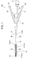
- FIG. 1 is a sectional view taken along line VI-VI of FIG.
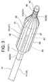
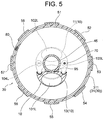
- FIG. 2 is a cross-sectional view taken along the line VII-VII of FIG. It is a partially enlarged view of FIG.
- the balloon-type electrode catheter 100 of this embodiment is a balloon-type electrode catheter for treating lung cancer by high-frequency ablation.
- the balloon-type electrode catheter 100 of the present embodiment shown in FIGS. 1 to 8 includes a catheter tube 10 having main lumens 101L and 102L having an elliptical cross-sectional shape and sublumens 103L and 104L having a circular cross-sectional shape. It has an electrical connector 21 arranged on the proximal end side of the catheter tube 10, an expansion portion 31 that expands and contracts, and neck portions (tip end side neck portion 33 and proximal end side neck portion 35) that are continuous at both ends thereof.
- the base end side neck portion 35 is fixed to the circular tubular portion 11 constituting the tip portion of the catheter tube 10, and the expansion portion 31 includes the semicircular tubular portion 13 constituting the tip portion of the catheter tube 10.
- a balloon 30 connected to the tip side of the tube 10; a tip tip 40 fixed to the tip side neck portion 33 and extending to the outside of the balloon 30, and a tip tip 40 connected to the base end side of the tip tip 40 and connected to the balloon 30.
- a reinforcing shaft 45 made of a PEEK resin tube extending inside the expansion portion 31 along the central axis, and an outer surface of the expansion portion 31 and the tip side neck portion 33 of the balloon 30 are formed, and each tip portion is a tip tip.
- Band-shaped electrodes 51 to 58 (surface electrodes) made of a metal thin film extending to the outer surface of 40; attached to the tip tip 40, and the tips of the band-shaped electrodes 51 to 58 are fixed to the outer peripheral surface thereof.
- a metal ring 60 electrically connected to each of the strip electrodes 51-58; the tip of the metal ring 60 is connected to the inner peripheral surface of the metal ring 60, and the inside of the balloon 30 and the sub of the catheter tube 10 (circular tubular portion 11).
- a lead wire 70 extending to the lumen 103L and having its base end connected to the electrical connector 21; its tip (temperature measuring part 81) is embedded in the tube wall of the expansion part 31 of the balloon 30, and the extension part 31 and the base end are embedded.
- a temperature sensor 80 extending to the tube wall of the side neck portion 35 and the sublumen 104L of the catheter tube 10 (circular tubular portion 11) and having its base end connected to the electrical connector 21. ;
- the catheter tube 10 extends from the proximal end of the expansion portion 31 of the balloon 30 toward the proximal end, and from the proximal end of the expansion portion 31 toward the distal end, and the distal end surface 14 thereof.
- the semicircular tubular portion 13 of the catheter shaft 10 is radially displaced from the central axis of the balloon 30, and the semicircular tubular portion 13 and the reinforcing shaft 45 are adhesively fixed;
- the main lumen 101L of the catheter tube 10 is a fluid supply lumen that circulates the fluid in order to supply the fluid inside the balloon 30, and the main lumen 102L is a lumen 30 that supplies the fluid supplied to the inside of the balloon 30.
- the lumen for discharging the fluid is a lumen for passing the fluid in order to discharge the fluid from the inside
- the sub-lumen 103L is the lumen for inserting the lead wire 70
- the sub-lumen 104L is the lumen for inserting the temperature sensor 80.
- the fluid supply lumen (main lumen 101L) is arranged inside the circular tubular portion 11 and the semicircular tubular portion 13 and opens at the tip surface 14 of the semicircular tubular portion 13 to discharge the fluid (main lumen 102L).
- 20 is a Y connector connected to the proximal end side of the catheter tube 10
- 22 is a fluid supply connector
- 23 is a fluid discharge connector
- 26 is a conductor protection tube
- 27 is a fluid supply tube.
- 28 are fluid discharge tubes.
- the catheter tube 10 constituting the balloon-type electrode catheter 100 is composed of a circular tubular portion 11 and a semicircular tubular portion 13.
- the base end portion and a part of the tip end portion of the catheter tube 10 are formed of a circular tubular portion 11, and the tip end portion (excluding the above part) of the catheter tube 10 is formed of a semicircular tubular portion 13.
- each of the lumens 101L to 104L is formed by a lumen tube surrounding the lumen tube, and these lumen tubes are fixed by a binder resin forming the circular tubular portion 11.
- the cross-sectional shapes of the main lumens 101L and 102L are elliptical, so that two main lumens having a large area can be arranged in the cross section of the circular tubular portion 11.
- the area ratio of each of the main lumens 101L and 102L to the cross section of the circular tubular portion 11 is 20% or more, preferably 25% or more, more preferably 25 to 30%, and 29.3% to give a suitable example. Is.
- the area ratio occupied by the lumen for circulating the fluid is less than 20%, the sufficient cooling effect cannot be exhibited. On the other hand, if this area ratio is excessive, it may not be possible to secure sufficient strength as a catheter tube.
- the guide wire lumen is not formed in the catheter tube 10. This makes it possible to form a main lumen having a large cross-sectional area.
- the main lumen 101L is formed inside the semicircular tubular portion 13 of the catheter tube 10 continuously from the inside of the circular tubular portion 11.
- the lumen tube surrounding the main lumen 101L is fixed by the binder resin forming the semicircular tubular portion 13.
- the main lumen 101L arranged inside the circular tubular portion 11 and the inside of the semicircular tubular portion 13 is open at the distal end surface 14 of the semicircular tubular portion 13 which is the distal end surface of the catheter tube 10.
- the main lumen 101L communicates with the fluid supply connector 22 shown in FIG. 1, whereby the main lumen 101L is a “fluid supply lumen” for supplying fluid to the inside of the balloon 30 (expansion portion 31). ".
- the fluid supplied to the inside of the balloon 30 physiological saline can be exemplified.
- the main lumen 102L, the sub-lumens 103L and 104L formed inside the circular tubular portion 11 are opened at the tip surface 12 of the circular tubular portion 11, respectively.
- the opening of the sub-lumen 103L into which the lead wire 70 is inserted and the opening of the sub-lumen 104L into which the temperature sensor 80 is inserted are sealed with a sealing material, respectively, and the fluid to these sub-lumens 103L and 104L is sealed. The inflow is prevented.
- the main lumen 102L communicates with the fluid discharge connector 23 shown in FIGS. 1 and 2, whereby the main lumen 102L allows the fluid supplied to the inside of the balloon 30 (expansion portion 31) to be transferred to the balloon 30. It becomes a "fluid discharge lumen" for discharging from the inside.
- the constituent material of the catheter tube 10 is not particularly limited, and examples thereof include polyamide resins such as polyamide, polyether polyamide, polyether block amide (PEBAX (registered trademark)) and nylon. Of these, PEBAX is preferable.
- the outer diameter of the catheter tube 10 is usually 1.0 to 3.3 mm, and a suitable example is 1.5 mm.
- the length of the catheter tube 10 is usually 100 to 2200 mm, and a suitable example is 1200 mm.
- the length of the circular tubular portion 11 of the catheter tube 10 is usually 300 to 3000 mm, and a suitable example is 1180 mm.
- the length of the semicircular tubular portion 13 of the catheter tube 10 is usually 5 to 300 mm, and a suitable example is 20 mm.
- a Y connector 20 is connected to the proximal end side of the catheter tube 10.
- the lumen tube surrounding the main lumen 101L (fluid supply lumen) and the main lumen 102L (fluid discharge lumen) of the catheter tube 10 enters the inside of the Y connector 20 from the base end of the catheter tube 10.
- the base end of the lumen tube surrounding the main lumen 101L (fluid supply lumen) is connected to the fluid supply tube 27 inside the Y connector 20.
- the fluid supply tube 27 extends to the outside of the Y connector 20, and the base end of the fluid supply tube 27 is connected to the fluid supply connector 22.
- the base end of the lumen tube surrounding the main lumen 102L (fluid discharge lumen) is connected to the fluid discharge tube 28 inside the Y connector 20.
- the fluid discharge tube 28 extends to the outside of the Y connector 20, and the base end of the fluid discharge tube 28 is connected to the fluid discharge connector 23.
- the balloon 30 constituting the balloon-type electrode catheter 100 includes an expansion portion 31 that expands and contracts, a distal neck portion 33 that is continuous with the tip of the expansion portion 31, and a proximal neck portion 35 that is continuous with the proximal end of the expansion portion 31. It is composed of and.
- the expansion portion 31 of the balloon 30 is a space forming portion that expands when a fluid is supplied to the inside of the balloon 30 and contracts when the fluid is discharged from the inside thereof.
- the expansion portion 31 of the balloon 30 includes a cylindrical portion 311, a distal cone portion 313 from the tip of the cylindrical portion 311 to the proximal end of the distal neck portion 33, and a proximal to proximal neck of the cylindrical portion 311. It is composed of a base end side cone portion 315 reaching the tip of the portion 35.
- the base end side neck portion 35 is fixed to the tip portion of the catheter tube 10 (tip portion composed of the circular tubular portion 11), and the tip portion of the catheter tube 10 (tip portion composed of the semicircular tubular portion 13).
- the balloon 30 is connected to the distal end side of the catheter tube 10 by the expansion portion 31 containing the balloon 30.
- the surface layer portion of the tip portion of the catheter tube 10 (circular tubular portion 11) to which the proximal end side neck portion 35 of the balloon 30 is fixed is scraped, and the outer diameter thereof is the proximal end side neck portion 35. It is smaller than the outer diameter of the base end of the unfixed catheter tube 10. Further, the outer diameter of the proximal end side neck portion 35 is substantially equal to the outer diameter of the proximal end portion of the catheter tube 10 (circular tubular portion 11). As a result, it is possible to prevent the sheath and the endoscope used for introducing the balloon-type electrode catheter 100 from being impaired by the proximal neck portion 35 in terms of insertability into the lumen.
- the tip surface 14 of the semicircular tubular portion 13 through which the main lumen 101L (fluid supply lumen) opens is inside the vicinity of the tip of the cylindrical portion 311 which is on the tip side of the axially intermediate position of the expansion portion 31 of the balloon 30. Is located in.
- the fluid flowing through the main lumen 101L (fluid supply lumen) is discharged from the opening in the tip surface 14 of the semicircular tubular portion 13 toward the tip, and the discharged fluid reaches the vicinity of the tip of the tip side cone portion 313. This makes it possible to form a fluid flow from the distal end side to the proximal end side inside the balloon 30 (expansion portion 31).
- the opening position of the fluid supply lumen is closer to the proximal end side than the axially intermediate position of the expansion portion of the balloon, even if the fluid is discharged from the opening toward the tip end after the balloon is expanded, the expansion portion of the expansion portion The fluid cannot reach the vicinity of the tip, and the flow of the fluid from the tip side to the base end side cannot be formed inside the balloon.
- the tip surface 12 of the circular tubular portion 11 to which the main lumen 102L (fluid discharge lumen) opens is located at the base end of the expansion portion 31 of the balloon 30.
- the constituent material of the balloon 30 is not particularly limited, and the same balloon as that constituting a conventionally known balloon catheter can be used.
- polyamide such as polyamide, polyether polyamide, PEBAX and nylon.
- Polyurethane-based resins such as thermoplastic polyether urethane, polyether polyurethane urea, fluorine polyether urethane urea, polyether polyurethane urea resin, and polyether polyurethane ureaamide can be mentioned.
- the diameter of the balloon 30 (expansion portion 31) is usually 0.70 to 30.0 mm, and a suitable example is 3.5 mm.
- the length of the balloon 30 (expansion portion 31) is usually 8 to 50 mm, and a suitable example is 20 mm.
- the tip tip 40 constituting the balloon type electrode catheter 100 is fixed to the tip side neck portion 33 and extends to the outside of the balloon 30.
- the constituent material of the tip chip 40 is not particularly limited, and examples thereof include polyamides, polyether polyamides, polyamide resins such as PEBAX and nylon, and polyurethanes.
- the inner diameter of the tip tip 40 is usually 0 to 3.0 mm, and a suitable example is 0.8 mm.
- the outer diameter of the tip tip 40 is usually 0.5 to 3.1 mm, and a suitable example is 1.1 mm.
- the outer diameter of the tip side neck portion 33 of the balloon 30 to which the tip tip 40 is fixed is usually 0.6 to 3.2 mm, and a suitable example is 1.2 mm.
- the resin 90 is embedded in the tip portion of the tip tip 40.
- the reinforcing shaft 45 constituting the balloon-type electrode catheter 100 is connected to the proximal end side of the tip tip 40, and the extension portion 31 (tip side cone portion) is connected along the central axis of the balloon 30. 313, extending into the cylindrical portion 311), the base end surface of the reinforcing shaft 45 is located near the base end of the cylindrical portion 311.
- the reinforcing shaft 45 is made of PEEK (polyetheretherketone) tube resin, and the resin 90 is embedded inside the base end portion thereof.
- the highly rigid PEEK resin tube can exert a sufficient reinforcing effect, and the resin 90 can prevent the fluid from leaking from the tip opening of the tip tip 40.
- the outer diameter of the reinforcing shaft 45 is usually 0.4 to 3.0 mm, and a suitable example is 0.7 mm.
- the outer surface of the expansion portion 31 (cylindrical portion 311 and the tip side cone portion 313) of the balloon 30 and the tip side neck portion 33 extends along the axial direction of the balloon 30 as a surface electrode to which a high frequency current is applied.
- the strip-shaped electrodes 51 to 58 formed of the metal thin film are arranged at intervals of 45 ° along the circumferential direction of the balloon 30. Each tip of the band-shaped electrodes 51 to 58 extends beyond the tip of the balloon 30 (tip side neck 33) to the outer surface of the tip tip 40.
- Examples of the constituent material of the metal thin film constituting the strip electrodes 51 to 58 include gold, platinum, silver, copper, alloys thereof, and stainless steel.
- the film thickness of the metal thin film constituting the band-shaped electrodes 51 to 58 is preferably 0.5 to 5 ⁇ m, more preferably 1.0 to 2.5 ⁇ m. If this film thickness is too small, the metal thin film may become hot due to Joule heat during the procedure (during high frequency energization). On the other hand, when the film thickness of the thin film is excessive, it becomes difficult for the metal thin film to follow the shape change of the balloon due to the expansion and contraction, and the expansion and contraction of the balloon may be impaired.
- the method for forming the metal thin film constituting the strip electrodes 51 to 58 on the outer surface of the balloon 30 is not particularly limited, and a normal metal thin film forming method such as thin film deposition, sputtering, plating, or printing may be adopted. can.
- a metal ring 60 is attached to the outer surface of the tip tip 40.
- the tips of the strip electrodes 51 to 58 are fixed to the outer peripheral surface of the metal ring 60.
- each of the band-shaped electrodes 51 to 58 and the metal ring 60 are electrically connected.
- Examples of the constituent material of the metal ring 60 include platinum or a platinum-based alloy.
- the inner diameter of the metal ring 60 is usually 0.5 to 3.1 mm, and a suitable example is 1.1 mm.
- the outer diameter of the metal ring 60 is usually 0.6 to 3.2 mm, and a suitable example is 1.2 mm.
- the tip of the conducting wire 70 is fixed to the inner peripheral surface of the metal ring 60.
- the conductor 70 extends from the Y connector 20 through the inside of the balloon 30, the sublumen 103L of the catheter tube 10 (circular tubular portion 11), the inside of the Y connector 20, and the inside of the conductor protection tube 26.
- the base end of the conducting wire 70 is connected to the electric connector 21.
- the electric connector 21 has a function as an energizing connector for energizing each of the band-shaped electrodes 51 to 58 with a high-frequency current, and a function as a thermocouple connector for connecting the temperature sensor 80 to the temperature measuring device. ..
- each of the band-shaped electrodes 51 to 58 By connecting each of the band-shaped electrodes 51 to 58 to the electric connector 21 via the metal ring 60 and the conducting wire 70, a high-frequency current can be evenly applied to each of the band-shaped electrodes 51 to 58.
- Examples of the constituent material of the lead wire 70 include copper, silver, gold, platinum, tungsten, and alloys of these metals, and it is preferable that an electrically insulating protective coating such as a fluororesin is applied.
- a temperature sensor 80 made of a thermocouple is embedded in the tube wall of the balloon 30.
- the side temperature portion 81 (temperature measurement contact) of the temperature sensor 80 is located on the tube wall of the expansion portion 31.
- the temperature sensor 80 enters the sublumen 104L of the catheter tube 10 (circular tubular portion 11) from the tube wall of the neck portion 35 on the proximal end side of the balloon 30 and extends to the sublumen 104L, inside the Y connector 20. It extends from the Y connector 20 through the inside of the conductor protection tube 26. The base end of the temperature sensor 80 is connected to the electrical connector 21.
- a wide range of high-frequency ablation treatment can be performed on the lesion by each of the band-shaped electrodes 51 to 58 formed on the outer surface of the balloon 30.
- the main lumen 101L (fluid supply lumen) opens at the tip surface 14 of the semicircular tubular portion 13 located inside the vicinity of the tip of the cylindrical portion 311 of the balloon 30, and the main lumen 102L (fluid discharge lumen).
- the opening is made at the tip surface 12 of the circular tubular portion 11 located at the base end of the expansion portion 31 of the balloon 30.
- a fluid flow can be formed from the distal end side to the proximal end side, and the fluid can be made to flow.
- the fluid supply lumen and the fluid discharge lumen are composed of the main lumens 101L and 102L having a large cross-sectional area, respectively, the amount of fluid supplied to the inside of the balloon 30 and the amount of fluid discharged from the inside of the balloon 30 That is, the flow rate of the fluid circulating inside the balloon 30 can be significantly increased as compared with the conventional one. As a result, the inside of the balloon 30 can be efficiently cooled over the entire area of the expansion portion 31, whereby the tissue around the band-shaped electrodes 51 to 58 is sufficiently cooled and the tissue is fibrotic. It can be reliably prevented.
- the metal ring 60 is attached to the outer surface of the tip tip 40, and the tip portions of the band-shaped electrodes 51 to 58 are fixed to the outer peripheral surface of the metal ring 60, so that each of the band-shaped electrodes 51 to 54 can be formed. Since it is electrically connected to the electric connector 21 via the metal ring 60 and the conducting wire 70, a high-frequency current can be evenly applied to each of the band-shaped electrodes 51 to 58, whereby the lesion tissue can be formed.
- the ablation treatment can be uniformly performed along the circumferential direction of the vessel.
- the metal ring 60 since the outer diameter of the metal ring 60 is smaller than the outer diameter of the catheter tube 10 and the neck portion 35 on the proximal end side, the metal ring 60 does not get caught in the opening of the sheath or endoscope used at the time of introduction. , The insertability of the balloon-type electrode catheter 100 into the sheath or the lumen of the endoscope is not impaired.
- Cases to which the balloon-type electrode catheter 100 of the present embodiment can be applied include tumors and vagus nerves in or around the vasculature, and specifically, lung cancer, esophageal cancer, gastric cancer, small intestine cancer, colon cancer and the like. Can be mentioned.
- the present invention is not limited to these embodiments, and various modifications can be made.
- the tip side cone It may be inside the portion 313.
- at least the portion of the band-shaped electrode 51 to 58 located at the tip side cone portion 313 of the balloon 30 is insulated and coated, so that the portion of the band-shaped electrode 51 to 58 located at the cylindrical portion 311 of the balloon 30 is coated.
- the cauterization may be performed only by the corn.
- the entire area of the distal end side cone portion 313 and the distal end side neck portion 33 is insulated. Examples of the covering mode can be mentioned.
- the central angle of the semicircular tubular portion 13 in the cross section is 180 °, it may be a substantially semicircular tubular portion having a central angle of 160 to 200 °, preferably 170 to 190 °.
- the outflow of the fluid to the proximal end side of these sublumens may be prevented by sealing the respective proximal ends with a sealing material.
- Balloon type electrode catheter 10
- Catheter tube 101L Main lumen (lumen for fluid supply) 102L main lumen (lumen for fluid supply) 103L, 104L Sublumen 11
- Circular tubular part 12 Tip surface of circular tubular part 13
- Semi-circular tubular part 14 Tip surface of semi-circular tubular part 20
- Electrical connector 22
- Fluid supply connector 23
- Fluid discharge connector 26
- Conductor protection tube 27
- Fluid supply tube 28
- Balloon 31 Expansion part 311 Cylindrical part 313 Tip side cone part 315 Base end side cone part 33 Tip side neck part 35 Base end side neck part 40 Tip tip 45 Reinforcing shaft 51 to 58 strip Electrode (surface electrode) 60
- Conductor 80
- Temperature sensor thermocouple
- Temperature measuring part of temperature sensor 90
- Resin 10
Landscapes
- Health & Medical Sciences (AREA)
- Surgery (AREA)
- Engineering & Computer Science (AREA)
- Life Sciences & Earth Sciences (AREA)
- Biomedical Technology (AREA)
- Molecular Biology (AREA)
- Nuclear Medicine, Radiotherapy & Molecular Imaging (AREA)
- Plasma & Fusion (AREA)
- Physics & Mathematics (AREA)
- Heart & Thoracic Surgery (AREA)
- Medical Informatics (AREA)
- Otolaryngology (AREA)
- Animal Behavior & Ethology (AREA)
- General Health & Medical Sciences (AREA)
- Public Health (AREA)
- Veterinary Medicine (AREA)
- Surgical Instruments (AREA)
- Media Introduction/Drainage Providing Device (AREA)
Priority Applications (3)
| Application Number | Priority Date | Filing Date | Title |
|---|---|---|---|
| JP2022509858A JP7352728B2 (ja) | 2020-03-24 | 2020-03-24 | バルーン型電極カテーテル |
| PCT/JP2020/013169 WO2021192066A1 (ja) | 2020-03-24 | 2020-03-24 | バルーン型電極カテーテル |
| TW110101772A TWI768661B (zh) | 2020-03-24 | 2021-01-18 | 氣球型電極導管 |
Applications Claiming Priority (1)
| Application Number | Priority Date | Filing Date | Title |
|---|---|---|---|
| PCT/JP2020/013169 WO2021192066A1 (ja) | 2020-03-24 | 2020-03-24 | バルーン型電極カテーテル |
Publications (1)
| Publication Number | Publication Date |
|---|---|
| WO2021192066A1 true WO2021192066A1 (ja) | 2021-09-30 |
Family
ID=77891243
Family Applications (1)
| Application Number | Title | Priority Date | Filing Date |
|---|---|---|---|
| PCT/JP2020/013169 Ceased WO2021192066A1 (ja) | 2020-03-24 | 2020-03-24 | バルーン型電極カテーテル |
Country Status (3)
| Country | Link |
|---|---|
| JP (1) | JP7352728B2 (https=) |
| TW (1) | TWI768661B (https=) |
| WO (1) | WO2021192066A1 (https=) |
Cited By (1)
| Publication number | Priority date | Publication date | Assignee | Title |
|---|---|---|---|---|
| JP2024136977A (ja) * | 2023-03-24 | 2024-10-04 | 日本ライフライン株式会社 | バルーン型アブレーションデバイス |
Citations (3)
| Publication number | Priority date | Publication date | Assignee | Title |
|---|---|---|---|---|
| US20120109118A1 (en) * | 2010-10-29 | 2012-05-03 | Medtronic Ablation Frontiers Llc | Cryogenic-radiofrequency ablation system |
| US20130197499A1 (en) * | 2012-01-27 | 2013-08-01 | Medtronic Cryocath Lp | Balloon design to enhance cooling uniformity |
| WO2020035919A1 (ja) * | 2018-08-15 | 2020-02-20 | 日本ライフライン株式会社 | バルーン型電極カテーテル |
Family Cites Families (4)
| Publication number | Priority date | Publication date | Assignee | Title |
|---|---|---|---|---|
| TWI517833B (zh) | 2009-03-31 | 2016-01-21 | 東麗股份有限公司 | 附有氣球之電燒導管用軸及附有氣球之電燒導管系統 |
| WO2014159276A1 (en) | 2013-03-14 | 2014-10-02 | Recor Medical, Inc. | Ultrasound-based neuromodulation system |
| JP2018509249A (ja) * | 2015-03-25 | 2018-04-05 | リグスホスピタレット コペンハーゲン ユニバーシティ ホスピタル | 持続的な神経ブロックのための先端にバルーンを有するカテーテル |
| JP6265434B2 (ja) | 2015-03-27 | 2018-01-24 | 日本ライフライン株式会社 | バルーン型アブレーションカテーテルおよびアブレーションカテーテル装置 |
-
2020
- 2020-03-24 JP JP2022509858A patent/JP7352728B2/ja active Active
- 2020-03-24 WO PCT/JP2020/013169 patent/WO2021192066A1/ja not_active Ceased
-
2021
- 2021-01-18 TW TW110101772A patent/TWI768661B/zh not_active IP Right Cessation
Patent Citations (3)
| Publication number | Priority date | Publication date | Assignee | Title |
|---|---|---|---|---|
| US20120109118A1 (en) * | 2010-10-29 | 2012-05-03 | Medtronic Ablation Frontiers Llc | Cryogenic-radiofrequency ablation system |
| US20130197499A1 (en) * | 2012-01-27 | 2013-08-01 | Medtronic Cryocath Lp | Balloon design to enhance cooling uniformity |
| WO2020035919A1 (ja) * | 2018-08-15 | 2020-02-20 | 日本ライフライン株式会社 | バルーン型電極カテーテル |
Cited By (1)
| Publication number | Priority date | Publication date | Assignee | Title |
|---|---|---|---|---|
| JP2024136977A (ja) * | 2023-03-24 | 2024-10-04 | 日本ライフライン株式会社 | バルーン型アブレーションデバイス |
Also Published As
| Publication number | Publication date |
|---|---|
| TWI768661B (zh) | 2022-06-21 |
| JP7352728B2 (ja) | 2023-09-28 |
| TW202140095A (zh) | 2021-11-01 |
| JPWO2021192066A1 (https=) | 2021-09-30 |
Similar Documents
| Publication | Publication Date | Title |
|---|---|---|
| JP6968287B2 (ja) | バルーン型電極カテーテル | |
| TWI523635B (zh) | 電位測定用導管 | |
| US6669692B1 (en) | Ablation catheter with cooled linear electrode | |
| CN105050523B (zh) | 开放式灌注消融导管 | |
| JP6308683B2 (ja) | バルーン型アブレーションカテーテル | |
| WO2016158291A1 (ja) | バルーン型アブレーションカテーテルおよびアブレーションカテーテル装置 | |
| JP6894582B2 (ja) | バルーン型電極カテーテル | |
| JP7407843B2 (ja) | バルーン型電極カテーテル | |
| JP7352728B2 (ja) | バルーン型電極カテーテル | |
| JP7385716B2 (ja) | バルーン型カテーテル | |
| JP7579449B2 (ja) | バルーン型電極カテーテル | |
| JP2006198209A (ja) | バルーン付きアブレーションカテーテル | |
| WO2022190225A1 (ja) | バルーン型電極カテーテル |
Legal Events
| Date | Code | Title | Description |
|---|---|---|---|
| 121 | Ep: the epo has been informed by wipo that ep was designated in this application |
Ref document number: 20927556 Country of ref document: EP Kind code of ref document: A1 |
|
| ENP | Entry into the national phase |
Ref document number: 2022509858 Country of ref document: JP Kind code of ref document: A |
|
| NENP | Non-entry into the national phase |
Ref country code: DE |
|
| 122 | Ep: pct application non-entry in european phase |
Ref document number: 20927556 Country of ref document: EP Kind code of ref document: A1 |