WO2021192025A1 - 電動搬送車用充電装置およびそれを備えた物品搬送システム - Google Patents
電動搬送車用充電装置およびそれを備えた物品搬送システム Download PDFInfo
- Publication number
- WO2021192025A1 WO2021192025A1 PCT/JP2020/012989 JP2020012989W WO2021192025A1 WO 2021192025 A1 WO2021192025 A1 WO 2021192025A1 JP 2020012989 W JP2020012989 W JP 2020012989W WO 2021192025 A1 WO2021192025 A1 WO 2021192025A1
- Authority
- WO
- WIPO (PCT)
- Prior art keywords
- coil
- vehicle
- electric
- power transmission
- charging device
- Prior art date
- Legal status (The legal status is an assumption and is not a legal conclusion. Google has not performed a legal analysis and makes no representation as to the accuracy of the status listed.)
- Ceased
Links
Images


Classifications
-
- H—ELECTRICITY
- H02—GENERATION; CONVERSION OR DISTRIBUTION OF ELECTRIC POWER
- H02J—ELECTRIC POWER NETWORKS; CIRCUIT ARRANGEMENTS OR SYSTEMS FOR SUPPLYING OR DISTRIBUTING ELECTRIC POWER; SYSTEMS FOR STORING ELECTRIC ENERGY
- H02J50/00—Circuit arrangements or systems for wireless supply or distribution of electric power
- H02J50/10—Circuit arrangements or systems for wireless supply or distribution of electric power using inductive coupling
-
- H—ELECTRICITY
- H02—GENERATION; CONVERSION OR DISTRIBUTION OF ELECTRIC POWER
- H02J—ELECTRIC POWER NETWORKS; CIRCUIT ARRANGEMENTS OR SYSTEMS FOR SUPPLYING OR DISTRIBUTING ELECTRIC POWER; SYSTEMS FOR STORING ELECTRIC ENERGY
- H02J50/00—Circuit arrangements or systems for wireless supply or distribution of electric power
- H02J50/90—Circuit arrangements or systems for wireless supply or distribution of electric power involving detection or optimisation of position, e.g. alignment
-
- Y—GENERAL TAGGING OF NEW TECHNOLOGICAL DEVELOPMENTS; GENERAL TAGGING OF CROSS-SECTIONAL TECHNOLOGIES SPANNING OVER SEVERAL SECTIONS OF THE IPC; TECHNICAL SUBJECTS COVERED BY FORMER USPC CROSS-REFERENCE ART COLLECTIONS [XRACs] AND DIGESTS
- Y02—TECHNOLOGIES OR APPLICATIONS FOR MITIGATION OR ADAPTATION AGAINST CLIMATE CHANGE
- Y02T—CLIMATE CHANGE MITIGATION TECHNOLOGIES RELATED TO TRANSPORTATION
- Y02T10/00—Road transport of goods or passengers
- Y02T10/60—Other road transportation technologies with climate change mitigation effect
- Y02T10/70—Energy storage systems for electromobility, e.g. batteries
Definitions
- the present invention relates to a charging device for an electric transport vehicle for charging an electric transport vehicle and an article transport system provided with the charging device.
- Charging is performed by bringing the power transmission coil provided in the charging device and the power receiving coil provided in the vehicle close to each other, and then passing an electric current through the power transmission coil.
- In order to automate the charging operation it is necessary to automate the alignment between the power transmission coil and the power reception coil.
- the transport route is often set so that there is no or few reverse movements.
- the power receiving coil is installed at the rear of the vehicle, a reverse operation is required when the vehicle is brought closer to the charging device before charging.
- the power receiving coil is installed in the front part of the vehicle, a reverse operation is required when moving the vehicle away from the charging device after charging.
- the power receiving coil is installed on the side of the vehicle, it is sufficient to move the vehicle forward on the side of the charging device both when the vehicle is brought closer to and away from the charging device. Therefore, in order to improve the efficiency of the transport operation, it is preferable that the power receiving coil is installed on the side of the vehicle.
- Patent Document 1 discloses a charging device that is not a charging device for an electric vehicle, but automatically charges an electric vehicle provided with a power receiving coil on the side.
- This charging device includes a probe having a power transmission coil and three or four gap sensors arranged around the power transmission coil, a motor for moving the probe in the front-rear direction of the vehicle, and a motor for moving the probe in the left-right direction of the vehicle. It is equipped with a motor that moves the probe in the vertical direction of the vehicle.
- the power receiving coil is embedded in a protrusion protruding laterally from the side cover of the vehicle. When charging, the probe is positioned parallel to the protrusion.
- the electric transport vehicle stops on the side of the charging device, it may stop with the vehicle body tilted to the left or right.
- the probe even if the positions of the probe in the vehicle front-rear direction, the vehicle left-right direction, and the vehicle up-down direction are adjusted, the probe is not parallel to the protrusion. Therefore, the power transmission coil does not face the power reception coil, and the charging efficiency may decrease.
- An object of the present invention is to provide a charging device for an electric transport vehicle capable of efficiently charging even when the electric transport vehicle having a power receiving coil on the side is stopped in a state of being tilted to the left or right. It is to provide a transport system.
- the charging device for an electric transport vehicle disclosed here is a charging device for an electric transport vehicle that charges from the side of the electric transport vehicle.
- the charging device for an electric transport vehicle is movable on a base member installed on the floor and in a first direction with respect to the base member and a second direction opposite to the first direction, and is attached to the base member.
- a movable member that can rotate around a vertical line, a first actuator that drives the movable member in the first direction and the second direction, and the first actuator that is supported by the movable member and is supported by the movable member.
- It has a coil support member that can move in a direction and the second direction, a transmission coil supported by the coil support member, and a first contact portion located in the first direction with respect to the transmission coil.
- the first contact member provided on the coil support member and the third direction located in the first direction with respect to the power transmission coil and orthogonal to the first direction and the vertical direction from the first contact portion.
- a second contact member having a separated second contact portion and provided on the coil support member, an elastic body for urging the coil support member in the first direction, and the power transmission coil with respect to the movable member. It includes a first sensor that detects a position in the first direction, and a control device that receives a signal from the first sensor and controls the first actuator.
- the first direction is a direction from the charging device for the electric vehicle toward the electric vehicle when the electric vehicle is stopped on the side of the charging device for the electric vehicle.
- the charging device for the electric transport vehicle when the first actuator drives the movable member in the first direction, the power transmission coil moves in the first direction and approaches the power receiving coil of the electric transport vehicle. After the first contact member and the second contact member come into contact with the side portion of the electric transport vehicle, the movable member can move in the first direction, but the movement of the coil support member in the first direction is restricted. Therefore, the position of the power transmission coil with respect to the movable member in the first direction changes, and this position change is detected by the first sensor. Based on the detection result of the first sensor, it is detected that the power transmission coil approaches the power reception coil. That is, it is automatically detected that the position of the power transmission coil and the power reception coil in the first direction are aligned.
- the coil support member supported by the movable member can rotate around the vertical line.
- the coil support member is on the side of the electric transport vehicle. Tilt to the left and right following the part. Therefore, the direction of the power transmission coil is changed, and the power transmission coil automatically faces the power reception coil.
- the alignment of the power transmission coil and the power reception coil in the first direction is automatically performed even when the electric transport vehicle is stopped in a state of being tilted to the left or right.
- the directions of the power transmission coil and the power reception coil are automatically aligned, so that efficient charging is performed.
- the control device drives the first actuator to start the movement of the movable member in the first direction, and the position of the power transmission coil and the movable member in the first direction.
- the first determination unit determines that the difference is equal to or less than the first threshold value. It may have a first movement end portion which ends the movement of the movable member in the first direction by stopping the first actuator.
- the movable member may be configured to be movable with respect to the base member in the third direction and a fourth direction opposite to the third direction.
- the charging device for an electric transport vehicle drives a second sensor that detects the position of the power transmission coil with respect to the power receiving coil of the electric transport vehicle in the third direction, and the movable member in the third direction and the fourth direction.
- the second actuator may be provided.
- the control device may be configured to receive a signal from the second sensor and control the second actuator.
- the alignment of the power transmission coil and the power reception coil in the third direction can be automatically performed.
- the control device includes an actuator control unit that controls the second actuator so that the difference in position between the power transmission coil and the power reception coil in the third direction becomes small, and the first of the power transmission coil and the power reception coil.
- the second determination unit that determines whether or not the difference in position in the three directions is equal to or less than a predetermined second threshold value and the second determination unit determine that the difference in position in the third direction is equal to or less than the second threshold value.
- the movable member may have a second movement end portion that ends the movement of the movable member in the third direction or the fourth direction by stopping the drive of the second actuator.
- the first contact portion of the first contact member and the second contact portion of the second contact member may be formed of a rotatable rotating body.
- the coil support member can be easily moved in the third direction or the fourth direction while the first contact member and the second contact member are in contact with the side portion of the electric transport vehicle. Therefore, the positions of the power transmission coil and the power reception coil in the third direction can be easily adjusted while the first contact member and the second contact member are in contact with the side portion of the electric transport vehicle. Further, when the coil support member is moved in the third direction or the fourth direction, the first contact member and the second contact member do not rub against the side portion of the electric transport vehicle, so that a mark is left on the side portion of the electric transport vehicle. Is hard to stick.
- the first contact member may have a first extension member that is arranged above or below the power transmission coil and extends in the first direction from the coil support member.
- the second contact member may have a second extension member that is arranged above or below the power transmission coil and extends in the first direction from the coil support member.
- the first contact portion may be provided at the tip of the first stretching member, and the second contact portion may be provided at the tip of the second stretching member.
- the first contact member and the second contact member do not get in the way when the power transmission coil is brought close to the power reception coil. Further, when the coil support member is moved in the third direction or the fourth direction while the first contact member and the second contact member are in contact with the side portion of the electric transport vehicle, the first contact member and the second contact member are contacted. It is possible to prevent the member from interfering with the power receiving coil.
- the movable member has a moving member that can move in the first direction and the second direction with respect to the base member, and a rotating member that is rotatably supported by the moving member in a vertical direction. May be good.
- the coil support member may be movably supported by the rotating member in the first direction and the second direction.
- the first sensor may be configured to detect the position of the power transmission coil with respect to the rotating member.
- the elastic body may be a compression spring arranged between the rotating member and the coil supporting member.
- the movable member may have other moving members movably supported in the third direction and the fourth direction by the base member.
- the moving member may be movably supported by the other moving member in the first direction and the second direction.
- the article transport system disclosed here includes the charging device for the electric transport vehicle and one or more electric transport vehicles.
- the electric transport vehicle includes a vehicle body, a power receiving coil arranged on a side portion of the vehicle body, a battery connected to the power receiving coil, an electric motor connected to the battery, and wheels driven by the electric motor. And have.
- the power transmission coil of the electric transport vehicle charging device and the power receiving coil of the electric transport vehicle Alignment can be performed quickly and accurately. Since the charging work of the electric transport vehicle can be performed quickly and efficiently, the efficiency of the goods transporting operation can be improved.
- the electric transport vehicle may be an autonomous vehicle.
- the efficiency of the goods transportation business can be further improved.
- the charging device for the electric transport vehicle may include a vehicle position sensor that detects the position of the electric transport vehicle in the third direction.
- the electric transport vehicle may include a control device that controls the electric motor so as to move the vehicle body forward or backward based on the detection result of the vehicle position sensor.
- the electric transport vehicle automatically stops on the side of the charging device for the electric transport vehicle prior to charging. Therefore, the efficiency of the article transportation operation can be further improved.
- the electric carrier includes a vehicle body, a power receiving coil, a battery, an electric motor, a towing vehicle having the wheels, a loading platform and wheels on which articles are placed, and one or two or more connected to the towing vehicle. Towed vehicles and may be included.
- the electric transport vehicle may be configured to travel both indoors and outdoors.
- the electric transport vehicle does not have to be equipped with a device for detecting a guide wire buried in the ground.
- the electric transport vehicle may be a vehicle that autonomously travels.
- a charging device for an electric transport vehicle capable of efficiently charging even when the electric transport vehicle having a power receiving coil on the side is stopped in a state of being tilted to the left or right, and a charging device for the electric transport vehicle.
- a transport system can be provided.
- the article transport system 100 is a system for transporting articles by an electric transport vehicle 10 in the factory site 1.
- the article transport system 100 includes one or more electric transport vehicles 10 capable of loading and traveling articles, an electric transport vehicle charging device (hereinafter, simply referred to as a charging device) 20 for charging the electric transport vehicle 10. It is equipped with a command computer 30 that gives commands to the electric transport vehicle 10 and the charging device 20.
- the charging device 20 is installed inside the building 2.
- the installation location of the charging device 20 is not limited at all.
- the charging device 20 may be installed inside other buildings 3 to 5. Further, the charging device 20 may be installed outside the buildings 2 to 5. That is, the charging device 20 may be installed indoors or outdoors.
- the command computer 30 is installed inside the building 2.
- the installation location of the command computer 30 is not limited at all.
- the command computer 30 may be installed inside other buildings 2 to 5. Further, the command computer 30 may be installed at a place other than the factory site 1.
- the command computer 30 can communicate with the electric transport vehicle 10 and the charging device 20.
- the command computer 30 may be able to communicate with the electric carrier 10 and the charging device 20 via the Internet.
- the command computer 30 may be composed of one computer or a plurality of computers.
- the electric transport vehicle 10 receives a command from the command computer 30 and travels to the destination through a predetermined movement path 8.
- the electric transport vehicle 10 is a transport vehicle that travels by being driven by an electric motor.
- the electric transport vehicle 10 may be composed of a single vehicle, but in the present embodiment, it is composed of a plurality of vehicles.
- the electric transport vehicle 10 according to the present embodiment is composed of a towing vehicle 11 and two towed vehicles 12 towed by the towing vehicle 11.
- the towing vehicle 11 may have a loading platform on which the article 9 is loaded, but in the present embodiment, the towing vehicle 11 is not provided with a loading platform.
- the article 9 is loaded on the towed vehicle 12.
- the towing vehicle 11 was connected to the vehicle body 11A, the computer 11E mounted on the vehicle body 11A, the power receiving coil 11C arranged on the side of the vehicle body 11A, the battery 11B connected to the power receiving coil 11C, and the battery 11B. It includes an electric motor 11M and wheels 11W connected to the electric motor 11M. The wheels 11W are driven by an electric motor 11M.
- the power receiving coil 11C includes a rectangular parallelepiped protective case and a coil body housed inside the protective case.
- the towing vehicle 11 may be a vehicle driven by a person, but in the present embodiment, it is an automatic driving vehicle. That is, the towing vehicle 11 is a vehicle that can automatically travel without being driven by a person. Further, the towing vehicle 11 according to the present embodiment is a vehicle that autonomously travels.
- autonomous driving means to grasp the external environment based on the information obtained from the detection equipment (GPS sensor, camera, etc.) installed in the vehicle without using the guide line buried in the ground, and to detect obstacles. It means to drive toward the destination while avoiding it.
- the towing vehicle 11 according to the present embodiment is provided with a detection device (not shown), and is configured to autonomously travel under the control of the computer 11E toward the destination instructed by the command computer 30.
- the towed vehicle 12 includes a loading platform 12A on which the article 9 is placed and wheels 12W.
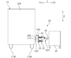
- FIG. 3 is a plan view showing the configurations of the charging device 20 and the towing vehicle 11.
- FIG. 4 is a rear view showing the configuration of the charging device 20 and the towing vehicle 11.
- the reference numeral X in the figure represents the vehicle front-rear direction.
- the reference numeral X1 represents the front and the reference numeral X2 represents the rear.
- the symbol Y represents the vehicle left-right direction.
- the reference numeral Y1 represents the left side, and the reference numeral Y2 represents the right side.
- the symbol Z represents the vehicle vertical direction.
- the symbols Y1, Y2, X1 and X2 are referred to as a first direction, a second direction, a third direction and a fourth direction, respectively.
- the charging device 20 is a device that charges from the side of the towing vehicle 11. At the time of charging, the towing vehicle 11 stops on the side of the charging device 20.
- the charging device 20 includes a base member 25 installed on the floor and a movable member 21K.
- the movable member 21K is movably supported by the base member 25 in the third direction X1 and the fourth direction X2, and is movably supported by the moving member 24 in the first direction Y1 and the second direction Y2. It has a moving member 21 and a rotating member 22 rotatably supported by the moving member 21 in a vertical direction.
- the movable member 21K can move in the first direction Y1 and the second direction Y2 with respect to the base member 25. Further, the movable member 21K can move in the third direction X1 and the fourth direction X2 with respect to the base member 25. Further, the movable member 21K is rotatable around a vertical line with respect to the base member 25.
- the charging device 20 uses the first actuator 21A for driving the moving member 21 in the first direction Y1 and the second direction Y2, and the moving member 24 in the third directions X1 and fourth. It includes a second actuator 24A that drives in direction X2 (see FIG. 6).
- the first actuator 21A and the second actuator 24A are not particularly limited, but are composed of, for example, a servomotor.
- Reflectors 14 are provided in front of and behind the power receiving coil 11C of the towing vehicle 11.
- a vehicle position sensor 29 composed of a reflective photoelectric sensor is provided in front of and behind the power transmission coil 20C of the charging device 20.
- the charging device 20 includes a coil support member 23 movably supported by the rotating member 22 in the first direction Y1 and the second direction Y2, and a power transmission coil 20C supported by the coil support member 23. It has.
- the power transmission coil 20C includes a rectangular parallelepiped protective case and a coil body housed inside the protective case.
- the moving member 21 has a first portion 21a slidable on the moving member 24 and a second portion 21b fixed to the first portion 21a.
- a hole 21h extending in the vertical direction is formed in the second portion 21b.
- the rotating member 22 includes a horizontal plate 22a, a vertical plate 22b extending upward from the left portion of the horizontal plate 22a, a rod-shaped portion 22c extending to the right from the horizontal plate 22a, and a shaft 22d extending upward from the right portion of the rod-shaped portion 22c. And have.
- the shaft 22d is rotatably inserted into the hole 21h of the moving member 21.
- a hole 22h is formed in the vertical plate 22b.
- a spring 27a and a spring 27b are provided between the moving member 21 and the rotating member 22.
- the spring 27a is arranged in front of the shaft 22d, and the spring 27b is arranged behind the shaft 22d.
- the right end of the spring 27a and the right end of the spring 27b are attached to the moving member 21.
- the left end of the spring 27a and the left end of the spring 27b are attached to the rotating member 22.
- the spring 27a pushes the rotating member 22 to the left, and applies a force in the counterclockwise direction to the rotating member 22 in the direction of the shaft 22d.
- the spring 27b pushes the rotating member 22 to the left, and applies a force in the clockwise direction to the rotating member 22 in the direction of the shaft 22d. As shown in FIG.
- the position where the rotating member 22 is not tilted is defined as the neutral position.
- the force of the spring 27a and the force of the spring 27b are balanced.
- the spring 27a and the spring 27b generate a force that returns the rotating member 22 to the neutral position when the rotating member 22 rotates in a vertical direction.
- the coil support member 23 has a vertical plate 23c that supports the power transmission coil 20C, and a rod 23a that extends to the right from the vertical plate 23c.
- the rod 23a is slidably inserted into the hole 22h of the vertical plate 22b of the rotating member 22.
- a spring 28 is arranged between the vertical plate 22b and the vertical plate 23c.
- the spring 28 is a coil spring.
- the rod 23a is arranged inside the spring 28.
- the spring 28 is a compression spring and pushes the vertical plate 23c in the first direction Y1. Since the rod 23a is slidable in the hole 22h of the vertical plate 22b, the coil support member 23 can move in the first direction Y1 and the second direction Y2 with respect to the rotating member 22.
- the power transmission coil 20C is arranged on the left side of the vertical plate 23c. As the coil support member 23 moves in the first direction Y1, the power transmission coil 20C approaches the power reception coil 11C.
- the coil support member 23 is provided with a first contact member 41 and a second contact member 42 extending to the left.
- the first contact member 41 is arranged behind the shaft 22d, and the second contact member 42 is arranged in front of the shaft 22d.
- the first contact member 41 and the second contact member 42 are arranged above the power transmission coil 20C.
- the first contact member 41 has a rod-shaped or plate-shaped stretching member 41a extending to the left from the vertical plate 23c, and a first roller 41b provided at the tip of the stretching member 41a.
- the second contact member 42 has a rod-shaped or plate-shaped extending member 42a extending to the left from the vertical plate 23c, and a second roller 42b provided at the tip of the extending member 42a.
- the first roller 41b and the second roller 42b are portions that come into contact with the side portion 11S of the towing vehicle 11 during charging, and are examples of the first contact portion and the second contact portion, respectively.
- the first roller 41b and the second roller 42b are rotatable and are examples of rotating bodies.
- the first roller 41b and the second roller 42b are arranged to the left of the power transmission coil 20C.
- the charging device 20 includes a first sensor 51 that detects the position of the coil support member 23 with respect to the rotating member 22. Since the power transmission coil 20C is fixed to the coil support member 23, the position of the power transmission coil 20C in the first direction Y1 with respect to the rotating member 22 is detected by the first sensor 51. In the present embodiment, the first sensor 51 indirectly detects the position of the power transmission coil 20C by detecting the position of the coil support member 23. However, the first sensor 51 may be configured to directly detect the position of the power transmission coil 20C. In the present embodiment, the first sensor 51 includes a sensor 51A that detects whether or not the coil support member 23 is in the initial position, and a sensor that detects whether or not the coil support member 23 is in a predetermined limit position. It has 51B.
- the initial position is the position of the coil support member 23 before the first contact member 41 and the second contact member 42 come into contact with the towing vehicle 11.
- the sensor 51A is switched from ON to OFF or from OFF to ON, it is detected that the first contact member 41 and the second contact member 42 are in contact with the side portion 11S of the towing vehicle 11.
- the types of the sensor 51A and the sensor 51B are not particularly limited. In the present embodiment, the sensor 51A and the sensor 51B are composed of a photoelectric sensor that detects the vertical plate 23C.
- the charging device 20 includes a second sensor 52 that detects the position of the power transmission coil 20C in the third direction X1 with respect to the power receiving coil 11C.
- the second sensor 52 is composed of an infrared light emitting element 52B and a light receiving element 52A.
- the light receiving element 52A is provided on the vertical plate 23c.
- the light emitting element 52B is provided on the side portion 11S of the towing vehicle 11.
- the second sensor 52 is not limited to the infrared sensor. As the second sensor 52, various known sensors can be preferably used.
- the charging device 20 moves the moving member 21 in the first direction Y1 and the second direction Y2, and the moving member 24 in the third direction X1 and the fourth direction X2. It includes a second actuator 24A. It also includes a charging device 20 and a controller 60 including a computer. The controller 60 is communicably connected to the first sensor 51, the second sensor 52, the vehicle position sensor 29, the first actuator 21A, and the second actuator 24A. Further, the charging device 20 includes a switch (not shown) for connecting a power source (not shown) and the power transmission coil 20C. The controller 60 is connected to the power transmission coil 20C via the switch, and controls the energization of the power transmission coil 20C.
- the controller 60 includes a CPU, a ROM, a RAM, and the like.
- the controller 60 executes various controls by the CPU reading a program stored in a ROM or the like.
- the controller 60 aligns the power transmission coil 20C and the power reception coil 11C by controlling the first actuator 21A and the second actuator 24A. Further, the controller 60 controls the energization of the power transmission coil 20C by controlling the switch.
- the controller 60 has the first movement start unit 61S, the first determination unit 61D, the first movement end unit 61E, the actuator control unit 62A, and the second determination unit 62D. , And functions as the second movement end unit 62E.
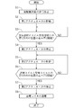
- the electric transport vehicle 10 advances toward the side of the charging device 20.
- the towing vehicle 11 of the electric transport vehicle 10 reaches the side of the charging device 20 (see FIG. 3)
- the light emitted from the vehicle position sensor 29 of the charging device 20 is reflected by the reflector 14 of the towing vehicle 11. It is incident on the vehicle position sensor 29.
- the vehicle position sensor 29 detects that the towing vehicle 11 has arrived at the side of the charging device 20.
- the controller 60 Upon receiving the signal from the vehicle position sensor 29, the controller 60 transmits a signal to the command computer 30 (see FIG. 1) notifying that the towing vehicle 11 has arrived at the side of the charging device 20.
- the command computer 30 transmits a signal instructing the controller 11E of the towing vehicle 11 to stop.
- the controller 11E stops the traveling of the towing vehicle 11. In this way, when the electric transport vehicle 10 arrives at the side of the charging device 20, the electric transport vehicle 10 stops traveling (step S1).
- the towing vehicle 11 stops straight so that the power receiving coil 11C is parallel to the power transmission coil 20C.
- the towing vehicle 11 may stop in a posture tilted to the left or right. In the following description, as shown in FIG. 8, it is assumed that the towing vehicle 11 has stopped in a posture of leaning to the left. In this case, the power transmission coil 20C is non-parallel to the power reception coil 11C.
- the controller 60 drives the first actuator 21A (step S2). As a result, the moving member 21 starts moving in the first direction Y1.
- the start of movement of the moving member 21 in the first direction Y1 is synonymous with the start of movement of the movable member 21K in the first direction Y1.
- the CPU of the controller 60 becomes the first movement start unit 61S.
- the moving member 21 moves in the first direction Y1
- at least one of the first contact member 41 and the second contact member 42 comes into contact with the side portion 11S of the towing vehicle 11.
- the first contact member 41 comes into contact with the side portion 11S of the towing vehicle 11 before the second contact member 42.
- the second contact member 42 comes into contact with the side portion 11S of the towing vehicle 11 before the first contact member 41.
- the rotating member 22 can rotate in a vertical line with respect to the moving member 21.
- the rotating member 22 rotates until the second contact member 42 comes into contact with the side portion 11S of the towing vehicle 11. Then, when the second contact member 42 comes into contact with the side portion 11S of the towing vehicle 11, the rotation of the rotating member 22 is stopped.
- the power transmission coil 20C becomes parallel to the power reception coil 11C.
- the power transmission coil 20C faces the power reception coil 11C.
- the moving member 21 When the first contact member 41 and the second contact member 42 come into contact with the side portion 11S of the towing vehicle 11, the movement of the coil support member 23 in the first direction Y1 is restricted.
- the rotating member 22 can move in the X direction with respect to the coil supporting member 23.
- the position of the coil support member 23 with respect to the rotating member 22 (hereinafter, simply referred to as the position of the coil support member 23) changes. Specifically, as the moving member 21 moves in the first direction Y1, the position of the coil supporting member 23 becomes closer to the rotating member 22.
- the sensor 51A switches from ON to OFF or from OFF to ON.
- the controller 60 receives the signal from the sensor 51A and detects that the first contact member 41 and the second contact member 42 have come into contact with the side portion 11S of the towing vehicle 11.
- the power transmission coil 20C supplies power in a non-contact manner with the power receiving coil 11C.
- the distance between the power transmission coil 20C and the power reception coil 11C in the first direction Y1 is maintained at a distance suitable for charging. Is done. As shown in FIG.
- the sensor 51B switches from ON to OFF or from OFF to ON.
- the controller 60 determines whether or not the difference between the positions of the rotating member 22 and the coil support member 23 in the first direction Y1 is equal to or less than the first threshold value (step S3).
- the first threshold value is stored in the storage unit 63 of the controller 60.
- the controller 60 stops the first actuator 21A (step S4). As a result, the coil support member 23 is pressed against the side portion 11S of the towing vehicle 11 with an appropriate force.
- the CPU of the controller 60 determines whether or not the difference between the positions of the rotating member 22 and the coil support member 23 in the first direction Y1 is equal to or less than the first threshold value based on the detection result of the sensor 51B. 1
- the determination unit 61D Further, the CPU of the controller 60 becomes a first movement end unit 61E that ends the movement of the moving member 21 in the first direction Y1 when the first actuator 21A is stopped.
- determining whether or not the difference between the positions of the rotating member 22 and the coil support member 23 in the first direction Y1 is equal to or less than the first threshold value is the position of the position of the transmission coil 20C and the movable member 21K in the first direction Y1. It is synonymous with determining whether or not the difference is equal to or less than the first threshold value. Ending the movement of the moving member 21 in the first direction Y1 is synonymous with ending the movement of the movable member 21K in the first direction Y1.
- the controller 60 aligns the power transmission coil 20C and the power reception coil 11C in the third direction X1. That is, the controller 60 drives the second actuator 24A so that the difference between the positions of the power transmission coil 20C and the power receiving coil 11C in the third direction X1 becomes small, so that the coil support member 23 is moved to the third direction X1 or the third direction X1 or the third direction X1. It is moved in four directions X2 (step S5). That is, the second actuator 24A is controlled so that the difference in position between the power transmission coil 20C and the power reception coil 11C in the third direction X1 becomes small. At this time, the CPU of the controller 60 becomes the actuator control unit 62A.
- the controller 60 determines whether or not the difference between the positions of the power transmission coil 20C and the power reception coil 11C in the third direction X1 is equal to or less than the second threshold value based on the signal from the second sensor 52 (step S6).
- the second threshold value is a predetermined value and is stored in the storage unit 63 of the controller 60.
- the CPU of the controller 60 becomes the second determination unit 62D when executing the process of step S6.
- step S6 determines whether the determination result in step S6 is NO, the process returns to step S5. If the determination result in step S6 is YES, the controller 60 stops the second actuator 24A (step S7). As a result, the misalignment of the power transmission coil 20C and the power reception coil 11C in the third direction X1 is eliminated.
- the controller 60 supplies a current to the power transmission coil 20C in a state where the first direction Y1 and the third direction X1 of the power transmission coil 20C and the power reception coil 11C are aligned in this way (step S8). That is, the power transmission coil 20C is energized. As a result, the electric transport vehicle 10 is charged.
- electric vehicles as passenger cars are mainly intended to run on public roads, and aesthetics are emphasized. If a part of the charging device 20 (that is, the first contact member 41 and the second contact member 42) comes into contact with the side cover during charging, the side cover may be marked. Therefore, when charging an electric vehicle as a passenger car, it is preferable to use a non-contact type sensor such as a gap sensor in order to surely prevent a mark from being left on the side cover.
- the electric transport vehicle 10 is a vehicle used in factories and the like for the purpose of transporting articles. The aesthetics of the electric transport vehicle 10 are not as important as those of the electric vehicle. Therefore, even if a part of the charging device 20 comes into contact with the side portion 11S during charging, there is no particular problem.
- the charging device 20 according to the present embodiment is based on the characteristics of such an electric transport vehicle 10.
- the charging device 20 when the first actuator 21A drives the moving member 21 in the first direction Y1, the power transmission coil 20C moves in the first direction Y1 and the electric transport vehicle 10 Approaches the power receiving coil 11C of.
- the rotating member 22 After the first contact member 41 and the second contact member 42 come into contact with the side portion (hereinafter referred to as the side portion of the electric transport vehicle 10) 11S of the towing vehicle 11, the rotating member 22 can move in the first direction Y1.
- the movement of the coil support member 23 in the first direction Y1 is restricted. Therefore, the position of the coil support member 23 in the first direction Y1 with respect to the rotating member 22 changes. This position change is detected by the first sensor 51.
- the power transmission coil 20C approaches the power reception coil 11C. That is, it is automatically detected that the positions of the power transmission coil 20C and the power reception coil 11C in the first direction Y1 are aligned.
- the rotating member 22 can rotate in a vertical line with respect to the moving member 21. Therefore, the coil support member 23 supported by the rotating member 22 can rotate around a vertical line.
- the electric transport vehicle 10 is stopped in a state of being tilted to the left and right, after either one of the first contact member 41 and the second contact member 42 comes into contact with the side portion 11S of the electric transport vehicle 10, the coil support member 23 Tilts to the left and right following the side portion 11S of the electric transport vehicle 10. Therefore, the direction of the power transmission coil 20C changes, and the power transmission coil 20C automatically faces the power reception coil 11C.
- the charging device 20 even when the electric transport vehicle 10 is stopped in a state of being tilted to the left or right, the position of the power transmission coil 20C and the power reception coil 11C in the first direction Y1.
- the alignment is automatically performed, and the directions of the power transmission coil 20C and the power reception coil 11C are automatically aligned, so that efficient charging is performed.
- the position of the power transmission coil 20C in the third direction X1 is adjusted by controlling the second actuator 24A based on the signal from the second sensor 52. Therefore, the alignment of the power transmission coil 20C and the power reception coil 11C in the third direction X1 is automatically performed.
- the first contact member 41 and the second contact member 42 When aligning the positions of the power transmission coil 20C and the power reception coil 11C in the third direction X1, the first contact member 41 and the second contact member 42 remain in contact with the side portion 11S of the electric transport vehicle 10 in the third direction X1 or the fourth direction. Move in direction X2.
- the contact portion of the first contact member 41 is composed of the first roller 41b
- the contact portion of the second contact member 42 is composed of the second roller 42b. Therefore, the first contact member 41 and the second contact member 42 smoothly move in the third direction X1 and the fourth direction X2. Therefore, the alignment of the power transmission coil 20C and the power reception coil 11C in the third direction X1 can be easily performed.
- first roller 41b and the second roller 42b are not particularly limited, but the first roller 41b and the second roller 42b are made of rubber so that the side portion 11S of the electric transport vehicle 10 is less likely to be marked. May be good.
- the first contact member 41 and the second contact member 42 are arranged above the power transmission coil 20C. Therefore, when the power transmission coil 20C is brought close to the power reception coil 11C, the first contact member 41 and the second contact member 42 do not get in the way. Further, when the first contact member 41 and the second contact member 42 are moved in the third direction X1 or the fourth direction X2 while being in contact with the side portion 11S of the electric transport vehicle 10, the first contact member 41 and It is possible to prevent the second contact member 42 from interfering with the power receiving coil 11C.
- the first contact member 41 and the second contact member 42 may be arranged below the power transmission coil 20C. In this case as well, the same effect can be obtained.
- the charging operation of the electric transport vehicle 10 can be performed quickly and efficiently as described above, so that the efficiency of the article transport operation can be improved.
- the electric transport vehicle 10 is an autonomous driving vehicle, it is possible to further improve the efficiency of the article transport business. Further, the electric transport vehicle 10 automatically stops on the side of the charging device 20 based on the detection result of the vehicle position sensor 29 prior to charging. Therefore, the efficiency of the article transportation operation can be further improved.
- the movable member 21K moves to the moving member 24 movably supported by the base member 25 in the third direction X1 and the fourth direction X2, and moves to the moving member 24 in the first direction Y1 and the second direction Y2. It has a moving member 21 that is rotatably supported, and a rotating member 22 that is rotatably supported by the moving member 21 in a vertical direction.
- the movable member 21K can move in the first direction Y1 and the second direction Y2, can move in the third direction X1 and the fourth direction X2, and can rotate around the vertical line with respect to the base member 25.
- the configuration is not particularly limited.
- the movable member 21K includes a moving member movably supported by the base member 25 in the third direction X1 and the fourth direction X2, a rotating member rotatably supported by the moving member in a vertical direction, and the like.
- the rotating member may have other moving members movably supported in the first direction Y1 and the second direction Y2.
- the movable member 21K is movably supported by the base member 25 in the first direction Y1 and the second direction Y2, and is movably supported by the moving member in the third direction X1 and the fourth direction X2. It may also have another moving member and a coil supporting member rotatably supported by the other moving member in a vertical direction.
- steps S2 to S4 may be performed after steps S5 to S7.
- steps S2 to S4 and a part or all of steps S5 to S7 may be performed at the same time.
- the first sensor 51 is not particularly limited as long as it can detect the position of the power transmission coil 20C in the first direction Y1 with respect to the movable member 21K.
- the first sensor 51 may be a contact type sensor or a non-contact type sensor.
- the first sensor 51 may be a magnetic sensor or an optical sensor.
- the second sensor 52 is not limited to the infrared sensor.
- the second sensor 52 may be another optical sensor or a magnetic sensor.
- the second sensor 52 is not limited to the non-contact type sensor, and may be a contact type sensor.
- the vehicle position sensor 29 is not limited to the reflection type optical sensor.
- the vehicle position sensor 29 may be another optical sensor or a magnetic sensor.
- the vehicle position sensor 29 is not limited to the non-contact type sensor, and may be a contact type sensor.
- the elastic body that urges the coil support member 23 in the first direction Y1 is not limited to the compression spring that pushes the coil support member 23 in the first direction Y1.
- the elastic body may be a tension spring that pulls the coil support member 23 in the first direction Y1.
- the elastic body is not limited to the coil spring, and may be a spring of another form.
- the elastic body may be an air spring having a cylinder and a rod.
- the rotating body constituting the first contact portion 41b and the second contact portion 42b is not limited to the roller.
- the rotating body may be a ball that can rotate at least vertically.
- the electric transport vehicle 10 is not limited to an autonomous driving vehicle capable of autonomous driving.
- the electric transport vehicle 10 may be an autonomous driving vehicle having a device for detecting a guide line and automatically traveling along the guide line buried in the ground. Further, the electric transport vehicle 10 is not limited to the self-driving vehicle.
- the electric transport vehicle 10 may be a vehicle driven by a person.
- the electric transport vehicle 10 may be a vehicle that travels only outdoors, or may be a vehicle that travels only indoors.
- the place where the goods transportation system 100 is installed is not limited to the factory site 1.
- the article transport system 100 can be applied to any place where the electric transport vehicle 10 is used.
- the goods transport system 100 may be installed in a distribution center, a shopping mall, or the like.
Landscapes
- Engineering & Computer Science (AREA)
- Computer Networks & Wireless Communication (AREA)
- Power Engineering (AREA)
- Charge And Discharge Circuits For Batteries Or The Like (AREA)
- Electric Propulsion And Braking For Vehicles (AREA)
Priority Applications (2)
| Application Number | Priority Date | Filing Date | Title |
|---|---|---|---|
| PCT/JP2020/012989 WO2021192025A1 (ja) | 2020-03-24 | 2020-03-24 | 電動搬送車用充電装置およびそれを備えた物品搬送システム |
| JP2022509823A JP7169487B2 (ja) | 2020-03-24 | 2020-03-24 | 電動搬送車用充電装置およびそれを備えた物品搬送システム |
Applications Claiming Priority (1)
| Application Number | Priority Date | Filing Date | Title |
|---|---|---|---|
| PCT/JP2020/012989 WO2021192025A1 (ja) | 2020-03-24 | 2020-03-24 | 電動搬送車用充電装置およびそれを備えた物品搬送システム |
Publications (1)
| Publication Number | Publication Date |
|---|---|
| WO2021192025A1 true WO2021192025A1 (ja) | 2021-09-30 |
Family
ID=77891205
Family Applications (1)
| Application Number | Title | Priority Date | Filing Date |
|---|---|---|---|
| PCT/JP2020/012989 Ceased WO2021192025A1 (ja) | 2020-03-24 | 2020-03-24 | 電動搬送車用充電装置およびそれを備えた物品搬送システム |
Country Status (2)
| Country | Link |
|---|---|
| JP (1) | JP7169487B2 (https=) |
| WO (1) | WO2021192025A1 (https=) |
Cited By (1)
| Publication number | Priority date | Publication date | Assignee | Title |
|---|---|---|---|---|
| JP2023159626A (ja) * | 2022-04-20 | 2023-11-01 | 株式会社ササキコーポレーション | 給電装置および給電方法 |
Citations (4)
| Publication number | Priority date | Publication date | Assignee | Title |
|---|---|---|---|---|
| JP2000092622A (ja) * | 1998-09-09 | 2000-03-31 | Honda Motor Co Ltd | 電動車両用充電装置 |
| JP2017135833A (ja) * | 2016-01-27 | 2017-08-03 | 株式会社ダイヘン | 位置制御装置、及び移動体 |
| WO2017208539A1 (ja) * | 2016-05-31 | 2017-12-07 | 日本電産株式会社 | 移動体及び移動体システム |
| JP2018113791A (ja) * | 2017-01-12 | 2018-07-19 | 株式会社豊田自動織機 | 車両用非接触充電システム |
Family Cites Families (2)
| Publication number | Priority date | Publication date | Assignee | Title |
|---|---|---|---|---|
| JP3688167B2 (ja) | 1999-11-29 | 2005-08-24 | 松下電器産業株式会社 | 温水洗浄便座装置 |
| DE102010025951A1 (de) | 2010-07-02 | 2012-01-05 | Paul Vahle Gmbh & Co. Kg | Induktive Ladestation |
-
2020
- 2020-03-24 WO PCT/JP2020/012989 patent/WO2021192025A1/ja not_active Ceased
- 2020-03-24 JP JP2022509823A patent/JP7169487B2/ja active Active
Patent Citations (4)
| Publication number | Priority date | Publication date | Assignee | Title |
|---|---|---|---|---|
| JP2000092622A (ja) * | 1998-09-09 | 2000-03-31 | Honda Motor Co Ltd | 電動車両用充電装置 |
| JP2017135833A (ja) * | 2016-01-27 | 2017-08-03 | 株式会社ダイヘン | 位置制御装置、及び移動体 |
| WO2017208539A1 (ja) * | 2016-05-31 | 2017-12-07 | 日本電産株式会社 | 移動体及び移動体システム |
| JP2018113791A (ja) * | 2017-01-12 | 2018-07-19 | 株式会社豊田自動織機 | 車両用非接触充電システム |
Cited By (2)
| Publication number | Priority date | Publication date | Assignee | Title |
|---|---|---|---|---|
| JP2023159626A (ja) * | 2022-04-20 | 2023-11-01 | 株式会社ササキコーポレーション | 給電装置および給電方法 |
| JP7766339B2 (ja) | 2022-04-20 | 2025-11-10 | 株式会社ササキコーポレーション | 給電装置および給電方法 |
Also Published As
| Publication number | Publication date |
|---|---|
| JP7169487B2 (ja) | 2022-11-10 |
| JPWO2021192025A1 (https=) | 2021-09-30 |
Similar Documents
| Publication | Publication Date | Title |
|---|---|---|
| US10168713B2 (en) | Transport vehicle and method for a problem-free transport of heavy-duty shelves in workshops with radio shadowing using a partly autonomous drive mode | |
| JP6792819B2 (ja) | 連結装置、連結走行装置及び自律走行装置 | |
| US20160231751A1 (en) | Transport vehicle for the transport of load shelves with partially autonomous operation and method for operating said transport vehicle | |
| JP7464321B2 (ja) | 搬送システム、及び無人搬送車 | |
| JP2019142417A (ja) | 連結装置、連結移動装置及び自律移動装置 | |
| JP7400315B2 (ja) | 識別部材、識別部材を用いた自律走行装置と搬送対象物の連結システム及び識別部材を用いた自律走行装置と搬送対象物の連結方法 | |
| JP7474419B2 (ja) | 連結装置、連結移動装置、自律移動装置及び誘導システム | |
| WO2021192025A1 (ja) | 電動搬送車用充電装置およびそれを備えた物品搬送システム | |
| JP7614689B1 (ja) | 移動体の経路生成システム、経路生成方法、及びプログラム | |
| JP2025076648A (ja) | 自動搬送ロボット | |
| JP7121925B2 (ja) | 連結装置、連結走行装置及び自律走行装置 | |
| JP7397045B2 (ja) | 無人搬送装置 | |
| WO2025141787A1 (ja) | 搬送装置 | |
| JP4304588B2 (ja) | 物品搬送車 | |
| JP7360619B2 (ja) | 連結装置、連結移動装置及び自律移動装置 | |
| JP7548650B1 (ja) | 移動体の経路生成システム、経路生成方法、及びプログラム | |
| JP7676079B1 (ja) | 連結装置 | |
| JP7509490B1 (ja) | 連結装置 | |
| JP7495167B2 (ja) | ロボット連携システム及びロボット連携方法 | |
| JP7365573B2 (ja) | 連結装置、連結移動装置及び自律移動装置 | |
| JP2025080581A (ja) | 自動搬送ロボット | |
| WO2025186857A1 (ja) | 搬送車の走行制御システム及び搬送車の走行制御方法 | |
| WO2026047877A1 (ja) | 走行制御方法、走行制御システム及びプログラム | |
| JP2020019312A (ja) | 位置決め装置及び位置決めシステム |
Legal Events
| Date | Code | Title | Description |
|---|---|---|---|
| 121 | Ep: the epo has been informed by wipo that ep was designated in this application |
Ref document number: 20926526 Country of ref document: EP Kind code of ref document: A1 |
|
| ENP | Entry into the national phase |
Ref document number: 2022509823 Country of ref document: JP Kind code of ref document: A |
|
| NENP | Non-entry into the national phase |
Ref country code: DE |
|
| 122 | Ep: pct application non-entry in european phase |
Ref document number: 20926526 Country of ref document: EP Kind code of ref document: A1 |