WO2021186683A1 - 汚染範囲特定装置および汚染範囲特定プログラム - Google Patents
汚染範囲特定装置および汚染範囲特定プログラム Download PDFInfo
- Publication number
- WO2021186683A1 WO2021186683A1 PCT/JP2020/012365 JP2020012365W WO2021186683A1 WO 2021186683 A1 WO2021186683 A1 WO 2021186683A1 JP 2020012365 W JP2020012365 W JP 2020012365W WO 2021186683 A1 WO2021186683 A1 WO 2021186683A1
- Authority
- WO
- WIPO (PCT)
- Prior art keywords
- data
- node
- software
- relationship
- edge
- Prior art date
- Legal status (The legal status is an assumption and is not a legal conclusion. Google has not performed a legal analysis and makes no representation as to the accuracy of the status listed.)
- Ceased
Links
Images






Classifications
-
- G—PHYSICS
- G06—COMPUTING OR CALCULATING; COUNTING
- G06F—ELECTRIC DIGITAL DATA PROCESSING
- G06F21/00—Security arrangements for protecting computers, components thereof, programs or data against unauthorised activity
- G06F21/50—Monitoring users, programs or devices to maintain the integrity of platforms, e.g. of processors, firmware or operating systems
- G06F21/55—Detecting local intrusion or implementing counter-measures
- G06F21/554—Detecting local intrusion or implementing counter-measures involving event detection and direct action
-
- G—PHYSICS
- G06—COMPUTING OR CALCULATING; COUNTING
- G06F—ELECTRIC DIGITAL DATA PROCESSING
- G06F11/00—Error detection; Error correction; Monitoring
- G06F11/36—Prevention of errors by analysis, debugging or testing of software
- G06F11/3604—Analysis of software for verifying properties of programs
-
- G—PHYSICS
- G06—COMPUTING OR CALCULATING; COUNTING
- G06F—ELECTRIC DIGITAL DATA PROCESSING
- G06F21/00—Security arrangements for protecting computers, components thereof, programs or data against unauthorised activity
- G06F21/50—Monitoring users, programs or devices to maintain the integrity of platforms, e.g. of processors, firmware or operating systems
- G06F21/55—Detecting local intrusion or implementing counter-measures
- G06F21/56—Computer malware detection or handling, e.g. anti-virus arrangements
- G06F21/566—Dynamic detection, i.e. detection performed at run-time, e.g. emulation, suspicious activities
-
- G—PHYSICS
- G06—COMPUTING OR CALCULATING; COUNTING
- G06F—ELECTRIC DIGITAL DATA PROCESSING
- G06F2221/00—Indexing scheme relating to security arrangements for protecting computers, components thereof, programs or data against unauthorised activity
- G06F2221/03—Indexing scheme relating to G06F21/50, monitoring users, programs or devices to maintain the integrity of platforms
- G06F2221/033—Test or assess software
Definitions
- This disclosure relates to the prevention of recurrence of pollution caused by cyber attacks.
- the following measures are taken against cyber attacks. First, a cyber attack on the monitored target is detected. Next, the impact of cyber attacks is determined. Then, the degenerate operation of the monitoring target is determined according to the influence of the cyber attack. For example, in the degenerate operation, the function is switched or the function is rearranged.
- Removal of contaminated parts means removal, restoration or initialization of contaminated parts.
- the contaminated part is the part modified by the cyber attack.
- contaminated parts are modified code and modified data.
- the specific measure to prevent recurrence is to block the intrusion route of cyber attacks. In order to block the intrusion route of cyber attacks, it is necessary to identify the intrusion route of cyber attacks.
- Patent Document 1 discloses a technique for keeping the driving control of an automobile in a safe state even when an abnormality caused by a security attack occurs in the in-vehicle system.
- Patent Document 1 discloses that the degenerate operation is uniquely determined based on the content of the abnormality and the location of the abnormality.
- no method has been disclosed for implementing measures to remove contaminated parts and prevent recurrence.
- the method of identifying the intrusion route and the method of identifying the contaminated part are not disclosed.
- the purpose of this disclosure is to enable the identification of intrusion routes and contaminated parts.
- the contamination range identification device of the present disclosure is Generates object-related data indicating the relationship between the plurality of software objects based on a plurality of software operation data including the operation type of the software operation and the operation object information indicating a plurality of software objects used in the software operation. Relationship building department and Based on the object-relational data, alert data notifying the occurrence of a cyber attack, and a pollution range specifying unit that generates pollution range data indicating a pollution range affected by the cyber attack.
- the contamination range such as the intrusion route and the contaminated part.
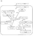
- FIG. The block diagram of the contamination range identification apparatus 100 in Embodiment 1.
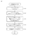
- FIG. The flowchart of the contamination range identification method in Embodiment 1.
- FIG. The figure which shows the intrusion route data 192 in Embodiment 1.
- FIG. The figure which shows the contamination object data 193 in Embodiment 1.
- FIG. The flowchart of the relationship construction (S110) in Embodiment 1.
- FIG. The figure which shows the object relation data 195A in Embodiment 3.
- FIG. The figure which shows the object relation data 195D in Embodiment 3.
- FIG. The figure which shows the object relation data 195G in Embodiment 3.
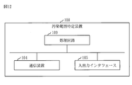
- FIG. The hardware block diagram of the contamination range identification apparatus 100 in embodiment.
- the same element or the corresponding element is designated by the same reference numeral.
- the description of the elements with the same reference numerals as the described elements will be omitted or abbreviated as appropriate.
- the arrows in the figure mainly indicate the flow of data or the flow of processing.
- Embodiment 1 The contamination range identification device 100 will be described with reference to FIGS. 1 to 7.
- the configuration of the contamination range specifying device 100 is a computer including hardware such as a processor 101, a memory 102, an auxiliary storage device 103, a communication device 104, and an input / output interface 105. These hardware are connected to each other via signal lines.
- the processor 101 is an IC that performs arithmetic processing and controls other hardware.
- the processor 101 is a CPU, DSP or GPU.
- IC is an abbreviation for Integrated Circuit.
- CPU is an abbreviation for Central Processing Unit.
- DSP is an abbreviation for Digital Signal Processor.
- GPU is an abbreviation for Graphics Processing Unit.
- the memory 102 is a volatile or non-volatile storage device.
- the memory 102 is also called a main storage device or a main memory.
- the memory 102 is a RAM.
- the data stored in the memory 102 is stored in the auxiliary storage device 103 as needed.
- RAM is an abbreviation for Random Access Memory.
- the auxiliary storage device 103 is a non-volatile storage device.
- the auxiliary storage device 103 is a ROM, HDD, or flash memory.
- the data stored in the auxiliary storage device 103 is loaded into the memory 102 as needed.
- ROM is an abbreviation for Read Only Memory.
- HDD is an abbreviation for Hard Disk Drive.
- the communication device 104 is a receiver and a transmitter.
- the communication device 104 is a communication chip or NIC.
- NIC is an abbreviation for Network Interface Card.
- the input / output interface 105 is a port to which an input device and an output device are connected.
- the input / output interface 105 is a USB terminal
- the input device is a keyboard and a mouse
- the output device is a display.
- USB is an abbreviation for Universal Serial Bus.
- the contamination range specifying device 100 includes elements such as a reception unit 110, a relationship building unit 120, a contamination range specifying unit 130, and an output unit 140. These elements are realized in software.
- the auxiliary storage device 103 stores a contamination range identification program for operating the computer as a reception unit 110, a relationship building unit 120, a contamination range identification unit 130, and an output unit 140.
- the pollution range identification program is loaded into the memory 102 and executed by the processor 101.
- the OS is further stored in the auxiliary storage device 103. At least part of the OS is loaded into memory 102 and executed by processor 101.
- the processor 101 executes the contamination range identification program while executing the OS.
- OS is an abbreviation for Operating System.
- the input / output data of the contamination range identification program is stored in the storage unit 190.
- the memory 102 functions as a storage unit 190.
- a storage device such as an auxiliary storage device 103, a register in the processor 101, and a cache memory in the processor 101 may function as a storage unit 190 instead of the memory 102 or together with the memory 102.
- the contamination range identification device 100 may include a plurality of processors that replace the processor 101.
- the plurality of processors share the functions of the processor 101.
- the contamination range identification program can be recorded (stored) in a computer-readable manner on a non-volatile recording medium such as an optical disk or a flash memory.
- the operation procedure of the contamination range identification device 100 corresponds to the contamination range identification method. Further, the operation procedure of the contamination range identification device 100 corresponds to the procedure of processing by the contamination range identification program.
- step S110 the relationship building unit 120 generates object-relational data based on the plurality of software operation data.
- Software operation data is data indicating software operation.
- Software operation is an operation generated by executing software. An example of software operation is shown below. (1) Start the process. (2) The process ends. (3) Communication. (4) Write a file. (5) Read the file. (6) Change file permissions. (7) System call. (8) Application operation. (9) Authentication (success). (10) Authentication (failure). (11) Policy violation
- log data such as communication logs, OS logs, file operation logs, application logs, and memory operation logs.
- the log data is output from, for example, an OS or an application.
- Software operation data includes operation type, operation object information, and operation time.
- the operation type is the type of software operation.
- the action object information indicates a plurality of software objects used in the software action.
- a software object is an element used when running software.
- An example of a software object is shown below.
- Files such as data files or program files.
- Each data is used in the process.
- Process. The process is each instance after the program file has been executed.
- the action object information indicates an action object and a target object.
- An action object is a software object that performs software actions. That is, the action object is a software object that is the main body of the software action.
- a specific example of a motion object is a process.
- the target object is a software object that is the target of software operation. That is, the target object is a software object that is an object of software operation.
- a specific example of the target object is a file.
- the operation time is the time when the software operation occurred.
- the object-relational data is data showing the relationship between a plurality of software objects.
- the object-relational data represents an object-relational graph.
- the object-relational graph has a node for each software object and an edge for each set of nodes. Nodes represent software objects. Edges represent relationships between software objects.
- FIG. 3 shows object-relational data 191.
- the object-relational data 191 is an example of the object-relational data.
- the object-relational data 191 represents an object-relational graph 191G.
- the element in which the process name, the file name, or the log name is written is a node.
- the line connecting the nodes is the edge.
- the edge represented by the arrow line is a directed edge representing a directed relationship according to the motion type.
- the terms attached to the edges indicate the relationships according to the movement type.
- step S120 the pollution range specifying unit 130 generates pollution range data based on the object-related data and the alert data.
- the alert data is data for notifying the occurrence of a cyber attack, and includes anomalous object information.
- the anomalous object information indicates an anomalous object.
- Anomalous objects are software objects for which cyber attacks have been detected.
- the contamination range data is data indicating the contamination range, and includes intrusion route data and contamination object data.
- the area of pollution is the area affected by cyber attacks.
- the intrusion route data indicates the intrusion route of a cyber attack.
- the intrusion route of cyber attacks is included in the pollution range.
- Contaminated object data indicates contaminated objects. Contamination objects are software objects that are affected by cyber attacks.
- FIG. 4 shows intrusion route data 192.
- the intrusion route data 192 is an example of the intrusion route data.
- the intrusion route data 192 shows the intrusion route from the external process to the process 2.
- Process 2 is an abnormal object.
- FIG. 5 shows contaminated object data 193.
- the contaminated object data 193 is an example of contaminated object data.
- Contamination object data 193 shows each software object on the intrusion route, as well as each software object affected by process 2.
- step S130 the output unit 140 outputs the contamination range data. That is, the output unit 140 outputs the intrusion route data and the contaminated object data.
- step S111 the reception unit 110 receives software operation data. Specifically, software operation data is input to the contamination range identification device 100. Then, the reception unit 110 receives the input software operation data and stores it in the storage unit 190.
- the software operation data may be input by the user, may be input by communication with the monitoring target, or may be input by other methods.
- step S112 the relationship building unit 120 extracts the operation type and the operation object information from the software operation data.
- step S113 the relationship building unit 120 updates the object-related data based on the operation type and the operation object information.
- Object-relational data is updated as follows.
- Object-relational data represents an object-relational graph.
- the motion object information indicates two software objects, a motion object and a target object.
- the relationship building unit 120 searches the object relationship graph for a node representing each software object shown in the action object information.
- the relationship building unit 120 newly generates a node that was not found, and adds the generated node to the object-relational graph.
- the relationship building unit 120 selects an action object node and a target object node from the object relationship graph.
- An action object node is a node that represents an action object
- a target object node is a node that represents a target object.
- the relationship building unit 120 generates an edge connecting the two selected nodes, and adds the generated edge to the object-relational graph. Specifically, the relationship building unit 120 specifies the directed relationship between the action object and the target object according to the action type, and adds a directed edge from the action object node to the target object node. The directed edge has an orientation that represents the identified directed relationship.
- object-relational data 191 (see FIG. 3) is generated.
- step S121 the reception unit 110 receives the alert data. Specifically, alert data is input to the contamination range identification device 100. Then, the reception unit 110 receives the input alert data and stores it in the storage unit 190.
- the alert data may be input by the user, may be input by communication with the attack detection device, or may be input by other methods.
- the attack detection device is a device that monitors the monitoring target, detects the cyber attack that has occurred, and outputs alert data.
- step S122 the contamination range specifying unit 130 extracts abnormal object information from the alert data.
- step S123 the pollution range specifying unit 130 identifies the intrusion route from the abnormal object node to the external process node by using the object-relational graph.
- the intrusion route is specified as follows. Each edge in the object-relational graph is a directed edge. First, the pollution range specifying unit 130 selects an abnormal object node from the object-relational graph. Anomalous object nodes are nodes that represent anomalous objects. Then, the contamination range specifying unit 130 traces each directed edge in the opposite direction from the abnormal object node to the external process node. An external process node is a node that represents an external process. An external process is a process generated outside the monitored object. The route from the anomalous object node to the external process node is the intrusion route.
- step S124 the contamination range specifying unit 130 identifies a contaminated object by using an object-relational graph.
- Contaminated objects are identified as follows:
- the pollution range identification unit 130 selects each node located in the intrusion route from the object-relational graph.
- the software object represented by each selected node is a contaminated object.
- the contamination range specifying unit 130 traces each directed edge in the forward direction from each node located in the intrusion route.
- the software object represented by each node you follow is a polluted object.
- step S125 the contamination range identification unit 130 generates contamination range data. That is, the contamination range specifying unit 130 generates intrusion route data and contamination object data.
- the intrusion route data is generated as follows.
- the contamination range identification unit 130 generates data indicating the intrusion route identified in step S123.
- the generated data is intrusion route data.
- Contamination object data is generated as follows.
- the contamination range identification unit 130 generates data indicating the contamination object identified in step S124.
- the data generated is contaminated object data.
- the intrusion route data 192 (see FIG. 4) and the contaminated object data 193 (see FIG. 5) are generated.
- the anomalous object is process 2.
- step S111 the reception unit 110 receives log data indicating the end of the process.
- step S112 the relationship building unit 120 extracts the operation type and the operation object information from the log data.
- the operation type is process termination.
- the action object is the instruction process, and the target object is the termination process.
- step S113 the relationship building unit 120 adds the action object node to the object relationship graph if there is no action object node in the object relationship graph. Further, the relationship building unit 120 adds the target object node to the object relationship graph if there is no target object node in the object relationship graph. Then, the relationship building unit 120 adds an edge from the action object node to the target object node to the object relationship graph. Relationships are added to the edges according to the operation type.
- step S111 the reception unit 110 receives log data indicating communication.
- step S112 the relationship building unit 120 extracts the operation type and the operation object information from the log data.
- the operation type is communication.
- the operation object is the communication source process
- the target object is the communication destination process.
- each process is identified by an external address.
- the external address is an address that identifies an external device to be monitored.
- step S113 the relationship building unit 120 adds the action object node to the object relationship graph if there is no action object node in the object relationship graph. Further, the relationship building unit 120 adds the target object node to the object relationship graph if there is no target object node in the object relationship graph.
- the action object information indicates an external address as an identifier of the action object or the target object
- a node representing the external process is generated.
- the relationship building unit 120 adds an edge from the action object node to the target object node to the object relationship graph. Relationships are added to the edges according to the operation type.
- step S111 the reception unit 110 receives log data indicating a file operation (write).
- step S112 the relationship building unit 120 extracts the operation type and the operation object information from the log data.
- the operation type is file write.
- the action object is a process and the target object is a file.
- step S113 the relationship building unit 120 adds the action object node to the object relationship graph if there is no action object node in the object relationship graph. Further, the relationship building unit 120 adds the target object node to the object relationship graph if there is no target object node in the object relationship graph. Then, the relationship building unit 120 adds an edge from the action object node to the target object node to the object relationship graph. Relationships are added to the edges according to the operation type.
- step S111 the reception unit 110 receives log data indicating a file operation (read).
- step S112 the relationship building unit 120 extracts the operation type and the operation object information from the log data.
- the operation type is file reading.
- the action object is a process and the target object is a file.
- step S113 the relationship building unit 120 adds the action object node to the object relationship graph if there is no action object node in the object relationship graph. Further, the relationship building unit 120 adds the target object node to the object relationship graph if there is no target object node in the object relationship graph. Then, the relationship building unit 120 adds an edge from the action object node to the target object node to the object relationship graph. Relationships are added to the edges according to the operation type.
- step S111 the reception unit 110 receives log data indicating a file operation (authority change).
- step S112 the relationship building unit 120 extracts the operation type and the operation object information from the log data.
- the operation type is file permission change.
- the action object is a process and the target object is a file.
- step S113 the relationship building unit 120 adds the action object node to the object relationship graph if there is no action object node in the object relationship graph. Further, the relationship building unit 120 adds the target object node to the object relationship graph if there is no target object node in the object relationship graph. Then, the relationship building unit 120 adds an edge from the action object node to the target object node to the object relationship graph. Relationships are added to the edges according to the operation type.
- step S111 the reception unit 110 receives log data indicating an OS system call.
- step S112 the relationship building unit 120 extracts the operation type and the operation object information from the log data.
- the operation type is system call.
- the type of system call is identified by, for example, a name.
- the action object is a process and the target object is a process or file.
- step S113 the relationship building unit 120 adds the action object node to the object relationship graph if there is no action object node in the object relationship graph. Further, the relationship building unit 120 adds the target object node to the object relationship graph if there is no target object node in the object relationship graph. Then, the relationship building unit 120 adds an edge from the action object node to the target object node to the object relationship graph. Relationships are added to the edges according to the operation type.
- step S111 the reception unit 110 receives log data indicating the application operation.
- step S112 the relationship building unit 120 extracts the operation type and the operation object information from the log data.
- the operation type is application operation.
- the type of application behavior is identified, for example, by name.
- the action object is a process and the target object is a process or file.
- step S113 the relationship building unit 120 adds the action object node to the object relationship graph if there is no action object node in the object relationship graph. Further, the relationship building unit 120 adds the target object node to the object relationship graph if there is no target object node in the object relationship graph. Then, the relationship building unit 120 adds an edge from the action object node to the target object node to the object relationship graph. Relationships are added to the edges according to the operation type.
- step S111 the reception unit 110 receives the log data indicating security.
- security is authentication.
- step S112 the relationship building unit 120 extracts the operation type and the operation object information from the log data.
- the operation type is authentication success, authentication failure, or policy violation.
- the action object is a process
- the target object is a process.
- step S113 the relationship building unit 120 adds the action object node to the object relationship graph if there is no action object node in the object relationship graph. Further, the relationship building unit 120 adds the target object node to the object relationship graph if there is no target object node in the object relationship graph. Then, the relationship building unit 120 adds an edge from the action object node to the target object node to the object relationship graph. Relationships are added to the edges according to the operation type.
- the contamination range identification device 100 can identify an intrusion route and a contaminated portion (contaminated object).
- the pollution range identification device 100 can centrally manage the relationship between a plurality of software objects by means of an object relationship graph. This allows for rapid identification of entry routes and contaminated areas. By identifying the intrusion route and the contaminated part, it is possible to remove the contaminated part and take measures to prevent recurrence.
- Embodiment 2 The form of generating the object-relational data including the relationship between the three software objects will be described mainly different from the first embodiment with reference to FIG.
- step S111 the reception unit 110 receives software operation data.
- Software operation data includes operation type and operation object information.
- the motion object information indicates three software objects used in the software motion identified by the motion type.
- step S112 the relationship building unit 120 extracts the operation type and the operation object information from the software operation data.
- step S113 the relationship building unit 120 updates the object-related data based on the operation type and the object information.
- Object-relational data is updated as follows.
- Object-relational data represents an object-relational graph.
- the motion object information indicates three software objects, that is, a first object, a second object, and a third object.
- the relationship building unit 120 searches the object relationship graph for a node representing each software object shown in the action object information.
- the relationship building unit 120 adds the missing node to the object relationship graph.
- the relationship building unit 120 selects the first object node and the third object node from the object relationship graph.
- the first object node is a node representing the first object
- the third object node is a node representing the third object.
- the relationship building unit 120 adds an edge connecting the two selected nodes to the object relationship graph.
- the relationship building unit 120 adds a directed edge from the first object node to the third object node.
- the relationship building unit 120 selects a second object node and a third object node from the object relationship graph.
- the second object node is a node that represents the second object.
- the relationship building unit 120 adds an edge connecting the two selected nodes to the object relationship graph.
- the relationship building unit 120 adds a directed edge from the third object node to the second object node.
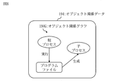
- FIG. 8 shows object-relational data 194.
- the object-relational data 194 represents an object-relational graph 194G.
- the reception unit 110 receives the log data indicating the process start.
- the relationship building unit 120 extracts the operation type and the operation object information from the log data.
- the operation type is process startup.
- the first object is the parent process
- the second object is the child process
- the third object is the program file.
- the relationship building unit 120 adds the first object node to the object relationship graph if the object relationship graph does not have the first object node.
- the relationship building unit 120 adds the second object node to the object relationship graph if the object relationship graph does not have the second object node. Further, the relationship building unit 120 adds the third object node to the object relationship graph if the object relationship graph does not have the third object node. Then, the relationship building unit 120 adds an edge from the first object node to the third object node to the object relationship graph. Further, the relationship building unit 120 adds an edge from the third object node to the second object node to the object relationship graph. A relationship is added to each edge according to the operation type.
- the contamination range identification device 100 can manage not only the relationship between two software objects but also the relationship between three software objects.
- Embodiment 3 The form of adding a profile to each node and each edge in the object-relational graph will be described mainly different from the first embodiment with reference to FIGS. 9 to 11.
- step S111 the reception unit 110 receives software operation data.
- step S112 the relationship building unit 120 extracts the operation type, the operation object information, and the operation time from the software operation data.
- step S113 the relationship building unit 120 updates the object-related data based on the operation type, the object information, and the operation time.
- Object-relational data is updated as follows.
- Object-relational data represents an object-relational graph.
- the motion object information indicates two software objects, a motion object and a target object.
- the relationship building unit 120 searches the object relationship graph for a node representing each software object shown in the action object information.
- the relationship building unit 120 updates the profile attached to the found node. Specifically, the update time in the profile is updated to the current operation time, that is, the latest operation time.
- the relationship building unit 120 adds the missing node to the object relationship graph. Further, the relationship building unit 120 generates a profile for the added node and adds the generated profile to the added node.
- the profile for a node contains the node identifier, node type and modification time.
- a node identifier identifies a node.
- the node type identifies the type of software object represented by the node. Specific examples of node types are processes, data files, program files and log files.
- the update time is the current operation time, that is, the latest operation time.
- the relationship building unit 120 selects an action object node and a target object node from the object relationship graph.
- the relationship building unit 120 adds an edge connecting the two selected nodes to the object relationship graph. Specifically, the relationship building unit 120 adds a directed edge from the action object node to the target object node. Further, the relationship building unit 120 generates a profile for the added edge and adds the generated profile to the added edge.
- the profile for the edge contains the edge identifier, the edge type and the modification time.
- the edge type identifies the relationship according to the operation type. That is, the edge type identifies the relationship between two software objects connected by an edge.
- the update time is the current operation time, that is, the latest operation time.
- step S111 the reception unit 110 receives log data indicating communication.
- the log data may include communication data information.
- the communication data information indicates communication data, the amount of communication data, and the like.
- step S112 the relationship building unit 120 extracts the operation type, the operation object information, and the operation time from the log data.
- the operation type is communication.
- the operation object is the communication source process, and the target object is the communication destination process. If the destination process or the destination process is identified by an external address, the process is an external process.
- the relationship building unit 120 may extract communication data information from the log data.
- step S113 if there is no action object node in the object relationship graph, the relationship building unit 120 adds the action object node and the profile for the action object node to the object relationship graph. If there is no target object node in the object relationship graph, the relationship building unit 120 adds the target object node and the profile for the target object node to the object relationship graph.
- Each profile added contains a node identifier, a node type, a generation time, and an update time.
- the node type is process.
- Each of the generation time and the update time is the same as the operation time extracted from the log data.
- the relationship building unit 120 updates the update time in the profile for the node to the operation time extracted from the log data. Further, the relationship building unit 120 adds an edge from the action object node to the target object node and its edge profile to the object relationship graph. Relationships are added to the edges according to the operation type.
- An edge profile is a profile for an edge and includes an edge identifier, an edge type, a generation time, and an update time. Each of the generation time and the update time is the same as the operation time extracted from the log data.
- the relationship building unit 120 may include communication data information in each profile.
- FIG. 9 shows object-relational data 195A.
- the object-relational data 195A represents an object-relational graph 195B.
- the object relationship graph 195B includes an edge profile 195C.
- the edge profile 195C is a profile for the edge from the communication source process to the communication log.
- FIG. 10 shows object-relational data 195D.
- the object-relational data 195D represents an object-relational graph 195E.
- the object-relational graph 195E includes an edge profile 195F.
- the edge profile 195F is a profile for the edge from the communication destination process to the communication log.
- FIG. 11 shows object-relational data 195G.
- the object-relational data 195G represents an object-relational graph 195H.
- the object relationship graph 195H includes an edge profile 195I.
- the edge profile 195I is a profile for the edge from the communication source process to the communication destination process.
- the contamination range identification device 100 can add a profile to each node and each edge. That is, each software object and the relationship between the software objects can be managed in more detail. Each profile has time information. This makes it possible to identify the intrusion route and the contaminated part with high accuracy without any time-series inconsistency.
- the second embodiment may be applied to the third embodiment. That is, the object-relational data in the third embodiment may include the relationship between the three software objects as in the object-relational graph in the second embodiment.
- Embodiment 4 The mode in which the valid flag is added to each node profile is mainly different from the third embodiment.
- the method for identifying the contamination range is the same as the method in the first embodiment (see FIG. 2).
- the relationship construction (S110) adds a profile to each node and each edge in the object-relational graph. And the profile for each node contains a valid flag. The valid flag indicates whether the software object is valid or not.
- step S111 the reception unit 110 receives software operation data.
- step S112 the relationship building unit 120 extracts the operation type, the operation object information, and the operation time from the software operation data.
- step S113 the relationship building unit 120 updates the object-related data based on the operation type, the object information, and the operation time.
- Object-relational data is updated as follows.
- Object-relational data represents an object-relational graph.
- the motion object information indicates two software objects, a motion object and a target object.
- the relationship building unit 120 searches the object relationship graph for a node representing each software object shown in the action object information.
- the relationship building unit 120 updates the profile attached to the found node. Specifically, the update time in the profile is updated to the current operation time. Further, the relationship building unit 120 determines whether the operation type identifies an object invalid operation.
- the object invalidation operation is a software operation in which a software object is invalidated. For example, object invalid actions include process termination or file deletion.
- the relationship building unit 120 updates the value of the valid flag in the profile to the invalid value.
- An invalid value is a value that means invalid.
- the relationship building unit 120 adds the missing node to the object relationship graph. Further, the relationship building unit 120 generates a profile for the added node and adds the generated profile to the added node.
- the profile for the node contains the node identifier, node type, modification time and valid flag. The initial value of the valid flag is a valid value.
- a valid value is a value that means valid.
- the relationship building unit 120 selects an action object node and a target object node from the object relationship graph.
- the relationship building unit 120 adds an edge connecting the two selected nodes to the object relationship graph. Specifically, the relationship building unit 120 adds a directed edge from the action object node to the target object node. Further, the relationship building unit 120 generates a profile for the added edge and adds the generated profile to the added edge.
- the profile for the edge contains the edge identifier, the edge type and the modification time.
- step S111 the reception unit 110 receives log data indicating the end of the process.
- step S112 the relationship building unit 120 extracts the operation type, the operation object information, and the operation time from the log data.
- the operation type is process termination.
- the action object is the instruction process, and the target object is the termination process.
- step S113 the action object node is not in the object-relational graph, and the target object node is in the object-relational graph.
- the relationship building unit 120 adds the action object node and the profile for the action object node to the object relationship graph.
- the profile added includes the node identifier, node type, generation time, modification time, and valid flag.
- the node type is process. Each of the generation time and the update time is the same as the operation time extracted from the log data.
- the valid flag indicates a valid value.
- the relationship building unit 120 updates the update time in the profile for the target object node to the operation time extracted from the log data. Further, the relationship building unit 120 updates the value of the valid flag in the profile for the target object node to an invalid value. Further, the relationship building unit 120 adds an edge from the action object node to the target object node and its edge profile to the object relationship graph. Relationships are added to the edges according to the operation type.
- An edge profile is a profile for an edge and includes an edge identifier, an edge type, a generation time, and an update time. Each of the generation time and the update time is the same as the operation time extracted from the log data.
- the pollution range identification device 100 can include a valid flag in the profile for each node. This makes it possible to identify the intrusion route and the contaminated part with higher accuracy.
- the contamination range identification device 100 includes a processing circuit 109.
- the processing circuit 109 is hardware that realizes the reception unit 110, the relationship building unit 120, the contamination range specifying unit 130, and the output unit 140.
- the processing circuit 109 may be dedicated hardware or a processor 101 that executes a program stored in the memory 102.
- the processing circuit 109 is dedicated hardware, the processing circuit 109 is, for example, a single circuit, a composite circuit, a programmed processor, a parallel programmed processor, an ASIC, an FPGA, or a combination thereof.
- ASIC is an abbreviation for Application Special Integrated Circuit.
- FPGA is an abbreviation for Field Programmable Gate Array.
- the contamination range identification device 100 may include a plurality of processing circuits that replace the processing circuit 109.
- the plurality of processing circuits share the functions of the processing circuit 109.
- processing circuit 109 some functions may be realized by dedicated hardware, and the remaining functions may be realized by software or firmware.
- the function of the contamination range identification device 100 can be realized by hardware, software, firmware, or a combination thereof.
- Each embodiment is an example of a preferred embodiment and is not intended to limit the technical scope of the present disclosure. Each embodiment may be partially implemented or may be implemented in combination with other embodiments. The procedure described using the flowchart or the like may be appropriately changed.
- the "part” which is an element of the contamination range specifying device 100 may be read as “treatment” or "process”.
- 100 pollution range identification device 101 processor, 102 memory, 103 auxiliary storage device, 104 communication device, 105 input / output interface, 109 processing circuit, 110 reception section, 120 relationship construction section, 130 pollution range identification section, 140 output section, 190 Storage unit, 191 object-related data, 191G object-related graph, 192 intrusion route data, 193 contaminated object data, 194 object-related data, 194G object-related graph, 195A object-related data, 195B object-related graph, 195C edge profile.
Landscapes
- Engineering & Computer Science (AREA)
- Computer Security & Cryptography (AREA)
- Theoretical Computer Science (AREA)
- Software Systems (AREA)
- Computer Hardware Design (AREA)
- General Engineering & Computer Science (AREA)
- General Physics & Mathematics (AREA)
- Physics & Mathematics (AREA)
- Virology (AREA)
- Health & Medical Sciences (AREA)
- General Health & Medical Sciences (AREA)
- Quality & Reliability (AREA)
- Debugging And Monitoring (AREA)
Abstract
関係構築部(120)は、ソフトウェア動作の動作タイプと前記ソフトウェア動作で使用された複数のソフトウェアオブジェクトを示す動作オブジェクト情報とをそれぞれが含む複数のソフトウェア動作データに基づいて、前記複数のソフトウェアオブジェクトの関係を示すオブジェクト関係データを生成する。汚染範囲特定部(130)は、前記オブジェクト関係データと、サイバー攻撃の発生を知らせるアラートデータと、に基づいて、サイバー攻撃の影響を受ける汚染範囲を示す汚染範囲データを生成する。
Description
本開示は、サイバー攻撃による汚染の再発防止に関するものである。
サイバー攻撃に対して次のような対処がされる。
まず、監視対象に対するサイバー攻撃が検知される。
次に、サイバー攻撃の影響が判断される。
そして、サイバー攻撃の影響に応じて監視対象の縮退動作が決定される。例えば、縮退動作において、機能の切替えまたは機能の再配置が行われる。
まず、監視対象に対するサイバー攻撃が検知される。
次に、サイバー攻撃の影響が判断される。
そして、サイバー攻撃の影響に応じて監視対象の縮退動作が決定される。例えば、縮退動作において、機能の切替えまたは機能の再配置が行われる。
また、サイバー攻撃の影響に対して、汚染部分の除去および再発防止の対応を実施する必要がある。
汚染部分の除去は、汚染部分の削除、復元または初期化などを意味する。汚染部分は、サイバー攻撃によって改変された部分である。例えば、汚染部分は、改変されたコードおよび改変されたデータである。汚染部分の除去のためには、汚染部分を特定する必要がある。
再発防止の対応は、汚染部分を除去しただけではサイバー攻撃を再び受ける恐れがあるため、実施する必要がある。再発防止の具体的な対応は、サイバー攻撃の侵入経路を遮断することである。サイバー攻撃の侵入経路を遮断するためにはサイバー攻撃の侵入経路を特定する必要がある。
汚染部分の除去は、汚染部分の削除、復元または初期化などを意味する。汚染部分は、サイバー攻撃によって改変された部分である。例えば、汚染部分は、改変されたコードおよび改変されたデータである。汚染部分の除去のためには、汚染部分を特定する必要がある。
再発防止の対応は、汚染部分を除去しただけではサイバー攻撃を再び受ける恐れがあるため、実施する必要がある。再発防止の具体的な対応は、サイバー攻撃の侵入経路を遮断することである。サイバー攻撃の侵入経路を遮断するためにはサイバー攻撃の侵入経路を特定する必要がある。
特許文献1は、車載システムにおいてセキュリティ攻撃に起因する異常が発生した場合であっても自動車の走行制御を安全な状態に保つための技術を開示している。
特許文献1には、異常内容および異常個所に基づいて縮退動作を一意に決定することが開示されている。しかし、汚染部分の除去および再発防止の対応を実施するための方法は開示されていない。特に、侵入経路を特定する方法および汚染部分を特定する方法は開示されていない。
本開示は、侵入経路および汚染部分を特定できるようにすることを目的とする。
本開示の汚染範囲特定装置は、
ソフトウェア動作の動作タイプと前記ソフトウェア動作で使用された複数のソフトウェアオブジェクトを示す動作オブジェクト情報とをそれぞれが含む複数のソフトウェア動作データに基づいて、前記複数のソフトウェアオブジェクトの関係を示すオブジェクト関係データを生成する関係構築部と、
前記オブジェクト関係データと、サイバー攻撃の発生を知らせるアラートデータと、に基づいて、サイバー攻撃の影響を受ける汚染範囲を示す汚染範囲データを生成する汚染範囲特定部と、を備える。
ソフトウェア動作の動作タイプと前記ソフトウェア動作で使用された複数のソフトウェアオブジェクトを示す動作オブジェクト情報とをそれぞれが含む複数のソフトウェア動作データに基づいて、前記複数のソフトウェアオブジェクトの関係を示すオブジェクト関係データを生成する関係構築部と、
前記オブジェクト関係データと、サイバー攻撃の発生を知らせるアラートデータと、に基づいて、サイバー攻撃の影響を受ける汚染範囲を示す汚染範囲データを生成する汚染範囲特定部と、を備える。
本開示によれば、侵入経路および汚染部分といった汚染範囲を特定することが可能となる。
実施の形態および図面において、同じ要素または対応する要素には同じ符号を付している。説明した要素と同じ符号が付された要素の説明は適宜に省略または簡略化する。図中の矢印はデータの流れ又は処理の流れを主に示している。
実施の形態1.
汚染範囲特定装置100について、図1から図7に基づいて説明する。
汚染範囲特定装置100について、図1から図7に基づいて説明する。
***構成の説明***
図1に基づいて、汚染範囲特定装置100の構成を説明する。
汚染範囲特定装置100は、プロセッサ101とメモリ102と補助記憶装置103と通信装置104と入出力インタフェース105といったハードウェアを備えるコンピュータである。これらのハードウェアは、信号線を介して互いに接続されている。
図1に基づいて、汚染範囲特定装置100の構成を説明する。
汚染範囲特定装置100は、プロセッサ101とメモリ102と補助記憶装置103と通信装置104と入出力インタフェース105といったハードウェアを備えるコンピュータである。これらのハードウェアは、信号線を介して互いに接続されている。
プロセッサ101は、演算処理を行うICであり、他のハードウェアを制御する。例えば、プロセッサ101は、CPU、DSPまたはGPUである。
ICは、Integrated Circuitの略称である。
CPUは、Central Processing Unitの略称である。
DSPは、Digital Signal Processorの略称である。
GPUは、Graphics Processing Unitの略称である。
ICは、Integrated Circuitの略称である。
CPUは、Central Processing Unitの略称である。
DSPは、Digital Signal Processorの略称である。
GPUは、Graphics Processing Unitの略称である。
メモリ102は揮発性または不揮発性の記憶装置である。メモリ102は、主記憶装置またはメインメモリとも呼ばれる。例えば、メモリ102はRAMである。メモリ102に記憶されたデータは必要に応じて補助記憶装置103に保存される。
RAMは、Random Access Memoryの略称である。
RAMは、Random Access Memoryの略称である。
補助記憶装置103は不揮発性の記憶装置である。例えば、補助記憶装置103は、ROM、HDDまたはフラッシュメモリである。補助記憶装置103に記憶されたデータは必要に応じてメモリ102にロードされる。
ROMは、Read Only Memoryの略称である。
HDDは、Hard Disk Driveの略称である。
ROMは、Read Only Memoryの略称である。
HDDは、Hard Disk Driveの略称である。
通信装置104はレシーバ及びトランスミッタである。例えば、通信装置104は通信チップまたはNICである。
NICは、Network Interface Cardの略称である。
NICは、Network Interface Cardの略称である。
入出力インタフェース105は、入力装置および出力装置が接続されるポートである。例えば、入出力インタフェース105はUSB端子であり、入力装置はキーボードおよびマウスであり、出力装置はディスプレイである。
USBは、Universal Serial Busの略称である。
USBは、Universal Serial Busの略称である。
汚染範囲特定装置100は、受付部110と関係構築部120と汚染範囲特定部130と出力部140といった要素を備える。これらの要素はソフトウェアで実現される。
補助記憶装置103には、受付部110と関係構築部120と汚染範囲特定部130と出力部140としてコンピュータを機能させるための汚染範囲特定プログラムが記憶されている。汚染範囲特定プログラムは、メモリ102にロードされて、プロセッサ101によって実行される。
補助記憶装置103には、さらに、OSが記憶されている。OSの少なくとも一部は、メモリ102にロードされて、プロセッサ101によって実行される。
プロセッサ101は、OSを実行しながら、汚染範囲特定プログラムを実行する。
OSは、Operating Systemの略称である。
補助記憶装置103には、さらに、OSが記憶されている。OSの少なくとも一部は、メモリ102にロードされて、プロセッサ101によって実行される。
プロセッサ101は、OSを実行しながら、汚染範囲特定プログラムを実行する。
OSは、Operating Systemの略称である。
汚染範囲特定プログラムの入出力データは記憶部190に記憶される。
メモリ102は記憶部190として機能する。但し、補助記憶装置103、プロセッサ101内のレジスタおよびプロセッサ101内のキャッシュメモリなどの記憶装置が、メモリ102の代わりに、又は、メモリ102と共に、記憶部190として機能してもよい。
メモリ102は記憶部190として機能する。但し、補助記憶装置103、プロセッサ101内のレジスタおよびプロセッサ101内のキャッシュメモリなどの記憶装置が、メモリ102の代わりに、又は、メモリ102と共に、記憶部190として機能してもよい。
汚染範囲特定装置100は、プロセッサ101を代替する複数のプロセッサを備えてもよい。複数のプロセッサは、プロセッサ101の機能を分担する。
汚染範囲特定プログラムは、光ディスクまたはフラッシュメモリ等の不揮発性の記録媒体にコンピュータ読み取り可能に記録(格納)することができる。
***動作の説明***
汚染範囲特定装置100の動作の手順は汚染範囲特定方法に相当する。また、汚染範囲特定装置100の動作の手順は汚染範囲特定プログラムによる処理の手順に相当する。
汚染範囲特定装置100の動作の手順は汚染範囲特定方法に相当する。また、汚染範囲特定装置100の動作の手順は汚染範囲特定プログラムによる処理の手順に相当する。
図2に基づいて、汚染範囲特定方法を説明する。
ステップS110において、関係構築部120は、複数のソフトウェア動作データに基づいて、オブジェクト関係データを生成する。
ステップS110において、関係構築部120は、複数のソフトウェア動作データに基づいて、オブジェクト関係データを生成する。
ソフトウェア動作データは、ソフトウェア動作を示すデータである。
ソフトウェア動作は、ソフトウェアの実行によって発生した動作である。以下に、ソフトウェア動作の例を示す。
(1)プロセス起動。
(2)プロセス終了。
(3)通信。
(4)ファイル書き込み。
(5)ファイル読み込み。
(6)ファイル権限変更。
(7)システムコール。
(8)アプリケーション動作。
(9)認証(成功)。
(10)認証(失敗)。
(11)ポリシー違反
(1)プロセス起動。
(2)プロセス終了。
(3)通信。
(4)ファイル書き込み。
(5)ファイル読み込み。
(6)ファイル権限変更。
(7)システムコール。
(8)アプリケーション動作。
(9)認証(成功)。
(10)認証(失敗)。
(11)ポリシー違反
ソフトウェア動作データの具体例は、通信ログ、OSログ、ファイル操作ログ、アプリケーションログまたはメモリ操作ログなどのログデータである。ログデータは、例えば、OSまたはアプリケーションから出力される。
ソフトウェア動作データは、動作タイプと動作オブジェクト情報と動作時刻とを含む。
動作タイプは、ソフトウェア動作の種類である。
動作オブジェクト情報は、ソフトウェア動作で使用された複数のソフトウェアオブジェクトを示す。
ソフトウェアオブジェクトは、ソフトウェアの実行時に使用される要素である。以下に、ソフトウェアオブジェクトの例を示す。
(1)データファイルまたはプログラムファイルなどのファイル。
(2)データファイルの中の各データ。各データはプロセスで使用される。
(3)プロセス。プロセスは、プログラムファイルが実行された後の各インスタンスである。
ソフトウェアオブジェクトは、ソフトウェアの実行時に使用される要素である。以下に、ソフトウェアオブジェクトの例を示す。
(1)データファイルまたはプログラムファイルなどのファイル。
(2)データファイルの中の各データ。各データはプロセスで使用される。
(3)プロセス。プロセスは、プログラムファイルが実行された後の各インスタンスである。
具体的には、動作オブジェクト情報は、動作オブジェクトと対象オブジェクトとを示す。
動作オブジェクトは、ソフトウェア動作を行うソフトウェアオブジェクトである。つまり、動作オブジェクトは、ソフトウェア動作の主体となるソフトウェアオブジェクトである。動作オブジェクトの具体例はプロセスである。
対象オブジェクトは、ソフトウェア動作の対象となるソフトウェアオブジェクトである。つまり、対象オブジェクトはソフトウェア動作の客体となるソフトウェアオブジェクトである。対象オブジェクトの具体例はファイルである。
動作オブジェクトは、ソフトウェア動作を行うソフトウェアオブジェクトである。つまり、動作オブジェクトは、ソフトウェア動作の主体となるソフトウェアオブジェクトである。動作オブジェクトの具体例はプロセスである。
対象オブジェクトは、ソフトウェア動作の対象となるソフトウェアオブジェクトである。つまり、対象オブジェクトはソフトウェア動作の客体となるソフトウェアオブジェクトである。対象オブジェクトの具体例はファイルである。
動作時刻は、ソフトウェア動作が発生した時刻である。
オブジェクト関係データは、複数のソフトウェアオブジェクトの関係を示すデータである。具体的には、オブジェクト関係データは、オブジェクト関係グラフを表す。
オブジェクト関係グラフは、ソフトウェアオブジェクト毎にノードを有し、ノードの組毎にエッジを有する。
ノードは、ソフトウェアオブジェクトを表す。
エッジは、ソフトウェアオブジェクト間の関係を表す。
オブジェクト関係グラフは、ソフトウェアオブジェクト毎にノードを有し、ノードの組毎にエッジを有する。
ノードは、ソフトウェアオブジェクトを表す。
エッジは、ソフトウェアオブジェクト間の関係を表す。
図3に、オブジェクト関係データ191を示す。オブジェクト関係データ191は、オブジェクト関係データの一例である。
オブジェクト関係データ191は、オブジェクト関係グラフ191Gを表す。
オブジェクト関係グラフ191Gにおいて、プロセス名、ファイル名またはログ名が記されている要素がノードである。ノードを結ぶ線がエッジである。矢印線で表されたエッジは、動作タイプに応じた有向関係性を表す有向エッジである。エッジに付された用語は動作タイプに応じた関係性を示す。
オブジェクト関係データ191は、オブジェクト関係グラフ191Gを表す。
オブジェクト関係グラフ191Gにおいて、プロセス名、ファイル名またはログ名が記されている要素がノードである。ノードを結ぶ線がエッジである。矢印線で表されたエッジは、動作タイプに応じた有向関係性を表す有向エッジである。エッジに付された用語は動作タイプに応じた関係性を示す。
図2に戻り、説明を続ける。
関係構築(S110)の手順について後述する。
関係構築(S110)の手順について後述する。
ステップS120において、汚染範囲特定部130は、オブジェクト関係データとアラートデータとに基づいて、汚染範囲データを生成する。
アラートデータは、サイバー攻撃の発生を知らせるデータであり、異常オブジェクト情報を含む。
異常オブジェクト情報は、異常オブジェクトを示す。
異常オブジェクトは、サイバー攻撃が検知されたソフトウェアオブジェクトである。
異常オブジェクト情報は、異常オブジェクトを示す。
異常オブジェクトは、サイバー攻撃が検知されたソフトウェアオブジェクトである。
汚染範囲データは、汚染範囲を示すデータであり、侵入経路データと汚染オブジェクトデータとを含む。汚染範囲は、サイバー攻撃の影響を受ける範囲である。
侵入経路データは、サイバー攻撃の侵入経路を示す。サイバー攻撃の侵入経路は、汚染範囲に含まれる。
汚染オブジェクトデータは、汚染オブジェクトを示す。
汚染オブジェクトは、サイバー攻撃の影響を受けるソフトウェアオブジェクトである。
侵入経路データは、サイバー攻撃の侵入経路を示す。サイバー攻撃の侵入経路は、汚染範囲に含まれる。
汚染オブジェクトデータは、汚染オブジェクトを示す。
汚染オブジェクトは、サイバー攻撃の影響を受けるソフトウェアオブジェクトである。
図4に、侵入経路データ192を示す。侵入経路データ192は、侵入経路データの一例である。
侵入経路データ192は、外部プロセスからプロセス2までの侵入経路を示す。プロセス2が異常オブジェクトである。
侵入経路データ192は、外部プロセスからプロセス2までの侵入経路を示す。プロセス2が異常オブジェクトである。
図5に、汚染オブジェクトデータ193を示す。汚染オブジェクトデータ193は、汚染オブジェクトデータの一例である。
汚染オブジェクトデータ193は、侵入経路上の各ソフトウェアオブジェクトの他に、プロセス2から影響を受ける各ソフトウェアオブジェクトを示す。
汚染オブジェクトデータ193は、侵入経路上の各ソフトウェアオブジェクトの他に、プロセス2から影響を受ける各ソフトウェアオブジェクトを示す。
図2に戻り、説明を続ける。
汚染範囲特定(S130)の手順について後述する。
汚染範囲特定(S130)の手順について後述する。
ステップS130において、出力部140は、汚染範囲データを出力する。
つまり、出力部140は、侵入経路データと汚染オブジェクトデータとを出力する。
つまり、出力部140は、侵入経路データと汚染オブジェクトデータとを出力する。
図6に基づいて、関係構築(S110)の手順を説明する。
空のオブジェクト関係データが予め用意される。
ステップS111からステップS113は、ソフトウェア動作データごとに実行される。
空のオブジェクト関係データが予め用意される。
ステップS111からステップS113は、ソフトウェア動作データごとに実行される。
ステップS111において、受付部110は、ソフトウェア動作データを受け付ける。
具体的には、ソフトウェア動作データが汚染範囲特定装置100に入力される。そして、受付部110は、入力されたソフトウェア動作データを受け付けて記憶部190に記憶する。
ソフトウェア動作データは、利用者によって入力されてもよいし、監視対象との通信で入力されてもよいし、その他の方法で入力されてもよい。
具体的には、ソフトウェア動作データが汚染範囲特定装置100に入力される。そして、受付部110は、入力されたソフトウェア動作データを受け付けて記憶部190に記憶する。
ソフトウェア動作データは、利用者によって入力されてもよいし、監視対象との通信で入力されてもよいし、その他の方法で入力されてもよい。
ステップS112において、関係構築部120は、ソフトウェア動作データから、動作タイプと動作オブジェクト情報とを抽出する。
ステップS113において、関係構築部120は、動作タイプと動作オブジェクト情報とに基づいて、オブジェクト関係データを更新する。
オブジェクト関係データは以下のように更新される。オブジェクト関係データはオブジェクト関係グラフを表す。動作オブジェクト情報は、動作オブジェクトと対象オブジェクトとの2つのソフトウェアオブジェクトを示す。
関係構築部120は、オブジェクト関係グラフの中から、動作オブジェクト情報に示される各ソフトウェアオブジェクトを表すノードを探す。
関係構築部120は、見つからなかったノードを新規に生成し、生成したノードをオブジェクト関係グラフに追加する。
関係構築部120は、オブジェクト関係グラフから、動作オブジェクトノードと対象オブジェクトノードを選択する。動作オブジェクトノードは動作オブジェクトを表すノードであり、対象オブジェクトノードは対象オブジェクトを表すノードである。
関係構築部120は、選択した2つのノードを結ぶエッジを生成し、生成したエッジをオブジェクト関係グラフに追加する。具体的には、関係構築部120は、動作オブジェクトと対象オブジェクトの有向関係性を動作タイプに応じて特定し、動作オブジェクトノードから対象オブジェクトノードへの有向エッジを追加する。有向エッジは、特定された有向関係性を表す向きを有する。
関係構築部120は、オブジェクト関係グラフの中から、動作オブジェクト情報に示される各ソフトウェアオブジェクトを表すノードを探す。
関係構築部120は、見つからなかったノードを新規に生成し、生成したノードをオブジェクト関係グラフに追加する。
関係構築部120は、オブジェクト関係グラフから、動作オブジェクトノードと対象オブジェクトノードを選択する。動作オブジェクトノードは動作オブジェクトを表すノードであり、対象オブジェクトノードは対象オブジェクトを表すノードである。
関係構築部120は、選択した2つのノードを結ぶエッジを生成し、生成したエッジをオブジェクト関係グラフに追加する。具体的には、関係構築部120は、動作オブジェクトと対象オブジェクトの有向関係性を動作タイプに応じて特定し、動作オブジェクトノードから対象オブジェクトノードへの有向エッジを追加する。有向エッジは、特定された有向関係性を表す向きを有する。
複数のソフトウェア動作データのそれぞれに対して関係構築(S110)が実行されることにより、例えば、オブジェクト関係データ191(図3参照)が生成される。
図7に基づいて、汚染範囲特定(S120)の手順を説明する。
ステップS121において、受付部110は、アラートデータを受け付ける。
具体的には、アラートデータが汚染範囲特定装置100に入力される。そして、受付部110は、入力されたアラートデータを受け付けて記憶部190に記憶する。
アラートデータは、利用者によって入力されてもよいし、攻撃検知装置との通信で入力されてもよいし、その他の方法で入力されてもよい。攻撃検知装置は、監視対象を監視し、発生したサイバー攻撃を検知し、アラートデータを出力する装置である。
ステップS121において、受付部110は、アラートデータを受け付ける。
具体的には、アラートデータが汚染範囲特定装置100に入力される。そして、受付部110は、入力されたアラートデータを受け付けて記憶部190に記憶する。
アラートデータは、利用者によって入力されてもよいし、攻撃検知装置との通信で入力されてもよいし、その他の方法で入力されてもよい。攻撃検知装置は、監視対象を監視し、発生したサイバー攻撃を検知し、アラートデータを出力する装置である。
ステップS122において、汚染範囲特定部130は、アラートデータから、異常オブジェクト情報を抽出する。
ステップS123において、汚染範囲特定部130は、オブジェクト関係グラフを用いて、異常オブジェクトノードから外部プロセスノードまでの侵入経路を特定する。
侵入経路は以下のように特定される。オブジェクト関係グラフの中の各エッジは有向エッジである。
まず、汚染範囲特定部130は、オブジェクト関係グラフの中から異常オブジェクトノードを選択する。異常オブジェクトノードは、異常オブジェクトを表すノードである。
そして、汚染範囲特定部130は、異常オブジェクトノードから外部プロセスノードまで各有向エッジを逆方向に辿る。外部プロセスノードは、外部プロセスを表すノードである。外部プロセスは、監視対象の外部で生成されたプロセスである。
異常オブジェクトノードから外部プロセスノードまでの経路が侵入経路である。
まず、汚染範囲特定部130は、オブジェクト関係グラフの中から異常オブジェクトノードを選択する。異常オブジェクトノードは、異常オブジェクトを表すノードである。
そして、汚染範囲特定部130は、異常オブジェクトノードから外部プロセスノードまで各有向エッジを逆方向に辿る。外部プロセスノードは、外部プロセスを表すノードである。外部プロセスは、監視対象の外部で生成されたプロセスである。
異常オブジェクトノードから外部プロセスノードまでの経路が侵入経路である。
ステップS124において、汚染範囲特定部130は、オブジェクト関係グラフを用いて、汚染オブジェクトを特定する。
汚染オブジェクトは以下のように特定される。
汚染範囲特定部130は、オブジェクト関係グラフから、侵入経路に位置する各ノードを選択する。選択される各ノードによって表されるソフトウェアオブジェクトは汚染オブジェクトである。
さらに、汚染範囲特定部130は、侵入経路に位置する各ノードから各有向エッジを順方向に辿る。辿った先の各ノードで表されるソフトウェアオブジェクトは汚染オブジェクトである。
汚染範囲特定部130は、オブジェクト関係グラフから、侵入経路に位置する各ノードを選択する。選択される各ノードによって表されるソフトウェアオブジェクトは汚染オブジェクトである。
さらに、汚染範囲特定部130は、侵入経路に位置する各ノードから各有向エッジを順方向に辿る。辿った先の各ノードで表されるソフトウェアオブジェクトは汚染オブジェクトである。
ステップS125において、汚染範囲特定部130は、汚染範囲データを生成する。
つまり、汚染範囲特定部130は、侵入経路データと汚染オブジェクトデータとを生成する。
つまり、汚染範囲特定部130は、侵入経路データと汚染オブジェクトデータとを生成する。
侵入経路データは以下のように生成される。
汚染範囲特定部130は、ステップS123で特定された侵入経路を示すデータを生成する。生成されるデータが侵入経路データである。
汚染範囲特定部130は、ステップS123で特定された侵入経路を示すデータを生成する。生成されるデータが侵入経路データである。
汚染オブジェクトデータは以下のように生成される。
汚染範囲特定部130は、ステップS124で特定された汚染オブジェクトを示すデータを生成する。生成されるデータが汚染オブジェクトデータである。
汚染範囲特定部130は、ステップS124で特定された汚染オブジェクトを示すデータを生成する。生成されるデータが汚染オブジェクトデータである。
オブジェクト関係データ191(図3参照)を用いて汚染範囲特定(S120)が実行されることにより、侵入経路データ192(図4参照)および汚染オブジェクトデータ193(図5参照)が生成される。異常オブジェクトはプロセス2である。
***実施例の説明***
関係構築(S110)(図6を参照)の実施例を以下に示す。
関係構築(S110)(図6を参照)の実施例を以下に示す。
<実施例1>
ステップS111において、受付部110は、プロセス終了を示すログデータを受け取る。
ステップS112において、関係構築部120は、ログデータから、動作タイプと動作オブジェクト情報を抽出する。動作タイプはプロセス終了である。動作オブジェクトは指示プロセスであり、対象オブジェクトは終了プロセスである。
ステップS113において、関係構築部120は、オブジェクト関係グラフに動作オブジェクトノードがなければ、動作オブジェクトノードをオブジェクト関係グラフに追加する。また、関係構築部120は、オブジェクト関係グラフに対象オブジェクトノードがなければ、対象オブジェクトノードをオブジェクト関係グラフに追加する。そして、関係構築部120は、動作オブジェクトノードから対象オブジェクトノードへのエッジをオブジェクト関係グラフに追加する。エッジには動作タイプに応じた関係性が付記される。
ステップS111において、受付部110は、プロセス終了を示すログデータを受け取る。
ステップS112において、関係構築部120は、ログデータから、動作タイプと動作オブジェクト情報を抽出する。動作タイプはプロセス終了である。動作オブジェクトは指示プロセスであり、対象オブジェクトは終了プロセスである。
ステップS113において、関係構築部120は、オブジェクト関係グラフに動作オブジェクトノードがなければ、動作オブジェクトノードをオブジェクト関係グラフに追加する。また、関係構築部120は、オブジェクト関係グラフに対象オブジェクトノードがなければ、対象オブジェクトノードをオブジェクト関係グラフに追加する。そして、関係構築部120は、動作オブジェクトノードから対象オブジェクトノードへのエッジをオブジェクト関係グラフに追加する。エッジには動作タイプに応じた関係性が付記される。
<実施例2>
ステップS111において、受付部110は、通信を示すログデータを受け取る。
ステップS112において、関係構築部120は、ログデータから、動作タイプと動作オブジェクト情報を抽出する。動作タイプは通信である。動作オブジェクトは通信元プロセスであり、対象オブジェクトは通信先プロセスである。通信元プロセスと通信先プロセスとの各プロセスが外部プロセスである場合、各プロセスは外部アドレスで識別される。外部アドレスは、監視対象の外部の装置を識別するアドレスである。
ステップS113において、関係構築部120は、オブジェクト関係グラフに動作オブジェクトノードがなければ、動作オブジェクトノードをオブジェクト関係グラフに追加する。また、関係構築部120は、オブジェクト関係グラフに対象オブジェクトノードがなければ、対象オブジェクトノードをオブジェクト関係グラフに追加する。つまり、動作オブジェクト情報が動作オブジェクトまたは対象オブジェクトの識別子として外部アドレスを示す場合、外部プロセスを表すノードが生成される。そして、関係構築部120は、動作オブジェクトノードから対象オブジェクトノードへのエッジをオブジェクト関係グラフに追加する。エッジには動作タイプに応じた関係性が付記される。
ステップS111において、受付部110は、通信を示すログデータを受け取る。
ステップS112において、関係構築部120は、ログデータから、動作タイプと動作オブジェクト情報を抽出する。動作タイプは通信である。動作オブジェクトは通信元プロセスであり、対象オブジェクトは通信先プロセスである。通信元プロセスと通信先プロセスとの各プロセスが外部プロセスである場合、各プロセスは外部アドレスで識別される。外部アドレスは、監視対象の外部の装置を識別するアドレスである。
ステップS113において、関係構築部120は、オブジェクト関係グラフに動作オブジェクトノードがなければ、動作オブジェクトノードをオブジェクト関係グラフに追加する。また、関係構築部120は、オブジェクト関係グラフに対象オブジェクトノードがなければ、対象オブジェクトノードをオブジェクト関係グラフに追加する。つまり、動作オブジェクト情報が動作オブジェクトまたは対象オブジェクトの識別子として外部アドレスを示す場合、外部プロセスを表すノードが生成される。そして、関係構築部120は、動作オブジェクトノードから対象オブジェクトノードへのエッジをオブジェクト関係グラフに追加する。エッジには動作タイプに応じた関係性が付記される。
<実施例3>
ステップS111において、受付部110は、ファイル操作(write)を示すログデータを受け取る。
ステップS112において、関係構築部120は、ログデータから、動作タイプと動作オブジェクト情報を抽出する。動作タイプはファイル書込みである。動作オブジェクトはプロセスであり、対象オブジェクトはファイルである。
ステップS113において、関係構築部120は、オブジェクト関係グラフに動作オブジェクトノードがなければ、動作オブジェクトノードをオブジェクト関係グラフに追加する。また、関係構築部120は、オブジェクト関係グラフに対象オブジェクトノードがなければ、対象オブジェクトノードをオブジェクト関係グラフに追加する。そして、関係構築部120は、動作オブジェクトノードから対象オブジェクトノードへのエッジをオブジェクト関係グラフに追加する。エッジには動作タイプに応じた関係性が付記される。
ステップS111において、受付部110は、ファイル操作(write)を示すログデータを受け取る。
ステップS112において、関係構築部120は、ログデータから、動作タイプと動作オブジェクト情報を抽出する。動作タイプはファイル書込みである。動作オブジェクトはプロセスであり、対象オブジェクトはファイルである。
ステップS113において、関係構築部120は、オブジェクト関係グラフに動作オブジェクトノードがなければ、動作オブジェクトノードをオブジェクト関係グラフに追加する。また、関係構築部120は、オブジェクト関係グラフに対象オブジェクトノードがなければ、対象オブジェクトノードをオブジェクト関係グラフに追加する。そして、関係構築部120は、動作オブジェクトノードから対象オブジェクトノードへのエッジをオブジェクト関係グラフに追加する。エッジには動作タイプに応じた関係性が付記される。
<実施例4>
ステップS111において、受付部110は、ファイル操作(read)を示すログデータを受け取る。
ステップS112において、関係構築部120は、ログデータから、動作タイプと動作オブジェクト情報を抽出する。動作タイプはファイル読込みである。動作オブジェクトはプロセスであり、対象オブジェクトはファイルである。
ステップS113において、関係構築部120は、オブジェクト関係グラフに動作オブジェクトノードがなければ、動作オブジェクトノードをオブジェクト関係グラフに追加する。また、関係構築部120は、オブジェクト関係グラフに対象オブジェクトノードがなければ、対象オブジェクトノードをオブジェクト関係グラフに追加する。そして、関係構築部120は、動作オブジェクトノードから対象オブジェクトノードへのエッジをオブジェクト関係グラフに追加する。エッジには動作タイプに応じた関係性が付記される。
ステップS111において、受付部110は、ファイル操作(read)を示すログデータを受け取る。
ステップS112において、関係構築部120は、ログデータから、動作タイプと動作オブジェクト情報を抽出する。動作タイプはファイル読込みである。動作オブジェクトはプロセスであり、対象オブジェクトはファイルである。
ステップS113において、関係構築部120は、オブジェクト関係グラフに動作オブジェクトノードがなければ、動作オブジェクトノードをオブジェクト関係グラフに追加する。また、関係構築部120は、オブジェクト関係グラフに対象オブジェクトノードがなければ、対象オブジェクトノードをオブジェクト関係グラフに追加する。そして、関係構築部120は、動作オブジェクトノードから対象オブジェクトノードへのエッジをオブジェクト関係グラフに追加する。エッジには動作タイプに応じた関係性が付記される。
<実施例5>
ステップS111において、受付部110は、ファイル操作(権限変更)を示すログデータを受け取る。
ステップS112において、関係構築部120は、ログデータから、動作タイプと動作オブジェクト情報を抽出する。動作タイプはファイル権限変更である。動作オブジェクトはプロセスであり、対象オブジェクトはファイルである。
ステップS113において、関係構築部120は、オブジェクト関係グラフに動作オブジェクトノードがなければ、動作オブジェクトノードをオブジェクト関係グラフに追加する。また、関係構築部120は、オブジェクト関係グラフに対象オブジェクトノードがなければ、対象オブジェクトノードをオブジェクト関係グラフに追加する。そして、関係構築部120は、動作オブジェクトノードから対象オブジェクトノードへのエッジをオブジェクト関係グラフに追加する。エッジには動作タイプに応じた関係性が付記される。
ステップS111において、受付部110は、ファイル操作(権限変更)を示すログデータを受け取る。
ステップS112において、関係構築部120は、ログデータから、動作タイプと動作オブジェクト情報を抽出する。動作タイプはファイル権限変更である。動作オブジェクトはプロセスであり、対象オブジェクトはファイルである。
ステップS113において、関係構築部120は、オブジェクト関係グラフに動作オブジェクトノードがなければ、動作オブジェクトノードをオブジェクト関係グラフに追加する。また、関係構築部120は、オブジェクト関係グラフに対象オブジェクトノードがなければ、対象オブジェクトノードをオブジェクト関係グラフに追加する。そして、関係構築部120は、動作オブジェクトノードから対象オブジェクトノードへのエッジをオブジェクト関係グラフに追加する。エッジには動作タイプに応じた関係性が付記される。
<実施例6>
ステップS111において、受付部110は、OSシステムコールを示すログデータを受け取る。
ステップS112において、関係構築部120は、ログデータから、動作タイプと動作オブジェクト情報を抽出する。動作タイプはシステムコールである。システムコールの種類は例えば名称で識別される。動作オブジェクトはプロセスであり、対象オブジェクトはプロセスまたはファイルである。
ステップS113において、関係構築部120は、オブジェクト関係グラフに動作オブジェクトノードがなければ、動作オブジェクトノードをオブジェクト関係グラフに追加する。また、関係構築部120は、オブジェクト関係グラフに対象オブジェクトノードがなければ、対象オブジェクトノードをオブジェクト関係グラフに追加する。そして、関係構築部120は、動作オブジェクトノードから対象オブジェクトノードへのエッジをオブジェクト関係グラフに追加する。エッジには動作タイプに応じた関係性が付記される。
ステップS111において、受付部110は、OSシステムコールを示すログデータを受け取る。
ステップS112において、関係構築部120は、ログデータから、動作タイプと動作オブジェクト情報を抽出する。動作タイプはシステムコールである。システムコールの種類は例えば名称で識別される。動作オブジェクトはプロセスであり、対象オブジェクトはプロセスまたはファイルである。
ステップS113において、関係構築部120は、オブジェクト関係グラフに動作オブジェクトノードがなければ、動作オブジェクトノードをオブジェクト関係グラフに追加する。また、関係構築部120は、オブジェクト関係グラフに対象オブジェクトノードがなければ、対象オブジェクトノードをオブジェクト関係グラフに追加する。そして、関係構築部120は、動作オブジェクトノードから対象オブジェクトノードへのエッジをオブジェクト関係グラフに追加する。エッジには動作タイプに応じた関係性が付記される。
<実施例7>
ステップS111において、受付部110は、アプリケーション動作を示すログデータを受け取る。
ステップS112において、関係構築部120は、ログデータから、動作タイプと動作オブジェクト情報を抽出する。動作タイプはアプリケーション動作である。アプリケーション動作の種類は例えば名称で識別される。動作オブジェクトはプロセスであり、対象オブジェクトはプロセスまたはファイルである。
ステップS113において、関係構築部120は、オブジェクト関係グラフに動作オブジェクトノードがなければ、動作オブジェクトノードをオブジェクト関係グラフに追加する。また、関係構築部120は、オブジェクト関係グラフに対象オブジェクトノードがなければ、対象オブジェクトノードをオブジェクト関係グラフに追加する。そして、関係構築部120は、動作オブジェクトノードから対象オブジェクトノードへのエッジをオブジェクト関係グラフに追加する。エッジには動作タイプに応じた関係性が付記される。
ステップS111において、受付部110は、アプリケーション動作を示すログデータを受け取る。
ステップS112において、関係構築部120は、ログデータから、動作タイプと動作オブジェクト情報を抽出する。動作タイプはアプリケーション動作である。アプリケーション動作の種類は例えば名称で識別される。動作オブジェクトはプロセスであり、対象オブジェクトはプロセスまたはファイルである。
ステップS113において、関係構築部120は、オブジェクト関係グラフに動作オブジェクトノードがなければ、動作オブジェクトノードをオブジェクト関係グラフに追加する。また、関係構築部120は、オブジェクト関係グラフに対象オブジェクトノードがなければ、対象オブジェクトノードをオブジェクト関係グラフに追加する。そして、関係構築部120は、動作オブジェクトノードから対象オブジェクトノードへのエッジをオブジェクト関係グラフに追加する。エッジには動作タイプに応じた関係性が付記される。
<実施例8>
ステップS111において、受付部110は、セキュリティを示すログデータを受け取る。セキュリティの具体例は認証である。
ステップS112において、関係構築部120は、ログデータから、動作タイプと動作オブジェクト情報を抽出する。動作タイプは認証成功、認証失敗またはポリシー違反である。動作オブジェクトはプロセスであり、対象オブジェクトはプロセスである。
ステップS113において、関係構築部120は、オブジェクト関係グラフに動作オブジェクトノードがなければ、動作オブジェクトノードをオブジェクト関係グラフに追加する。また、関係構築部120は、オブジェクト関係グラフに対象オブジェクトノードがなければ、対象オブジェクトノードをオブジェクト関係グラフに追加する。そして、関係構築部120は、動作オブジェクトノードから対象オブジェクトノードへのエッジをオブジェクト関係グラフに追加する。エッジには動作タイプに応じた関係性が付記される。
ステップS111において、受付部110は、セキュリティを示すログデータを受け取る。セキュリティの具体例は認証である。
ステップS112において、関係構築部120は、ログデータから、動作タイプと動作オブジェクト情報を抽出する。動作タイプは認証成功、認証失敗またはポリシー違反である。動作オブジェクトはプロセスであり、対象オブジェクトはプロセスである。
ステップS113において、関係構築部120は、オブジェクト関係グラフに動作オブジェクトノードがなければ、動作オブジェクトノードをオブジェクト関係グラフに追加する。また、関係構築部120は、オブジェクト関係グラフに対象オブジェクトノードがなければ、対象オブジェクトノードをオブジェクト関係グラフに追加する。そして、関係構築部120は、動作オブジェクトノードから対象オブジェクトノードへのエッジをオブジェクト関係グラフに追加する。エッジには動作タイプに応じた関係性が付記される。
***実施の形態1の効果***
汚染範囲特定装置100は、侵入経路および汚染部分(汚染オブジェクト)を特定することができる。
汚染範囲特定装置100は、複数のソフトウェアオブジェクトの関係をオブジェクト関係グラフによって一元的に管理することができる。これにより、侵入経路および汚染部分が迅速に特定される。
侵入経路および汚染部分が特定されることにより、汚染部分の除去および再発防止の対応が可能となる。
汚染範囲特定装置100は、侵入経路および汚染部分(汚染オブジェクト)を特定することができる。
汚染範囲特定装置100は、複数のソフトウェアオブジェクトの関係をオブジェクト関係グラフによって一元的に管理することができる。これにより、侵入経路および汚染部分が迅速に特定される。
侵入経路および汚染部分が特定されることにより、汚染部分の除去および再発防止の対応が可能となる。
実施の形態2.
3つのソフトウェアオブジェクト間の関係を含むオブジェクト関係データを生成する形態について、主に実施の形態1と異なる点を図8に基づいて説明する。
3つのソフトウェアオブジェクト間の関係を含むオブジェクト関係データを生成する形態について、主に実施の形態1と異なる点を図8に基づいて説明する。
***構成の説明***
汚染範囲特定装置100の構成は、実施の形態1における構成(図1参照)と同じである。
汚染範囲特定装置100の構成は、実施の形態1における構成(図1参照)と同じである。
***動作の説明***
汚染範囲特定方法は、実施の形態1における方法(図2参照)と同じである。
但し、関係構築(S110)によって、3つのソフトウェアオブジェクト間の関係を含むオブジェクト関係データが生成される。
汚染範囲特定方法は、実施の形態1における方法(図2参照)と同じである。
但し、関係構築(S110)によって、3つのソフトウェアオブジェクト間の関係を含むオブジェクト関係データが生成される。
図6に基づいて、関係構築(S110)の手順を説明する。
ステップS111において、受付部110は、ソフトウェア動作データを受け付ける。
ソフトウェア動作データは、動作タイプと動作オブジェクト情報を含む。動作オブジェクト情報は、動作タイプで識別されるソフトウェア動作で使用される3つのソフトウェアオブジェクトを示す。
ステップS111において、受付部110は、ソフトウェア動作データを受け付ける。
ソフトウェア動作データは、動作タイプと動作オブジェクト情報を含む。動作オブジェクト情報は、動作タイプで識別されるソフトウェア動作で使用される3つのソフトウェアオブジェクトを示す。
ステップS112において、関係構築部120は、ソフトウェア動作データから、動作タイプと動作オブジェクト情報を抽出する。
ステップS113において、関係構築部120は、動作タイプとオブジェクト情報とに基づいて、オブジェクト関係データを更新する。
オブジェクト関係データは以下のように更新される。オブジェクト関係データはオブジェクト関係グラフを表す。動作オブジェクト情報は、第1オブジェクトと第2オブジェクトと第3オブジェクトとの3つのソフトウェアオブジェクトを示す。
関係構築部120は、オブジェクト関係グラフの中から、動作オブジェクト情報に示される各ソフトウェアオブジェクトを表すノードを探す。
関係構築部120は、見つからなかったノードをオブジェクト関係グラフに追加する。
関係構築部120は、オブジェクト関係グラフから、第1オブジェクトノードと第3オブジェクトノードを選択する。第1オブジェクトノードは第1オブジェクトを表すノードであり、第3オブジェクトノードは第3オブジェクトを表すノードである。関係構築部120は、選択した2つのノードを結ぶエッジをオブジェクト関係グラフに追加する。具体的には、関係構築部120は、第1オブジェクトノードから第3オブジェクトノードへの有向エッジを追加する。
関係構築部120は、オブジェクト関係グラフから、第2オブジェクトノードと第3オブジェクトノードを選択する。第2オブジェクトノードは第2オブジェクトを表すノードである。関係構築部120は、選択した2つのノードを結ぶエッジをオブジェクト関係グラフに追加する。具体的には、関係構築部120は、第3オブジェクトノードから第2オブジェクトノードへの有向エッジを追加する。
関係構築部120は、オブジェクト関係グラフの中から、動作オブジェクト情報に示される各ソフトウェアオブジェクトを表すノードを探す。
関係構築部120は、見つからなかったノードをオブジェクト関係グラフに追加する。
関係構築部120は、オブジェクト関係グラフから、第1オブジェクトノードと第3オブジェクトノードを選択する。第1オブジェクトノードは第1オブジェクトを表すノードであり、第3オブジェクトノードは第3オブジェクトを表すノードである。関係構築部120は、選択した2つのノードを結ぶエッジをオブジェクト関係グラフに追加する。具体的には、関係構築部120は、第1オブジェクトノードから第3オブジェクトノードへの有向エッジを追加する。
関係構築部120は、オブジェクト関係グラフから、第2オブジェクトノードと第3オブジェクトノードを選択する。第2オブジェクトノードは第2オブジェクトを表すノードである。関係構築部120は、選択した2つのノードを結ぶエッジをオブジェクト関係グラフに追加する。具体的には、関係構築部120は、第3オブジェクトノードから第2オブジェクトノードへの有向エッジを追加する。
***実施例の説明***
図8に基づいて、関係構築(S110)(図6参照)の実施例を説明する。
図8は、オブジェクト関係データ194を示す。オブジェクト関係データ194はオブジェクト関係グラフ194Gを表す。
ステップS111において、受付部110は、プロセス起動を示すログデータを受け取る。
ステップS112において、関係構築部120は、ログデータから、動作タイプと動作オブジェクト情報を抽出する。動作タイプはプロセス起動である。第1オブジェクトは親プロセスであり、第2オブジェクトは子プロセスであり、第3オブジェクトはプログラムファイルである。
ステップS113において、関係構築部120は、オブジェクト関係グラフに第1オブジェクトノードがなければ、第1オブジェクトノードをオブジェクト関係グラフに追加する。また、関係構築部120は、オブジェクト関係グラフに第2オブジェクトノードがなければ、第2オブジェクトノードをオブジェクト関係グラフに追加する。また、関係構築部120は、オブジェクト関係グラフに第3オブジェクトノードがなければ、第3オブジェクトノードをオブジェクト関係グラフに追加する。そして、関係構築部120は、第1オブジェクトノードから第3オブジェクトノードへのエッジをオブジェクト関係グラフに追加する。さらに、関係構築部120は、第3オブジェクトノードから第2オブジェクトノードへのエッジをオブジェクト関係グラフに追加する。各エッジには動作タイプに応じた関係性が付記される。
図8に基づいて、関係構築(S110)(図6参照)の実施例を説明する。
図8は、オブジェクト関係データ194を示す。オブジェクト関係データ194はオブジェクト関係グラフ194Gを表す。
ステップS111において、受付部110は、プロセス起動を示すログデータを受け取る。
ステップS112において、関係構築部120は、ログデータから、動作タイプと動作オブジェクト情報を抽出する。動作タイプはプロセス起動である。第1オブジェクトは親プロセスであり、第2オブジェクトは子プロセスであり、第3オブジェクトはプログラムファイルである。
ステップS113において、関係構築部120は、オブジェクト関係グラフに第1オブジェクトノードがなければ、第1オブジェクトノードをオブジェクト関係グラフに追加する。また、関係構築部120は、オブジェクト関係グラフに第2オブジェクトノードがなければ、第2オブジェクトノードをオブジェクト関係グラフに追加する。また、関係構築部120は、オブジェクト関係グラフに第3オブジェクトノードがなければ、第3オブジェクトノードをオブジェクト関係グラフに追加する。そして、関係構築部120は、第1オブジェクトノードから第3オブジェクトノードへのエッジをオブジェクト関係グラフに追加する。さらに、関係構築部120は、第3オブジェクトノードから第2オブジェクトノードへのエッジをオブジェクト関係グラフに追加する。各エッジには動作タイプに応じた関係性が付記される。
***実施の形態2の効果***
汚染範囲特定装置100は、2つのソフトウェアオブジェクト間の関係だけでなく3つのソフトウェアオブジェクト間の関係も管理することができる。
汚染範囲特定装置100は、2つのソフトウェアオブジェクト間の関係だけでなく3つのソフトウェアオブジェクト間の関係も管理することができる。
実施の形態3.
オブジェクト関係グラフの中の各ノードと各エッジにプロファイルを付加する形態について、主に実施の形態1と異なる点を図9から図11に基づいて説明する。
オブジェクト関係グラフの中の各ノードと各エッジにプロファイルを付加する形態について、主に実施の形態1と異なる点を図9から図11に基づいて説明する。
***構成の説明***
汚染範囲特定装置100の構成は、実施の形態1における構成(図1参照)と同じである。
汚染範囲特定装置100の構成は、実施の形態1における構成(図1参照)と同じである。
***動作の説明***
汚染範囲特定方法は、実施の形態1における方法(図2参照)と同じである。
但し、関係構築(S110)によって、オブジェクト関係グラフの中の各ノードと各エッジにプロファイルが付加される。
汚染範囲特定方法は、実施の形態1における方法(図2参照)と同じである。
但し、関係構築(S110)によって、オブジェクト関係グラフの中の各ノードと各エッジにプロファイルが付加される。
図6に基づいて、関係構築(S110)の手順を説明する。
ステップS111において、受付部110は、ソフトウェア動作データを受け付ける。
ステップS111において、受付部110は、ソフトウェア動作データを受け付ける。
ステップS112において、関係構築部120は、ソフトウェア動作データから、動作タイプと動作オブジェクト情報と動作時刻とを抽出する。
ステップS113において、関係構築部120は、動作タイプとオブジェクト情報と動作時刻とに基づいて、オブジェクト関係データを更新する。
オブジェクト関係データは以下のように更新される。オブジェクト関係データはオブジェクト関係グラフを表す。動作オブジェクト情報は、動作オブジェクトと対象オブジェクトとの2つのソフトウェアオブジェクトを示す。
関係構築部120は、オブジェクト関係グラフの中から、動作オブジェクト情報に示される各ソフトウェアオブジェクトを表すノードを探す。
関係構築部120は、見つかったノードに付加されているプロファイルを更新する。具体的には、プロファイルの中の更新時刻を今回の動作時刻すなわち最新の動作時刻に更新する。
関係構築部120は、見つからなかったノードをオブジェクト関係グラフに追加する。さらに、関係構築部120は、追加されたノードに対するプロファイルを生成し、生成されたプロファイルを追加されたノードに付加する。ノード用のプロファイルは、ノード識別子とノードタイプと更新時刻とを含む。ノード識別子はノードを識別する。ノードタイプはノードによって表されるソフトウェアオブジェクトの種類を識別する。ノードタイプの具体例は、プロセス、データファイル、プログラムファイルおよびログファイルである。更新時刻は今回の動作時刻すなわち最新の動作時刻である。
関係構築部120は、オブジェクト関係グラフから、動作オブジェクトノードと対象オブジェクトノードを選択する。関係構築部120は、選択した2つのノードを結ぶエッジをオブジェクト関係グラフに追加する。具体的には、関係構築部120は、動作オブジェクトノードから対象オブジェクトノードへの有向エッジを追加する。さらに、関係構築部120は、追加されたエッジに対するプロファイルを生成し、生成されたプロファイルを追加されたエッジに付加する。エッジ用のプロファイルは、エッジ識別子とエッジタイプと更新時刻とを含む。エッジタイプは、動作タイプに応じた関係性を識別する。つまり、エッジタイプは、エッジによって結ばれる2つのソフトウェアオブジェクトの関係性を識別する。更新時刻は今回の動作時刻すなわち最新の動作時刻である。
関係構築部120は、オブジェクト関係グラフの中から、動作オブジェクト情報に示される各ソフトウェアオブジェクトを表すノードを探す。
関係構築部120は、見つかったノードに付加されているプロファイルを更新する。具体的には、プロファイルの中の更新時刻を今回の動作時刻すなわち最新の動作時刻に更新する。
関係構築部120は、見つからなかったノードをオブジェクト関係グラフに追加する。さらに、関係構築部120は、追加されたノードに対するプロファイルを生成し、生成されたプロファイルを追加されたノードに付加する。ノード用のプロファイルは、ノード識別子とノードタイプと更新時刻とを含む。ノード識別子はノードを識別する。ノードタイプはノードによって表されるソフトウェアオブジェクトの種類を識別する。ノードタイプの具体例は、プロセス、データファイル、プログラムファイルおよびログファイルである。更新時刻は今回の動作時刻すなわち最新の動作時刻である。
関係構築部120は、オブジェクト関係グラフから、動作オブジェクトノードと対象オブジェクトノードを選択する。関係構築部120は、選択した2つのノードを結ぶエッジをオブジェクト関係グラフに追加する。具体的には、関係構築部120は、動作オブジェクトノードから対象オブジェクトノードへの有向エッジを追加する。さらに、関係構築部120は、追加されたエッジに対するプロファイルを生成し、生成されたプロファイルを追加されたエッジに付加する。エッジ用のプロファイルは、エッジ識別子とエッジタイプと更新時刻とを含む。エッジタイプは、動作タイプに応じた関係性を識別する。つまり、エッジタイプは、エッジによって結ばれる2つのソフトウェアオブジェクトの関係性を識別する。更新時刻は今回の動作時刻すなわち最新の動作時刻である。
***実施例の説明***
関係構築(S110)(図6参照)の実施例を以下に示す。
ステップS111において、受付部110は、通信を示すログデータを受け取る。ログデータは通信データ情報を含んでもよい。通信データ情報は、通信データおよび通信データ量などを示す。
ステップS112において、関係構築部120は、ログデータから、動作タイプと動作オブジェクト情報と動作時刻とを抽出する。動作タイプは通信である。動作オブジェクトは通信元プロセスであり、対象オブジェクトは通信先プロセスである。通信先プロセスまたは通信先プロセスが外部アドレスで識別される場合、そのプロセスは外部プロセスである。関係構築部120は、ログデータから通信データ情報を抽出してもよい。
ステップS113において、関係構築部120は、オブジェクト関係グラフに動作オブジェクトノードがなければ、動作オブジェクトノードと動作オブジェクトノード用のプロファイルをオブジェクト関係グラフに追加する。また、関係構築部120は、オブジェクト関係グラフに対象オブジェクトノードがなければ、対象オブジェクトノードと対象オブジェクトノード用のプロファイルをオブジェクト関係グラフに追加する。追加される各プロファイルは、ノード識別子とノードタイプと生成時刻と更新時刻とを含む。ノードタイプはプロセスである。生成時刻と更新時刻とのそれぞれは、ログデータから抽出された動作時刻と同じである。また、関係構築部120は、動作オブジェクトノードまたは対象オブジェクトノードがオブジェクト関係グラフにあれば、そのノード用のプロファイルの中の更新時刻を、ログデータから抽出された動作時刻に更新する。
さらに、関係構築部120は、動作オブジェクトノードから対象オブジェクトノードへのエッジとそのエッジプロファイルをオブジェクト関係グラフに追加する。エッジには動作タイプに応じた関係性が付記される。エッジプロファイルは、エッジ用のプロファイルであり、エッジ識別子とエッジタイプと生成時刻と更新時刻とを含む。生成時刻と更新時刻とのそれぞれは、ログデータから抽出された動作時刻と同じである。
関係構築部120は、各プロファイルに通信データ情報を含めてもよい。
関係構築(S110)(図6参照)の実施例を以下に示す。
ステップS111において、受付部110は、通信を示すログデータを受け取る。ログデータは通信データ情報を含んでもよい。通信データ情報は、通信データおよび通信データ量などを示す。
ステップS112において、関係構築部120は、ログデータから、動作タイプと動作オブジェクト情報と動作時刻とを抽出する。動作タイプは通信である。動作オブジェクトは通信元プロセスであり、対象オブジェクトは通信先プロセスである。通信先プロセスまたは通信先プロセスが外部アドレスで識別される場合、そのプロセスは外部プロセスである。関係構築部120は、ログデータから通信データ情報を抽出してもよい。
ステップS113において、関係構築部120は、オブジェクト関係グラフに動作オブジェクトノードがなければ、動作オブジェクトノードと動作オブジェクトノード用のプロファイルをオブジェクト関係グラフに追加する。また、関係構築部120は、オブジェクト関係グラフに対象オブジェクトノードがなければ、対象オブジェクトノードと対象オブジェクトノード用のプロファイルをオブジェクト関係グラフに追加する。追加される各プロファイルは、ノード識別子とノードタイプと生成時刻と更新時刻とを含む。ノードタイプはプロセスである。生成時刻と更新時刻とのそれぞれは、ログデータから抽出された動作時刻と同じである。また、関係構築部120は、動作オブジェクトノードまたは対象オブジェクトノードがオブジェクト関係グラフにあれば、そのノード用のプロファイルの中の更新時刻を、ログデータから抽出された動作時刻に更新する。
さらに、関係構築部120は、動作オブジェクトノードから対象オブジェクトノードへのエッジとそのエッジプロファイルをオブジェクト関係グラフに追加する。エッジには動作タイプに応じた関係性が付記される。エッジプロファイルは、エッジ用のプロファイルであり、エッジ識別子とエッジタイプと生成時刻と更新時刻とを含む。生成時刻と更新時刻とのそれぞれは、ログデータから抽出された動作時刻と同じである。
関係構築部120は、各プロファイルに通信データ情報を含めてもよい。
図9、図10および図11に、エッジプロファイルを含むオブジェクト関係グラフの例を示す。「Edge ID」はエッジ識別子を意味する。「Type」はエッジタイプを意味する。「Origin」は生成時刻を意味する。「Update」は更新時刻を意味する。
図9は、オブジェクト関係データ195Aを示す。オブジェクト関係データ195Aはオブジェクト関係グラフ195Bを表す。オブジェクト関係グラフ195Bはエッジプロファイル195Cを含む。エッジプロファイル195Cは、通信元プロセスから通信ログへのエッジ用のプロファイルである。
図10は、オブジェクト関係データ195Dを示す。オブジェクト関係データ195Dはオブジェクト関係グラフ195Eを表す。オブジェクト関係グラフ195Eはエッジプロファイル195Fを含む。エッジプロファイル195Fは、通信先プロセスから通信ログへのエッジ用のプロファイルである。
図11は、オブジェクト関係データ195Gを示す。オブジェクト関係データ195Gはオブジェクト関係グラフ195Hを表す。オブジェクト関係グラフ195Hはエッジプロファイル195Iを含む。エッジプロファイル195Iは、通信元プロセスから通信先プロセスへのエッジ用のプロファイルである。
図9は、オブジェクト関係データ195Aを示す。オブジェクト関係データ195Aはオブジェクト関係グラフ195Bを表す。オブジェクト関係グラフ195Bはエッジプロファイル195Cを含む。エッジプロファイル195Cは、通信元プロセスから通信ログへのエッジ用のプロファイルである。
図10は、オブジェクト関係データ195Dを示す。オブジェクト関係データ195Dはオブジェクト関係グラフ195Eを表す。オブジェクト関係グラフ195Eはエッジプロファイル195Fを含む。エッジプロファイル195Fは、通信先プロセスから通信ログへのエッジ用のプロファイルである。
図11は、オブジェクト関係データ195Gを示す。オブジェクト関係データ195Gはオブジェクト関係グラフ195Hを表す。オブジェクト関係グラフ195Hはエッジプロファイル195Iを含む。エッジプロファイル195Iは、通信元プロセスから通信先プロセスへのエッジ用のプロファイルである。
***実施の形態3の効果***
汚染範囲特定装置100は、各ノードおよび各エッジにプロファイルを付加することができる。つまり、各ソフトウェアオブジェクトおよびソフトウェアオブジェクト間の関係をより詳細に管理することができる。
各プロファイルは時刻情報を有する。これにより、時系列の矛盾をなくして侵入経路および汚染部分を高精度に特定することが可能となる。
汚染範囲特定装置100は、各ノードおよび各エッジにプロファイルを付加することができる。つまり、各ソフトウェアオブジェクトおよびソフトウェアオブジェクト間の関係をより詳細に管理することができる。
各プロファイルは時刻情報を有する。これにより、時系列の矛盾をなくして侵入経路および汚染部分を高精度に特定することが可能となる。
***実施の形態3の補足***
実施の形態3に実施の形態2が適用されてもよい。つまり、実施の形態3におけるオブジェクト関係データは、実施の形態2におけるオブジェクト関係グラフと同様に、3つのソフトウェアオブジェクト間の関係を含んでもよい。
実施の形態3に実施の形態2が適用されてもよい。つまり、実施の形態3におけるオブジェクト関係データは、実施の形態2におけるオブジェクト関係グラフと同様に、3つのソフトウェアオブジェクト間の関係を含んでもよい。
実施の形態4.
各ノードプロファイルに有効フラグが追加される形態について、主に実施の形態3と異なる点を説明する。
各ノードプロファイルに有効フラグが追加される形態について、主に実施の形態3と異なる点を説明する。
***構成の説明***
汚染範囲特定装置100の構成は、実施の形態1における構成(図1参照)と同じである。
汚染範囲特定装置100の構成は、実施の形態1における構成(図1参照)と同じである。
***動作の説明***
汚染範囲特定方法は、実施の形態1における方法(図2参照)と同じである。
但し、関係構築(S110)によって、オブジェクト関係グラフの中の各ノードと各エッジにプロファイルが付加される。そして、各ノード用のプロファイルは有効フラグを含む。有効フラグは、ソフトウェアオブジェクトが有効であるか否かを示す。
汚染範囲特定方法は、実施の形態1における方法(図2参照)と同じである。
但し、関係構築(S110)によって、オブジェクト関係グラフの中の各ノードと各エッジにプロファイルが付加される。そして、各ノード用のプロファイルは有効フラグを含む。有効フラグは、ソフトウェアオブジェクトが有効であるか否かを示す。
図6に基づいて、関係構築(S110)の手順を説明する。
ステップS111において、受付部110は、ソフトウェア動作データを受け付ける。
ステップS111において、受付部110は、ソフトウェア動作データを受け付ける。
ステップS112において、関係構築部120は、ソフトウェア動作データから、動作タイプと動作オブジェクト情報と動作時刻とを抽出する。
ステップS113において、関係構築部120は、動作タイプとオブジェクト情報と動作時刻とに基づいて、オブジェクト関係データを更新する。
オブジェクト関係データは以下のように更新される。
オブジェクト関係データはオブジェクト関係グラフを表す。動作オブジェクト情報は、動作オブジェクトと対象オブジェクトとの2つのソフトウェアオブジェクトを示す。
関係構築部120は、オブジェクト関係グラフの中から、動作オブジェクト情報に示される各ソフトウェアオブジェクトを表すノードを探す。
関係構築部120は、見つかったノードに付加されているプロファイルを更新する。具体的には、プロファイルの中の更新時刻を今回の動作時刻に更新する。さらに、関係構築部120は、動作タイプがオブジェクト無効動作を識別するか判定する。オブジェクト無効動作は、ソフトウェアオブジェクトが無効になるソフトウェア動作である。例えば、オブジェクト無効動作は、プロセス終了またはファイル削除などである。動作タイプがオブジェクト無効動作を識別する場合、関係構築部120は、プロファイルの中の有効フラグの値を無効値に更新する。無効値は無効を意味する値である。
関係構築部120は、見つからなかったノードをオブジェクト関係グラフに追加する。さらに、関係構築部120は、追加されたノード用のプロファイルを生成し、生成されたプロファイルを追加されたノードに付加する。ノード用のプロファイルは、ノード識別子とノードタイプと更新時刻と有効フラグとを含む。有効フラグの初期値は有効値である。有効値は有効を意味する値である。
関係構築部120は、オブジェクト関係グラフから、動作オブジェクトノードと対象オブジェクトノードを選択する。関係構築部120は、選択した2つのノードを結ぶエッジをオブジェクト関係グラフに追加する。具体的には、関係構築部120は、動作オブジェクトノードから対象オブジェクトノードへの有向エッジを追加する。さらに、関係構築部120は、追加されたエッジ用のプロファイルを生成し、生成されたプロファイルを追加されたエッジに付加する。エッジ用のプロファイルは、エッジ識別子とエッジタイプと更新時刻とを含む。
オブジェクト関係データはオブジェクト関係グラフを表す。動作オブジェクト情報は、動作オブジェクトと対象オブジェクトとの2つのソフトウェアオブジェクトを示す。
関係構築部120は、オブジェクト関係グラフの中から、動作オブジェクト情報に示される各ソフトウェアオブジェクトを表すノードを探す。
関係構築部120は、見つかったノードに付加されているプロファイルを更新する。具体的には、プロファイルの中の更新時刻を今回の動作時刻に更新する。さらに、関係構築部120は、動作タイプがオブジェクト無効動作を識別するか判定する。オブジェクト無効動作は、ソフトウェアオブジェクトが無効になるソフトウェア動作である。例えば、オブジェクト無効動作は、プロセス終了またはファイル削除などである。動作タイプがオブジェクト無効動作を識別する場合、関係構築部120は、プロファイルの中の有効フラグの値を無効値に更新する。無効値は無効を意味する値である。
関係構築部120は、見つからなかったノードをオブジェクト関係グラフに追加する。さらに、関係構築部120は、追加されたノード用のプロファイルを生成し、生成されたプロファイルを追加されたノードに付加する。ノード用のプロファイルは、ノード識別子とノードタイプと更新時刻と有効フラグとを含む。有効フラグの初期値は有効値である。有効値は有効を意味する値である。
関係構築部120は、オブジェクト関係グラフから、動作オブジェクトノードと対象オブジェクトノードを選択する。関係構築部120は、選択した2つのノードを結ぶエッジをオブジェクト関係グラフに追加する。具体的には、関係構築部120は、動作オブジェクトノードから対象オブジェクトノードへの有向エッジを追加する。さらに、関係構築部120は、追加されたエッジ用のプロファイルを生成し、生成されたプロファイルを追加されたエッジに付加する。エッジ用のプロファイルは、エッジ識別子とエッジタイプと更新時刻とを含む。
***実施例の説明***
関係構築(S110)(図6参照)の実施例を以下に示す。
ステップS111において、受付部110は、プロセス終了を示すログデータを受け取る。
ステップS112において、関係構築部120は、ログデータから、動作タイプと動作オブジェクト情報と動作時刻とを抽出する。動作タイプはプロセス終了である。動作オブジェクトは指示プロセスであり、対象オブジェクトは終了プロセスである。
ステップS113において、動作オブジェクトノードがオブジェクト関係グラフになく、対象オブジェクトノードがオブジェクト関係グラフにある。関係構築部120は、動作オブジェクトノードと動作オブジェクトノード用のプロファイルをオブジェクト関係グラフに追加する。追加されるプロファイルは、ノード識別子とノードタイプと生成時刻と更新時刻と有効フラグとを含む。ノードタイプはプロセスである。生成時刻と更新時刻とのそれぞれは、ログデータから抽出された動作時刻と同じである。有効フラグは有効値を示す。また、関係構築部120は、対象オブジェクトノード用のプロファイルの中の更新時刻を、ログデータから抽出された動作時刻に更新する。さらに、関係構築部120は、対象オブジェクトノード用のプロファイルの中の有効フラグの値を無効値に更新する。
さらに、関係構築部120は、動作オブジェクトノードから対象オブジェクトノードへのエッジとそのエッジプロファイルをオブジェクト関係グラフに追加する。エッジには動作タイプに応じた関係性が付記される。エッジプロファイルは、エッジ用のプロファイルであり、エッジ識別子とエッジタイプと生成時刻と更新時刻とを含む。生成時刻と更新時刻とのそれぞれは、ログデータから抽出された動作時刻と同じである。
関係構築(S110)(図6参照)の実施例を以下に示す。
ステップS111において、受付部110は、プロセス終了を示すログデータを受け取る。
ステップS112において、関係構築部120は、ログデータから、動作タイプと動作オブジェクト情報と動作時刻とを抽出する。動作タイプはプロセス終了である。動作オブジェクトは指示プロセスであり、対象オブジェクトは終了プロセスである。
ステップS113において、動作オブジェクトノードがオブジェクト関係グラフになく、対象オブジェクトノードがオブジェクト関係グラフにある。関係構築部120は、動作オブジェクトノードと動作オブジェクトノード用のプロファイルをオブジェクト関係グラフに追加する。追加されるプロファイルは、ノード識別子とノードタイプと生成時刻と更新時刻と有効フラグとを含む。ノードタイプはプロセスである。生成時刻と更新時刻とのそれぞれは、ログデータから抽出された動作時刻と同じである。有効フラグは有効値を示す。また、関係構築部120は、対象オブジェクトノード用のプロファイルの中の更新時刻を、ログデータから抽出された動作時刻に更新する。さらに、関係構築部120は、対象オブジェクトノード用のプロファイルの中の有効フラグの値を無効値に更新する。
さらに、関係構築部120は、動作オブジェクトノードから対象オブジェクトノードへのエッジとそのエッジプロファイルをオブジェクト関係グラフに追加する。エッジには動作タイプに応じた関係性が付記される。エッジプロファイルは、エッジ用のプロファイルであり、エッジ識別子とエッジタイプと生成時刻と更新時刻とを含む。生成時刻と更新時刻とのそれぞれは、ログデータから抽出された動作時刻と同じである。
***実施の形態4の効果***
汚染範囲特定装置100は、各ノード用のプロファイルに有効フラグを含めることができる。これにより、侵入経路および汚染部分をより高精度に特定することが可能となる。
汚染範囲特定装置100は、各ノード用のプロファイルに有効フラグを含めることができる。これにより、侵入経路および汚染部分をより高精度に特定することが可能となる。
***実施の形態の補足***
図12に基づいて、汚染範囲特定装置100のハードウェア構成を説明する。
汚染範囲特定装置100は処理回路109を備える。
処理回路109は、受付部110と関係構築部120と汚染範囲特定部130と出力部140とを実現するハードウェアである。
処理回路109は、専用のハードウェアであってもよいし、メモリ102に格納されるプログラムを実行するプロセッサ101であってもよい。
図12に基づいて、汚染範囲特定装置100のハードウェア構成を説明する。
汚染範囲特定装置100は処理回路109を備える。
処理回路109は、受付部110と関係構築部120と汚染範囲特定部130と出力部140とを実現するハードウェアである。
処理回路109は、専用のハードウェアであってもよいし、メモリ102に格納されるプログラムを実行するプロセッサ101であってもよい。
処理回路109が専用のハードウェアである場合、処理回路109は、例えば、単一回路、複合回路、プログラム化したプロセッサ、並列プログラム化したプロセッサ、ASIC、FPGAまたはこれらの組み合わせである。
ASICは、Application Specific Integrated Circuitの略称である。
FPGAは、Field Programmable Gate Arrayの略称である。
ASICは、Application Specific Integrated Circuitの略称である。
FPGAは、Field Programmable Gate Arrayの略称である。
汚染範囲特定装置100は、処理回路109を代替する複数の処理回路を備えてもよい。複数の処理回路は、処理回路109の機能を分担する。
処理回路109において、一部の機能が専用のハードウェアで実現されて、残りの機能がソフトウェアまたはファームウェアで実現されてもよい。
このように、汚染範囲特定装置100の機能はハードウェア、ソフトウェア、ファームウェアまたはこれらの組み合わせで実現することができる。
各実施の形態は、好ましい形態の例示であり、本開示の技術的範囲を制限することを意図するものではない。各実施の形態は、部分的に実施してもよいし、他の形態と組み合わせて実施してもよい。フローチャート等を用いて説明した手順は、適宜に変更してもよい。
汚染範囲特定装置100の要素である「部」は、「処理」または「工程」と読み替えてもよい。
100 汚染範囲特定装置、101 プロセッサ、102 メモリ、103 補助記憶装置、104 通信装置、105 入出力インタフェース、109 処理回路、110 受付部、120 関係構築部、130 汚染範囲特定部、140 出力部、190 記憶部、191 オブジェクト関係データ、191G オブジェクト関係グラフ、192 侵入経路データ、193 汚染オブジェクトデータ、194 オブジェクト関係データ、194G オブジェクト関係グラフ、195A オブジェクト関係データ、195B オブジェクト関係グラフ、195C エッジプロファイル。
Claims (8)
- ソフトウェア動作の動作タイプと前記ソフトウェア動作で使用された複数のソフトウェアオブジェクトを示す動作オブジェクト情報とをそれぞれが含む複数のソフトウェア動作データに基づいて、前記複数のソフトウェアオブジェクトの関係を示すオブジェクト関係データを生成する関係構築部と、
前記オブジェクト関係データと、サイバー攻撃の発生を知らせるアラートデータと、に基づいて、サイバー攻撃の影響を受ける汚染範囲を示す汚染範囲データを生成する汚染範囲特定部と、
を備える汚染範囲特定装置。 - 前記関係構築部は、各ソフトウェア動作データから動作タイプと動作オブジェクト情報とを抽出し、抽出された動作オブジェクト情報に示される複数のソフトウェアオブジェクトを表す複数のノードと、抽出された動作タイプに応じた向きを有して前記複数のノードを結ぶ有向エッジと、を含むオブジェクト関係グラフを表すデータを前記オブジェクト関係データとして生成する
請求項1に記載の汚染範囲特定装置。 - 各ソフトウェア動作データは、ソフトウェア動作が発生した動作時刻を含み、
前記関係構築部は、各ノードに対して、ノードを識別するノード識別子と、ノードによって表されるソフトウェアオブジェクトの種類を識別するノードタイプと、最新の動作時刻を示す更新時刻と、を含むプロファイルを付加する
請求項2に記載の汚染範囲特定装置。 - 前記関係構築部は、各エッジに対して、エッジを識別するエッジ識別子と、エッジによって結ばれる2つのソフトウェアオブジェクトの関係性を識別するエッジタイプと、最新の動作時刻を示す更新時刻と、を含むプロファイルを付加する
請求項3に記載の汚染範囲特定装置。 - 前記関係構築部は、各ノードに付加されるプロファイルに、ノードによって表されるソフトウェアオブジェクトが有効であるか否かを示す有効フラグを含める
請求項3または請求項4に記載の汚染範囲特定装置。 - 前記汚染範囲データは、侵入経路データを含み、
前記汚染範囲特定部は、前記アラートデータから前記サイバー攻撃が検知されたソフトウェアオブジェクトである異常オブジェクトを示す異常オブジェクト情報を抽出し、前記オブジェクト関係グラフを用いて前記異常オブジェクトのノードから外部プロセスのノードまで各有向エッジを逆方向に辿り、前記異常オブジェクトのノードから前記外部プロセスのノードまでの経路である侵入経路を示すデータを前記侵入経路データとして生成する
請求項2から請求項5のいずれか1項に記載の汚染範囲特定装置。 - 前記汚染範囲データは、汚染オブジェクトデータを含み、
前記汚染範囲特定部は、前記オブジェクト関係グラフから前記侵入経路に位置する各ノードを選択し、選択された各ノードから各有向エッジを順方向に辿り、選択された各ノードで表されるソフトウェアオブジェクトと辿った先の各ノードで表されるソフトウェアオブジェクトとを示すデータを前記汚染オブジェクトデータとして生成する
請求項6に記載の汚染範囲特定装置。 - ソフトウェア動作の動作タイプと前記ソフトウェア動作で使用された複数のソフトウェアオブジェクトを示す動作オブジェクト情報とをそれぞれが含む複数のソフトウェア動作データに基づいて、前記複数のソフトウェアオブジェクトの関係を示すオブジェクト関係データを生成する関係構築処理と、
前記オブジェクト関係データと、サイバー攻撃の発生を知らせるアラートデータと、に基づいて、サイバー攻撃の影響を受ける汚染範囲を示す汚染範囲データを生成する汚染範囲特定処理と、
をコンピュータに実行させるための汚染範囲特定プログラム。
Priority Applications (5)
| Application Number | Priority Date | Filing Date | Title |
|---|---|---|---|
| CN202080098461.0A CN115349123A (zh) | 2020-03-19 | 2020-03-19 | 感染范围确定装置和感染范围确定程序 |
| PCT/JP2020/012365 WO2021186683A1 (ja) | 2020-03-19 | 2020-03-19 | 汚染範囲特定装置および汚染範囲特定プログラム |
| JP2021559725A JP6987332B1 (ja) | 2020-03-19 | 2020-03-19 | 汚染範囲特定装置および汚染範囲特定プログラム |
| DE112020006558.8T DE112020006558T5 (de) | 2020-03-19 | 2020-03-19 | Einrichtung zur lokalisierung von korrumpierten bereichen und programm zur lokalisierung von korrumpierten bereichen |
| US17/874,716 US20220358218A1 (en) | 2020-03-19 | 2022-07-27 | Polluted range locating apparatus and computer readable medium |
Applications Claiming Priority (1)
| Application Number | Priority Date | Filing Date | Title |
|---|---|---|---|
| PCT/JP2020/012365 WO2021186683A1 (ja) | 2020-03-19 | 2020-03-19 | 汚染範囲特定装置および汚染範囲特定プログラム |
Related Child Applications (1)
| Application Number | Title | Priority Date | Filing Date |
|---|---|---|---|
| US17/874,716 Continuation US20220358218A1 (en) | 2020-03-19 | 2022-07-27 | Polluted range locating apparatus and computer readable medium |
Publications (1)
| Publication Number | Publication Date |
|---|---|
| WO2021186683A1 true WO2021186683A1 (ja) | 2021-09-23 |
Family
ID=77771993
Family Applications (1)
| Application Number | Title | Priority Date | Filing Date |
|---|---|---|---|
| PCT/JP2020/012365 Ceased WO2021186683A1 (ja) | 2020-03-19 | 2020-03-19 | 汚染範囲特定装置および汚染範囲特定プログラム |
Country Status (5)
| Country | Link |
|---|---|
| US (1) | US20220358218A1 (ja) |
| JP (1) | JP6987332B1 (ja) |
| CN (1) | CN115349123A (ja) |
| DE (1) | DE112020006558T5 (ja) |
| WO (1) | WO2021186683A1 (ja) |
Families Citing this family (1)
| Publication number | Priority date | Publication date | Assignee | Title |
|---|---|---|---|---|
| JP7584708B2 (ja) | 2022-06-01 | 2024-11-15 | 三菱電機株式会社 | 攻撃分析装置、攻撃分析方法及び攻撃分析プログラム |
Citations (6)
| Publication number | Priority date | Publication date | Assignee | Title |
|---|---|---|---|---|
| JPH11259331A (ja) * | 1998-03-13 | 1999-09-24 | Nippon Telegr & Teleph Corp <Ntt> | ネットワークにおける障害箇所検出方法及び装置及びネットワークにおける障害箇所検出プログラムを格納した記憶媒体 |
| WO2015140842A1 (ja) * | 2014-03-20 | 2015-09-24 | 日本電気株式会社 | システムを監視する情報処理装置及び監視方法 |
| WO2015140843A1 (ja) * | 2014-03-20 | 2015-09-24 | 日本電気株式会社 | 情報処理装置、影響過程抽出方法および記録媒体 |
| WO2016072310A1 (ja) * | 2014-11-05 | 2016-05-12 | キヤノン電子株式会社 | 特定装置、その制御方法、及びプログラム |
| WO2017175283A1 (ja) * | 2016-04-04 | 2017-10-12 | 三菱電機株式会社 | プロセス探索装置およびプロセス探索プログラム |
| WO2019186777A1 (ja) * | 2018-03-28 | 2019-10-03 | 日本電気株式会社 | 情報処理装置、制御方法、及びプログラム |
Family Cites Families (5)
| Publication number | Priority date | Publication date | Assignee | Title |
|---|---|---|---|---|
| US7904962B1 (en) * | 2005-03-10 | 2011-03-08 | George Mason Intellectual Properties, Inc. | Network attack modeling, analysis, and response |
| JP6590481B2 (ja) * | 2012-12-07 | 2019-10-16 | キヤノン電子株式会社 | ウイルス侵入経路特定装置、ウイルス侵入経路特定方法およびプログラム |
| US10237294B1 (en) * | 2017-01-30 | 2019-03-19 | Splunk Inc. | Fingerprinting entities based on activity in an information technology environment |
| JP6723955B2 (ja) | 2017-05-12 | 2020-07-15 | 日立オートモティブシステムズ株式会社 | 情報処理装置及び異常対処方法 |
| KR102153926B1 (ko) * | 2017-08-10 | 2020-09-10 | 한국전자통신연구원 | 네트워크 보안 강화 장치 및 그 방법 |
-
2020
- 2020-03-19 CN CN202080098461.0A patent/CN115349123A/zh active Pending
- 2020-03-19 JP JP2021559725A patent/JP6987332B1/ja active Active
- 2020-03-19 DE DE112020006558.8T patent/DE112020006558T5/de active Pending
- 2020-03-19 WO PCT/JP2020/012365 patent/WO2021186683A1/ja not_active Ceased
-
2022
- 2022-07-27 US US17/874,716 patent/US20220358218A1/en not_active Abandoned
Patent Citations (6)
| Publication number | Priority date | Publication date | Assignee | Title |
|---|---|---|---|---|
| JPH11259331A (ja) * | 1998-03-13 | 1999-09-24 | Nippon Telegr & Teleph Corp <Ntt> | ネットワークにおける障害箇所検出方法及び装置及びネットワークにおける障害箇所検出プログラムを格納した記憶媒体 |
| WO2015140842A1 (ja) * | 2014-03-20 | 2015-09-24 | 日本電気株式会社 | システムを監視する情報処理装置及び監視方法 |
| WO2015140843A1 (ja) * | 2014-03-20 | 2015-09-24 | 日本電気株式会社 | 情報処理装置、影響過程抽出方法および記録媒体 |
| WO2016072310A1 (ja) * | 2014-11-05 | 2016-05-12 | キヤノン電子株式会社 | 特定装置、その制御方法、及びプログラム |
| WO2017175283A1 (ja) * | 2016-04-04 | 2017-10-12 | 三菱電機株式会社 | プロセス探索装置およびプロセス探索プログラム |
| WO2019186777A1 (ja) * | 2018-03-28 | 2019-10-03 | 日本電気株式会社 | 情報処理装置、制御方法、及びプログラム |
Also Published As
| Publication number | Publication date |
|---|---|
| JPWO2021186683A1 (ja) | 2021-09-23 |
| JP6987332B1 (ja) | 2021-12-22 |
| US20220358218A1 (en) | 2022-11-10 |
| CN115349123A (zh) | 2022-11-15 |
| DE112020006558T5 (de) | 2022-12-29 |
Similar Documents
| Publication | Publication Date | Title |
|---|---|---|
| US10831888B2 (en) | Data recovery enhancement system | |
| JP2019082989A5 (ja) | ||
| US11216559B1 (en) | Systems and methods for automatically recovering from malware attacks | |
| CN101877039A (zh) | 一种服务器操作系统的故障检测技术 | |
| US20240330447A1 (en) | Ransomware detection via monitoring open file or process | |
| US12373299B2 (en) | Just-in-time filesystem-based ransomware backup | |
| US20240354411A1 (en) | Rapid ransomware detection and recovery | |
| US20240111865A1 (en) | Cyber recovery forensics kit configured to send return malware | |
| US20240111867A1 (en) | Cyber recovery forensics kit - experimentation automation | |
| Ma et al. | Travelling the hypervisor and ssd: A tag-based approach against crypto ransomware with fine-grained data recovery | |
| KR20190002241A (ko) | 랜섬웨어를 방지하는 방법 | |
| US20250330493A1 (en) | Honeypot-based attack detection | |
| US12531904B2 (en) | Ransomware detection via monitoring open file or process | |
| JP6987332B1 (ja) | 汚染範囲特定装置および汚染範囲特定プログラム | |
| US12437070B2 (en) | Ransomware detection via monitoring open file or process | |
| US12505213B2 (en) | Cyber recovery forensics kit configured to maintain communication and send return malware | |
| JP2009505295A (ja) | 情報保護方法およびシステム | |
| WO2024235435A1 (en) | Distributed catalog controller and method for data leakage prevention using distributed catalog | |
| KR101872605B1 (ko) | 지능형 지속위협 환경의 네트워크 복구 시스템 | |
| CN117521062A (zh) | 未授权数据加密的检测 | |
| JP7168010B2 (ja) | 行動計画推定装置、行動計画推定方法、及びプログラム | |
| KR102920851B1 (ko) | 독스웨어 파일 유출 차단 장치 및 방법 | |
| CN114556341A (zh) | 完整性监视器 | |
| US12619730B1 (en) | System and method for cybersecurity forensic analysis based on deleted data | |
| US12242329B2 (en) | Turn on functional module and related functional module based on generated disk image |
Legal Events
| Date | Code | Title | Description |
|---|---|---|---|
| ENP | Entry into the national phase |
Ref document number: 2021559725 Country of ref document: JP Kind code of ref document: A |
|
| 121 | Ep: the epo has been informed by wipo that ep was designated in this application |
Ref document number: 20925600 Country of ref document: EP Kind code of ref document: A1 |
|
| 122 | Ep: pct application non-entry in european phase |
Ref document number: 20925600 Country of ref document: EP Kind code of ref document: A1 |