WO2021182259A1 - アーク検出装置、パワーコンディショナ、屋内配線システム、ブレーカ、太陽光パネル、太陽光パネル付属モジュール及び接続箱 - Google Patents
アーク検出装置、パワーコンディショナ、屋内配線システム、ブレーカ、太陽光パネル、太陽光パネル付属モジュール及び接続箱 Download PDFInfo
- Publication number
- WO2021182259A1 WO2021182259A1 PCT/JP2021/008291 JP2021008291W WO2021182259A1 WO 2021182259 A1 WO2021182259 A1 WO 2021182259A1 JP 2021008291 W JP2021008291 W JP 2021008291W WO 2021182259 A1 WO2021182259 A1 WO 2021182259A1
- Authority
- WO
- WIPO (PCT)
- Prior art keywords
- wiring
- arc
- branch
- detection device
- devices
- Prior art date
- Legal status (The legal status is an assumption and is not a legal conclusion. Google has not performed a legal analysis and makes no representation as to the accuracy of the status listed.)
- Ceased
Links
Images


Classifications
-
- H—ELECTRICITY
- H02—GENERATION; CONVERSION OR DISTRIBUTION OF ELECTRIC POWER
- H02S—GENERATION OF ELECTRIC POWER BY CONVERSION OF INFRARED RADIATION, VISIBLE LIGHT OR ULTRAVIOLET LIGHT, e.g. USING PHOTOVOLTAIC [PV] MODULES
- H02S50/00—Monitoring or testing of PV systems, e.g. load balancing or fault identification
- H02S50/10—Testing of PV devices, e.g. of PV modules or single PV cells
-
- G—PHYSICS
- G01—MEASURING; TESTING
- G01R—MEASURING ELECTRIC VARIABLES; MEASURING MAGNETIC VARIABLES
- G01R31/00—Arrangements for testing electric properties; Arrangements for locating electric faults; Arrangements for electrical testing characterised by what is being tested not provided for elsewhere
- G01R31/12—Testing dielectric strength or breakdown voltage ; Testing or monitoring effectiveness or level of insulation, e.g. of a cable or of an apparatus, for example using partial discharge measurements; Electrostatic testing
- G01R31/1227—Testing dielectric strength or breakdown voltage ; Testing or monitoring effectiveness or level of insulation, e.g. of a cable or of an apparatus, for example using partial discharge measurements; Electrostatic testing of components, parts or materials
- G01R31/1263—Testing dielectric strength or breakdown voltage ; Testing or monitoring effectiveness or level of insulation, e.g. of a cable or of an apparatus, for example using partial discharge measurements; Electrostatic testing of components, parts or materials of solid or fluid materials, e.g. insulation films, bulk material; of semiconductors or LV electronic components or parts; of cable, line or wire insulation
-
- G—PHYSICS
- G01—MEASURING; TESTING
- G01R—MEASURING ELECTRIC VARIABLES; MEASURING MAGNETIC VARIABLES
- G01R31/00—Arrangements for testing electric properties; Arrangements for locating electric faults; Arrangements for electrical testing characterised by what is being tested not provided for elsewhere
- G01R31/12—Testing dielectric strength or breakdown voltage ; Testing or monitoring effectiveness or level of insulation, e.g. of a cable or of an apparatus, for example using partial discharge measurements; Electrostatic testing
- G01R31/14—Circuits therefor, e.g. for generating test voltages, sensing circuits
-
- G—PHYSICS
- G01—MEASURING; TESTING
- G01R—MEASURING ELECTRIC VARIABLES; MEASURING MAGNETIC VARIABLES
- G01R31/00—Arrangements for testing electric properties; Arrangements for locating electric faults; Arrangements for electrical testing characterised by what is being tested not provided for elsewhere
- G01R31/40—Testing power supplies
-
- H—ELECTRICITY
- H02—GENERATION; CONVERSION OR DISTRIBUTION OF ELECTRIC POWER
- H02H—EMERGENCY PROTECTIVE CIRCUIT ARRANGEMENTS
- H02H1/00—Details of emergency protective circuit arrangements
- H02H1/0007—Details of emergency protective circuit arrangements concerning the detecting means
- H02H1/0015—Using arc detectors
-
- H—ELECTRICITY
- H02—GENERATION; CONVERSION OR DISTRIBUTION OF ELECTRIC POWER
- H02H—EMERGENCY PROTECTIVE CIRCUIT ARRANGEMENTS
- H02H3/00—Emergency protective circuit arrangements for automatic disconnection directly responsive to an undesired change from normal electric working condition with or without subsequent reconnection ; integrated protection
- H02H3/26—Emergency protective circuit arrangements for automatic disconnection directly responsive to an undesired change from normal electric working condition with or without subsequent reconnection ; integrated protection responsive to difference between voltages or between currents; responsive to phase angle between voltages or between currents
- H02H3/32—Emergency protective circuit arrangements for automatic disconnection directly responsive to an undesired change from normal electric working condition with or without subsequent reconnection ; integrated protection responsive to difference between voltages or between currents; responsive to phase angle between voltages or between currents involving comparison of the voltage or current values at corresponding points in different conductors of a single system, e.g. of currents in go and return conductors
- H02H3/33—Emergency protective circuit arrangements for automatic disconnection directly responsive to an undesired change from normal electric working condition with or without subsequent reconnection ; integrated protection responsive to difference between voltages or between currents; responsive to phase angle between voltages or between currents involving comparison of the voltage or current values at corresponding points in different conductors of a single system, e.g. of currents in go and return conductors using summation current transformers
-
- H—ELECTRICITY
- H02—GENERATION; CONVERSION OR DISTRIBUTION OF ELECTRIC POWER
- H02H—EMERGENCY PROTECTIVE CIRCUIT ARRANGEMENTS
- H02H7/00—Emergency protective circuit arrangements specially adapted for specific types of electric machines or apparatus or for sectionalised protection of cable or line systems, and effecting automatic switching in the event of an undesired change from normal working conditions
- H02H7/20—Emergency protective circuit arrangements specially adapted for specific types of electric machines or apparatus or for sectionalised protection of cable or line systems, and effecting automatic switching in the event of an undesired change from normal working conditions for electronic equipment
-
- H—ELECTRICITY
- H02—GENERATION; CONVERSION OR DISTRIBUTION OF ELECTRIC POWER
- H02H—EMERGENCY PROTECTIVE CIRCUIT ARRANGEMENTS
- H02H7/00—Emergency protective circuit arrangements specially adapted for specific types of electric machines or apparatus or for sectionalised protection of cable or line systems, and effecting automatic switching in the event of an undesired change from normal working conditions
- H02H7/26—Sectionalised protection of cable or line systems, e.g. for disconnecting a section on which a short-circuit, earth fault, or arc discharge has occured
- H02H7/268—Sectionalised protection of cable or line systems, e.g. for disconnecting a section on which a short-circuit, earth fault, or arc discharge has occured for DC systems
-
- H—ELECTRICITY
- H02—GENERATION; CONVERSION OR DISTRIBUTION OF ELECTRIC POWER
- H02S—GENERATION OF ELECTRIC POWER BY CONVERSION OF INFRARED RADIATION, VISIBLE LIGHT OR ULTRAVIOLET LIGHT, e.g. USING PHOTOVOLTAIC [PV] MODULES
- H02S40/00—Components or accessories in combination with PV modules, not provided for in groups H02S10/00 - H02S30/00
- H02S40/30—Electrical components
-
- H—ELECTRICITY
- H02—GENERATION; CONVERSION OR DISTRIBUTION OF ELECTRIC POWER
- H02H—EMERGENCY PROTECTIVE CIRCUIT ARRANGEMENTS
- H02H7/00—Emergency protective circuit arrangements specially adapted for specific types of electric machines or apparatus or for sectionalised protection of cable or line systems, and effecting automatic switching in the event of an undesired change from normal working conditions
- H02H7/10—Emergency protective circuit arrangements specially adapted for specific types of electric machines or apparatus or for sectionalised protection of cable or line systems, and effecting automatic switching in the event of an undesired change from normal working conditions for converters; for rectifiers
- H02H7/12—Emergency protective circuit arrangements specially adapted for specific types of electric machines or apparatus or for sectionalised protection of cable or line systems, and effecting automatic switching in the event of an undesired change from normal working conditions for converters; for rectifiers for static converters or rectifiers
- H02H7/1213—Emergency protective circuit arrangements specially adapted for specific types of electric machines or apparatus or for sectionalised protection of cable or line systems, and effecting automatic switching in the event of an undesired change from normal working conditions for converters; for rectifiers for static converters or rectifiers for DC-DC converters
-
- H—ELECTRICITY
- H02—GENERATION; CONVERSION OR DISTRIBUTION OF ELECTRIC POWER
- H02S—GENERATION OF ELECTRIC POWER BY CONVERSION OF INFRARED RADIATION, VISIBLE LIGHT OR ULTRAVIOLET LIGHT, e.g. USING PHOTOVOLTAIC [PV] MODULES
- H02S50/00—Monitoring or testing of PV systems, e.g. load balancing or fault identification
-
- Y—GENERAL TAGGING OF NEW TECHNOLOGICAL DEVELOPMENTS; GENERAL TAGGING OF CROSS-SECTIONAL TECHNOLOGIES SPANNING OVER SEVERAL SECTIONS OF THE IPC; TECHNICAL SUBJECTS COVERED BY FORMER USPC CROSS-REFERENCE ART COLLECTIONS [XRACs] AND DIGESTS
- Y02—TECHNOLOGIES OR APPLICATIONS FOR MITIGATION OR ADAPTATION AGAINST CLIMATE CHANGE
- Y02E—REDUCTION OF GREENHOUSE GAS [GHG] EMISSIONS, RELATED TO ENERGY GENERATION, TRANSMISSION OR DISTRIBUTION
- Y02E10/00—Energy generation through renewable energy sources
- Y02E10/50—Photovoltaic [PV] energy
Definitions
- the present invention relates to an arc detection device, a power conditioner, an indoor wiring system, a breaker, a solar panel, a module attached to the solar panel, and a junction box.
- branch wiring wiring that branches from one DC power supply to each of the multiple devices.
- an arc may be generated for each of the path before branching and the plurality of paths after branching of the branch wiring. If arc detection means are provided for each of the pre-branch route and the post-branch route of the branch wiring, the arc can be detected for each of the pre-branch route and the post-branch route, but the system can detect the arc. The size will increase and the cost will increase.
- the present invention provides an arc detection device or the like that can easily detect an arc generated in a branch wiring.
- One aspect of the arc detection device is a first wiring on a first wiring that connects a positive electrode of a DC power supply and a plurality of devices and branches from the positive electrode of the DC power supply to each of the plurality of devices.
- the node is connected to the negative electrode of the DC power supply and the plurality of devices, and is connected between the negative electrode of the DC power supply and the second node on the second wiring branching to each of the plurality of devices.
- the generation of an arc is determined based on a low-impedance circuit having a lower impedance than that of each of the plurality of devices, a current detection unit that detects a current flowing through the low-impedance circuit, and a current detected by the current detection unit. It is provided with an arc determination unit.
- One aspect of the power conditioner according to the present invention includes the above arc detection device and a converter that converts the output power of the DC power supply.
- One aspect of the indoor wiring system according to the present invention includes the arc detection device, the first wiring, the second wiring, and the plurality of devices installed indoors.
- One aspect of the breaker according to the present invention is provided with the above-mentioned arc detection device, and when it is determined that an arc has been generated, the current flowing through the first wiring and the second wiring is cut off.
- One aspect of the solar panel according to the present invention is provided with the above-mentioned arc detection device and generates electricity by sunlight.
- One aspect of the module attached to the solar panel according to the present invention is provided with the above-mentioned arc detection device and converts the signal output from the solar panel.
- junction box is provided with the above-mentioned arc detection device, and connects the solar panel and the power conditioner.
- an arc generated in a branch wiring can be easily detected.
- FIG. 1 is a configuration diagram showing an example of a photovoltaic power generation system according to the first embodiment.
- FIG. 2A is a diagram showing a frequency spectrum of a current flowing through the point A1 when an arc is generated at the point A1.
- FIG. 2B is a diagram showing a frequency spectrum of a current flowing through the point A2 when an arc is generated at the point A1.
- FIG. 2C is a diagram showing a frequency spectrum of currents flowing through points A3 and A4 when an arc is generated at point A1.
- FIG. 3 is a configuration diagram showing an example of a photovoltaic power generation system according to the first modification of the first embodiment.
- FIG. 4 is a configuration diagram showing an example of a photovoltaic power generation system according to the second modification of the first embodiment.
- FIG. 5 is a configuration diagram showing an example of the indoor wiring system according to the second embodiment.
- FIG. 6 is a diagram for explaining an application example of the arc detection device according to the present invention.
- FIG. 1 is a configuration diagram showing an example of a photovoltaic power generation system 1a according to the first embodiment.
- the photovoltaic power generation system 1a includes a solar panel 41, storage batteries 54, 55 and 56, DC / DC converters 51, 52 and 53, and a power conditioner (power conditioner) 60a.
- the solar panel 41 generates electricity by sunlight and generates DC power.
- the DC power generated by the solar panel 41 is supplied to the power conditioner 60a.
- the storage battery 54 stores the DC power from the DC / DC converter 51
- the storage battery 55 stores the DC power from the DC / DC converter 52
- the storage battery 56 stores the DC power from the DC / DC converter 53.
- the storage batteries 54, 55, and 56 may be mounted on an electric vehicle, an electric bicycle, or the like, or may be used for supplying power to household electric appliances or the like.
- the DC / DC converters 51, 52, and 53 are voltage converters that boost or step down the DC voltage of the supplied DC power and output it.
- the DC / DC converter 51 boosts or lowers the DC power supplied from the power conditioner 60a and outputs it to the storage battery 54.
- the DC / DC converter 52 boosts or lowers the DC power supplied from the power conditioner 60a and outputs it to the storage battery 55.
- the DC / DC converter 53 boosts or lowers the DC power supplied from the power conditioner 60a and outputs it to the storage battery 56.
- the power conditioner 60a has a function of converting DC power supplied from the solar panel 41 into AC power. Further, the power conditioner 60a has a function of supplying DC power supplied from the solar panel 41 to a storage battery or the like without converting it into AC power.
- the power conditioner 60a includes a DC / DC converter 61, an inverter 62, and an arc detection device 10a.
- the DC / DC converter 61 boosts or lowers the DC power supplied from the solar panel 41 and outputs it to the DC / DC converters 51, 52 and 53 and the inverter 62. Since DC power is output from the DC / DC converter 61, the DC / DC converter 61 can be regarded as a DC power supply. That is, the DC / DC converter 61 is an example of a DC power supply.
- the DC / DC converter 61 has a positive electrode and a negative electrode, and the wiring 110 is connected to the positive electrode and the wiring 120 is connected to the negative electrode.
- Wiring 110 and 120 connect the DC / DC converter 61 and the DC / DC converters 51, 52 and 53.
- the wiring 110 is an example of the first wiring for connecting the positive electrode of the DC / DC converter 61 and a plurality of devices.
- the wiring 120 is an example of the second wiring that connects the negative electrode of the DC / DC converter 61 and a plurality of devices.
- the DC / DC converters 51, 52 and 53 are examples of a plurality of devices connected to the DC / DC converter 61 via the wirings 110 and 120.
- the wiring 110 is wiring that branches from the positive electrode of the DC / DC converter 61 to each of the DC / DC converters 51, 52, and 53.
- the point at which the positive electrode of the DC / DC converter 61 in the wiring 110 branches to the DC / DC converters 51, 52, and 53 is defined as the branch point N3.
- the first pre-branch route which is the pre-branch route connecting the branch point N3 and the positive electrode of the DC / DC converter 61, is set as the route 110a.
- the wiring 110 has a plurality of first post-branch paths connecting the branch point N3 and each of the DC / DC converters 51, 52, and 53.
- the first post-branch path connecting the branch point N3 and the DC / DC converter 51 is set as the path 110c
- the first post-branch path connecting the branch point N3 and the DC / DC converter 52 is set as the path 110d
- the branch point is set.
- the path after the first branch connecting N3 and the DC / DC converter 53 is defined as the path 110b.
- the wiring 120 is a wiring that branches from the negative electrode of the DC / DC converter 61 to each of the DC / DC converters 51, 52, and 53.
- the point at which the negative electrode of the DC / DC converter 61 in the wiring 120 branches to the DC / DC converters 51, 52, and 53 is defined as the branch point N4.
- the second pre-branch path which is the pre-branch path connecting the branch point N4 and the negative electrode of the DC / DC converter 61, is set as the path 120a.
- the wiring 120 has a plurality of second post-branch paths connecting the branch point N4 and each of the DC / DC converters 51, 52, and 53.
- the second post-branch path connecting the branch point N4 and the DC / DC converter 51 is the path 120c
- the second post-branch path connecting the branch point N4 and the DC / DC converter 52 is the path 120d
- the path 120b is the path after the second branch connecting N4 and the DC / DC converter 53.
- the inverter 62 converts the DC power supplied from the DC / DC converter 61 into AC power and outputs it.
- the inverter 62 employs, for example, an MPPT (Maximum Power Point Tracking) method, and adjusts the current and voltage of the DC power supplied from the DC / DC converter 61 to values that maximize the power, respectively.
- MPPT Maximum Power Point Tracking
- the inverter 62 converts DC power into AC power having a voltage of 100 V and a frequency of 50 Hz or 60 Hz.
- the AC power is used in household electric appliances and the like.
- Wiring 110 and 120 are branch wirings, and arcs may be generated for each of the pre-branch path and the post-branch plurality of paths of the branch wiring. If arc detection means are provided for each of the pre-branch route and the plurality of post-branch routes, arcs can be detected for each of the pre-branch route and the post-branch route, but the system becomes large and the system becomes large. In addition, the cost will be increased.
- the arc detection device 10a is used.
- the arc detection device 10a includes a low impedance circuit 11, a current detection unit 20a, and an arc determination unit 30.
- the low impedance circuit 11 is a circuit connected between the node N1 on the wiring 110 and the node N2 on the wiring 120.
- Node N1 is an example of the first node
- node N2 is an example of the second node.
- the low impedance circuit 11 is, for example, a capacitor. Since the capacitor has a function of blocking the DC component, only the high frequency component can be extracted from the signals flowing through the wirings 110 and 120. The capacitance value of the capacitor is appropriately determined according to the frequency of the high frequency component to be extracted and the like.
- the low impedance circuit 11 has a lower impedance than each of the DC / DC converters 51, 52, and 53.
- the low impedance circuit 11 has a lower impedance than the DC / DC converter 61.
- the high frequency component easily flows toward the low impedance circuit 11. Details will be described later with reference to FIGS. 2A to 2C.
- the current detection unit 20a detects the current flowing through the low impedance circuit 11.
- the current detection unit 20a detects the current flowing through the low impedance circuit 11 by detecting the current flowing in the path connecting the node N1 and the node N2.
- the current detection unit 20a has a magnetic core 21 through which a path connecting the node N1 and the node N2 penetrates, and flows a current flowing through the path (that is, a low impedance circuit 11) according to a magnetic field generated in the magnetic core 21. Current) is detected.
- the magnetic core 21 has an annular shape (here, an annular shape) through which wiring can penetrate, and a magnetic field corresponding to the current is generated in the core by the current flowing through the wiring penetrating its own hole.
- the magnetic core 21 is not limited to an annular shape, but may have a rectangular annular shape or the like.
- the current detection unit 20a includes, for example, a Hall element (not shown) that detects a magnetic field generated in the magnetic core 21 and generates a voltage corresponding to the magnetic field generated in the magnetic core 21.
- the voltage generated by the Hall element is input to the arc determination unit 30 as a signal indicating a magnetic field generated in the magnetic core 21, that is, a current flowing through a path passing through the magnetic core 21.
- the arc determination unit 30 is realized by, for example, a microcomputer (microcontroller).
- the microcomputer is a ROM, a RAM in which a program is stored, a processor (CPU: Central Processing Unit) for executing a program, a timer, an A / D converter, a semiconductor integrated circuit having a D / A converter, and the like.
- the arc determination unit 30 may be realized by hardware by a dedicated electronic circuit composed of an A / D converter, a logic circuit, a gate array, a D / A converter, and the like.
- the arc determination unit 30 determines the generation of an arc based on the current detected by the current detection unit 20a. For example, the arc determination unit 30 determines the generation of an arc in the wiring 110 or 120 by frequency-analyzing the current detected by the current detection unit 20a. The current on which the high frequency component generated by the generation of the arc is superimposed contains the frequency component caused by the arc, and the generation of the arc can be determined by detecting the frequency component.
- the arc determination unit 30 determines that an arc has occurred, it can be seen that an arc has occurred somewhere in the wirings 110 and 120. That is, the generation of an arc in the branch wiring (here, the wirings 110 and 120) can be detected by only one current detection unit 20a (for example, the magnetic core 21).
- FIG. 2A is a diagram showing a frequency spectrum of a current flowing through the point A1 when an arc is generated at the point A1.
- Point A1 is a point on the path 110c.
- the point A1 is a point on the path connecting the power conditioner 60a and the DC / DC converter 51 in the path 110c.
- FIG. 2B is a diagram showing a frequency spectrum of a current flowing through the point A2 when an arc is generated at the point A1.
- Point A2 is a point on the path connecting node N1 and node N2. That is, the current flowing through the point A2 is the current flowing through the low impedance circuit 11.
- FIG. 2C is a diagram showing a frequency spectrum of currents flowing through points A3 and A4 when an arc is generated at point A1.
- the point A3 is a point on the path 110d
- the point A4 is a point on the path 110b.
- the frequency spectrum of the current on which the high frequency component generated by the generation of the arc as shown in FIG. 2A is superimposed is measured at the point A1.
- a frequency spectrum similar to the frequency spectrum of the current on which the high frequency component generated by the generation of the arc as shown in FIG. 2A is superimposed is measured. This is because the high frequency component due to the arc generated at the point A1 heads toward the path 110a at the branch point N3 and heads toward the low impedance circuit 11 at the node N1.
- the high frequency component generated by the arc generated at the point A1 flows toward the low impedance circuit 11 having a low impedance, and is difficult to flow to the DC / DC converters 52, 53 and 61 having a high impedance.
- the high-frequency component generated by the generation of the arc is difficult to flow to the DC / DC converter having high impedance, and flows to the low impedance circuit 11 having low impedance. It's getting easier.
- the node N1 is a node on the route 110a and the node N2 is a node on the route 110b has been described.
- the node N1 is a node on the route 110b, 110c or 110d.
- the node N2 may be a node on the path 120b, 120c or 120d.
- the arc detection device 10a connects the positive electrode of the DC power supply (for example, DC / DC converter 61) and a plurality of devices (for example, DC / DC converters 51, 52, 53).
- the first node (for example, node N1) on the first wiring (for example, wiring 110) branching from the positive side of the DC power supply to each of the plurality of devices, and the negative side of the DC power supply and the plurality of devices are connected to DC. It is connected between the negative side of the power supply and the second node (for example, node N2) on the second wiring (for example, wiring 120) that branches to each of the plurality of devices, and has a lower impedance than each of the plurality of devices. It includes a low-impedance circuit 11, a current detection unit 20a that detects the current flowing through the low-impedance circuit 11, and an arc determination unit 30 that determines the generation of an arc based on the current detected by the current detection unit 20a.
- the arc is generated. Even if it is generated, the high frequency component generated by the generation of the arc flows toward the low impedance circuit 11 whose impedance is lower than that of each of the plurality of devices. Therefore, the arc can be detected based on the current detected by the current detection unit 20a that detects the current flowing through the low impedance circuit 11.
- the arc generated in the branch wiring can be easily detected by using one current detection unit 20a. For example, when an arc is detected, the DC / DC converter 61 and the inverter 62 are stopped or a breaker or the like (not shown) provided in each wiring is operated based on the detection result. The current flowing through the wiring can be cut off.
- the current detection unit 20a may detect the current flowing through the low impedance circuit 11 by detecting the current flowing through the path connecting the first node and the second node.
- the current detection unit 20a can easily detect the current flowing through the low impedance circuit 11 provided in the path connecting the first node and the second node.
- the power conditioner 60a includes an arc detection device 10a and a converter (for example, an inverter 62) that converts the output power of the DC power supply.
- a converter for example, an inverter 62
- FIG. 3 is a configuration diagram showing an example of the photovoltaic power generation system 1b according to the first modification of the first embodiment.
- the photovoltaic power generation system 1b is different from the photovoltaic power generation system 1a according to the first embodiment in that the power conditioner 60b is provided instead of the power conditioner 60a. Since other points are the same as those in the first embodiment, the description thereof will be omitted.
- the power conditioner 60b has a function of converting DC power supplied from the solar panel 41 into AC power. Further, the power conditioner 60b has a function of supplying DC power supplied from the solar panel 41 to a storage battery or the like without converting it into AC power.
- the power conditioner 60b is different from the power conditioner 60a according to the first embodiment in that the arc detection device 10b is provided instead of the arc detection device 10a. Since other points are the same as those in the first embodiment, the description thereof will be omitted.
- the arc detection device 10b includes a low impedance circuit 11, a current detection unit 20b, and an arc determination unit 30. Since the low impedance circuit 11 and the arc determination unit 30 correspond to those in the first embodiment, the description thereof will be omitted.
- the current detection unit 20b detects the current flowing through the low impedance circuit 11.
- the current detection unit 20b detects the current flowing through the low impedance circuit 11 by detecting the current flowing through the path 110a or 110b.
- the current detection unit 20b detects the current flowing through the path connecting the node N1 and the branch point N3 in the path 110a or the path connecting the node N2 and the branch point N4 in the path 110b.
- the current detection unit 20b has a magnetic core 21 through which the path 110a (specifically, the path connecting the node N1 and the branch point N3 in the path 110a) penetrates, and the magnetic field generated in the magnetic core 21.
- the current flowing through the path that is, the current flowing through the low impedance circuit 11) is detected accordingly.
- the point A1 in FIGS. 2A to 2C can be read as a point B1, a point A2 as a point B2, a point A3 as a point B3, and a point A4 as a point B4.
- Point B1 is a point on the route 110c. Specifically, the point B1 is a point on the path connecting the power conditioner 60b and the DC / DC converter 51 in the path 110c.
- the point B2 is a point on the path connecting the node N1 and the branch point N3 in the path 110a.
- the point B3 is a point on the path 110d, and the point B4 is a point on the path 110b.
- the frequency spectrum of the current on which the high frequency component generated by the generation of the arc as shown in FIG. 2A is superimposed is measured at the point B1.
- a frequency spectrum similar to the frequency spectrum of the current on which the high frequency component generated by the generation of the arc as shown in FIG. 2A is superimposed is measured. This is because the high frequency component due to the arc generated at the point B1 heads for the path 110a at the branch point N3, passes through the point B2, and heads for the low impedance circuit 11 at the node N1.
- the high frequency component generated by the arc generated at the point B1 flows toward the low impedance circuit 11 having a low impedance, and is difficult to flow to the DC / DC converters 52, 53 and 61 having a high impedance. Further, it can be seen that the arc can be detected by detecting the current flowing through the path 110a (specifically, the path connecting the node N1 and the branch point N3 in the path 110a).
- the high-frequency component generated by the generation of the arc is difficult to flow to the DC / DC converter having high impedance, and flows to the low impedance circuit 11 having low impedance. It's getting easier.
- the arc generated at 120c or 120d can be detected.
- the node N1 may be a node on the route 110b, 110c or 110d
- the node N2 may be a node on the route 120b, 120c or 120d.
- the node N1 is required to be a node on the route 110a
- the node N2 is required to be a node on the route 120a. This is to allow the high frequency component to flow through the path 110a or the path 120a where the current is detected by the current detection unit 20b.
- the first node has a plurality of devices (for example, DC / DC converters 51 and 52) from the positive electrode of the DC power supply (for example, DC / DC converter 61) in the first wiring (for example, wiring 110).
- And 53) are nodes on the first pre-branch path (for example, path 110a) connecting the branch point N3 to each of them and the positive electrode of the DC power supply.
- the second node (for example, node N2) is a second pre-branch path (for example, a path) connecting the branch point N4 from the negative electrode of the DC power supply to each of the plurality of devices in the second wiring (for example, wiring 120) and the negative electrode of the DC power supply. 120a) The upper node.
- the current detection unit 20b detects the current flowing through the low impedance circuit 11 by detecting the current flowing through the first pre-branch path or the second pre-branch path.
- the current detection unit 20b may detect the current flowing through the low impedance circuit 11 by detecting the current flowing through the first pre-branch path or the second pre-branch path.
- FIG. 4 is a configuration diagram showing an example of the photovoltaic power generation system 1c according to the second modification of the first embodiment.
- the photovoltaic power generation system 1b is different from the photovoltaic power generation system 1a according to the first embodiment in that the power conditioner 60c is provided instead of the power conditioner 60a. Since other points are the same as those in the first embodiment, the description thereof will be omitted.
- the power conditioner 60c has a function of converting DC power supplied from the solar panel 41 into AC power. Further, the power conditioner 60c has a function of supplying DC power supplied from the solar panel 41 to a storage battery or the like without converting it into AC power.
- the power conditioner 60c is different from the power conditioner 60a according to the first embodiment in that the arc detection device 10c is provided instead of the arc detection device 10a. Since other points are the same as those in the first embodiment, the description thereof will be omitted.
- the arc detection device 10c includes a low impedance circuit 11, a current detection unit 20c, and an arc determination unit 30. Since the low impedance circuit 11 and the arc determination unit 30 correspond to those in the first embodiment, the description thereof will be omitted.
- the current detection unit 20c detects the current flowing through the low impedance circuit 11. For example, the current detection unit 20c detects the current flowing through one of the corresponding first post-branch path and second post-branch path for each of the DC / DC converters 51, 52, and 53, respectively. The current flowing through the low impedance circuit 11 is detected. Specifically, the current detection unit 20c detects the current flowing through one of the paths 110c and 120c corresponding to the DC / DC converter 51, and among the paths 110d and 120d corresponding to the DC / DC converter 52. The current flowing through one of the paths is detected, and the current flowing through one of the paths 110b and 120b corresponding to the DC / DC converter 53 is detected.
- the current detection unit 20c has paths 110c, 110d, and 120b as one of the first post-branch path and the second post-branch path corresponding to each of the DC / DC converters 51, 52, and 53, respectively.
- the high-frequency component generated by the generation of the arc easily flows toward the low impedance circuit 11, and the currents flowing through the paths 110c, 110d, and 120b are collectively detected. It will be described with reference to FIGS. 2A to 2C that the arc can be detected by doing so. It should be noted that the point A1 in FIGS. 2A to 2C can be read as a point C1, the point A2 as a point C2, the point A3 as a point C3, and the point A4 as a point C4.
- Point C1 is a point on the route 110c. Specifically, the point C1 is a point on the path connecting the power conditioner 60c and the DC / DC converter 51 in the path 110c.
- the point C2 is a point on the path 110c (specifically, the path 110c in the power conditioner 60c).
- the point C3 is a point on the path 110d, and the point C4 is a point on the path 110b.
- the frequency spectrum of the current on which the high frequency component generated by the generation of the arc as shown in FIG. 2A is superimposed is measured at the point C1.
- a frequency spectrum similar to the frequency spectrum of the current on which the high frequency component generated by the generation of the arc as shown in FIG. 2A is superimposed is measured. This is because the high-frequency component generated by the arc generated at the point C1 passes through the point C2, heads for the path 110a at the branch point N3, and heads for the low impedance circuit 11 at the node N1.
- the high frequency component generated by the arc generated at the point C1 flows toward the low impedance circuit 11 having a low impedance, and is difficult to flow to the DC / DC converters 52, 53 and 61 having a high impedance. Further, it can be seen that the arc can be detected by collectively detecting the currents flowing through the paths 110c, 110d and 120b.
- the high-frequency component generated by the generation of the arc is difficult to flow to the DC / DC converter having high impedance, and flows to the low impedance circuit 11 having low impedance. It's getting easier.
- the one path corresponding to each of the DC / DC converters 51, 52, and 53 includes at least one post-branch path and at least one post-second branch path.
- the one path corresponding to each of the DC / DC converters 51, 52, and 53 includes paths 110c and 110d as at least one post-branch path, and at least one post-second branch path.
- the route includes the route 120b.
- the arc generated at 120c or 120d can be detected.
- the node N1 may be a node on the route 110b, 110c or 110d, and the node N2 may be on the route 120b, 120c or 120d. It may be a node.
- the first wiring (for example, wiring 110) is from the positive electrode of the DC power supply (for example, DC / DC converter 61) in the first wiring to each of a plurality of devices (for example, DC / DC converters 51, 52 and 53). It has a plurality of first post-branch routes (eg, routes 110b, 110c and 110d) connecting the branch point N3 to and each of the plurality of devices.
- the second wiring (for example, wiring 120) is a plurality of second post-branch paths (for example, path 120b,) connecting the branch point N4 from the negative electrode of the DC power supply to each of the plurality of devices in the second wiring and each of the plurality of devices. It has 120c and 120d).
- the current detection unit 20c has a magnetic core 21 through which one of the corresponding first post-branch path and the second post-branch path passes through each of the plurality of devices, and the magnetic field generated in the magnetic core 21.
- the current flowing through the low impedance circuit 11 is detected by detecting the current flowing through one of the above paths corresponding to each of the plurality of devices.
- the current detection unit 20c detects the current flowing through one of the first post-branch path and the second post-branch path corresponding to each of the plurality of devices, thereby providing the low impedance circuit 11.
- the flowing current may be detected.
- the above-mentioned one route corresponding to each of the plurality of devices may include at least one post-branch route and at least one post-second branch route.
- the above-mentioned one path corresponding to each of the plurality of devices penetrating the magnetic core 21 includes a first post-branch path and a second post-branch path in which the direct currents flowing are in opposite directions. Therefore, the magnetic field due to the direct current flowing through the path after the first branch and the magnetic field due to the direct current flowing through the path after the second branch can be canceled out, and magnetic saturation can be prevented. Therefore, the arc generated in the branch wiring can be accurately detected.
- FIG. 5 is a configuration diagram showing an example of the indoor wiring system 2 according to the second embodiment. Note that FIG. 5 also shows a system power supply 43 connected to the indoor wiring system 2.
- the grid power supply 43 is a power supply that supplies AC power generated at a power plant or the like.
- the indoor wiring system 2 includes an AC / DC converter 42, wirings 111 and 121, lighting fixtures 57, 58 and 59, and an arc detection device 10.
- the AC / DC converter 42, wirings 111 and 121, lighting fixtures 57, 58 and 59, and the arc detection device 10 are installed indoors in a facility such as a detached house, an apartment house, a building or a factory.
- the AC / DC converter 42 is a power converter in which AC power is supplied from the system power supply 43, and the supplied AC power is converted into DC power and output. Since DC power is output from the AC / DC converter 42, the AC / DC converter 42 can be regarded as a DC power supply.
- the AC / DC converter 42 converts the AC power supplied from the system power supply 43 into DC power and outputs it to the lighting fixtures 57, 58 and 59.
- the AC / DC converter 42 has a positive electrode and a negative electrode, and the wiring 111 is connected to the positive electrode and the wiring 121 is connected to the negative electrode.
- Wiring 111 and 121 connect the AC / DC converter 42 and the lighting fixtures 57, 58 and 59.
- the wiring 111 is an example of the first wiring that connects the positive electrode of the AC / DC converter 42 and a plurality of devices.
- the wiring 121 is an example of the second wiring that connects the negative electrode of the AC / DC converter 42 and a plurality of devices.
- the luminaires 57, 58 and 59 are examples of a plurality of devices connected to the AC / DC converter 42 via the wirings 111 and 121, respectively.
- the wiring 111 is a wiring that branches from the positive electrode of the AC / DC converter 42 to each of the lighting fixtures 57, 58, and 59, as in the wiring 110 in the first embodiment.
- the wiring 121 is a wiring that branches from the negative electrode of the AC / DC converter 42 to each of the lighting fixtures 57, 58, and 59, as in the wiring 120 in the first embodiment.
- the plurality of devices are not limited to lighting fixtures, and are not particularly limited as long as they are devices installed indoors.
- the plurality of devices may be speakers, microphones, or the like.
- Wiring 111 and 121 are branch wirings, and arcs may be generated for each of the pre-branch path and the post-branch plurality of paths of the branch wiring. If arc detection means are provided for each of the pre-branch route and the plurality of post-branch routes, arcs can be detected for each of the pre-branch route and the post-branch route, but the system becomes large and the system becomes large. In addition, the cost will be increased.
- the arc detection device 10 is used.
- the arc detection device 10 includes a low impedance circuit 11, a current detection unit 20, and an arc determination unit 30.
- the low impedance circuit 11 is a circuit connected between the first node on the wiring 111 and the second node on the wiring 121. Since the low impedance circuit 11 has the same function as that in the first embodiment, the description thereof will be omitted.
- the current detection unit 20 detects the current flowing through the low impedance circuit 11.
- the current detection unit 20 detects the current flowing through the low impedance circuit 11 by detecting the current flowing in the path connecting the first node on the wiring 111 and the second node on the wiring 121.
- the current detection unit 20 has a magnetic core 21 through which a path connecting the first node on the wiring 111 and the second node on the wiring 121 penetrates, and the path is routed according to the magnetic field generated in the magnetic core 21.
- the flowing current (that is, the current flowing through the low impedance circuit 11) is detected.
- the current detection unit 20 may detect the current in the path of the branch wiring before branching as in the first modification of the first embodiment, or after the branch as in the second modification of the first embodiment.
- the current in the path may be detected.
- the arc determination unit 30 determines the generation of an arc based on the current detected by the current detection unit 20. Since the arc determination unit 30 has the same function as that in the first embodiment, the description thereof will be omitted.
- the high frequency component generated by the arc generated in the wiring 111 or 121 easily flows toward the low impedance circuit 11.
- the indoor wiring system 2 includes an arc detection device 10, a first wiring (for example, wiring 111), a second wiring (for example, wiring 121), and a plurality of indoor wiring systems installed indoors.
- Equipment eg, lighting fixtures 57, 58 and 59).
- the arc detection device 10 may be applied to the indoor wiring system 2, and the indoor wiring system 2 capable of easily detecting the arc generated in the branch wiring can be provided.
- the configuration of the current detection unit is not limited to the configuration having the magnetic core 21.
- the current detection unit may have a configuration having a resistance element having a minute resistance value. This is because the potential difference generated in the resistance element when the current flows through the resistance element becomes a value corresponding to the current flowing through the resistance element, and the resistance element functions as a current sensor.
- the arc detection device is applied to a photovoltaic power generation system (specifically, a power conditioner) and an indoor wiring system
- a photovoltaic power generation system specifically, a power conditioner
- an indoor wiring system specifically, a power conditioner
- the application example is not limited to these.
- Another application example of the arc detection device according to the present invention that is, the arc detection device that can easily detect the arc generated in the branch wiring
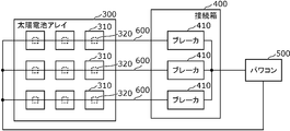
- FIG. 6 is a diagram for explaining an application example of the arc detection device according to the present invention.
- the arc detection device is applied to, for example, each component in a system in which DC power supplied from a solar panel 310 via wiring is converted into AC power by a power conditioner 500.
- a plurality (for example, three) of solar panels 310 connected in series by one wiring 600 (string) are arranged side by side to form a solar cell array 300.
- the plurality of wirings 600 are grouped by the junction box 400 and connected to the power conditioner 500.
- the DC power supply is the solar panel 310
- the first wiring is the wiring 600 connected to the positive electrode of the solar panel 310
- the second wiring is the wiring 600 connected to the negative electrode of the solar panel 310.
- the wiring 600 is branched in the power conditioner 500.
- a breaker 410 is provided for each wiring 600, and here, a breaker 410 is provided in the junction box 400.
- the breaker 410 does not have to be provided in the junction box 400.
- the breaker 410 may be provided between the junction box 400 and the solar cell array 300, or may be provided between the junction box 400 and the power conditioner 500 without being provided for each wiring 600.
- the solar panel 310 has, for example, a solar panel accessory module 320 that converts a signal output from the solar panel 310.
- the solar panel accessory module 320 is, for example, a DC / DC converter that optimizes the amount of power generation for each solar panel 310.
- the solar panel 310 does not have to have the module attached to the solar panel 320.
- the breaker 410 may be provided with an arc detection device.
- the breaker 410 cuts off the current flowing through the wiring 600 when it is determined that an abnormality has occurred.
- the solar panel 310 or the module attached to the solar panel 320 may include an arc detection device.
- the solar panel 310 or the module attached to the solar panel 320 stops the output to the wiring 600 when it is determined that an arc has been generated.
- the junction box 400 may be provided with an arc detection device. When it is determined that an arc has been generated, the junction box 400 cuts off the current flowing through the wiring 600, for example, via a breaker 410 or the like.
- the arc detection device according to the present invention is not limited to these, and can be applied to all systems that require arc detection.
- the breaker 410 may be provided with an arc detection device, and when it is determined that an arc has been generated, the current flowing through the first wiring and the second wiring may be cut off.
- the solar panel 310 may include an arc detection device and generate electricity by sunlight.
- the solar panel accessory module 320 may include an arc detection device and convert the signal output from the solar panel 310.
- the junction box 400 may include an arc detection device and may connect the solar panel 310 and the power conditioner 500.
- the arc determination unit included in the arc detection device may be realized by software in a general-purpose computer such as a personal computer.
Landscapes
- Physics & Mathematics (AREA)
- General Physics & Mathematics (AREA)
- Engineering & Computer Science (AREA)
- Power Engineering (AREA)
- Testing Of Short-Circuits, Discontinuities, Leakage, Or Incorrect Line Connections (AREA)
- Photovoltaic Devices (AREA)
- Testing Relating To Insulation (AREA)
- Protection Of Static Devices (AREA)
- Inverter Devices (AREA)
Priority Applications (4)
| Application Number | Priority Date | Filing Date | Title |
|---|---|---|---|
| JP2022505982A JP7437812B2 (ja) | 2020-03-11 | 2021-03-03 | アーク検出装置、パワーコンディショナ、屋内配線システム、ブレーカ、太陽光パネル、太陽光パネル付属モジュール及び接続箱 |
| CN202180018875.2A CN115298555B (zh) | 2020-03-11 | 2021-03-03 | 电弧检测装置、功率调节器、室内布线系统、断路器、太阳能板、太阳能板附属模块以及连接箱 |
| EP21767285.6A EP4120495A4 (en) | 2020-03-11 | 2021-03-03 | ARC DETECTION DEVICE, POWER CONDITIONER, INTERIOR WIRING SYSTEM, CIRCUIT BREAKER, SOLAR PANEL, SOLAR PANEL CONNECTION MODULE AND JUNCTION BOX |
| US17/908,317 US11923670B2 (en) | 2020-03-11 | 2021-03-03 | ARC detection device, solar inverter, indoor wiring system, circuit breaker, solar panel, solar panel attachment module, and junction box |
Applications Claiming Priority (2)
| Application Number | Priority Date | Filing Date | Title |
|---|---|---|---|
| JP2020041701 | 2020-03-11 | ||
| JP2020-041701 | 2020-03-11 |
Publications (1)
| Publication Number | Publication Date |
|---|---|
| WO2021182259A1 true WO2021182259A1 (ja) | 2021-09-16 |
Family
ID=77671641
Family Applications (1)
| Application Number | Title | Priority Date | Filing Date |
|---|---|---|---|
| PCT/JP2021/008291 Ceased WO2021182259A1 (ja) | 2020-03-11 | 2021-03-03 | アーク検出装置、パワーコンディショナ、屋内配線システム、ブレーカ、太陽光パネル、太陽光パネル付属モジュール及び接続箱 |
Country Status (5)
| Country | Link |
|---|---|
| US (1) | US11923670B2 (https=) |
| EP (1) | EP4120495A4 (https=) |
| JP (1) | JP7437812B2 (https=) |
| CN (1) | CN115298555B (https=) |
| WO (1) | WO2021182259A1 (https=) |
Families Citing this family (3)
| Publication number | Priority date | Publication date | Assignee | Title |
|---|---|---|---|---|
| CN115176407B (zh) * | 2020-03-11 | 2026-04-10 | 松下知识产权经营株式会社 | 异常探测装置、异常探测方法、记录介质、室内布线系统、功率调节器、断路器、太阳能板、太阳能板附属模块以及连接箱 |
| US12088080B2 (en) * | 2020-03-11 | 2024-09-10 | Panasonic Intellectual Property Management Co., Ltd. | Arc detection device, solar inverter, indoor wiring system, breaker, solar panel, solar panel-attached module, and junction box |
| US20250344518A1 (en) * | 2024-05-02 | 2025-11-06 | JBB Advanced Technologies, LLC | Method for manufacturing a solar panel having a solar cell and integrated circuits on the same silicon wafer |
Citations (9)
| Publication number | Priority date | Publication date | Assignee | Title |
|---|---|---|---|---|
| JP2010231456A (ja) * | 2009-03-26 | 2010-10-14 | Panasonic Electric Works Co Ltd | 電源システム |
| JP2011007765A (ja) | 2009-05-28 | 2011-01-13 | Kyocera Corp | アーク検出手段とそれを用いた制御手段及び連絡手段 |
| WO2011040325A1 (ja) * | 2009-09-30 | 2011-04-07 | 東芝ライテック株式会社 | 直流電源給電システム |
| JP2011109901A (ja) * | 2009-11-19 | 2011-06-02 | Samsung Sdi Co Ltd | 電力管理システム及びこれを備える系統連係型電力保存システム |
| WO2011065375A1 (ja) * | 2009-11-25 | 2011-06-03 | シャープ株式会社 | 電力変換装置、発電システム、及び充放電制御方法 |
| JP2017161240A (ja) * | 2016-03-07 | 2017-09-14 | オムロン株式会社 | アーク検出装置 |
| WO2017154274A1 (ja) * | 2016-03-07 | 2017-09-14 | オムロン株式会社 | アーク検出装置 |
| US20180191145A1 (en) * | 2016-08-19 | 2018-07-05 | Gd Midea Air-Conditioning Equipment Co., Ltd. | Household appliance and apparatus and method for detecting arc fault in the same |
| JP2019184480A (ja) * | 2018-04-13 | 2019-10-24 | 日東工業株式会社 | 放電検出構造及び放電検出システム |
Family Cites Families (15)
| Publication number | Priority date | Publication date | Assignee | Title |
|---|---|---|---|---|
| JPS5997812U (ja) | 1982-12-21 | 1984-07-03 | 三菱マテリアル株式会社 | 穴明け加工用工具 |
| JP2008042999A (ja) | 2006-08-02 | 2008-02-21 | Matsushita Electric Works Ltd | 電源供給装置 |
| JP2011010991A (ja) * | 2009-07-06 | 2011-01-20 | Sharp Corp | 空気清浄機 |
| SI23360A (sl) | 2010-04-07 | 2011-10-28 | Eti Elektroelement D.D. | Obločno ločilno stikalo |
| JP6000193B2 (ja) | 2013-06-14 | 2016-09-28 | 三菱電機株式会社 | Dcアーク検知装置 |
| JP6299507B2 (ja) * | 2014-07-29 | 2018-03-28 | オムロン株式会社 | 太陽光発電システムの保護装置および太陽光発電システムの保護方法 |
| US10348094B2 (en) | 2015-01-28 | 2019-07-09 | Abb Schweiz Ag | Energy panel arrangement shutdown |
| CN107041162B (zh) | 2015-04-22 | 2019-05-14 | 株式会社村田制作所 | 能量管理系统 |
| US11277000B2 (en) | 2016-06-21 | 2022-03-15 | Mitsubishi Electric Corporation | DC electrical circuit protection apparatus and ARC detection method |
| JP6673237B2 (ja) * | 2017-01-23 | 2020-03-25 | オムロン株式会社 | アーク検出装置 |
| JP2019158673A (ja) * | 2018-03-14 | 2019-09-19 | オムロン株式会社 | アーク検出装置およびその制御方法、並びに制御プログラム |
| US11209499B2 (en) | 2018-04-13 | 2021-12-28 | Nitto Kogyo Corporation | Distribution board |
| JP7108859B2 (ja) | 2018-04-25 | 2022-07-29 | パナソニックIpマネジメント株式会社 | アーク検出回路、ブレーカ、パワーコンディショナ、太陽光パネル、太陽光パネル付属モジュールおよび接続箱 |
| CN109378967B (zh) * | 2018-12-10 | 2023-11-10 | 刘秀清 | 基于直流反向倍压器的限流器电路和电池双向去极化电路 |
| WO2021182263A1 (ja) * | 2020-03-11 | 2021-09-16 | パナソニックIpマネジメント株式会社 | アーク検出装置、パワーコンディショナ、屋内配線システム、ブレーカ、太陽光パネル、太陽光パネル付属モジュール及び接続箱 |
-
2021
- 2021-03-03 US US17/908,317 patent/US11923670B2/en active Active
- 2021-03-03 WO PCT/JP2021/008291 patent/WO2021182259A1/ja not_active Ceased
- 2021-03-03 EP EP21767285.6A patent/EP4120495A4/en active Pending
- 2021-03-03 JP JP2022505982A patent/JP7437812B2/ja active Active
- 2021-03-03 CN CN202180018875.2A patent/CN115298555B/zh active Active
Patent Citations (9)
| Publication number | Priority date | Publication date | Assignee | Title |
|---|---|---|---|---|
| JP2010231456A (ja) * | 2009-03-26 | 2010-10-14 | Panasonic Electric Works Co Ltd | 電源システム |
| JP2011007765A (ja) | 2009-05-28 | 2011-01-13 | Kyocera Corp | アーク検出手段とそれを用いた制御手段及び連絡手段 |
| WO2011040325A1 (ja) * | 2009-09-30 | 2011-04-07 | 東芝ライテック株式会社 | 直流電源給電システム |
| JP2011109901A (ja) * | 2009-11-19 | 2011-06-02 | Samsung Sdi Co Ltd | 電力管理システム及びこれを備える系統連係型電力保存システム |
| WO2011065375A1 (ja) * | 2009-11-25 | 2011-06-03 | シャープ株式会社 | 電力変換装置、発電システム、及び充放電制御方法 |
| JP2017161240A (ja) * | 2016-03-07 | 2017-09-14 | オムロン株式会社 | アーク検出装置 |
| WO2017154274A1 (ja) * | 2016-03-07 | 2017-09-14 | オムロン株式会社 | アーク検出装置 |
| US20180191145A1 (en) * | 2016-08-19 | 2018-07-05 | Gd Midea Air-Conditioning Equipment Co., Ltd. | Household appliance and apparatus and method for detecting arc fault in the same |
| JP2019184480A (ja) * | 2018-04-13 | 2019-10-24 | 日東工業株式会社 | 放電検出構造及び放電検出システム |
Also Published As
| Publication number | Publication date |
|---|---|
| CN115298555B (zh) | 2025-08-19 |
| JP7437812B2 (ja) | 2024-02-26 |
| EP4120495A1 (en) | 2023-01-18 |
| US20230095385A1 (en) | 2023-03-30 |
| CN115298555A (zh) | 2022-11-04 |
| JPWO2021182259A1 (https=) | 2021-09-16 |
| US11923670B2 (en) | 2024-03-05 |
| EP4120495A4 (en) | 2023-09-13 |
Similar Documents
| Publication | Publication Date | Title |
|---|---|---|
| WO2021182263A1 (ja) | アーク検出装置、パワーコンディショナ、屋内配線システム、ブレーカ、太陽光パネル、太陽光パネル付属モジュール及び接続箱 | |
| JP7437812B2 (ja) | アーク検出装置、パワーコンディショナ、屋内配線システム、ブレーカ、太陽光パネル、太陽光パネル付属モジュール及び接続箱 | |
| KR101090263B1 (ko) | 태양광발전 시스템의 직류 전선로 지락 검출회로장치 및 지락 검출방법 | |
| CN109600115B (zh) | 在串联型的光伏发电系统中定位故障的方法 | |
| JP6037071B1 (ja) | アーク検出装置 | |
| AU2010347924A1 (en) | Photovoltaic power generation system | |
| JP2020139925A (ja) | アーク検出装置、ブレーカ、パワーコンディショナ、太陽光パネル、太陽光パネル付属モジュールおよび接続箱 | |
| CN115176407B (zh) | 异常探测装置、异常探测方法、记录介质、室内布线系统、功率调节器、断路器、太阳能板、太阳能板附属模块以及连接箱 | |
| JP6673237B2 (ja) | アーク検出装置 | |
| WO2019208027A1 (ja) | アーク検出回路、ブレーカ、パワーコンディショナ、太陽光パネル、太陽光パネル付属モジュールおよび接続箱 | |
| JP5745096B2 (ja) | 故障検出装置及びその検出方法 | |
| JP7357228B2 (ja) | アーク検出装置、パワーコンディショナ、屋内配線システム、ブレーカ、太陽光パネル、太陽光パネル付属モジュール及び接続箱 | |
| JP6103095B1 (ja) | アーク検出装置 | |
| JP7304532B2 (ja) | アーク検出装置、屋内電力線システム、太陽光発電システム及び蓄電池システム | |
| JP2021063663A (ja) | アーク検出装置、ブレーカ、パワーコンディショナ、太陽光パネル、太陽光パネル付属モジュール、接続箱、アーク検出システム及びアーク検出方法 | |
| JP2022150120A (ja) | 太陽光発電システムおよび太陽光発電システムの地絡検知方法 | |
| CN218829853U (zh) | 一种光伏阵列及光伏发电系统 | |
| KR20250099012A (ko) | 전력변환장치 |
Legal Events
| Date | Code | Title | Description |
|---|---|---|---|
| 121 | Ep: the epo has been informed by wipo that ep was designated in this application |
Ref document number: 21767285 Country of ref document: EP Kind code of ref document: A1 |
|
| ENP | Entry into the national phase |
Ref document number: 2022505982 Country of ref document: JP Kind code of ref document: A |
|
| NENP | Non-entry into the national phase |
Ref country code: DE |
|
| ENP | Entry into the national phase |
Ref document number: 2021767285 Country of ref document: EP Effective date: 20221011 |
|
| WWG | Wipo information: grant in national office |
Ref document number: 202180018875.2 Country of ref document: CN |