WO2021182239A1 - 物体認識装置 - Google Patents
物体認識装置 Download PDFInfo
- Publication number
- WO2021182239A1 WO2021182239A1 PCT/JP2021/008187 JP2021008187W WO2021182239A1 WO 2021182239 A1 WO2021182239 A1 WO 2021182239A1 JP 2021008187 W JP2021008187 W JP 2021008187W WO 2021182239 A1 WO2021182239 A1 WO 2021182239A1
- Authority
- WO
- WIPO (PCT)
- Prior art keywords
- pseudo
- length
- interest
- unit
- shielded
- Prior art date
- Legal status (The legal status is an assumption and is not a legal conclusion. Google has not performed a legal analysis and makes no representation as to the accuracy of the status listed.)
- Ceased
Links
Images



Classifications
-
- G—PHYSICS
- G01—MEASURING; TESTING
- G01S—RADIO DIRECTION-FINDING; RADIO NAVIGATION; DETERMINING DISTANCE OR VELOCITY BY USE OF RADIO WAVES; LOCATING OR PRESENCE-DETECTING BY USE OF THE REFLECTION OR RERADIATION OF RADIO WAVES; ANALOGOUS ARRANGEMENTS USING OTHER WAVES
- G01S17/00—Systems using the reflection or reradiation of electromagnetic waves other than radio waves, e.g. lidar systems
- G01S17/88—Lidar systems specially adapted for specific applications
- G01S17/93—Lidar systems specially adapted for specific applications for anti-collision purposes
- G01S17/931—Lidar systems specially adapted for specific applications for anti-collision purposes of land vehicles
-
- G—PHYSICS
- G01—MEASURING; TESTING
- G01S—RADIO DIRECTION-FINDING; RADIO NAVIGATION; DETERMINING DISTANCE OR VELOCITY BY USE OF RADIO WAVES; LOCATING OR PRESENCE-DETECTING BY USE OF THE REFLECTION OR RERADIATION OF RADIO WAVES; ANALOGOUS ARRANGEMENTS USING OTHER WAVES
- G01S17/00—Systems using the reflection or reradiation of electromagnetic waves other than radio waves, e.g. lidar systems
- G01S17/88—Lidar systems specially adapted for specific applications
- G01S17/89—Lidar systems specially adapted for specific applications for mapping or imaging
-
- G—PHYSICS
- G01—MEASURING; TESTING
- G01S—RADIO DIRECTION-FINDING; RADIO NAVIGATION; DETERMINING DISTANCE OR VELOCITY BY USE OF RADIO WAVES; LOCATING OR PRESENCE-DETECTING BY USE OF THE REFLECTION OR RERADIATION OF RADIO WAVES; ANALOGOUS ARRANGEMENTS USING OTHER WAVES
- G01S7/00—Details of systems according to groups G01S13/00, G01S15/00, G01S17/00
- G01S7/48—Details of systems according to groups G01S13/00, G01S15/00, G01S17/00 of systems according to group G01S17/00
- G01S7/4802—Details of systems according to groups G01S13/00, G01S15/00, G01S17/00 of systems according to group G01S17/00 using analysis of echo signal for target characterisation; Target signature; Target cross-section
Definitions
- This disclosure relates to an object recognition device.
- An object recognition device that is mounted on a vehicle and recognizes an object based on the reflected wave of the irradiated electromagnetic wave is known.
- erroneous recognition of an object due to a multipath phenomenon may occur. For example, if the irradiated electromagnetic wave is reflected by the side surface of the object, then reflected by another object, and then received as a reflected wave, it is erroneously recognized that the object exists in the irradiation direction of the electromagnetic wave in which the object does not actually exist. Will be done.
- the side surface of the shielded object which is an object in which the electromagnetic wave emitted in the direction in which the object is located exists in front of the object.
- a method of determining whether or not another object exists in the reflection direction is conceivable.
- the length of the side surface of the shielded object may not be appropriately detected depending on the positional relationship between the shielded object and the vehicle equipped with the object recognition device. It has been found that it may not be possible to properly determine whether the object is a misrecognized object due to the multi-pass phenomenon.
- One aspect of the present disclosure is object recognition, in which it is possible to determine whether a recognized object is a misrecognized object due to a multipath phenomenon, even if the length of the side surface of the shielded object cannot be appropriately detected. Provide the device.
- One aspect of the present disclosure is an object recognition device, which includes a recognition unit and an object determination unit.
- the recognition unit is configured to recognize an object by irradiating a transmission wave in a plurality of irradiation directions and receiving a reflected wave of the transmission wave.
- the object determination unit is a pseudo-object in which the object of interest, which is one of the objects recognized by the recognition unit, is erroneously recognized by reflecting the transmitted wave on the side surface of the shielded object, which is an object existing in front of the object of interest. Is configured to determine.
- the object determination unit includes a detection unit, a guessing unit, and a pseudo determination unit. The detection unit is configured to detect the width of the shielded object.
- the guessing unit is configured to estimate the length of the side surface of the shielded object based on the width of the shielded object detected by the detecting unit, assuming that the shielded object is a vehicle.
- the pseudo-determination unit is configured to determine whether the object of interest is a pseudo-object by using the length of the side surface of the shielded object estimated by the estimation unit. In addition, the pseudo-determination unit determines that the transmitted wave emitted in the direction in which the object of interest is located is reflected on the side surface of the shielded object, and the reflection direction is the same as the distance from the reflection position to the object of interest. It is configured to determine that the object of interest is a pseudo-object when another object is recognized at a position distant from.
- FIG. 1 is a block diagram showing a configuration of a rider device.
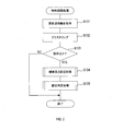
- FIG. 2 is a flowchart of the object recognition process.
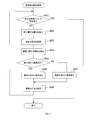
- FIG. 3 is a flowchart of the side length setting process in the object recognition process.
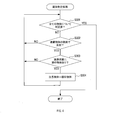
- FIG. 4 is a flowchart of a pseudo determination process in the object recognition process.
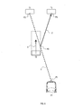
- FIG. 5 is a schematic view showing an example in which the own vehicle and the object recognized by the object recognition process are viewed from above.
- FIG. 6 is a schematic view showing another example in which the own vehicle and the object recognized by the object recognition process are viewed from above.
- FIG. 7 is a schematic view showing still another example in which the own vehicle and the object recognized by the object recognition process are viewed from above.
- the rider device 1 shown in FIG. 1 is an object recognition device that recognizes an object by irradiating a laser beam and receiving the reflected light.
- the rider device 1 is used, for example, mounted on a vehicle and is used for recognizing various objects existing around the vehicle.
- the vehicle equipped with the rider device 1 is also referred to as an own vehicle.
- the lidar is also referred to as lidar.
- LIDAR is an abbreviation for Light Detection and Ranging.
- the rider device 1 includes an irradiation unit 10, a light receiving unit 20, and a control unit 30.
- the irradiation unit 10 irradiates a predetermined irradiation region with a laser beam based on an instruction from the control unit 30.
- the irradiation area is an area in front of the vehicle that extends in a predetermined angle range in each of the horizontal direction and the vertical direction.
- the irradiation unit 10 irradiates the entire irradiation region with the laser beam by irradiating each irradiation division in which the irradiation region is divided into a plurality of regions in the horizontal direction and the vertical direction.
- the light receiving unit 20 receives the reflected light of the laser light emitted by the irradiation unit 10. Further, the light receiving unit 20 converts the received reflected light into an electric signal and outputs it to the control unit 30.
- the control unit 30 is mainly composed of a well-known microcomputer having a CPU 31, a RAM 32, a ROM 33, and a flash memory 34.
- the function of the control unit 30 is realized by the CPU 31 executing a program stored in a non-transitional substantive recording medium.
- ROM 33 corresponds to a non-transitional substantive recording medium.
- the control unit 30 may include one microcomputer or a plurality of microcomputers.
- the CPU 31 starts the object recognition process when the scanning of the laser beam for one cycle is completed.
- the completion of scanning the laser beam for one cycle means that the irradiation of the laser beam by the irradiation unit 10 is completed in the entire irradiation region.
- the reflection point information includes information indicating a reflection point which is a point where the laser light is reflected, for example, information indicating the irradiation direction of the laser light related to the reflection point and the distance from the lidar device 1 to the reflection point.
- the CPU 31 acquires reflection point information for all reflection points obtained by scanning one cycle of laser light.
- the CPU 31 forms a cluster point cloud by performing clustering for all the reflection points based on the reflection point information acquired in S101, and recognizes the formed cluster point group as an object.
- the CPU 31 determines whether or not there are three or more objects recognized in S102.
- the CPU 31 determines in S103 that the number of objects recognized in S102 is not three or more, that is, when it determines that the number of recognized objects is two or less, the CPU 31 ends the object recognition process.
- the side surface length setting process means a process of setting the side surface length for each object recognized in S102, as will be described in detail later.
- the CPU 31 executes a pseudo determination process.
- the pseudo determination process refers to a process of determining whether each object recognized in S102 is a pseudo object due to a multipath phenomenon.
- the pseudo-object due to the multipath phenomenon refers to an object erroneously recognized in S102 due to the reflection of the laser beam on the side surface of another object located closer to the rider device 1.
- the CPU 31 ends the object recognition process when S105 ends.
- the CPU 31 performs the processes from S202 to S208 described later for all the objects recognized in S102, and determines whether or not the length of the side surface is set.
- the CPU 31 determines in S201 that the side lengths have been set for all the objects, the CPU 31 ends the side length setting process.
- the CPU 31 selects one of the plurality of objects recognized in S102 whose side length has not yet been set as the target object. Then, the CPU 31 detects information about the width of the target object based on the reflection points belonging to the cluster point group of the target object. Specifically, in the present embodiment, the CPU 31 detects the width of the target object, that is, the length in the width direction of the target object as information regarding the width of the target object.
- the CPU 31 may adopt, for example, the following values (a)-(c) as the detection value of the width of the target object. (A) The width of the target object detected from the scanning results for one cycle, the so-called instantaneous value.
- (B) An average value obtained by averaging the widths of the target objects detected from each of the scanning results for a plurality of cycles.
- (C) The maximum value of the width of the target object detected from each of the scanning results for a plurality of cycles.
- the CPU 31 adopts the average value of the above (b) as the detection value of the width of the target object.
- the CPU 31 estimates the length of the side surface of the target object when it is assumed that the target object is a vehicle, based on the width of the target object detected in S202.
- the CPU 31 estimates the length of the side surface of the target object by collating the width of the target object detected in S202 with the table stored in advance in the flash memory 34.
- the table stored in advance in the flash memory 34 is a table showing the relationship between the vehicle width and the vehicle length.
- the approximate width and length of the vehicle are determined for each vehicle category.
- the vehicle width is about 1.4 m and the vehicle length is about 3.4 m.
- the vehicle width is about 1.8 m and the vehicle length is about 4.8 m.
- the vehicle width is about 2.5 m and the vehicle length is about 10 m.
- the flash memory 34 for example, when the vehicle width is less than 1.5 m, 1.5 m or more and less than 2.1 m, and 2.1 m or more, the corresponding vehicle lengths are 3.4 m, 4.8 m, and 4.8 m, respectively.
- a table showing the relationship between the vehicle width and the vehicle length, such as 10 m, is stored.
- the CPU 31 estimates the length of the side surface of the target object corresponding to the vehicle length by collating the above table with the width of the target object detected in S202.
- the length of the side surface of the target object estimated in S203 is also referred to as an estimated length.
- the CPU 31 detects information about the side surface of the target object based on the reflection points belonging to the cluster point cloud of the target object. Specifically, in the present embodiment, the CPU 31 detects the length of the side surface of the target object as information regarding the side surface of the target object.
- the length of the side surface of the target object can be detected appropriately depends on the positional relationship between the target object and the own vehicle. For example, when the target object is located diagonally in front of the own vehicle, the laser beam is easily reflected by the side surface of the target object, so that the length of the side surface of the target object can be appropriately detected. On the other hand, for example, when the target object is located in front of the own vehicle, it is difficult to properly detect the length of the side surface of the target object because the laser beam is less likely to be reflected by the side surface of the target object. .. Since there are cases where the length of the side surface of the target object can be appropriately detected and cases where it is difficult to detect it appropriately, the length of the side surface of the target object may vary in the detected value.
- the scanning results for a plurality of cycles are traced back, and the maximum value of the side lengths of the target object detected from each is adopted as the detection value of the side lengths of the target object.
- the maximum value the pseudo-judgment process described in detail later is executed under the condition that the multipath phenomenon is more likely to occur, and the erroneous recognition of the object due to the multipath phenomenon is less likely to be overlooked. This is because the multipath phenomenon may occur when the irradiated laser beam is reflected by the side surface of the target object, but it is considered that the longer the side surface of the target object, the higher the possibility of reflecting the irradiated laser beam. be.
- the length of the side surface of the target object detected in S204 is also referred to as the detection length.
- the CPU 31 determines whether the detection length is larger than the estimated length.
- the CPU 31 determines in S205 that the detection length is larger than the estimated length, the CPU 31 shifts to S206 and sets the detection length as the length of the side surface of the target object.
- the CPU 31 determines in S205 that the detected length is not larger than the estimated length, that is, the detected length is equal to or less than the estimated length, the CPU 31 shifts to S207 and estimates it as the length of the side surface of the target object. Set the length.
- the CPU 31 estimates the direction of the side surface of the target object. Specifically, in the present embodiment, the CPU 31 estimates that the moving direction of the target object, that is, the traveling direction of the target object when the target object is a vehicle, is the direction of the side surface of the target object. The moving direction of the target object is calculated from the change over time in the position of the target object with respect to the own vehicle.
- 5 to 7 are schematic views illustrating the positions of the own vehicle and each recognized object in the top view when three objects are recognized in S102.
- the own vehicle is represented by the vehicle V1
- the three recognized objects are represented by the object T1, the object T2, and the object T3, respectively.
- each object is indicated by a solid rectangle.
- the pseudo-judgment process is a process for determining whether the recognized object is a pseudo-object due to the multipath phenomenon. This determination is performed on a two-dimensional plane on which the own vehicle and the recognized object are projected in a top view.
- the CPU 31 performs the processes from S302 to S304 described later for all the objects recognized in S102, and determines whether or not the determination of whether the object is a pseudo object by the multipath phenomenon is completed.
- the CPU 31 determines in S301 that all the objects have been determined to be pseudo-objects, the CPU 31 ends the pseudo-determination process.
- the CPU 31 selects one of the plurality of objects recognized in S102, which has not yet been determined to be a pseudo object, as the object of interest. Then, the CPU 31 determines whether the laser beam emitted in the direction in which the object of interest is located is reflected by the side surface of the other object.
- the CPU 31 first determines whether or not another object exists between the object of interest and the own vehicle. In the examples shown in FIGS. 5 to 7, for example, when the object T1 is selected as the object of interest, it is determined that the object T2 exists between the vehicle V1 and the object T1.
- another object determined to exist between the object of interest and the own vehicle is also referred to as a shielding object.
- the CPU 31 sets the shielded object for the shielded object by the side length setting process on the two-dimensional plane on which the own vehicle and the recognized object are projected in the top view. It is determined whether the side surface of the shielded object on the own vehicle side intersects with the straight line connecting the object of interest and the own vehicle, assuming that the object has a rectangular shape having a length and a side surface in the estimated orientation.
- the straight line connecting the object of interest and the own vehicle refers to a straight line connecting one point in the object of interest and a predetermined reference point in the rider device 1 mounted on the own vehicle.
- the point P3 is one point on the object T1.
- the point P1 is a reference point of the rider device 1 mounted on the vehicle V1. That is, the broken line Y connecting the points P1 and P3 corresponds to the straight line. Further, the arrow X in FIGS. 5 to 7 is the traveling direction of the object T2, and the broken line rectangle is the shape assumed for the object T2.
- One point in the object of interest may be, for example, one of a plurality of reflection points belonging to the cluster point group recognized as the object of interest, or the center of some reflection points selected from the plurality of reflection points. It may be a point or the center point of all reflection points. Further, the CPU 31 may determine whether the straight line connecting the attention object and the own vehicle intersects the side surface of the shielding object on the own vehicle side based on only one point in the attention object, or a plurality of in the attention object. It may be determined whether each straight line connecting each of the points and the own vehicle intersects the side surface of the shielding object on the own vehicle side.
- the CPU 31 may determine that it intersects the side surface of the shielding object on the own vehicle side, or may determine in advance. When the number or more intersects the side surface of the shield object on the own vehicle side, it may be determined that the shield object intersects the side surface of the shield object on the own vehicle side.
- the CPU 31 determines that the straight line connecting the object of interest and the own vehicle intersects the side surface of the shielding object on the own vehicle side, the laser beam emitted in the direction in which the object of interest is located is reflected by the side surface of the shielding object.
- the CPU 31 determines in S302 that the laser beam emitted in the direction in which the object of interest is located is reflected by the side surface of the shielded object, the CPU 31 shifts to S303.
- the CPU 31 determines whether an object other than the shielding object exists at the real image position.
- the real image position is a position separated from the reflection position on the side surface of the shielded object in the reflection direction by the same distance as the distance from the reflection position to the object of interest.
- the reflection position on the side surface of the shielded object is the reflection position of the laser beam on the side surface of the shielded object determined in S302 to reflect the laser beam emitted in the direction in which the object of interest is located.
- the point P2 corresponds to the reflection position.
- the reflection direction is a direction in which the laser beam reflected at the reflection position travels straight.
- the direction indicated by the arrow Z corresponds to the reflection direction.
- the point P4 corresponds to the real image position. That is, in FIGS. 5 to 7, points P2 to P3 and points P2 to P4 have the same length.
- the CPU 31 makes a real image of the object related to the cluster point cloud. It may be determined that the object exists at the position. In the examples shown in FIGS. 5 and 6, since the object T3 exists at the point P4, it is determined that an object different from the shielding object exists at the real image position. In the example shown in FIG. 7, since the object does not exist at the point P4, it is determined that the object does not exist at the real image position.
- the CPU 31 determines that the object of interest is a pseudo-object due to the multipath phenomenon, and invalidates the recognition of the object of interest. In the examples shown in FIGS. 5 and 6, recognition of the object T1 is invalidated.
- the CPU 31 returns the process to S301 when S304 shown in FIG. 4 is completed.
- the rider device 1 is configured to estimate the length of the side surface of the shielded object based on the width of the shielded object, assuming that the shielded object is a vehicle. Further, the rider device 1 is configured to determine whether or not the object of interest is a pseudo object by using the estimated length of the side surface of the shielding object. The rider device 1 determines that the laser beam emitted in the direction in which the object of interest is located is reflected on the side surface of the shielding object, and is separated from the reflection position in the reflection direction by the same distance as the distance from the reflection position to the object of interest. When another object is recognized at the position, it is determined that the object of interest is a pseudo object.
- the rider device 1 is further configured to estimate the orientation of the side surface of the shielded object. Further, the rider device 1 is configured to determine whether or not the object of interest is a pseudo object by using the estimated length and orientation of the side surface of the shielding object.
- the reflection direction of the laser beam can be estimated more appropriately. Therefore, it is possible to more appropriately determine whether the recognized object is an object erroneously recognized due to the multipath phenomenon.
- the rider device 1 is further configured to estimate the traveling direction of the shielding object as the direction of the side surface of the target object. Further, the rider device 1 is configured to determine whether or not the object of interest is a pseudo object by using the estimated length and orientation of the side surface of the shielding object.
- the reflection direction of the laser beam can be estimated more appropriately. Therefore, it is possible to more appropriately determine whether the recognized object is an object erroneously recognized due to the multipath phenomenon.
- the rider device 1 is further configured to detect the length of the side surface of the shielded object. Further, the rider device 1 is configured to determine whether the object of interest is a pseudo object by using either the detected side length of the shield object or the estimated side length of the shield object. Will be done.
- the CPU 31 determines the length of the side surface of the target object as information on the side surface of the target object based on the reflection points belonging to the cluster point group of the target object. It is being detected. However, the CPU 31 may further detect the length direction of the side surface of the target object as information regarding the side surface of the target object. When the length direction of the side surface of the target object is detected as the information about the side surface of the target object, the CPU 31 sets the length direction of the side surface of the detected target object as the side surface of the target object in S208 in the side surface length setting process. You may guess the direction of. By adopting such an estimation method, it is possible to estimate the direction of the side surface of the target object, for example, when the target object is a stationary object, specifically, even when the target object is a roadside object such as a side wall.
- the CPU 31 detects the width of the target object as information regarding the width of the target object based on the reflection points belonging to the cluster point group of the target object. There is. However, the CPU 31 may further detect the width direction of the target object as information regarding the width of the target object.
- the CPU 31 sets the direction perpendicular to the detected width direction of the target object as the direction of the side surface of the target object. You may guess. If such an estimation method is adopted, the orientation of the side surface can be estimated even when the target object is a stationary object, for example. Further, for example, even when it is difficult to appropriately detect the length direction of the side surface of the target object for the same reason as when it is difficult to appropriately detect the length of the side surface of the target object described above, the target object The orientation of the sides can be inferred.
- the CPU 31 traces back the scanning results for a plurality of cycles as the detection value of the side surface length of the target object, and detects the target object from each of them.
- the maximum value of the side length is adopted.
- the CPU 31 may adopt, for example, the length of the side surface of the target object detected from the scanning result for one cycle, that is, the so-called instantaneous value, as the detected value of the side length of the target object.
- the CPU 31 may adopt, for example, an average value obtained by averaging the side lengths of the target object detected from each of the scanning results for a plurality of cycles as the detected value of the side length of the target object.
- the CPU 31 adopts a larger length of the estimated length and the detected length as the setting value of the side surface length of the target object. doing.
- the CPU 31 may adopt, for example, a smaller length as the setting value of the length of the side surface of the target object. If a smaller length is adopted, it is possible to prevent the recognized object from being erroneously determined to be a pseudo object due to the multipath phenomenon.
- the CPU 31 estimates the side surface length and orientation of each recognized object.
- the CPU 31 does not have to estimate the side length and orientation of all the recognized objects in the side length setting process.
- the CPU 31 may estimate the length and orientation of the side surface only for, for example, another object determined to exist between the object of interest and the own vehicle, that is, a shielding object.
- the CPU 31 when the pseudo determination process is completed, the CPU 31 ends the object recognition process, but for example, the pseudo determination process is performed again using the orientation of the side surface estimated by a different method. You may go. Further, the CPU 31 may perform the pseudo determination process repeatedly, for example, three times or more. Specifically, for example, as the orientation of the side surface estimated for the shielded object, the first time is the moving direction of the shielded object, the second time is the length direction of the side surface of the shielded object, and the third time is perpendicular to the width direction of the shielded object. The CPU 31 may repeatedly perform the pseudo determination process by adopting the respective directions.
- the CPU 31 determines that the object is a pseudo object. May be good. If such a determination method is adopted, it becomes difficult for a pseudo object due to the multipath phenomenon to be overlooked. Further, in the pseudo determination process performed a plurality of times, when it is determined that the same object is a pseudo object due to the multipath phenomenon more than a predetermined number of times, for example, twice or more, the CPU 31 determines that the object is a pseudo object. It may be determined that there is. By adopting such a determination method, it is possible to prevent the recognized object from being erroneously determined to be a pseudo object due to the multipath phenomenon.
- the functions of one component in the above embodiment may be dispersed as a plurality of components, or the functions of the plurality of components may be integrated into one component. Further, a part of the configuration of the above embodiment may be omitted. Further, at least a part of the configuration of the above embodiment may be added or replaced with the configuration of the other embodiment.
- S101 to S102 correspond to the processing as the recognition unit
- S104 to S105 correspond to the processing as the object determination unit.
Landscapes
- Engineering & Computer Science (AREA)
- Physics & Mathematics (AREA)
- Computer Networks & Wireless Communication (AREA)
- General Physics & Mathematics (AREA)
- Radar, Positioning & Navigation (AREA)
- Remote Sensing (AREA)
- Electromagnetism (AREA)
- Optical Radar Systems And Details Thereof (AREA)
Abstract
物体認識装置は、認識部と、物体判定部と、を備える。物体判定部は、検出部と、推測部と、疑似判定部と、を備える。推測部は、遮蔽物体(T2)が車両であると仮定し、検出部により検出された遮蔽物体(T2)の幅に基づいて遮蔽物体(T2)の側面の長さを推測するように構成される。疑似判定部は、推測部により推測された遮蔽物体(T2)の側面の長さを用いて、注目物体(T1)が疑似物体であるかを判定するように構成されるものであって、注目物体(T1)が位置する方向へ照射された送信波が遮蔽物体(T2)の側面で反射されたと判定され、かつ、反射位置(P2)から注目物体(T1)までの距離と同じ距離(Z)だけ反射位置(P2)から反射方向へ離れた位置(P4)に別の物体(T3)が認識されている場合に、注目物体(T1)が疑似物体であると判定するように構成される。
Description
本国際出願は、2020年3月10日に日本国特許庁に出願された日本国特許出願第2020-41095号に基づく優先権を主張するものであり、日本国特許出願第2020-41095号の全内容を本国際出願に参照により援用する。
本開示は、物体認識装置に関する。
車両に搭載され、照射した電磁波の反射波に基づいて物体を認識する物体認識装置が知られている。
この種の物体認識装置では、例えば特許文献1に記載のように、マルチパス現象による物体の誤認識が生じる場合がある。例えば、照射された電磁波が物体の側面で反射されたのち別の物体にも反射されてから反射波として受信された場合、実際には物体が存在しない電磁波の照射方向に物体が存在すると誤認識されてしまう。
認識された物体がマルチパス現象により誤認識された物体であるかを判定するためには、当該物体が位置する方向へ照射された電磁波が当該物体の手前に存在する物体である遮蔽物体の側面で反射され、かつ、その反射方向に別の物体が存在するかを判定する手法が考えられる。しかしながら、発明者の詳細な検討の結果、遮蔽物体の側面の長さは遮蔽物体と物体認識装置を搭載した車両との位置関係等によって適切に検出されない場合があるため、上述した判定手法では認識された物体がマルチパス現象により誤認識された物体であるかを適切に判定できない場合があるという課題が見出された。
本開示の一局面は、遮蔽物体の側面の長さを適切に検出することができなくても、認識された物体がマルチパス現象により誤認識された物体かを判定することができる、物体認識装置を提供する。
本開示の一態様は、物体認識装置であって、認識部と、物体判定部と、を備える。認識部は、複数の照射方向へ送信波を照射し、送信波の反射波を受信することにより、物体を認識するように構成される。物体判定部は、認識部により認識された物体の1つである注目物体が、注目物体よりも手前に存在する物体である遮蔽物体の側面で送信波が反射することにより誤認識された疑似物体であるかを判定するように構成される。また、物体判定部は、検出部と、推測部と、疑似判定部と、を備える。検出部は、遮蔽物体の幅を検出するように構成される。推測部は、遮蔽物体が車両であると仮定し、検出部により検出された遮蔽物体の幅に基づいて遮蔽物体の側面の長さを推測するように構成される。疑似判定部は、推測部により推測された遮蔽物体の側面の長さを用いて、注目物体が疑似物体であるかを判定するように構成される。また、疑似判定部は、注目物体が位置する方向へ照射された送信波が遮蔽物体の側面で反射されたと判定され、かつ、反射位置から注目物体までの距離と同じ距離だけ反射位置から反射方向へ離れた位置に別の物体が認識されている場合に、注目物体が疑似物体であると判定するように構成される。
このような構成によれば、遮蔽物体の側面の長さを適切に検出することができなくても、認識された物体がマルチパス現象により誤認識された物体かを判定することができる。
以下、本開示の例示的な実施形態について図面を参照しながら説明する。
[1.構成]
図1に示すライダ装置1は、レーザ光を照射してその反射光を受信することにより物体を認識する物体認識装置である。ライダ装置1は、例えば、車両に搭載して使用され、車両の周辺に存在する種々の物体の認識に用いられる。以下、ライダ装置1を搭載した車両を自車両ともいう。なお、ライダは、LIDARとも表記される。LIDARは、Light Detection and Rangingの略語である。
図1に示すライダ装置1は、レーザ光を照射してその反射光を受信することにより物体を認識する物体認識装置である。ライダ装置1は、例えば、車両に搭載して使用され、車両の周辺に存在する種々の物体の認識に用いられる。以下、ライダ装置1を搭載した車両を自車両ともいう。なお、ライダは、LIDARとも表記される。LIDARは、Light Detection and Rangingの略語である。
ライダ装置1は、図1に示すように、照射部10と、受光部20と、制御部30と、を備える。
照射部10は、制御部30からの指示に基づき、あらかじめ定められた照射領域にレーザ光を照射する。照射領域は、車両の前方における、水平方向及び垂直方向のそれぞれに所定の角度範囲で広がる領域である。照射部10は、照射領域を水平方向及び垂直方向のそれぞれについて複数に区分した各照射区分にレーザ光を照射することにより、照射領域の全域にレーザ光を照射する。
受光部20は、照射部10により照射されたレーザ光の反射光を受光する。また、受光部20は、受光した反射光を電気信号に変換して制御部30に出力する。
制御部30は、CPU31、RAM32、ROM33及びフラッシュメモリ34を有する周知のマイクロコンピュータを中心に構成される。制御部30の機能は、CPU31が非遷移的実体的記録媒体に格納されたプログラムを実行することにより実現される。この例では、ROM33が非遷移的実体的記録媒体に該当する。また、プログラムが実行されることにより、当該プログラムに対応する方法が実行される。なお、制御部30は、1つのマイクロコンピュータを備えてもよいし、複数のマイクロコンピュータを備えてもよい。
[2.処理]
次に、制御部30のCPU31が実行する物体認識処理について、図2に示すフローチャートを用いて説明する。CPU31は、1サイクル分のレーザ光の走査が終了したことを契機に物体認識処理を開始する。1サイクル分のレーザ光の走査が終了したこととは、照射部10によるレーザ光の照射が照射領域の全域において完了したことを指す。
次に、制御部30のCPU31が実行する物体認識処理について、図2に示すフローチャートを用いて説明する。CPU31は、1サイクル分のレーザ光の走査が終了したことを契機に物体認識処理を開始する。1サイクル分のレーザ光の走査が終了したこととは、照射部10によるレーザ光の照射が照射領域の全域において完了したことを指す。
まず、S101で、CPU31は、反射点情報を取得する。反射点情報には、レーザ光が反射された地点である反射点を示す情報、例えば反射点に係るレーザ光の照射方位やライダ装置1から反射点までの距離を示す情報が含まれる。S101で、CPU31は、1サイクル分のレーザ光の走査により得られた全ての反射点について、反射点情報を取得する。
続いて、S102で、CPU31は、S101で取得した反射点情報に基づいて全ての反射点についてクラスタリングを実行することによりクラスタ点群を形成し、形成されたクラスタ点群を物体として認識する。
続いて、S103で、CPU31は、S102で認識された物体が3つ以上かを判定する。CPU31は、S103で、S102で認識された物体が3つ以上でないと判定した場合、すなわち認識された物体が2つ以下であると判定した場合には、物体認識処理を終了する。
一方、CPU31は、S103で、S102で認識された物体が3つ以上であると判定した場合には、S104に移行し、側面長さ設定処理を実行する。側面長さ設定処理とは、後に詳述するとおり、S102で認識された各物体について側面の長さを設定する処理をいう。
続いて、S105で、CPU31は、疑似判定処理を実行する。疑似判定処理とは、後に詳述するとおり、S102で認識された各物体についてマルチパス現象による疑似物体かを判定する処理をいう。マルチパス現象による疑似物体とは、ライダ装置1からの距離がより近い位置に存在する他の物体の側面でレーザ光が反射することにより、S102で誤認識された物体を指す。
CPU31は、S105が終了すると、物体認識処理を終了する。
次に、物体認識処理のうちの側面長さ設定処理について、図3に示すフローチャートを用いて説明する。
まず、S201で、CPU31は、S102で認識された全ての物体について、後述するS202からS208までの処理を行い、側面の長さを設定したかを判定する。CPU31は、S201で全ての物体について側面の長さを設定したと判定した場合には、側面長さ設定処理を終了する。
一方、CPU31は、S201で全ての物体については側面の長さを設定していない、すなわち側面の長さがまだ設定されていない物体が存在すると判定した場合には、S202に移行する。
S202で、CPU31は、S102で認識された複数の物体のうち、側面の長さがまだ設定されていない物体の1つを対象物体として選択する。そして、CPU31は、対象物体のクラスタ点群に属する反射点に基づいて、対象物体の幅に関する情報を検出する。具体的には、本実施形態では、CPU31は、対象物体の幅に関する情報として対象物体の幅、すなわち対象物体の幅方向の長さを検出する。CPU31は、対象物体の幅の検出値として、例えば次の(a)-(c)のような値を採用してもよい。(a)1サイクル分の走査結果から検出される対象物体の幅、いわゆる瞬時値。(b)複数サイクル分の走査結果を遡ってそれぞれから検出される対象物体の幅を平均した平均値。(c)複数サイクル分の走査結果のそれぞれから検出される対象物体の幅のうちの最大値。本実施形態では、CPU31は、上記(b)の平均値を対象物体の幅の検出値として採用している。
続いて、S203で、CPU31は、S202で検出された対象物体の幅に基づき、対象物体が車両であると仮定した場合における対象物体の側面の長さを推測する。
具体的には、CPU31は、S202で検出された対象物体の幅とフラッシュメモリ34内にあらかじめ記憶されたテーブルとを照合することにより、対象物体の側面の長さを推測する。フラッシュメモリ34内にあらかじめ記憶されたテーブルとは、車幅と車長との関係を示すテーブルである。車両は、車両の区分ごとにおおよその車幅及び車長が定まる。例えば軽乗用車であれば、車幅は約1.4m、車長は約3.4mである。また、例えば普通乗用車であれば、車幅は約1.8m、車長は約4.8mである。また、例えばトラックであれば、車幅は約2.5m、車長は約10mである。そこで、フラッシュメモリ34には、例えば、車幅が1.5m未満、1.5m以上2.1m未満、及び2.1m以上のとき、対応する車長はそれぞれ3.4m、4.8m、及び10mというように、車幅と車長との関係を示すテーブルが記憶されている。CPU31は、対象物体が車両であると仮定して、上記テーブルとS202で検出された対象物体の幅とを照合することにより、車長に相当する対象物体の側面の長さを推測する。以下、S203で推測された対象物体の側面の長さを推測長さともいう。
続いて、S204で、CPU31は、対象物体のクラスタ点群に属する反射点に基づいて、対象物体の側面に関する情報を検出する。具体的には、本実施形態では、CPU31は、対象物体の側面に関する情報として、対象物体の側面の長さを検出する。
対象物体の側面の長さを適切に検出できるかは、対象物体と自車両との位置関係等によって異なる。例えば対象物体が自車両の斜め前方に位置する場合は、対象物体の側面によってレーザ光が反射されやすいため、対象物体の側面の長さを適切に検出することができる。これに対して、例えば対象物体が自車両の正面に位置する場合は、対象物体の側面によってレーザ光が反射されることが少ないため、対象物体の側面の長さを適切に検出することが難しい。このように対象物体の側面の長さを適切に検出することができる場合と適切に検出することが難しい場合とがあるため、対象物体の側面の長さは検出値にばらつきが生じ得る。そこで、本実施形態では、複数サイクル分の走査結果を遡って、それぞれから検出される対象物体の側面の長さのうちの最大値を、対象物体の側面の長さの検出値として採用している。最大値を採用することにより、マルチパス現象がより生じやすい条件にて後に詳述する疑似判定処理が実行されることになり、マルチパス現象による物体の誤認識が見逃されにくくなる。照射されたレーザ光が対象物体の側面で反射されるとマルチパス現象が生じる可能性があるところ、対象物体の側面が長いほど照射されたレーザ光を反射する可能性が高いと考えられるためである。以下、S204で検出された対象物体の側面の長さを検出長さともいう。
続いて、S205で、CPU31は、検出長さが推測長さよりも大きいかを判定する。
CPU31は、S205で検出長さが推測長さよりも大きいと判定した場合には、S206に移行し、対象物体の側面の長さとして検出長さを設定する。
一方、CPU31は、S205で検出長さが推測長さよりも大きくない、すなわち検出長さが推測長さ以下であると判定した場合には、S207に移行し、対象物体の側面の長さとして推測長さを設定する。
S208で、CPU31は、対象物体の側面の向きを推測する。具体的には、本実施形態では、CPU31は、対象物体の移動方向、すなわち対象物体が車両であると仮定した場合における対象物体の進行方向を、対象物体の側面の向きと推測する。対象物体の移動方向は、自車両に対する対象物体の位置の経時変化から算出される。
CPU31は、S208が終了すると、処理をS201に戻す。
次に、物体認識処理のうちの疑似判定処理について、図4に示すフローチャート及び図5~図7に示す模式図を用いて説明する。図5~図7は、S102で3つの物体が認識された場合における、自車両及び認識された各物体の上面視における位置を例示した模式図である。図5~図7では、自車両が車両V1で示され、認識された3つの物体がそれぞれ物体T1、物体T2及び物体T3で示されている。また、各物体は、それぞれ実線の長方形で示されている。
疑似判定処理は、認識された物体がマルチパス現象による疑似物体かを判定する処理である。本判定は、自車両及び認識された物体が上面視にて投影された二次元平面上で行われる。
まず、図4に示すS301で、CPU31は、S102で認識された全ての物体について、後述するS302からS304までの処理を行い、マルチパス現象による疑似物体かの判定を終えたかを判定する。CPU31は、S301で全ての物体について疑似物体かの判定を終えたと判定した場合には、疑似判定処理を終了する。
一方、CPU31は、S301で全ての物体については疑似物体かの判定を終えていない、すなわち疑似物体かの判定がまだ終えられていない物体が存在すると判定した場合には、S302に移行する。
S302で、CPU31は、S102で認識された複数の物体のうち、疑似物体かの判定がまだ終えられていない物体の1つを注目物体として選択する。そして、CPU31は、注目物体が位置する方向へ照射されたレーザ光が他の物体の側面で反射されたかを判定する。
具体的には、CPU31は、まず、注目物体と自車両との間に他の物体が存在するかを判定する。図5~図7に示す例では、例えば物体T1を注目物体として選択すると、車両V1と物体T1との間に物体T2が存在すると判定される。以下、注目物体と自車両との間に存在すると判定された他の物体を遮蔽物体ともいう。
遮蔽物体が存在すると判定した場合、CPU31は、次に、自車両及び認識された物体が上面視にて投影された二次元平面上において、遮蔽物体が側面長さ設定処理で遮蔽物体について設定された長さ及び推測された向きの側面を有する長方形状であると仮定して、遮蔽物体の自車両側の側面と、注目物体と自車両とを繋いだ直線とが交わるかを判定する。注目物体と自車両とを繋いだ直線とは、注目物体における1つの点と、自車両に搭載されたライダ装置1においてあらかじめ定められた基準点とを繋いだ直線を指す。図5~図7では、点P3が物体T1における1つの点である。また、点P1が車両V1に搭載されたライダ装置1の基準点である。つまり、点P1と点P3とを繋ぐ破線Yが上記直線に該当する。また、図5~図7における矢印Xが物体T2の進行方向であり、破線の長方形が物体T2について仮定される形状である。
注目物体における1つの点は、例えば、注目物体として認識されたクラスタ点群に属する複数の反射点のうちの1つでもよいし、当該複数の反射点から選択されるいくつかの反射点の中心点でもよいし、全ての反射点の中心点でもよい。また、CPU31は、注目物体における1つの点のみに基づいて、注目物体と自車両とを繋いだ直線が遮蔽物体の自車両側の側面と交わるかを判定してもよいし、注目物体における複数の点のそれぞれと自車両とを繋いだ各直線が遮蔽物体の自車両側の側面と交わるかを判定してもよい。後者の場合、CPU31は、各直線のうち、少なくとも1本が遮蔽物体の自車両側の側面と交わるときに、遮蔽物体の自車両側の側面と交わると判定してもよいし、あらかじめ定めた本数以上が遮蔽物体の自車両側の側面と交わるときに、遮蔽物体の自車両側の側面と交わると判定してもよい。CPU31は、注目物体と自車両とを繋いだ直線が遮蔽物体の自車両側の側面と交わると判定した場合に、注目物体が位置する方向へ照射されたレーザ光が遮蔽物体の側面で反射されたと判定する。図5~図7に示す例では、物体T2の車両V1側の側面と破線Yとが点P2で交わるため、物体T1が位置する方向へ照射されたレーザ光が物体T2の側面で反射されたと判定される。
図4に戻り、CPU31は、S302で注目物体が位置する方向へ照射されたレーザ光が遮蔽物体の側面で反射されなかったと判定した場合には、処理をS301に戻す。
一方、CPU31は、S302で注目物体が位置する方向へ照射されたレーザ光が遮蔽物体の側面で反射されたと判定した場合には、S303に移行する。
S303で、CPU31は、実像位置に遮蔽物体とは別の物体が存在するかを判定する。実像位置とは、遮蔽物体の側面における反射位置から反射方向へ、反射位置から注目物体までの距離と同じ距離だけ離れた位置をいう。遮蔽物体の側面における反射位置とは、S302にて注目物体が位置する方向へ照射されたレーザ光を反射すると判定された遮蔽物体の側面における、当該レーザ光の反射位置である。図5~図7では、点P2が反射位置に該当する。また、反射方向とは、当該反射位置にて反射されたレーザ光が直進する方向である。図5~図7では、矢印Zが示す方向が反射方向に該当する。また、点P4が実像位置に該当する。つまり、図5~図7において、点P2から点P3までと、点P2から点P4までとが同じ長さである。図4に示すS303で、CPU31は、例えば、クラスタ点群に属する反射点のうちの少なくとも1つが実像位置を中心とした所定の半径内に位置するときに、当該クラスタ点群に係る物体を実像位置に存在する物体と判定してもよい。図5及び図6に示す例では、点P4に物体T3が存在するため、実像位置に遮蔽物体とは別の物体が存在すると判定される。図7に示す例では、点P4に物体が存在しないため、実像位置に物体が存在しないと判定される。
図4に戻り、CPU31は、S303で、実像位置に別の物体が存在しないと判定した場合には、処理をS301に戻す。
一方、CPU31は、S303で、実像位置に別の物体が存在すると判定した場合には、S304に移行する。
S304で、CPU31は、注目物体がマルチパス現象による疑似物体であると判定し、注目物体に対する認識を無効にする。図5及び図6に示す例では、物体T1に対する認識が無効にされる。
CPU31は、図4に示すS304が終了すると、処理をS301に戻す。
[3.効果]
以上詳述した実施形態によれば、以下の効果が得られる。
以上詳述した実施形態によれば、以下の効果が得られる。
(3a)ライダ装置1は、遮蔽物体が車両であると仮定し、遮蔽物体の幅に基づいて遮蔽物体の側面の長さを推測するように構成される。また、ライダ装置1は、推測された遮蔽物体の側面の長さを用いて、注目物体が疑似物体であるかを判定するように構成される。ライダ装置1は、注目物体が位置する方向へ照射されたレーザ光が遮蔽物体の側面で反射されたと判定され、かつ、反射位置から注目物体までの距離と同じ距離だけ反射位置から反射方向へ離れた位置に別の物体が認識されている場合に、注目物体が疑似物体であると判定するように構成される。
このような構成によれば、遮蔽物体の側面の長さを適切に検出することができなくても、認識された物体がマルチパス現象により誤認識された物体かを判定することができる。
(3b)ライダ装置1は、更に遮蔽物体の側面の向きを推測するように構成される。また、ライダ装置1は、推測された遮蔽物体の側面の長さ及び向きを用いて、注目物体が疑似物体であるかを判定するように構成される。
このような構成によれば、レーザ光の反射方向をより適切に推測することができる。このため、認識された物体がマルチパス現象により誤認識された物体かをより適切に判定することができる。
(3c)ライダ装置1は、更に遮蔽物体の進行方向を対象物体の側面の向きと推測するように構成される。また、ライダ装置1は、推測された遮蔽物体の側面の長さ及び向きを用いて、注目物体が疑似物体であるかを判定するように構成される。
このような構成によれば、レーザ光の反射方向をより適切に推測することができる。このため、認識された物体がマルチパス現象により誤認識された物体かをより適切に判定することができる。
(3d)ライダ装置1は、更に遮蔽物体の側面の長さを検出するように構成される。また、ライダ装置1は、検出された遮蔽物体の側面の長さ及び推測された遮蔽物体の側面の長さのいずれか一方を用いて、注目物体が疑似物体であるかを判定するように構成される。
このような構成によれば、注目物体が位置する方向へ照射されたレーザ光が他の物体の側面で反射されたかをより適切に判定することができる。このため、認識された物体がマルチパス現象により誤認識された物体かをより適切に判定することができる。
[4.他の実施形態]
以上、本開示の実施形態について説明したが、本開示は、上記実施形態に限定されることなく、種々の形態を採り得ることは言うまでもない。
以上、本開示の実施形態について説明したが、本開示は、上記実施形態に限定されることなく、種々の形態を採り得ることは言うまでもない。
(4a)上記実施形態では、側面長さ設定処理におけるS204で、CPU31は、対象物体のクラスタ点群に属する反射点に基づいて、対象物体の側面に関する情報として、対象物体の側面の長さを検出している。しかし、CPU31は、対象物体の側面に関する情報として、更に対象物体の側面の長さ方向を検出してもよい。対象物体の側面に関する情報として対象物体の側面の長さ方向を検出した場合には、側面長さ設定処理におけるS208で、CPU31は、検出された対象物体の側面の長さ方向を対象物体の側面の向きと推測してもよい。このような推測方法を採用すれば、例えば対象物体が静止物体である場合、具体的には対象物体が側壁などの路側物である場合でも、対象物体の側面の向きを推測することができる。
(4b)上記実施形態では、側面長さ設定処理におけるS202で、CPU31は、対象物体のクラスタ点群に属する反射点に基づいて、対象物体の幅に関する情報として、対象物体の幅を検出している。しかし、CPU31は、対象物体の幅に関する情報として、更に対象物体の幅方向を検出してもよい。対象物体の幅に関する情報として対象物体の幅方向を検出した場合には、側面長さ設定処理におけるS208で、CPU31は、検出された対象物体の幅方向と垂直な方向を対象物体の側面の向きと推測してもよい。このような推測方法を採用すれば、例えば対象物体が静止物体である場合でも、側面の向きを推測することができる。また、例えば、上述した対象物体の側面の長さを適切に検出することが難しい場合と同様の理由により、対象物体の側面の長さ方向を適切に検出することが難しい場合でも、対象物体の側面の向きを推測することができる。
(4c)上記実施形態では、側面長さ設定処理におけるS204で、CPU31は、対象物体の側面の長さの検出値として、複数サイクル分の走査結果を遡って、それぞれから検出される対象物体の側面の長さのうちの最大値を採用している。しかし、CPU31は、対象物体の側面の長さの検出値として、例えば1サイクル分の走査結果から検出される対象物体の側面の長さ、いわゆる瞬時値を採用してもよい。また、CPU31は、対象物体の側面の長さの検出値として、例えば複数サイクル分の走査結果のそれぞれから検出される対象物体の側面の長さを平均した平均値を採用してもよい。
(4d)上記実施形態では、側面長さ設定処理におけるS205~S207で、CPU31は、対象物体の側面の長さの設定値として、推測長さ及び検出長さのうち、より大きい長さを採用している。しかし、CPU31は、対象物体の側面の長さの設定値として、例えばより小さい長さを採用してもよい。より小さい長さを採用すれば、認識された物体がマルチパス現象による疑似物体であると誤判定されることを抑制することができる。
(4e)上記実施形態では、側面長さ設定処理で、CPU31は、認識された各物体について、それぞれ側面の長さ及び向きを推測している。しかし、CPU31は、側面長さ設定処理で、認識された全ての物体について側面の長さ及び向きを推測しなくてもよい。CPU31は、例えば、注目物体と自車両との間に存在すると判定された他の物体、すなわち遮蔽物体についてのみ、側面の長さ及び向きを推測してもよい。
(4f)上記実施形態では、疑似判定処理が終了した場合には、CPU31は、物体認識処理を終了しているが、例えば、異なる方法により推測された側面の向きを用いて再度疑似判定処理を行ってもよい。また、CPU31は、例えば3回以上繰り返し疑似判定処理を行ってもよい。具体的には、例えば、遮蔽物体について推測された側面の向きとして、1回目は遮蔽物体の移動方向、2回目は遮蔽物体の側面の長さ方向、3回目は遮蔽物体の幅方向と垂直な方向をそれぞれ採用して、CPU31は、繰り返し疑似判定処理を行ってもよい。
この際、複数回行った疑似判定処理において、1回でも、認識された物体がマルチパス現象による疑似物体であると判定された場合に、CPU31は、当該物体が疑似物体であると判定してもよい。このような判定方法を採用すれば、マルチパス現象による疑似物体が見逃されにくくなる。また、複数回行った疑似判定処理において、あらかじめ定められた回数以上、例えば2回以上、同一の物体についてマルチパス現象による疑似物体であると判定した場合に、CPU31は、当該物体が疑似物体であると判定してもよい。このような判定方法を採用すれば、認識された物体がマルチパス現象による疑似物体であると誤判定されることを抑制することができる。
(4g)上記実施形態における1つの構成要素が有する機能を複数の構成要素として分散させたり、複数の構成要素が有する機能を1つの構成要素に統合したりしてもよい。また、上記実施形態の構成の一部を省略してもよい。また、上記実施形態の構成の少なくとも一部を、他の上記実施形態の構成に対して付加、置換等してもよい。
なお、上記実施形態では、S101~S102が認識部としての処理に相当し、S104~S105が物体判定部としての処理に相当する。
Claims (6)
- 複数の照射方向へ送信波を照射し、前記送信波の反射波を受信することにより、物体を認識するように構成された認識部(31,S101,S102)と、
前記認識部により認識された物体の1つである注目物体が、前記注目物体よりも手前に存在する物体である遮蔽物体の側面で前記送信波が反射することにより誤認識された疑似物体であるかを判定するように構成された物体判定部(31,S104,S105)と、
を備え、
前記物体判定部は、
前記遮蔽物体の幅を検出するように構成された検出部(31,S104,S202)と、
前記遮蔽物体が車両であると仮定し、前記検出部により検出された前記遮蔽物体の幅に基づいて前記遮蔽物体の側面の長さを推測するように構成された推測部(31,S104,S203)と、
前記推測部により推測された前記遮蔽物体の側面の長さを用いて、前記注目物体が前記疑似物体であるかを判定するように構成された疑似判定部(31,S105,S302,S303,S304)と、
を備え、
前記疑似判定部は、前記注目物体が位置する方向へ照射された前記送信波が前記遮蔽物体の側面で反射されたと判定され、かつ、反射位置から前記注目物体までの距離と同じ距離だけ前記反射位置から反射方向へ離れた位置に別の物体が認識されている場合に、前記注目物体が前記疑似物体であると判定するように構成される、物体認識装置。 - 請求項1に記載の物体認識装置であって、
前記推測部は、更に前記遮蔽物体の側面の向きを推測するように構成され(31,S104,S208)、
前記疑似判定部は、前記推測部により推測された前記遮蔽物体の側面の長さ及び向きを用いて、前記注目物体が前記疑似物体であるかを判定するように構成される、物体認識装置。 - 請求項1又は請求項2に記載の物体認識装置であって、
前記推測部は、更に前記遮蔽物体の移動方向を前記遮蔽物体の側面の向きと推測するように構成され(31,S104,S208)、
前記疑似判定部は、前記推測部により推測された前記遮蔽物体の側面の長さ及び向きを用いて、前記注目物体が前記疑似物体であるかを判定するように構成される、物体認識装置。 - 請求項1又は請求項2に記載の物体認識装置であって、
前記検出部は、更に前記遮蔽物体の側面の長さ方向を検出するように構成され(31,S104,S204)、
前記推測部は、更に前記検出部により検出された前記遮蔽物体の側面の長さ方向を前記遮蔽物体の側面の向きと推測するように構成され(31,S104,S208)、
前記疑似判定部は、前記推測部により推測された前記遮蔽物体の側面の長さ及び向きを用いて、前記注目物体が前記疑似物体であるかを判定するように構成される、物体認識装置。 - 請求項1又は請求項2に記載の物体認識装置であって、
前記検出部は、更に前記遮蔽物体の幅方向を検出するように構成され(31,S104,S202)、
前記推測部は、更に前記検出部により検出された前記遮蔽物体の幅方向と垂直な方向を前記遮蔽物体の側面の向きと推測するように構成され(31,S104,S208)、
前記疑似判定部は、前記推測部により推測された前記遮蔽物体の側面の長さ及び向きを用いて、前記注目物体が前記疑似物体であるかを判定するように構成される、物体認識装置。 - 請求項1から請求項5までのいずれか1項に記載の物体認識装置であって、
前記検出部は、更に前記遮蔽物体の側面の長さを検出するように構成され(31,S104,S204)、
前記疑似判定部は、前記検出部により検出された前記遮蔽物体の側面の長さ及び前記推測部により推測された前記遮蔽物体の側面の長さのいずれか一方を用いて、前記注目物体が前記疑似物体であるかを判定するように構成される、物体認識装置。
Priority Applications (1)
| Application Number | Priority Date | Filing Date | Title |
|---|---|---|---|
| US17/930,979 US20230003892A1 (en) | 2020-03-10 | 2022-09-09 | Object recognition device |
Applications Claiming Priority (2)
| Application Number | Priority Date | Filing Date | Title |
|---|---|---|---|
| JP2020041095A JP7367570B2 (ja) | 2020-03-10 | 2020-03-10 | 物体認識装置 |
| JP2020-041095 | 2020-03-10 |
Related Child Applications (1)
| Application Number | Title | Priority Date | Filing Date |
|---|---|---|---|
| US17/930,979 Continuation US20230003892A1 (en) | 2020-03-10 | 2022-09-09 | Object recognition device |
Publications (1)
| Publication Number | Publication Date |
|---|---|
| WO2021182239A1 true WO2021182239A1 (ja) | 2021-09-16 |
Family
ID=77670684
Family Applications (1)
| Application Number | Title | Priority Date | Filing Date |
|---|---|---|---|
| PCT/JP2021/008187 Ceased WO2021182239A1 (ja) | 2020-03-10 | 2021-03-03 | 物体認識装置 |
Country Status (3)
| Country | Link |
|---|---|
| US (1) | US20230003892A1 (ja) |
| JP (1) | JP7367570B2 (ja) |
| WO (1) | WO2021182239A1 (ja) |
Citations (5)
| Publication number | Priority date | Publication date | Assignee | Title |
|---|---|---|---|---|
| JP2009150862A (ja) * | 2007-11-30 | 2009-07-09 | Nissan Motor Co Ltd | 距離計測装置、距離計測方法および車両 |
| JP2014119285A (ja) * | 2012-12-13 | 2014-06-30 | Toyota Motor Corp | 物体検出装置 |
| JP2016014970A (ja) * | 2014-07-01 | 2016-01-28 | 富士重工業株式会社 | 車両用運転支援装置 |
| JP2017096840A (ja) * | 2015-11-26 | 2017-06-01 | トヨタ自動車株式会社 | 車両用物標検出装置 |
| JP2018045581A (ja) * | 2016-09-16 | 2018-03-22 | 矢崎エナジーシステム株式会社 | 車両運転支援装置 |
-
2020
- 2020-03-10 JP JP2020041095A patent/JP7367570B2/ja active Active
-
2021
- 2021-03-03 WO PCT/JP2021/008187 patent/WO2021182239A1/ja not_active Ceased
-
2022
- 2022-09-09 US US17/930,979 patent/US20230003892A1/en active Pending
Patent Citations (5)
| Publication number | Priority date | Publication date | Assignee | Title |
|---|---|---|---|---|
| JP2009150862A (ja) * | 2007-11-30 | 2009-07-09 | Nissan Motor Co Ltd | 距離計測装置、距離計測方法および車両 |
| JP2014119285A (ja) * | 2012-12-13 | 2014-06-30 | Toyota Motor Corp | 物体検出装置 |
| JP2016014970A (ja) * | 2014-07-01 | 2016-01-28 | 富士重工業株式会社 | 車両用運転支援装置 |
| JP2017096840A (ja) * | 2015-11-26 | 2017-06-01 | トヨタ自動車株式会社 | 車両用物標検出装置 |
| JP2018045581A (ja) * | 2016-09-16 | 2018-03-22 | 矢崎エナジーシステム株式会社 | 車両運転支援装置 |
Also Published As
| Publication number | Publication date |
|---|---|
| JP7367570B2 (ja) | 2023-10-24 |
| US20230003892A1 (en) | 2023-01-05 |
| JP2021143868A (ja) | 2021-09-24 |
Similar Documents
| Publication | Publication Date | Title |
|---|---|---|
| JP5470886B2 (ja) | 物体検出装置 | |
| JP6281460B2 (ja) | 物体検出装置 | |
| CN108140323B (zh) | 用于机动车中的环境检测时改进的数据融合的方法和设备 | |
| JP6885721B2 (ja) | 物体検出装置、物体検出方法 | |
| JP3718747B2 (ja) | 車両用走行制御装置 | |
| JP5376187B2 (ja) | 物体検出装置及び物体検出プログラム | |
| JP2013190421A (ja) | 車両において通行物体位置検出を向上する方法 | |
| US10488517B2 (en) | Method and apparatus for recognizing vehicles using laser beam scanning | |
| JP4843571B2 (ja) | 車両用物体検知装置 | |
| JP5316572B2 (ja) | 物体認識装置 | |
| JP2004053278A (ja) | 前方車両追跡システムおよび前方車両追跡方法 | |
| JPWO2011070650A1 (ja) | 物体検出装置及び物体検出方法 | |
| US20150138011A1 (en) | Parking assisting device | |
| JP6424467B2 (ja) | 物標検出装置 | |
| JP6442225B2 (ja) | 物体検知装置 | |
| JP2018081628A (ja) | 車両制御装置、車両制御方法 | |
| US20230052064A1 (en) | Vehicle and obstacle detection device | |
| JP4719996B2 (ja) | 物体検知装置 | |
| JP2002181936A (ja) | 障害物位置計測方法および障害物位置計測装置 | |
| WO2018074357A1 (ja) | 位置認識装置 | |
| WO2011036807A1 (ja) | 物体検出装置及び物体検出方法 | |
| KR20180000965A (ko) | 자율 긴급 제동 시스템 및 이의 구동 방법 | |
| CN112485807B (zh) | 物体识别装置 | |
| WO2021182239A1 (ja) | 物体認識装置 | |
| JP2010032430A (ja) | 物体検出装置 |
Legal Events
| Date | Code | Title | Description |
|---|---|---|---|
| 121 | Ep: the epo has been informed by wipo that ep was designated in this application |
Ref document number: 21767356 Country of ref document: EP Kind code of ref document: A1 |
|
| NENP | Non-entry into the national phase |
Ref country code: DE |
|
| 122 | Ep: pct application non-entry in european phase |
Ref document number: 21767356 Country of ref document: EP Kind code of ref document: A1 |