WO2021181975A1 - 音信号ダウンミックス方法、音信号符号化方法、音信号ダウンミックス装置、音信号符号化装置、プログラム及び記録媒体 - Google Patents
音信号ダウンミックス方法、音信号符号化方法、音信号ダウンミックス装置、音信号符号化装置、プログラム及び記録媒体 Download PDFInfo
- Publication number
- WO2021181975A1 WO2021181975A1 PCT/JP2021/004640 JP2021004640W WO2021181975A1 WO 2021181975 A1 WO2021181975 A1 WO 2021181975A1 JP 2021004640 W JP2021004640 W JP 2021004640W WO 2021181975 A1 WO2021181975 A1 WO 2021181975A1
- Authority
- WO
- WIPO (PCT)
- Prior art keywords
- channel
- sound signal
- channels
- downmix
- signal
- Prior art date
- Legal status (The legal status is an assumption and is not a legal conclusion. Google has not performed a legal analysis and makes no representation as to the accuracy of the status listed.)
- Ceased
Links
Images






Classifications
-
- G—PHYSICS
- G10—MUSICAL INSTRUMENTS; ACOUSTICS
- G10L—SPEECH ANALYSIS TECHNIQUES OR SPEECH SYNTHESIS; SPEECH RECOGNITION; SPEECH OR VOICE PROCESSING TECHNIQUES; SPEECH OR AUDIO CODING OR DECODING
- G10L19/00—Speech or audio signals analysis-synthesis techniques for redundancy reduction, e.g. in vocoders; Coding or decoding of speech or audio signals, using source filter models or psychoacoustic analysis
-
- G—PHYSICS
- G10—MUSICAL INSTRUMENTS; ACOUSTICS
- G10L—SPEECH ANALYSIS TECHNIQUES OR SPEECH SYNTHESIS; SPEECH RECOGNITION; SPEECH OR VOICE PROCESSING TECHNIQUES; SPEECH OR AUDIO CODING OR DECODING
- G10L19/00—Speech or audio signals analysis-synthesis techniques for redundancy reduction, e.g. in vocoders; Coding or decoding of speech or audio signals, using source filter models or psychoacoustic analysis
- G10L19/008—Multichannel audio signal coding or decoding using interchannel correlation to reduce redundancy, e.g. joint-stereo, intensity-coding or matrixing
Definitions
- the present invention encodes a sound signal in monaural, encodes a sound signal by using both monaural coding and stereo coding, processes a sound signal in monaural, and makes a stereo sound signal into a monaural sound signal.
- the present invention relates to a technique for obtaining a monaural sound signal from a sound signal of a plurality of channels in order to perform signal processing using the above.
- Patent Document 1 There is a technique of Patent Document 1 as a technique of obtaining a monaural sound signal from a two-channel sound signal and embedding coding / decoding the two-channel sound signal and the monaural sound signal.
- a monaural signal is obtained by averaging the input left channel sound signal and the input right channel sound signal for each corresponding sample, and the monaural signal is encoded (monaural coding).
- To obtain a monaural code decode the monaural code (monaural decoding) to obtain a monaural local decoding signal, and for each of the left channel and the right channel, the input sound signal and the prediction signal obtained from the monaural local decoding signal.
- a technique for encoding the difference between and (predicted residual signal) is disclosed.
- a signal obtained by giving a delay to a monaural locally decoded signal and giving an amplitude ratio is used as a prediction signal, and a delay and amplitude ratio that minimizes the error between the input sound signal and the prediction signal.
- From the input sound signal either select a prediction signal with, or use a prediction signal with a delay difference and amplitude ratio that maximizes the intercorrelation between the input sound signal and the monaural locally decoded signal.
- the coding efficiency of each channel can be improved by optimizing the delay and the amplitude ratio given to the monaural locally decoded signal when the prediction signal is obtained.
- the monaural locally decoded signal is obtained by encoding and decoding the monaural signal obtained by averaging the sound signal of the left channel and the sound signal of the right channel. That is, the technique of Patent Document 1 has a problem that it is not devised to obtain a monaural signal useful for signal processing such as coding processing from sound signals of a plurality of channels.
- An object of the present invention is to provide a technique for obtaining a monaural signal useful for signal processing such as coding processing from a sound signal of a plurality of channels.
- One aspect of the present invention is a sound signal downmix method for obtaining a downmix signal which is a monaural sound signal from input sound signals of N channels (N is an integer of 3 or more), and is included in N channels.
- the interchannel correlation value which is a value between 0 and 1 indicating the magnitude of the correlation between the input sound signals of the two channels, and the input sound signals of the two channels.
- each sample of the downmix signal is x M (t)
- the set of channel numbers of the channels preceding the i-channel is I Li.
- the set of channel numbers of the channels following the i-channel is I Fi
- the i-channel and the i-channel The inter-channel correlation value for each combination of each preceding channel j is set to ⁇ ij, and the i-channel and the i-channel for each i-channel are followed.
- the interchannel correlation value for each combination of each channel k is ⁇ ik
- the weight for each i-th channel is set.
- One aspect of the present invention is a sound signal coding method, which has the sound signal downmix method as a sound signal downmix step, and encodes the downmix signal obtained by the downmix step to obtain a monaural code. It is characterized by having a coding step and a stereo coding step for encoding input sound signals of N channels to obtain a stereo code.
- a monaural signal useful for signal processing such as coding processing can be obtained from sound signals of a plurality of channels.
- the two-channel sound signal which is the target of signal processing such as coding processing, was obtained by AD conversion of the sound picked up by each of the microphone for the left channel and the microphone for the right channel arranged in a certain space. It is often a digital sound signal.
- what is input to the device that performs signal processing such as coding processing is a digital sound signal obtained by AD conversion of the sound picked up by the left channel microphone arranged in the space.
- It is a right channel input sound signal which is a digital sound signal obtained by AD conversion of a certain left channel input sound signal and the sound picked up by a microphone for the right channel arranged in the space.
- the sound emitted by each sound source existing in the space reaches the arrival time from the sound source to the microphone for the left channel and the sound source to the microphone for the right channel. It is included in a state where the difference between the arrival time and the arrival time (so-called arrival time difference) is given.
- a signal obtained by giving a delay to a monaural local decoding signal and giving an amplitude ratio is used as a prediction signal, and a prediction signal is subtracted from an input sound signal to obtain a prediction residual signal for prediction.
- the residual signal is the target of encoding / decoding. That is, for each channel, the more similar the input sound signal and the monaural local decoding signal are, the more efficiently the coding can be performed.
- the monaural locally decoded signal is When the monaural signal obtained by averaging the left channel sound signal and the right channel sound signal is encoded / decoded, it becomes a monaural locally decoded signal for both the left channel sound signal and the right channel sound signal.
- the same sound source contains only the sound emitted by the same sound source, the degree of similarity between the left channel sound signal and the monaural locally decoded signal is not extremely high, and the similarity between the right channel sound signal and the monaural locally decoded signal is not very high. The degree of is not extremely high. In this way, if a monaural signal is obtained by simply averaging the left channel sound signal and the right channel sound signal, it may not be possible to obtain a monaural signal useful for signal processing such as coding processing.
- the sound signal of the first embodiment is to perform the downmix processing in consideration of the relationship between the left channel input sound signal and the right channel input sound signal so that a monaural signal useful for signal processing such as coding processing can be obtained. It is a downmix device.
- the sound signal downmix device of the first embodiment will be described.
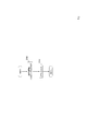
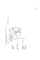
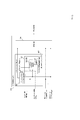
- the sound signal downmix device 401 of the first example includes the left-right relationship information estimation unit 183 and the downmix unit 112.
- the sound signal downmix device 401 obtains and outputs a downmix signal, which will be described later, from the input sound signal in the time domain of the 2-channel stereo, for example, in frame units having a predetermined time length of 20 ms.
- the sound signal input to the sound signal downmix device 401 is a sound signal in the time region of 2-channel stereo. For example, it is obtained by collecting sounds such as voice and music with each of two microphones and performing AD conversion.
- the downmix signal which is a monaural sound signal in the time domain obtained by the sound signal downmix device 401, is input to at least a coding device that encodes the downmix signal or at least a signal processing device that processes the downmix signal. ..
- the sound signal downmix device 401 has the left channel input sound signal x L (1), x L (2), ..., x L (T) and the right channel in frame units.
- the input sound signal x R (1), x R (2), ..., x R (T) is input, and the sound signal downmix device 401 uses the downmix signal x M (1), x M (on a frame-by-frame basis). 2), ..., x M (T) is obtained and output.
- T is a positive integer, for example, if the frame length is 20 ms and the sampling frequency is 32 kHz, T is 640.
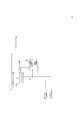
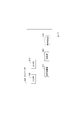
- the sound signal downmix device 401 of the first example performs the processing of step S183 and step S112 illustrated in FIG. 2 for each frame.
- the left channel input sound signal input to the sound signal downmix device 401 and the right channel input sound signal input to the sound signal downmix device 401 are input to the left-right relationship information estimation unit 183.
- the left-right relationship information estimation unit 183 obtains and outputs the left-right correlation value ⁇ and the preceding channel information from the left channel input sound signal and the right channel input sound signal (step S183).
- the preceding channel information corresponds to whether the sound emitted by the main sound source in a certain space reaches the microphone for the left channel arranged in the space or the microphone for the right channel arranged in the space earlier.
- the preceding channel information is information indicating whether the same sound signal is included in the left channel input sound signal or the right channel input sound signal first.
- the same sound signal is included in the left channel input sound signal first, it is said that the left channel precedes or the right channel follows, and the same sound signal precedes the right channel input sound signal.
- the right channel is leading or the left channel is following, and the leading channel information is information indicating which channel, the left channel or the right channel, is leading. be.
- the left-right correlation value ⁇ is a correlation value considering the time difference between the left channel input sound signal and the right channel input sound signal. That is, the left-right correlation value ⁇ is a sample sequence of the input sound signal of the preceding channel, a sample sequence of the input sound signal of the trailing channel at a position shifted behind the sample sequence by ⁇ sample, and the like. It is a value indicating the magnitude of the correlation of. In the following, this ⁇ is also referred to as a left-right time difference. Since the preceding channel information and the left-right correlation value ⁇ are information representing the relationship between the left channel input sound signal and the right channel input sound signal, they can be said to be left-right relationship information.
- the left-right relationship information estimation unit 183 uses a predetermined ⁇ max to ⁇ min (for example, ⁇ max is a positive number, ⁇ .
- ⁇ max is a positive number, ⁇ .
- ⁇ cand min is a negative number
- ⁇ cand a sample sequence of the left channel input sound signal and a sample of the right channel input sound signal located behind the sample sequence by the number of each candidate sample number ⁇ cand.
- the left-right relationship information estimation unit 183 obtains and outputs information indicating that the left channel is ahead as the leading channel information.
- the information indicating that the right channel is ahead may be obtained and output as the leading channel information, but the information indicating that none of the channels is leading may be obtained and output as the leading channel information. It is good to do.
- one or more samples of the past input sound signals continuous with the sample sequence of the input sound signals of the current frame may also be used.
- the past The sample sequence of the input sound signal of the frame may be stored in a storage unit (not shown) in the left-right relationship information estimation unit 183 for a predetermined number of frames.
- the correlation value using the signal phase information may be set as ⁇ cand as follows.
- the left-right relationship information estimation unit 183 first determines the left channel input sound signal x L (1), x L (2), ..., x L (T) and the right channel input sound signal x R (1). ), X R (2), ..., x R (T) from 0 to T-1 by Fourier transforming each of them as shown in the following equations (1-1) and (1-2). Obtain the frequency spectra X L (k) and X R (k) at each frequency k of.
- the left-right relationship information estimation unit 183 uses the frequency spectra X L (k) and X R (k) at each frequency k obtained by the equations (1-1) and (1-2) as follows.
- the spectrum ⁇ (k) of the phase difference at each frequency k is obtained by the equation (1-3) of.
- the left-right relationship information estimation unit 183 then performs an inverse Fourier transform on the spectrum of the phase difference obtained by the equation (1-3), from ⁇ max to ⁇ min as shown in the following equation (1-4).
- the phase difference signal ⁇ ( ⁇ cand ) is obtained for each candidate sample number ⁇ cand.
- the absolute value of the phase difference signal ⁇ ( ⁇ cand ) obtained by Eq. (1-4) is the left channel input sound signal x L (1), x L (2), ..., x L (T) and Since it represents a kind of correlation corresponding to the plausibility of the time difference of the right channel input sound signal x R (1), x R (2), ..., x R (T), the left-right relationship information estimation unit 183 uses the absolute value of this phase difference signal ⁇ ( ⁇ cand ) for each candidate sample number ⁇ cand as the correlation value ⁇ cand .
- the left-right relationship information estimation unit 183 obtains and outputs the maximum value of the correlation value ⁇ cand , which is the absolute value of the phase difference signal ⁇ ( ⁇ cand ), as the left-right correlation value ⁇ , and outputs the maximum value when the correlation value is the maximum value.
- ⁇ cand is a positive value
- information indicating that the left channel is leading is obtained and output as leading channel information
- ⁇ cand is a negative value when the correlation value is the maximum value.
- Information indicating that the right channel is ahead is obtained and output as the leading channel information.
- the left-right relationship information estimation unit 183 may obtain and output information indicating that the left channel is ahead as the leading channel information.
- the left-right relationship information estimation unit 183 uses the absolute value of the phase difference signal ⁇ ( ⁇ cand ) as it is as the correlation value ⁇ cand , for example, the absolute value of the phase difference signal ⁇ ( ⁇ cand ) for each ⁇ cand.
- a normalized value such as a relative difference from the average of the absolute values of the phase difference signals obtained for each of the plurality of candidate samples before and after ⁇ cand may be used.
- the left-right relation information estimation unit 183 obtains an average value by the following equation (1-5) for each ⁇ cand using a predetermined positive number ⁇ range , and the obtained average value ⁇ c (
- the normalized correlation value obtained by the following equation (1-6) using ⁇ cand ) and the phase difference signal ⁇ ( ⁇ cand ) may be used as ⁇ cand.
- the normalized correlation value obtained by Eq. (1-6) is a value of 0 or more and 1 or less, ⁇ cand is so close to 1 that it is plausible as a left-right time difference, and ⁇ cand is not plausible as a left-right time difference. It is a value showing a property close to 0.
- the left channel input sound signal input to the sound signal downmix device 401, the right channel input sound signal input to the sound signal downmix device 401, and the left-right relationship information estimation unit 183 were output to the downmix unit 112.
- the left-right correlation value ⁇ and the preceding channel information output by the left-right relationship information estimation unit 183 are input.
- the downmix unit 112 includes the downmix signal so that the input sound signal of the preceding channel of the left channel input sound signal and the right channel input sound signal is included more as the left-right correlation value ⁇ is larger.
- the left channel input sound signal and the right channel input sound signal are weighted and averaged to obtain a downmix signal and output (step S112).
- the downmix unit 112 uses a weight determined by the left-right correlation value ⁇ for each corresponding sample number t to use the left channel input sound signal x L (
- the downmix signal x M (t) may be obtained by weighting and adding t) and the right channel input sound signal x R (t).
- the downmix signal has a left channel input as the left-right correlation value ⁇ is smaller, that is, the correlation between the left channel input sound signal and the right channel input sound signal is smaller. It is closer to the signal obtained by averaging the sound signal and the right channel input sound signal, and the larger the left-right correlation value ⁇ , that is, the larger the correlation between the left channel input sound signal and the right channel input sound signal, the more the left channel input sound signal and the right. It is close to the input sound signal of the preceding channel among the channel input sound signals.
- ⁇ Second example ⁇ For example, when a device other than the sound signal downmix device performs stereo coding processing on the left channel input sound signal and the right channel input sound signal, the left channel input sound signal and the right channel input sound signal are combined with the sound signal downmix device. Is a signal obtained by stereo decoding processing by another device, and in some cases, the same left-right correlation value ⁇ and one or both of the preceding channel information obtained by the left-right relation information estimation unit 183 are down. It may be obtained by a device different from the mixing device. If either or both of the left-right correlation value ⁇ and the preceding channel information are obtained by another device, the sound signal downmixing device is provided with one of the left-right correlation value ⁇ and the preceding channel information obtained by another device.
- both may be input so that the left-right relationship information estimation unit 183 obtains the left-right correlation value ⁇ or the preceding channel information that has not been input to the sound signal downmix device.
- the left-right relationship information estimation unit 183 obtains the left-right correlation value ⁇ or the preceding channel information that has not been input to the sound signal downmix device.
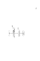
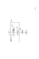
- the sound signal downmix device 405 of the second example includes the left-right relationship information acquisition unit 185 and the downmix unit 112.
- the sound signal downmix device 405 in addition to the left channel input sound signal and the right channel input sound signal, as shown by the alternate long and short dash line in FIG. 3, either the left-right correlation value ⁇ obtained by another device or the preceding channel information is used. Or both may be entered.
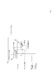
- the sound signal downmix device 405 of the second example performs the processes of steps S185 and S112 illustrated in FIG. 4 for each frame. Since the downmix unit 112 and the step S112 are the same as those in the first example, the left-right relationship information acquisition unit 185 and the step S185 will be described below.
- the left-right correlation value ⁇ which is a value indicating the magnitude of the correlation between the left channel input sound signal and the right channel input sound signal, and which of the left channel input sound signal and the right channel input sound signal precedes.
- the preceding channel information which is information indicating whether or not the signal is generated, is obtained and output (step S185).
- the left-right relationship information acquisition unit 185 is the sound signal downmix device as shown by the alternate long and short dash line in FIG.
- the left-right correlation value ⁇ and the preceding channel information input to 405 are obtained and output to the downmix unit 112.
- the left-right relationship information acquisition unit 185 When either the left-right correlation value ⁇ or the preceding channel information is not input to the sound signal downmix device 405 from another device, the left-right relationship information acquisition unit 185 has a left-right relationship as shown by a broken line in FIG.
- the information estimation unit 183 is provided.
- the left-right relationship information estimation unit 183 of the left-right relationship information acquisition unit 185 uses the left-right correlation value ⁇ that is not input to the sound signal downmix device 405 or the preceding channel information that is not input to the sound signal downmix device 405 as the first example. It is obtained from the left channel input sound signal and the right channel input sound signal and output to the downmix unit 112 in the same manner as the left-right relation information estimation unit 183.
- the left-right relationship information acquisition unit 185 displays the sound as shown by a single point chain line in FIG.
- the left-right correlation value ⁇ input to the signal downmix device 405 or the preceding channel information input to the sound signal downmix device 405 is output to the downmix unit 112.
- the left-right relationship information acquisition unit 185 is the left-right relationship information estimation unit as shown by the broken line in FIG. 183 is provided.
- the left-right relationship information estimation unit 183 obtains the left-right correlation value ⁇ and the preceding channel information from the left channel input sound signal and the right channel input sound signal in the same manner as the left-right relationship information estimation unit 183 of the first example, and the downmix unit 112. Output to. That is, it can be said that the left-right relationship information estimation unit 183 and step S183 of the first example are in the categories of the left-right relationship information acquisition unit 185 and step S185, respectively.
- the first embodiment In the sound signal downmixing devices 401 and 405, for each nth channel, the greater the correlation between the input sound signal of the channel following the nth channel and the input sound signal of the nth channel, the greater the correlation between the input sound of the nth channel and the input sound of the nth channel.
- the downmix signal includes a signal with a large weight, and the greater the correlation between the input sound signal of the channel preceding the nth channel and the input sound signal of the nth channel, the greater the correlation between the input sound of the nth channel and the input sound of the nth channel.
- the downmix signal includes a signal with a small weight. The relationship between this input sound signal and the downmix signal is as follows: when there are multiple leading channels, when there are multiple trailing channels, both the leading channel and the trailing channel. If there is, the sound signal downmixing device of the second embodiment has been expanded so as to cope with. Hereinafter, the sound signal downmix device of the second embodiment will be described.
- the sound signal downmix device of the second embodiment is an extension of the sound signal downmix device of the first embodiment so as to correspond to a case where the number of channels is 3 or more, and when the number of channels is 2. Operates in the same manner as the sound signal downmix device of the first embodiment.
- the sound signal downmixing devices 401 and 405 obtain a downmix signal closer to the signal obtained by averaging all the input sound signals as the correlation between the channels of the input sound signals becomes smaller.
- the sound signal downmix device of the second embodiment will be described as an example.
- the sound signal downmix device 406 of the first example includes an interchannel relationship information estimation unit 186 and a downmix unit 116.
- the sound signal downmix device 406 obtains and outputs a downmix signal, which will be described later, from the input sound signal in the time domain of the N-channel stereo, for example, in frame units having a predetermined time length of 20 ms.
- the number of channels N is an integer of 2 or more. However, when the number of channels is 2, the sound signal downmixing device of the first embodiment may be used. Therefore, the sound signal downmixing device of the second embodiment is particularly useful when N is an integer of 3 or more. ..
- the sound signal input to the sound signal downmix device 406 is a sound signal in the time region of N channels. For example, it is obtained by collecting sounds such as voice and music with each of N microphones and performing AD conversion. Digital sound signals obtained by collecting and AD-converting digital sound signals at multiple points, or by mixing digital sound signals of one channel or multiple channels as they are or by appropriately mixing them into N channels. These are a signal, a digital decoded sound signal obtained by encoding and decoding each of the above-mentioned digital sound signals, and a digital signal-processed sound signal obtained by signal-processing each of the above-mentioned digital sound signals.
- the downmix signal which is a monaural sound signal in the time domain obtained by the sound signal downmix device 406, is input to at least a coding device that encodes the downmix signal or at least a signal processing device that processes the downmix signal. ..
- Input sound signals of N channels are input to the sound signal downmix device 406 in frame units, and the sound signal downmix device 406 obtains and outputs downmix signals in frame units.
- T is a positive integer, for example, if the frame length is 20ms and the sampling frequency is 32kHz, then T is 640.
- the sound signal downmix device 406 of the first example performs the processes of steps S186 and S116 illustrated in FIG. 6 for each frame.
- Interchannel relationship information estimation unit 186 Input sound signals of N channels input to the sound signal downmix device 406 are input to the channel-to-channel relationship information estimation unit 186.
- the inter-channel relationship information estimation unit 186 obtains and outputs the inter-channel correlation value and the preceding channel information from the input sound signals of the input N channels (step S186). Since the inter-channel correlation value and the preceding channel information represent the inter-channel relationship in the input sound signals of N channels, it can be said to be the inter-channel relationship information.
- the inter-channel correlation value is a value representing the magnitude of the correlation in consideration of the time difference between the input sound signals for each pair of the two channels included in the N channels.
- n is an integer of 1 or more and N or less
- m is an integer greater than n and N or less
- the interchannel correlation value between the nth channel input sound signal and the m channel input sound signal is ⁇ nm .
- the interchannel relationship information estimation unit 186 obtains an interchannel correlation value ⁇ nm for each of (N ⁇ (N-1)) / 2 combinations of n and m.
- the preceding channel information is information indicating which of the input sound signals of the two channels contains the same sound signal first for each combination of the two channels included in the N channels. This is information indicating which channel of the individual channels precedes.
- the interchannel relationship information estimation unit 186 has the above-mentioned (N ⁇ (N-1)) / 2 ways. Obtain the leading channel information INFO nm for each combination of n and m. In the following, for the combination of n and m, if the same sound signal is included in the nth channel input sound signal before the mth channel input sound signal, the nth channel is the mth channel.
- the nth channel is ahead of the mth channel, the mth channel is behind the nth channel, the mth channel is behind the nth channel, etc. There is that.
- the m-th channel becomes the n-th channel.
- the mth channel is ahead of the nth channel, the nth channel is behind the mth channel, the nth channel is behind the mth channel, And so on.
- the interchannel relationship information estimation unit 186 sets the interchannel correlation value ⁇ nm and the preceding channel information INFO nm for each of the above-mentioned (N ⁇ (N-1)) / 2 combinations of the nth channel and the mth channel. It may be obtained in the same manner as the left-right relationship information estimation unit 183 of the first embodiment. That is, the inter-channel relationship information estimation unit 186 reads, for example, the left channel in each example of the description of the left-right relationship information estimation unit 183 of the first embodiment as the nth channel, the right channel as the mth channel, and L.
- Is read as n R is read as m
- leading channel information is read as leading channel information INFO nm
- left-right correlation value ⁇ is read as inter-channel correlation value ⁇ nm .
- the channel-to-channel relationship information estimation unit 186 can be used with the above-mentioned (N ⁇ (N-1)) / 2 ways of nth channel. For each combination of the m-th channel, the sample sequence of the n-channel input sound signal for each candidate sample number ⁇ cand from ⁇ max to ⁇ min and the sample sequence for each candidate sample number ⁇ cand. The maximum value of the absolute value ⁇ cand of the correlation coefficient between the sample string of the m-channel input sound signal located at a later position is obtained as the interchannel correlation coefficient ⁇ nm and output, and the correlation coefficient is calculated.
- the information indicating that the m-th channel is ahead may be obtained and output as the leading channel information INFO nm , or the information indicating that the mth channel is leading may be obtained and output as the leading channel information INFO nm.
- ⁇ max and ⁇ min are the same as in the first embodiment.
- the correlation value using the signal phase information may be set as ⁇ cand as follows.
- the channel-to-channel relationship information estimation unit 186 first applies the input sound signals x i (1), x i (2) for each channel i from the first channel input sound signal to the Nth channel input sound signal.
- x i (T) By Fourier transforming, ..., x i (T) as in the following equation (2-1), the frequency spectrum X i (k) at each frequency k from 0 to T-1 is obtained.
- the channel-to-channel relationship information estimation unit 186 performs the subsequent processing for each of the above-mentioned (N ⁇ (N-1)) / 2 combinations of the nth channel and the mth channel.
- Inter-channel relationship information estimation unit 186 first, using the equation (2-1) frequency spectrum of the n-channel in each frequency k obtained in X n (k) and the frequency spectrum X m of the m channels (k) Then, the spectrum ⁇ (k) of the phase difference at each frequency k is obtained by the following equation (2-2).
- the channel-to-channel relationship information estimation unit 186 performs an inverse Fourier transform on the spectrum of the phase difference obtained by the equation (2-2), so that the spectrum from ⁇ max to ⁇ min is obtained as in the equation (1-4).
- a phase difference signal ⁇ ( ⁇ cand ) is obtained for each candidate sample number ⁇ cand.
- the interchannel relationship information estimation unit 186 obtains and outputs the maximum value of the correlation value ⁇ cand , which is the absolute value of the phase difference signal ⁇ ( ⁇ cand ), as the interchannel correlation value ⁇ nm , and the correlation value is the maximum value.
- the channel-to-channel relationship information estimation unit 186 obtains and outputs information indicating that the nth channel is ahead as the leading channel information INFO nm.
- the information indicating that the mth channel is ahead may be obtained and output as the leading channel information INFO nm.
- the channel-to-channel relationship information estimation unit 186 uses the absolute value of the phase difference signal ⁇ ( ⁇ cand ) as the correlation value ⁇ cand as it is, for example, for each ⁇ cand .
- a normalized value such as the relative difference from the average of the absolute values of the phase difference signals obtained for each of the multiple candidate samples before and after ⁇ cand with respect to the absolute value of the phase difference signal ⁇ ( ⁇ cand). You may use it. That is, the inter-channel relationship information estimation unit 186 obtains an average value by Eq. (1-5) for each ⁇ cand using a predetermined positive number ⁇ range , and the obtained average value ⁇ c ( ⁇ ).
- the normalized correlation value obtained by Eq. (1-6) using cand) and the phase difference signal ⁇ ( ⁇ cand ) may be used as ⁇ cand.
- the downmix unit 116 includes the input sound signals of N channels input to the sound signal downmix device 406 and the above-mentioned (N ⁇ (N-1)) / 2 output by the channel-to-channel relationship information estimation unit 186.
- the inter-channel correlation value ⁇ nm that is, the inter-channel correlation value for each combination of two channels included in the N channels
- the inter-channel relationship information estimation unit 186 Preceding channel information for each of the above-mentioned (N ⁇ (N-1)) / 2 combinations of n and m output INFO nm (that is, predecessor for each combination of two channels included in N channels) Channel information) and is input.
- the downmix unit 116 has a smaller correlation between the input sound signal of each channel and the input sound signal of each channel preceding the channel, and is smaller than the input sound signal of each channel following the channel. The larger the correlation is, the larger the weight is given, and the input sound signals of N channels are weighted and added to obtain a downmix signal and output (step S116).
- the channel number (channel index) of each channel is i
- the input sound signal of the i-th channel is x i (1), x i (2), ..., x i (T)
- the downmix signal is x.
- Specific example 1 of the downmix unit 116 will be described as M (1), x M (2), ..., x M (T).
- the inter-channel correlation value is a value of 0 or more and 1 or less, like the absolute value or the normalized value of the correlation coefficient of the above-mentioned example in the explanation part of the inter-channel relationship information estimation unit 186. And.
- M is not a channel number, but a subscript intended that the downmix signal is a monaural signal.
- the downmix unit 116 obtains a downmix signal, for example, by performing the processes of steps S116-1 to S116-3 described below.
- the downmix unit 116 is a combination of two channels (N-1) including the i-th channel of the preceding channel information INFO nm input to the downmix unit 116. From the preceding channel information, a set of channel numbers I Li of the channel preceding the i-th channel and a set of channel numbers I Fi of the channels following the i-th channel are obtained. (Step S116-1).
- the downmix unit 116 uses two channels (N-1) including the i-th channel of the interchannel correlation value ⁇ nm input to the downmix unit 116 for each i-th channel.
- the inter-channel correlation value ⁇ mn is the same as the inter-channel correlation value ⁇ nm for each of the above combinations of n and m
- the inter- channel correlation value ⁇ ij when i is a value larger than j is also used.
- the interchannel correlation value ⁇ ik when i is a value larger than k is also included in the interchannel correlation value ⁇ nm input to the downmix unit 116.
- the input sound signals of the i-th channel from i to N are then x i (1), x i (2), ..., x i (T), and i is from 1.
- x i (1), x i (2), ..., x i (T) the weight w i of each i-th channel up to N and the downmix signal sample x M (t) for each sample number t (sample index t) by the following equation (2-4).
- Get the downmix signals x M (1), x M (2), ..., x M (T) (step S116-3).
- the downmix unit 116 does not perform step S116-2 and step S116-3 in order, but uses an equation in which the weight w i of the equation (2-4) is replaced with the right side of the equation (2-3).
- a downmix signal may be obtained. That is, the downmix unit 116 sets the set of channel numbers of the channels preceding the i-th channel for each i-channel as I Li, and for each i-channel, for the i-channel. Let I Fi be the set of channel numbers of the following channels, and for each i-channel, the channel for each combination of the i-channel and each channel j preceding the i-channel.
- each sample x M (t) of the downmix signal may be obtained by Eq. (2-4).
- Equation (2-4) is an equation for obtaining a downmix signal by weighting and adding the input sound signals of N channels, and the weight w of each i-th channel given to the input sound signal of each i-th channel in the weighted addition.
- Equation (2-3) gives i.
- the part of the following equation (2-3-A) in the equation (2-3) correlates with the input sound signal of each channel in which the input sound signal of the i-th channel precedes the i-channel. The larger the value, the smaller the weight w i.
- the input sound signal of the i-th channel and the input sound signal of the preceding channel are included. If there is even one channel with a very large correlation with, the weight w i is set to a value close to 0.
- the weight w i increases as the correlation with the input sound signal of each channel following the i-th channel increases.
- the value is set to be larger than 1.
- the total value of all channels of the weight w i obtained by the downmix unit 116 in step S116-1 of the specific example 1 may not be 1, the total value of all channels of the weight of the downmix unit 116 is 1.
- the value obtained by normalizing the weight w i of each i-th channel can be used instead of the weight w i in Eq. (2-4), or the weight w i so that the total value of all the channels of the weight becomes 1.
- the downmix signal may be obtained by using an equation obtained by modifying equation (2-4) so as to include normalization. This example will be described as a specific example 2 of the downmix unit 116, which is different from the specific example 1.
- downmixing unit 116 a weight w i for each i-th channel to obtain the equation (2-3), normal to the weight w i for each i-th channel is the sum of all the channels it becomes 1 turned into 'to obtain i (i.e., each for the i-th channel by the following equation (2-5) regular Kasumi weight w' normal Kasumi weight w to obtain a i), the respective i from 1 to N i-channel input sound signal x i of (1), x i (2 ), ..., with x i (T) and the normal Kasumi weight w 'i, the following for each sample number t formula (2
- the downmix signals x M (1), x M (2), ..., x M (T) may be obtained.
- the downmix unit 116 sets the set of channel numbers of the channels preceding the i-th channel for each i-channel as I Li, and for each i-channel, for the i-channel.
- I Fi be the set of channel numbers of the following channels, and for each i-channel, the channel for each combination of the i-channel and each channel j preceding the i-channel.
- ⁇ ij be the inter-channel correlation value
- ⁇ ik be the inter-channel correlation value for each combination of the i-channel and each channel k following the i-channel for each i-channel.
- ⁇ Second example ⁇ For example, when a device different from the sound signal downmix device stereo-encodes the input sound signals of N channels, the input sound signals of N channels are stereo by a device different from the sound signal downmix device.
- any or all of the same inter-channel correlation value ⁇ nm and preceding channel information INFO nm obtained by the inter-channel relationship information estimation unit 186 are sound signal downmixing devices. It may be obtained by a different device. If any or all of the interchannel correlation value ⁇ nm and the preceding channel information INFO nm are obtained by another device, the sound signal downmix device is provided with the interchannel correlation value ⁇ nm obtained by another device and the preceding channel.
- the channel-to-channel relationship information estimation unit 186 obtains the inter-channel correlation value ⁇ nm and the preceding channel information INFO nm that were not input to the sound signal downmix device. It should be.
- the following is an example of a sound signal downmixing device assuming that any or all of the inter-channel correlation value ⁇ nm and the preceding channel information INFO nm are input from the outside, focusing on the differences from the first example.
- any or all of the inter-channel correlation value ⁇ nm and the preceding channel information INFO nm are input from the outside, focusing on the differences from the first example.
- the sound signal downmix device 407 of the second example includes an interchannel relationship information acquisition unit 187 and a downmix unit 116.
- the sound signal downmix device 407 in addition to the input sound signals of N channels, as shown by the alternate long and short dash line in FIG. 7, either the interchannel correlation value ⁇ nm obtained by another device or the preceding channel information INFO nm. Or all may be entered.
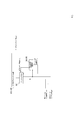
- the sound signal downmix device 407 of the second example performs the processes of steps S187 and S116 illustrated in FIG. 8 for each frame. Since the downmix unit 116 and the step S116 are the same as those in the first example, the interchannel relationship information acquisition unit 187 and the step S187 will be described below.
- the inter-channel relationship information acquisition unit 187 has an inter-channel correlation value ⁇ nm , which is a value indicating the magnitude of correlation for each combination of two channels included in N channels, and 2 included in N channels.
- ⁇ nm is a value indicating the magnitude of correlation for each combination of two channels included in N channels, and 2 included in N channels.
- the preceding channel information INFO nm which is information indicating which of the input sound signals of the two channels contains the same sound signal first, is obtained and output (step S187). ).
- the channel-to-channel relationship information acquisition unit 187 is shown by the alternate long and short dash line in FIG.
- the inter-channel correlation value ⁇ nm and the preceding channel information INFO nm input to the sound signal downmix device 407 are obtained and output to the downmix unit 116.
- the channel-to-channel relationship information acquisition unit. 187 includes an inter-channel relationship information estimation unit 186.
- the channel-to-channel relationship information estimation unit 186 of the channel-to-channel relationship information acquisition unit 187 has a channel-to-channel correlation value ⁇ nm that has not been input to the sound signal downmix device 407 or a preceding channel information INFO that has not been input to the sound signal downmix device 407.
- nm is obtained from the input sound signals of N channels in the same manner as in the interchannel relationship information estimation unit 186 of the first example, and is output to the downmix unit 116.
- the channel-to-channel relationship information acquisition unit 187 is shown by a single point chain line in FIG.
- the interchannel correlation value ⁇ nm input to the sound signal downmix device 407 or the preceding channel information INFO nm input to the sound signal downmix device 407 is output to the downmix unit 116.
- the channel-to-channel relationship information acquisition unit 187 The interchannel relationship information estimation unit 186 is provided.
- the inter-channel relationship information estimation unit 186 obtains the inter-channel correlation value ⁇ nm and the preceding channel information INFO nm from the input sound signals of N channels in the same manner as the inter-channel relationship information estimation unit 186 of the first example, and downs. Output to the mix unit 116. That is, it can be said that each of the inter-channel relationship information estimation unit 186 and step S186 of the first example is in the category of the inter-channel relationship information acquisition unit 187 and step S187.
- the channel-to-channel relationship information acquisition unit 187 is provided with the channel-to-channel relationship information estimation unit 186. Then, in the same manner as described above, what is obtained by another device and input to the sound signal downmix device 407 is output to the downmix unit 116 by the channel-to-channel relationship information acquisition unit 187 and obtained by the other device.
- the channel-to-channel relationship information estimation unit 186 obtains it from the input sound signals of N channels like the channel-to-channel relationship information estimation unit 186 of the first example, and goes down. It may be output to the mix unit 116.
- the inter-channel relationship information estimation unit 186 of the second embodiment needs to obtain the inter-channel correlation value ⁇ nm and the preceding channel information INFO nm for each combination of the two channels included in the N channels. Since there are (N ⁇ (N-1)) / 2 combinations of the two channels included in the N channels, the method illustrated in the description of the interchannel relationship information estimation unit 186 of the second embodiment. If the inter-channel correlation value ⁇ nm and the preceding channel information INFO nm are obtained in, the amount of arithmetic processing may become an issue when the number of channels is large.
- the sound signal down including the inter-channel relationship information estimation process for approximately obtaining the inter-channel correlation value ⁇ nm and the preceding channel information INFO nm by a method with a smaller amount of arithmetic processing than the inter-channel relationship information estimation unit 186.
- the mixing device will be described.
- the downmix process of the third embodiment is the same as that of the second embodiment.
- the downmix process performed by the downmix unit 116 of the second embodiment is, for example, when only the same sound emitted by a certain sound source is included in the signals of a plurality of channels with a time difference.
- This is a process for including the input sound signal of the earliest included channel among the input sound signals of a plurality of channels in the downmix signal.
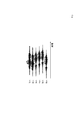
- This processing will be described with an example in which the number of channels is 6, and the input sound signals of the first channel (1ch) to the sixth channel (6ch) are the signals schematically shown in FIG.
- the first channel input sound signal and the second channel input sound signal are signals in which only the same first sound signal emitted by the first sound source is included with a time difference, and the first The sound signal is included in the second channel input sound signal earliest.
- the third channel input sound signal to the sixth channel input sound signal are signals in which only the same second sound signal emitted by the second sound source is included with a time difference.
- the sound signal of 2 is included in the 6th channel input sound signal earliest.
- the time difference between non-adjacent channels is approximately obtained by the following equations using the time differences ⁇ 12 , ⁇ 23 , ⁇ 34 , ⁇ 45 , and ⁇ 56 between adjacent channels, and the obtained channels are obtained. There is no problem even if the preceding channel information INFO nm is approximately obtained depending on whether the time difference is positive, negative, or 0.
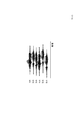
- the inter-channel correlation value ⁇ nm and the preceding channel information INFO nm can be approximately obtained by using the above equations because the input sound signals having the same or similar waveforms are continuous as illustrated in FIG. As illustrated in FIG. 10, when there are channels having the same or similar waveforms of the input sound signals but having significantly different waveforms of the input sound signals, the waveforms of the input sound signals are significantly different from each other.
- the interchannel correlation value ⁇ nm and the preceding channel information INFO nm cannot be approximately obtained using the above equations. Therefore, in the sound signal downmixing apparatus of the third embodiment, there is no channel in which the waveforms of the input sound signals are significantly different between the channels having the same or similar waveforms of the input sound signals of N channels.
- the inter-channel correlation value ⁇ nm and the preceding channel information INFO nm are obtained for the adjacent channels after the sorting, and the inter-channel correlation value ⁇ nm and the preceding channel information between the adjacent channels after the sorting are obtained.
- the other interchannel correlation values ⁇ nm and the preceding channel information INFO nm are obtained approximately.
- the sound signal downmix device 408 of the first example includes an interchannel relationship information estimation unit 188 and a downmix unit 116.
- the sound signal downmix device 408 of the first example performs the processes of step S188 and step S116 illustrated in FIG. 6 for each frame. Since the downmix unit 116 and step S116 are the same as the first example of the second embodiment, the interchannel relationship information estimation unit 188 and step S188 different from the first example of the second embodiment will be described below.
- the sound signal downmixing device 408 is input to the sound signal in the time region of N channels as in the sound signal downmixing device 408 of the first embodiment of the second embodiment, and the sound signal downmixing device 408 is used. What is obtained and output is a downmix signal which is a monaural sound signal in the time region as in the sound signal downmix device 406 of the first example of the second embodiment.
- the interchannel relationship information estimation unit 188 includes, for example, a channel rearrangement unit 1881, an adjacent channel relationship information estimation unit 1882, and an interchannel relationship information complementing unit 1883.
- the interchannel relationship information estimation unit 188 processes, for example, step S1881, step S1882, and step S1883 illustrated in FIG. 12 for each frame (step S188).
- the channel rearrangement unit 1881 sequentially, for example, sequentially from the first channel so that the channel having the highest degree of similarity in the waveform of the input sound signal becomes the adjacent channel when the time difference among the remaining channels is aligned.
- the first sorted input sound signal which is the signal after sorting of N channels, the Nth sorted input sound signal, and each sorted input sound signal are down.
- the first original channel information c 1 to the Nth original channel information c N which is the channel number (that is, the channel number of the input sound signal) when input to the mixing device 408, is obtained and output (step S1881A).
- the channel rearrangement unit 1881 determines the degree of similarity of the waveforms when the time differences are aligned, such as a value indicating the closeness of the distance between the input sound signals of the two channels when the time differences are aligned, and when the time differences are aligned.
- the inner product of the input sound signals of the two channels may be divided by the synergistic average of the energies of the input sound signals of the two channels to represent the magnitude of the correlation.
- the channel rearrangement unit 1881 can be used. Steps S1881A-1 to S1881A-N are performed below. First, the channel sorting unit 1881 obtains the first channel input sound signal as the first sorted input sound signal, and obtains the channel number "1" of the first channel as the first original channel information c 1 ( Step S1881A-1).
- the channel rearrangement unit 1881 is set to predetermined ⁇ max to ⁇ min for each channel m of the second channel to the Nth channel (for example, ⁇ max is a positive number and ⁇ min is a negative number).
- ⁇ max is a positive number
- ⁇ min is a negative number.
- ⁇ cand a sample sequence of the first sorted input sound signal, a sample sequence of the m-channel input sound signal located behind the sample sequence by the number of candidate samples ⁇ cand, and The input sound signal of the channel m having the minimum distance is obtained as the second rearranged input sound signal, and the channel number of the channel m having the minimum distance is obtained as the second original channel information c 2 (Step S1881A-2).
- channel rearranging unit 1881 still for each candidate sample number tau cand from tau max for each channel m which is not a rearrangement already input sound signal to tau min of the second channel of the second N-channel, the 2 Obtain the distance between the sample sequence of the rearranged input sound signal and the sample sequence of the m-channel input sound signal located behind the sample sequence by the number of each candidate sample ⁇ cand, and the distance is the minimum.
- the input sound signal of the channel m which is a value, is obtained as the third rearranged input sound signal, and the channel number of the channel m, which has the minimum distance, is obtained as the third original channel information c 3 (step S1881A-3).
- the fourth original channel information c 4 to the (N-1) original channel information c (N-1) are obtained (step S1881A-4 to step S1881A- (N-1)).
- the channel sorting unit 1881 obtains the input sound signal of the remaining one channel which has not been made into the sorted input sound signal as the Nth sorted input sound signal, and the remaining which has not been made into the sorted input sound signal yet.
- the channel number of one channel is obtained as the Nth original channel information c N (step S1881A-N).
- the nth sorted input sound signal for each n of 1 or more and N or less is also referred to as the input sound signal of the nth channel after sorting, and n of the nth sorted input sound signal. This is also called the channel number after sorting.
- the channel rearranging unit 1881 may rearrange the input sound signals of N channels so that there are no channels having the same or similar waveforms of the input sound signals but having significantly different waveforms of the input sound signals. In consideration of the purpose and the fact that the amount of arithmetic processing required for the sorting process should be small, the degree of similarity may be evaluated and the sorting may be performed without adjusting the time difference. For example, the channel rearranging unit 1881 may perform steps S1881B-N from the following steps S1881B-1. First, the channel sorting unit 1881 obtains the first channel input sound signal as the first sorted input sound signal, and obtains the channel number "1" of the first channel as the first original channel information c 1 ( Step S1881B-1).
- the channel rearrangement unit 1881 obtains the distance between the sample sequence of the first rearranged input sound signal and the sample sequence of the mth channel input sound signal for each channel m of the second channel to the Nth channel.
- the input sound signal of the channel m having the minimum distance is obtained as the second rearranged input sound signal, and the channel number of the channel m having the minimum distance is obtained as the second original channel information c 2 (step S1881B). -2).
- the channel sorting unit 1881 sets a sample sequence of the second sorted input sound signal and the m-channel input for each channel m of the second to N channels that has not yet been used as the sorted input sound signal.
- the distance from the sample sequence of the sound signal is obtained, the input sound signal of the channel m having the minimum distance is obtained as the third rearranged input sound signal, and the channel number of the channel m having the minimum distance is obtained. Obtained as 3 original channel information c 3 (step S1881B-3).
- the same process is repeated until there is only one channel that has not yet been sorted as an input sound signal, from the fourth sorted input sound signal to the (N-1) sorted input sound signal.
- the fourth original channel information c 4 to the (N-1) original channel information c (N-1) are obtained (step S1881B-4 to step S1881B- (N-1)).
- the channel sorting unit 1881 obtains the input sound signal of the remaining one channel which has not been made into the sorted input sound signal as the Nth sorted input sound signal, and the remaining which has not been made into the sorted input sound signal yet.
- the channel number of one channel is obtained as the Nth original channel information c N (step S1881B-N).
- the channel rearranging unit 1881 orders the input sound signals of the remaining channels in order from the first channel, regardless of whether or not the time difference is aligned and what value is used for the degree of similarity between the signals. Is sequentially sorted so that the most similar channels are adjacent channels, and the Nth sorted input from the first sorted input sound signal, which is the signal after sorting of N channels, is performed.
- the first original channel information c 1 to the Nth original channel which is the channel number (that is, the channel number of the input sound signal) when the sound signal and each sorted input sound signal are input to the sound signal downmix device 408.
- the information c N and the information c N may be obtained and output (step S1881).
- N sorted input sound signals from the first sorted input sound signal to the Nth sorted input sound signal are input to the adjacent channel relationship information estimation unit 1882.
- the inter-channel relationship information estimation unit 1882 sets the inter-channel correlation value and the channel for each combination of the two sorted input sound signals whose rear-ordered channel numbers are adjacent to each other. The time difference between them is obtained and output (step S1882).
- the inter-channel correlation value obtained in step S1882 is a correlation value in consideration of the time difference between the sorted input sound signals for each combination of two sorted channels having adjacent sorted channel numbers, that is, It is a value indicating the magnitude of the correlation in consideration of the time difference between the sorted input sound signals.
- N-1 number of two channels included in N channels.
- n be an integer of 1 or more and N-1 or less, and set the interchannel correlation value between the nth sorted input sound signal and the (n + 1) sorted channel input sound signal to ⁇ 'n (n +).
- the inter-channel relationship information estimation unit 1882 has an inter-channel correlation value ⁇ 'for each of the combinations (N-1) of two sorted channels whose channel numbers after sorting are adjacent to each other. Get n (n + 1) .
- the time difference between channels obtained in step S1882 is how far ahead of the two sorted input sound signals that the same sound signal is for each combination of the two sorted channels whose channel numbers are adjacent to each other. It is information indicating whether it is included in. Assuming that the time difference between channels between the nth sorted input sound signal and the (n + 1) th sorted input sound signal is ⁇ 'n (n + 1) , the adjacent channel relationship information estimation unit 1882 Obtain ⁇ 'n (n + 1) as the time difference between channels for each of the combinations (N-1) of the two sorted channels whose channel numbers are adjacent to each other.
- the inter-channel relationship information estimation unit 1882 may perform the rearranged channel for each n of 1 or more and N-1 or less (that is, the channel after sorting).
- the sample sequence of the nth sorted input sound signal for each candidate sample number ⁇ cand from ⁇ max to ⁇ min.
- the correlation value using the signal phase information may be set as ⁇ cand as follows.
- the adjacent channel relationship information estimation unit 1882 first sets the input sound signals x i (1), x i (2) for each channel i from the first channel input sound signal to the Nth channel input sound signal. ), ..., x i (T) is Fourier transformed as in Eq. (2-1) to obtain the frequency spectrum X i (k) at each frequency k from 0 to T-1.
- the adjacent channel-to-adjacent relationship information estimation unit 1882 then describes each n of 1 or more and N-1 or less, that is, each combination of two sorted channels having adjacent sorted channel numbers. Is processed. Between adjacent channels related information estimating section 1882, first, the equation (2-1) frequency spectrum X n (k) of the n-channel in each frequency k obtained in and the (n + 1) channels of the frequency spectrum X ( Using n + 1) (k), the spectrum ⁇ (k) of the phase difference at each frequency k is obtained by the following equation (3-1).
- the adjacent channel relationship information estimation unit 1882 performs an inverse Fourier transform on the spectrum of the phase difference obtained by the equation (3-1), so that the spectrum from ⁇ max to ⁇ min is obtained as in the equation (1-4).
- the phase difference signal ⁇ ( ⁇ cand ) is obtained for each candidate sample number ⁇ cand of.
- the adjacent channel relationship information estimation unit 1882 obtains and outputs the maximum value of the correlation value ⁇ cand, which is the absolute value of the phase difference signal ⁇ ( ⁇ cand ), as the interchannel correlation value ⁇ 'n (n + 1). Then, ⁇ cand when the correlation value is the maximum value is obtained as the time difference between channels ⁇ 'n (n + 1) and output.
- the adjacent channel relationship information estimation unit 1882 uses the absolute value of the phase difference signal ⁇ ( ⁇ cand ) as it is as the correlation value ⁇ cand , similarly to the left / right relationship information estimation unit 183 and the channel relationship information estimation unit 186. Instead, for example, for each ⁇ cand , the relative difference between the absolute values of the phase difference signals obtained for each of the plurality of candidate samples before and after ⁇ cand with respect to the absolute value of the phase difference signal ⁇ ( ⁇ cand). Such a normalized value may be used. That is, the adjacent channel relationship information estimation unit 1882 obtained an average value by Eq. (1-5) for each ⁇ cand using a predetermined positive number ⁇ range , and the obtained average value ⁇ c ( The normalized correlation value obtained by Eq. (1-6) using ⁇ cand ) and the phase difference signal ⁇ ( ⁇ cand ) may be used as ⁇ cand.
- the inter-channel relationship information complementing unit 1883 contains the inter-channel correlation value of each combination of two sorted channels whose channel numbers after sorting are adjacent to each other, which is output by the inter-channel relationship information estimation unit 1882. The time difference between channels and the original channel information for each sorted channel output by the channel sorting unit 1881 are input.
- the inter-channel relationship information complementing unit 1883 performs the following steps S1883-1 to S1883-5 for all combinations of the two channels (that is, all combinations of the two sorting source channels).
- the inter-channel correlation value and the preceding channel information are obtained and output (step S1883).
- the inter-channel relationship information complementing unit 1883 first obtains two non-adjacent channel numbers after sorting from the inter-channel correlation value for each combination of two sorted channels whose channel numbers are adjacent to each other.
- the inter-channel correlation value for each combination of channels after rearrangement is obtained (step S1883-1).
- n be an integer of 1 or more and N-2 or less
- m be an integer of n + 2 or more and N or less
- the interchannel correlation between the nth sorted input sound signal and the mth sorted input sound signal is not adjacent' the value ⁇ get nm.
- the two channel numbers in each combination of two sorted channels that are adjacent to each other are set as i (i is an integer of 1 or more and N-1 or less) and i + 1.
- the inter-channel correlation value for each combination of two rearranged channels having adjacent channel numbers is ⁇ 'i (i + 1)
- the inter-channel relationship information complement unit 1883 has n and m.
- two adjacent channel numbers after sorting where i is n or more and m-1 or less.
- the inter-channel relationship information complementing unit 1883 obtains the inter-channel correlation value ⁇ 'nm by the following equation (3-2).
- the inter-channel relationship information complementing unit 1883 for each combination of n and m (that is, for each combination of two sorted channels whose channel numbers after sorting are not adjacent to each other), i is n or more m-. 'all geometric mean of i (i + 1), the correlation value ⁇ between channels' inter-channel correlation values for each combination by two channels channel number after rearrangement is 1 or less adjacent ⁇ obtained as nm You may. That is, the inter-channel relationship information complementing unit 1883 may obtain the inter-channel correlation value ⁇ 'nm by the following equation (3-3).
- the inter-channel correlation value is a value whose upper limit is not 1 such as the absolute value of the correlation coefficient or the normalized value
- the two sorted channel numbers are not adjacent to each other.
- the inter-channel relationship information complementing unit 1883 is multiplied by the equation (3-2) so that the inter-channel correlation value for each combination by channel does not exceed the upper limit of the value that the inter-channel correlation value can originally take. it is better to get a correlation value gamma 'nm between channels geometric mean of the formula (3-3) instead of a value.
- the interchannel correlation value ⁇ ' nm may be a value that depends on the interchannel correlation value ⁇ 'i (i + 1) of the combination.
- the inter-channel relationship information complementing unit 1883 may indicate that i is n or more for each combination of n and m (that is, for each combination of two sorted channels whose channel numbers after sorting are not adjacent to each other). 'the minimum value of i (i + 1), the correlation value ⁇ between channels' inter-channel correlation values for each combination by two channels channel number after rearrangement is 1 or less adjacent ⁇ obtained as nm You may do so. Further, for example, in the inter-channel relationship information complementing unit 1883, i is n or more m for each combination of n and m (that is, for each combination of two sorted channels whose channel numbers after sorting are not adjacent to each other).
- the correlation value gamma between channels' gamma may be obtained as nm.
- the inter-channel correlation value is a value whose upper limit is not 1 such as the absolute value of the correlation coefficient or the normalized value, the two sorted channel numbers are not adjacent to each other.
- the inter-channel correlation information complement unit 1883 uses the geometric mean instead of the multiplication value as the inter-channel correlation value so that the inter-channel correlation value for each combination by channel does not exceed the upper limit of the value that the inter-channel correlation value can originally take. it is better to be in the ⁇ 'nm.
- the two channel numbers in each combination of two sorted channels with adjacent sorted channel numbers are i (i is an integer of 1 or more and N-1 or less) and i + 1, and they are arranged.
- ⁇ 'i (i + 1) be the inter-channel correlation value for each combination of two rearranged channels whose channel numbers are adjacent to each other, and let n be an integer of 1 or more and N-2 or less, and m.
- inter-channel relationship information complementing unit In 1883, for each combination of n and m (that is, for each combination of two sorted channels whose channel numbers after sorting are not adjacent), i is n or more and m-1 or less after sorting.
- the two channel numbers in each combination of the two sorted channels whose channel numbers are adjacent to each other are i (i is an integer of 1 or more and N-1 or less) and i + 1.
- the inter-channel correlation value for each combination of two sorted channels with adjacent sorted channel numbers is ⁇ 'i (i + 1), and n is an integer of 1 or more and N-2 or less.
- m is an integer of n + 2 or more and N or less and the interchannel correlation value between the nth sorted input sound signal and the mth sorted input sound signal is ⁇ 'nm
- the interchannel relationship information is complemented.
- i is n or more and m-1 or less after sorting.
- the inter-channel correlation value for each combination of two sorted channels whose channel numbers are adjacent to each other after sorting the value obtained by the adjacent channel relationship information estimation unit 1882 is input, and after sorting, the value obtained by the inter-channel relationship information estimation unit 1882 is input. Since the inter-channel correlation value for each combination of the two rearranged channels whose channel numbers are not adjacent to each other is obtained in step S1883-1, the inter-channel relationship information complementing unit 1883 is obtained when step S1883-1 is performed. Has all the inter-channel correlation values for each of the two (N ⁇ (N-1)) / 2 combinations of the two sorted channels included in the N sorted channels. Become.
- n is an integer of 1 or more and N or less
- m is an integer greater than n and N or less
- Inter-channel relationship information compensating unit 1883 after the step S1883-1, (N ⁇ (N- 1)) / inter-channel correlation values for each combination by two rearrangement after the channel two types gamma 'nm Is associated with the combination of channels in the input sound signals of N channels (that is, the combination of the sorting source channels) using the original channel information c 1 to c N for each sorted channel.
- the interchannel correlation value between the input sound signals is obtained for each combination of the two channels included in the N channels (step S1883-2).
- the inter-channel relationship information complement unit 1883 obtains the inter-channel correlation value ⁇ nm for each of the combinations of the two channels (N ⁇ (N-1)) / 2.
- the inter-channel relationship information complementing unit 1883 also has two sorted channel numbers that are not adjacent to each other due to the time difference between the channels for each combination of the two sorted channels that are adjacent to each other. Obtain the time difference between channels for each combination of the sorted channels (step S1883-3). Let n be an integer of 1 or more and N-2 or less, m be an integer of n + 2 or more and N or less, and the channel between the nth channel sorted input sound signal and the m channel sorted input sound signal. 'When nm, inter-channel relationship information compensating unit 1883, inter-channel time difference ⁇ for each combination by two rearrangement after the channel where the channel number after the rearrangement is not adjacent' between time difference ⁇ get nm.
- the two channel numbers in each combination of two sorted channels that are adjacent to each other are set as i (i is an integer of 1 or more and N-1 or less) and i + 1.
- the inter-channel time difference for each combination of two rearranged channels having adjacent channel numbers is ⁇ 'i (i + 1)
- the inter-channel relationship information complement unit 1883 will perform each combination of n and m. (That is, for each combination of two sorted channels in which the sorted channel numbers are not adjacent), i is n or more and m-1 or less, and the sorted channel numbers are adjacent to each other.
- the time difference between the channels for each combination of the two sorted channels whose channel numbers are adjacent to each other is the one obtained by the adjacent channel relationship information estimation unit 1882, and the sorted channels are selected. Since the time difference between channels for each combination of the two rearranged channels whose numbers are not adjacent is obtained in step S1883-3, when step S1883-3 is performed, the channel-to-channel relationship information complementing unit 1883 is contacted. , There are all channel-to-channel time differences for each of the (N ⁇ (N-1)) / 2 combinations of the two sorted channels included in the N sorted channels.
- n is an integer of 1 or more and N or less
- m is an integer greater than n and N or less
- the time difference between channels for the combination of the sorted nth channel and the sorted m channel is ⁇ '.
- the channel-to-channel relationship information complementing unit 1883 is informed of each of the combinations of the two rearranged channels in (N ⁇ (N-1)) / 2. is the inter-channel time difference tau 'nm are present.
- Inter-channel relationship information compensating unit 1883 after the step S1883-3, the (N ⁇ (N-1) ) / inter-channel time difference tau 'nm for each of the combinations according to the channel after two sorting in two ways.
- N the original channel information c 1 to c N for each channel after sorting and associating it with the combination of channels in the input sound signal of N channels (that is, the combination of channels of the sorting source), N pieces.
- the time difference between channels between the input sound signals is obtained for each combination of the two channels included in the channel (step S1883-4).
- n is an integer of 1 or more and N or less
- m is an integer greater than n and N or less
- the time difference between channels between the nth channel input sound signal and the m channel input sound signal is ⁇ nm
- the channels The interrelationship information complement unit 1883 obtains the interchannel time difference ⁇ nm for each of the combinations of the two channels (N ⁇ (N-1)) / 2.
- the channel-to-channel relationship information complementing unit 1883 starts with (N ⁇ (N-1)) / 2 from the channel-to-channel time difference ⁇ nm for each of the two channel combinations (N ⁇ (N-1)). N-1))) Obtain the preceding channel information INFO nm for each of the combinations of the two channels in two ways (step S1883-5).
- the inter-channel time difference ⁇ nm is a positive value
- the inter-channel relationship information complementing unit 1883 obtains information indicating that the nth channel is ahead as the preceding channel information INFO nm , and obtains information indicating that the n-th channel is ahead, and the inter-channel time difference ⁇ .
- the information indicating that the mth channel is ahead is obtained as the leading channel information INFO nm.
- Inter-channel relationship information compensating unit 1883 for each of the combinations according to the two channels when inter-channel time difference tau nm is 0, the preceding channel information INFO nm, information indicating that the first n-channel is ahead Or the information indicating that the mth channel is ahead may be obtained as the leading channel information INFO nm.
- the inter-channel relationship information complementing unit 1883 replaces step S1883-4 and step S1883-5 with respect to each of the combinations of the two rearranged channels in (N ⁇ (N-1)) / 2.
- step S1883-4' step S1883-4 obtaining nm 'prior channel information INFO to the nm as in step S1883-5' time difference ⁇ between the channels was obtained by (N ⁇ (N-1) ) / 2 the prior channel information INFO 'nm for each combination by two rearrangement after the channel street, from the original channel information c 1 for each channel after the rearrangement using c N, the input sound of the N-channel Step S1883-5'to obtain the preceding channel information INFO nm for each combination of the two channels included in the N channels by associating with the combination of channels in the signal (that is, the combination of the channels to be sorted).
- inter-channel relationship information compensating unit 1883 (N ⁇ (N-1 )) / the channel time difference tau 'nm for each of the combination according to the two rearrangement after the channel in two ways, the original channel information c Corresponding to the combination of channels in the input sound signal of N channels using 1 to c N , and obtaining the preceding channel information based on whether the time difference between channels is positive, negative, or 0. , To obtain the preceding channel information INFO nm for each combination of the two channels included in the N channels.
- the inter-channel relationship information estimation unit 188 of the first example of the third embodiment may be used.
- the inter-channel relationship information acquisition unit 187 of the sound signal downmix device 407 includes an inter-channel relationship information estimation unit 188 in place of the inter-channel relationship information estimation unit 186, and the inter-channel relationship information acquisition unit 187 The operation may be performed by replacing the inter-channel relationship information estimation unit 186 with the inter-channel relationship information estimation unit 188.
- the device configuration of the sound signal downmix device 407 in this case is as illustrated in FIG. 7, and the processing flow of the sound signal downmix device 407 is as illustrated in FIG.
- the sound signal downmixing device of the second embodiment and the third embodiment described above may be included as a sound signal downmixing unit in the coding device for encoding the sound signal, and this embodiment will be described as the fourth embodiment.
- the sound signal coding device 106 of the fourth embodiment includes a sound signal downmix unit 407 and a coding unit 196.
- the sound signal coding device 106 of the fourth embodiment encodes a sound signal in the time domain of the input N-channel stereo in frame units having a predetermined time length of, for example, 20 ms, obtains a sound signal code, and outputs the sound signal code. ..
- the sound signal in the time region of the N-channel stereo input to the sound signal encoding device 106 is, for example, a digital sound obtained by collecting sounds such as voice and music with each of N microphones and performing AD conversion.
- the sound signal coding device 105 of the fourth embodiment performs the processes of step S407 and step S196 illustrated in FIG. 14 for each frame.
- the sound signal coding device 106 of the fourth embodiment will be described with reference to the description of the second embodiment and the third embodiment as appropriate.
- the sound signal downmix unit 407 obtains and outputs downmix signals from N input sound signals of the Nth channel input sound signal from the first channel input sound signal input to the sound signal coding device 106 (step S407). ).
- the sound signal downmix unit 407 is the same as the sound signal downmix device 407 of the second embodiment or the third embodiment, and includes an interchannel relationship information acquisition unit 187 and a downmix unit 116.
- the channel-to-channel relationship information acquisition unit 187 performs the above-mentioned step S187
- the downmix unit 116 performs the above-mentioned step S116.
- the sound signal coding device 106 includes the sound signal downmix device 407 of the second embodiment or the third embodiment as the sound signal downmix unit 407, and the sound signal of the second embodiment or the third embodiment.
- the process of the downmix device 407 is performed as step S407.
- Encoding unit 196 At least the downmix signal output by the sound signal downmix unit 407 is input to the coding unit 196.
- the coding unit 196 at least encodes the input downmix signal to obtain a sound signal code and outputs it (step S196).
- the coding unit 196 may also encode N input sound signals from the first channel input sound signal to the Nth channel input sound signal, and outputs the code obtained by this coding in the sound signal code. May be good. In this case, as shown by the broken line in FIG. 13, N input sound signals from the first channel input sound signal to the Nth channel input sound signal are also input to the coding unit 196.
- the coding process performed by the coding unit 196 may be any coding process.
- the downmix signal x M (1), x M (2), ..., x M (T) of the input T sample is encoded by a monaural coding method such as the 3GPP EVS standard, and the sound signal code. May be obtained.
- N input sound signals from the 1st channel input sound signal to the Nth channel input sound signal are converted to the stereo decoding method of the MPEG-4 AAC standard.
- a stereo code may be obtained by encoding with a corresponding stereo coding method, and a combination of a monaural code and a stereo code may be output as a sound signal code.
- a stereo code may be obtained by encoding a weighted difference or a weighted difference, and a combination of a monaural code and a stereo code may be output as a sound signal code.
- the sound signal downmixing device of the second embodiment and the third embodiment described above may be included as a sound signal downmixing unit in the signal processing device that processes the sound signal, and this embodiment will be described as the fifth embodiment.
- the sound signal processing device 306 of the fifth embodiment includes a sound signal downmixing unit 407 and a signal processing unit 316.
- the sound signal processing device 306 of the fifth embodiment signal-processes the input sound signal in the time domain of the N-channel stereo in frame units having a predetermined time length of, for example, 20 ms, obtains a signal processing result, and outputs the signal. ..
- the sound signal in the time region of the N-channel stereo input to the sound signal processing device 306 is, for example, a digital audio signal obtained by collecting sounds such as voice and music with each of N microphones and performing AD conversion.
- the sound signal processing device 306 of the fifth embodiment performs the processing of step S407 and step S316 illustrated in FIG. 16 for each frame.
- the sound signal processing device 306 of the fifth embodiment will be described with reference to the description of the second embodiment and the third embodiment as appropriate.
- the sound signal downmix unit 407 obtains and outputs a downmix signal from N input sound signals of the Nth channel input sound signal from the first channel input sound signal input to the sound signal processing device 306 (step S407). ..
- the sound signal downmix unit 407 is the same as the sound signal downmix device 407 of the second embodiment or the third embodiment, and includes an interchannel relationship information acquisition unit 187 and a downmix unit 116.
- the channel-to-channel relationship information acquisition unit 187 performs the above-mentioned step S187
- the downmix unit 116 performs the above-mentioned step S116.
- the sound signal processing device 306 includes the sound signal downmix device 407 of the second embodiment or the third embodiment as the sound signal downmix unit 407, and the sound signal down of the second embodiment or the third embodiment.
- the process of the mixing device 407 is performed as step S407.
- Signal processing unit 316 At least the downmix signal output by the sound signal downmix unit 407 is input to the signal processing unit 316.
- the signal processing unit 316 at least performs signal processing on the input downmix signal to obtain a signal processing result and output it (step S316).
- the signal processing unit 316 may also signal-process N input sound signals of the first channel input sound signal to the Nth channel input sound signal to obtain a signal processing result. In this case, a broken line is shown in FIG. As shown, N input sound signals from the 1st channel input sound signal to the Nth channel input sound signal are also input to the signal processing unit 316, and the signal processing unit 316 receives, for example, the input sound signals of each channel. Then, signal processing using the downmix signal is performed, and the output sound signal of each channel is obtained as a signal processing result.
- each part of each sound signal downmix device, sound signal coding device, and sound signal processing device described above may be realized by a computer.
- the processing content of the function that each device should have is described by a program. Will be done.
- this program by loading this program into the storage unit 1020 of the computer 1000 shown in FIG. 17 and operating it in the arithmetic processing unit 1010, the input unit 1030, the output unit 1040, and the like, various processing functions in each of the above devices can be performed on the computer. It will be realized.
- the program that describes this processing content can be recorded on a computer-readable recording medium.
- the computer-readable recording medium is, for example, a non-temporary recording medium, specifically, a magnetic recording device, an optical disk, or the like.
- the distribution of this program is carried out, for example, by selling, transferring, or renting a portable recording medium such as a DVD or CD-ROM on which the program is recorded.
- the program may be stored in the storage device of the server computer, and the program may be distributed by transferring the program from the server computer to another computer via the network.
- a computer that executes such a program first transfers the program recorded on the portable recording medium or the program transferred from the server computer to the auxiliary recording unit 1050, which is its own non-temporary storage device. Store. Then, at the time of executing the process, the computer reads the program stored in the auxiliary recording unit 1050, which is its own non-temporary storage device, into the storage unit 1020, and executes the process according to the read program. Further, as another execution form of this program, the computer may read the program directly from the portable recording medium into the storage unit 1020 and execute the processing according to the program, and further, the program from the server computer to this computer may be executed. Each time the is transferred, the processing according to the received program may be executed sequentially.
- ASP Application Service Provider
- the program in this embodiment includes information to be used for processing by a computer and equivalent to the program (data that is not a direct command to the computer but has a property of defining the processing of the computer, etc.).
- the present device is configured by executing a predetermined program on the computer, but at least a part of these processing contents may be realized by hardware.
Landscapes
- Engineering & Computer Science (AREA)
- Physics & Mathematics (AREA)
- Computational Linguistics (AREA)
- Signal Processing (AREA)
- Health & Medical Sciences (AREA)
- Audiology, Speech & Language Pathology (AREA)
- Human Computer Interaction (AREA)
- Acoustics & Sound (AREA)
- Multimedia (AREA)
- Mathematical Physics (AREA)
- Stereophonic System (AREA)
Abstract
Description
本発明では、複数チャネルの音信号から符号化処理などの信号処理に有用なモノラル信号を得る技術を提供することを目的とする。
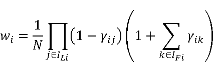
により表されるwiとし、各第iチャネルについての正規化された重みを
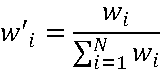
により表されるw'iとして、

によりダウンミックス信号の各サンプルxM(t)を得るダウンミックスステップと、
を有することを特徴とする。
符号化処理などの信号処理の対象となる2チャネルの音信号は、ある空間に配置された左チャネル用のマイクロホンと右チャネル用のマイクロホンのそれぞれで収音した音をAD変換して得られたディジタルの音信号であることが多い。この場合には、符号化処理などの信号処理をする装置に入力されるのは、当該空間に配置した左チャネル用のマイクロホンで収音した音をAD変換して得られたディジタルの音信号である左チャネル入力音信号と、当該空間に配置した右チャネル用のマイクロホンで収音した音をAD変換して得られたディジタルの音信号である右チャネル入力音信号である。この左チャネル入力音信号と右チャネル入力音信号には、当該空間に存在する各音源が発した音が、音源から左チャネル用のマイクロホンへの到達時間と、音源から右チャネル用のマイクロホンへの到達時間と、の差(いわゆる到来時間差)が与えられた状態で含まれている。
まず、第1実施形態の第1例の音信号ダウンミックス装置について説明する。第1例の音信号ダウンミックス装置401は、図1に示す通り、左右関係情報推定部183とダウンミックス部112を含む。音信号ダウンミックス装置401は、例えば20msの所定の時間長のフレーム単位で、入力された2チャネルステレオの時間領域の音信号から、後述するダウンミックス信号を得て出力する。音信号ダウンミックス装置401に入力されるのは2チャネルステレオの時間領域の音信号であり、例えば、音声や音楽などの音を2個のマイクロホンそれぞれで収音してAD変換して得られたディジタルの音信号、前述したディジタルの音信号を符号化/復号して得たディジタルの復号音信号、前述したディジタルの音信号を信号処理して得たディジタルの信号処理済みの音信号、であり、左チャネル入力音信号と右チャネル入力音信号から成る。音信号ダウンミックス装置401が得た時間領域のモノラルの音信号であるダウンミックス信号は、少なくともダウンミックス信号を符号化する符号化装置や少なくともダウンミックス信号を信号処理する信号処理装置に入力される。フレーム当たりのサンプル数をTとすると、音信号ダウンミックス装置401にはフレーム単位で左チャネル入力音信号xL(1), xL(2), ..., xL(T)と右チャネル入力音信号xR(1), xR(2), ..., xR(T)が入力され、音信号ダウンミックス装置401はフレーム単位でダウンミックス信号xM(1), xM(2), ..., xM(T)を得て出力する。ここで、Tは正の整数であり、例えば、フレーム長が20msであり、サンプリング周波数が32kHzであれば、Tは640である。第1例の音信号ダウンミックス装置401は、各フレームについて、図2に例示するステップS183とステップS112の処理を行う。
左右関係情報推定部183には、音信号ダウンミックス装置401に入力された左チャネル入力音信号と、音信号ダウンミックス装置401に入力された右チャネル入力音信号と、が入力される。左右関係情報推定部183は、左チャネル入力音信号と右チャネル入力音信号から、左右相関値γと、先行チャネル情報と、を得て出力する(ステップS183)。


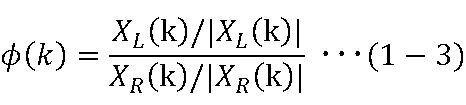
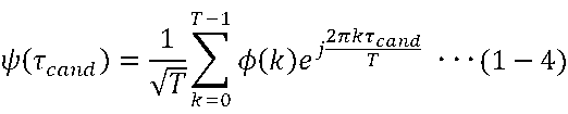

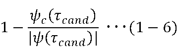
ダウンミックス部112には、音信号ダウンミックス装置401に入力された左チャネル入力音信号と、音信号ダウンミックス装置401に入力された右チャネル入力音信号と、左右関係情報推定部183が出力した左右相関値γと、左右関係情報推定部183が出力した先行チャネル情報と、が入力される。ダウンミックス部112は、ダウンミックス信号に、左チャネル入力音信号と右チャネル入力音信号のうちの先行しているチャネルの入力音信号のほうが、左右相関値γが大きいほど大きく含まれるように、左チャネル入力音信号と右チャネル入力音信号を重み付け平均してダウンミックス信号を得て出力する(ステップS112)。
例えば、音信号ダウンミックス装置とは別の装置が左チャネル入力音信号と右チャネル入力音信号をステレオ符号化処理する場合、左チャネル入力音信号と右チャネル入力音信号が音信号ダウンミックス装置とは別の装置によるステレオ復号処理により得られた信号である場合、などにおいては、左右関係情報推定部183が得るのと同じ左右相関値γと先行チャネル情報の何れか一方または両方が音信号ダウンミックス装置とは別装置で得られている場合がある。左右相関値γと先行チャネル情報の何れか一方または両方が別装置で得られている場合は、音信号ダウンミックス装置には、別装置で得た左右相関値γと先行チャネル情報の何れか一方または両方が入力されるようにして、左右関係情報推定部183は、音信号ダウンミックス装置に入力されなかった左右相関値γまたは先行チャネル情報を得るようにすればよい。以下、左右相関値γと先行チャネル情報の何れか一方または両方が外部から入力されることを想定した音信号ダウンミックス装置の例を第2例として、第1例と異なる点を中心に説明する。
左右関係情報取得部185は、左チャネル入力音信号と右チャネル入力音信号の相関の大きさを表す値である左右相関値γと、左チャネル入力音信号と右チャネル入力音信号のどちらが先行しているかを表す情報である先行チャネル情報と、を得て出力する(ステップS185)。
チャネル数が3以上の場合であっても、各チャネルの入力音信号とダウンミックス信号との関係を第1実施形態の音信号ダウンミックス装置401、405と同様にすることで、符号化処理などの信号処理に有用なモノラル信号を得ることができる。この形態を第2実施形態として説明する。
まず、第2実施形態の第1例の音信号ダウンミックス装置について説明する。第1例の音信号ダウンミックス装置406は、図5に示す通り、チャネル間関係情報推定部186とダウンミックス部116を含む。音信号ダウンミックス装置406は、例えば20msの所定の時間長のフレーム単位で、入力されたNチャネルステレオの時間領域の音信号から、後述するダウンミックス信号を得て出力する。チャネル数Nは2以上の整数である。ただし、チャネル数が2の場合には第1実施形態の音信号ダウンミックス装置を用いればよいので、第2実施形態の音信号ダウンミックス装置が特に有用なのはNが3以上の整数の場合である。音信号ダウンミックス装置406に入力されるのはN個のチャネルの時間領域の音信号であり、例えば、音声や音楽などの音をN個のマイクロホンそれぞれで収音してAD変換して得られたディジタルの音信号、複数の地点それぞれで収音してAD変換して得られた1チャネルまたは複数個のチャネルのディジタルの音信号をそのまままたは適宜混合してN個のチャネルにしたディジタルの音信号、前述した各ディジタルの音信号を符号化・復号して得たディジタルの復号音信号、前述した各ディジタルの音信号を信号処理して得たディジタルの信号処理済みの音信号、である。音信号ダウンミックス装置406が得た時間領域のモノラルの音信号であるダウンミックス信号は、少なくともダウンミックス信号を符号化する符号化装置や少なくともダウンミックス信号を信号処理する信号処理装置に入力される。音信号ダウンミックス装置406には、フレーム単位でN個のチャネルの入力音信号が入力され、音信号ダウンミックス装置406は、フレーム単位でダウンミックス信号を得て出力する。以下では、フレーム当たりのサンプル数をTとして説明する。Tは正の整数であり、例えば、フレーム長が20msであり、サンプリング周波数が32kHzであれば、Tは640である。第1例の音信号ダウンミックス装置406は、各フレームについて、図6に例示するステップS186とステップS116の処理を行う。
チャネル間関係情報推定部186には、音信号ダウンミックス装置406に入力されたN個のチャネルの入力音信号が入力される。チャネル間関係情報推定部186は、入力されたN個のチャネルの入力音信号から、チャネル間相関値と、先行チャネル情報と、を得て出力する(ステップS186)。チャネル間相関値と先行チャネル情報は、N個のチャネルの入力音信号におけるチャネル間の関係を表す情報であるので、チャネル間関係情報であるともいえる。
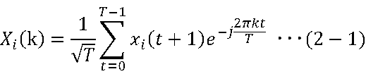

ダウンミックス部116には、音信号ダウンミックス装置406に入力されたN個のチャネルの入力音信号と、チャネル間関係情報推定部186が出力した上述した(N×(N-1))/2通りのnとmの組合せそれぞれについてのチャネル間相関値γnm(すなわち、N個のチャネルに含まれる2個のチャネルによる組合せそれぞれについてのチャネル間相関値)と、チャネル間関係情報推定部186が出力した上述した(N×(N-1))/2通りのnとmの組合せそれぞれについての先行チャネル情報INFOnm(すなわち、N個のチャネルに含まれる2個のチャネルによる組合せそれぞれについての先行チャネル情報)と、が入力される。ダウンミックス部116は、各チャネルの入力音信号に、当該チャネルより先行している各チャネルの入力音信号との相関が大きいほど小さく、当該チャネルより後行している各チャネルの入力音信号との相関が大きいほど大きい重みを与えて、N個のチャネルの入力音信号を重み付け加算してダウンミックス信号を得て出力する(ステップS116)。
各チャネルのチャネル番号(チャネルのインデックス)をiとし、第iチャネルの入力音信号をxi(1), xi(2), ..., xi(T)とし、ダウンミックス信号をxM(1), xM(2), ..., xM(T)として、ダウンミックス部116の具体例1を説明する。具体例1では、チャネル間相関値は、チャネル間関係情報推定部186の説明箇所で上述した例の相関係数の絶対値や正規化された値のように、0以上1以下の値であるとする。またここで、Mはチャネルの番号ではなく、ダウンミックス信号がモノラルの信号であることを意図した添え字である。ダウンミックス部116は、例えば下記のステップS116-1からステップS116-3の処理を行うことにより、ダウンミックス信号を得る。ダウンミックス部116は、まず、各第iチャネルについて、ダウンミックス部116に入力された先行チャネル情報INFOnmのうちの当該第iチャネルを含む(N-1)通りの2個のチャネルによる組合せの先行チャネル情報から、当該第iチャネルに対して先行しているチャネルのチャネル番号の集合ILiと、当該第iチャネルに対して後行しているチャネルのチャネル番号の集合IFiと、を得る(ステップS116-1)。ダウンミックス部116は、次に、各第iチャネルについて、ダウンミックス部116に入力されたチャネル間相関値γnmのうちの当該第iチャネルを含む(N-1)通りの2個のチャネルによる組合せのチャネル間相関値と、当該第iチャネルに対して先行しているチャネルのチャネル番号の集合ILiと、当該第iチャネルに対して後行しているチャネルのチャネル番号の集合IFiと、を用いて下記の式(2-3)により当該第iチャネルの重みwiを得る(ステップS116-2)。
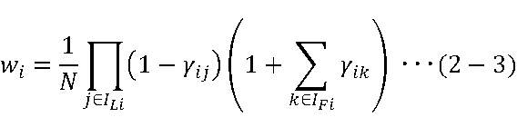
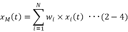


具体例1のステップS116-1でダウンミックス部116が得た重みwiの全チャネルの合計値は1とならないことあるので、ダウンミックス部116は、重みの全チャネルの合計値が1となるように各第iチャネルの重みwiを正規化して得た値を式(2-4)の重みwiに代えて用いたり、重みの全チャネルの合計値が1となるように重みwiを正規化することを含むように式(2-4)を変形した式を用いたりすることにより、ダウンミックス信号を得るようにしてもよい。この例をダウンミックス部116の具体例2として、具体例1と異なる点を説明する。

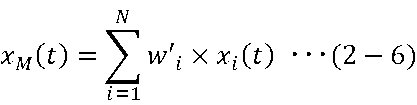
例えば、音信号ダウンミックス装置とは別の装置がN個のチャネルの入力音信号をステレオ符号化処理する場合、N個のチャネルの入力音信号が音信号ダウンミックス装置とは別の装置によるステレオ復号処理により得られた信号である場合、などにおいては、チャネル間関係情報推定部186が得るのと同じチャネル間相関値γnmと先行チャネル情報INFOnmの何れかまたは全てが音信号ダウンミックス装置とは別装置で得られている場合がある。チャネル間相関値γnmと先行チャネル情報INFOnmの何れかまたは全てが別装置で得られている場合は、音信号ダウンミックス装置には、別装置で得たチャネル間相関値γnmと先行チャネル情報INFOnmの何れかまたは全てが入力されるようにして、チャネル間関係情報推定部186は、音信号ダウンミックス装置に入力されなかったチャネル間相関値γnmや先行チャネル情報INFOnmを得るようにすればよい。以下、チャネル間相関値γnmと先行チャネル情報INFOnmの何れかまたは全てが外部から入力されることを想定した音信号ダウンミックス装置の例を第2例として、第1例と異なる点を中心に説明する。
チャネル間関係情報取得部187は、N個のチャネルに含まれる2個のチャネルによる組合せそれぞれについての相関の大きさを表す値であるチャネル間相関値γnmと、N個のチャネルに含まれる2個のチャネルによる組合せそれぞれについての、同じ音信号が2個のチャネルの入力音信号のどちらに先に含まれているかを表す情報である先行チャネル情報INFOnmと、を得て出力する(ステップS187)。
第2実施形態のチャネル間関係情報推定部186は、N個のチャネルに含まれる2個のチャネルによる組合せそれぞれについてチャネル間相関値γnmと先行チャネル情報INFOnmを得る必要がある。N個のチャネルに含まれる2個のチャネルによる組合せは、(N×(N-1))/2通りあることから、第2実施形態のチャネル間関係情報推定部186の説明箇所で例示した方法でチャネル間相関値γnmと先行チャネル情報INFOnmを得ると、チャネル数が多い場合には演算処理量が課題となることがある。第3実施形態では、チャネル間関係情報推定部186よりも演算処理量が少ない方法で近似的にチャネル間相関値γnmと先行チャネル情報INFOnmを得るチャネル間関係情報推定処理を含む音信号ダウンミックス装置について説明する。第3実施形態のダウンミックス処理は第2実施形態と同様である。
γ13 = γ12×γ23 = 1×0 = 0
γ14 = γ12×γ23×γ34 = 1×0×1 = 0
γ15 = γ12×γ23×γ34×γ45 = 1×0×1×1 = 0
γ16 = γ12×γ23×γ34×γ45×γ56 = 1×0×1×1×1 = 0
γ24 = γ23×γ34 = 0×1 = 0
γ25 = γ23×γ34×γ45 = 0×1×1 = 0
γ26 = γ23×γ34×γ45×γ56 = 0×1×1×1 = 0
γ35 = γ34×γ45 = 1×1 = 1
γ36 = γ34×γ45×γ56 = 1×1×1 = 1
γ46 = γ45×γ56 = 1×1 = 1
τ13 = τ12+τ23
τ14 = τ12+τ23+τ34
τ15 = τ12+τ23+τ34+τ45
τ16 = τ12+τ23+τ34+τ45+τ56
τ24 = τ23+τ34
τ25 = τ23+τ34+τ45
τ26 = τ23+τ34+τ45+τ56
τ35 = τ34+τ45
τ36 = τ34+τ45+τ56
τ46 = τ45+τ56
第3実施形態の第1例の音信号ダウンミックス装置について説明する。第1例の音信号ダウンミックス装置408は、図5に示す通り、チャネル間関係情報推定部188とダウンミックス部116を含む。第1例の音信号ダウンミックス装置408は、各フレームについて、図6に例示するステップS188とステップS116の処理を行う。ダウンミックス部116とステップS116は第2実施形態の第1例と同じであるので、以下では、第2実施形態の第1例と異なるチャネル間関係情報推定部188とステップS188について説明する。音信号ダウンミックス装置408に入力されるのは第2実施形態の第1例の音信号ダウンミックス装置408と同様にN個のチャネルの時間領域の音信号であり、音信号ダウンミックス装置408が得て出力するのは第2実施形態の第1例の音信号ダウンミックス装置406と同様に時間領域のモノラルの音信号であるダウンミックス信号である。
チャネル間関係情報推定部188には、音信号ダウンミックス装置408に入力されたN個のチャネルの入力音信号が入力される。第2実施形態ではチャネル数Nは2以上の整数であったが、チャネル数Nが2である場合には入力音信号の波形が同一または類似するチャネルの間に入力音信号の波形が大きく異なるチャネルが存在することはないので、第3実施形態ではチャネル数Nは3以上の整数である。チャネル間関係情報推定部188は、例えば、図11に示す通り、チャネル並び替え部1881と隣接チャネル間関係情報推定部1882とチャネル間関係情報補完部1883を含む。チャネル間関係情報推定部188は、チャネル間関係情報推定部188は、例えば、各フレームについて、図12に例示するステップS1881とステップS1882とステップS1883の処理を行う(ステップS188)。
チャネル並び替え部1881は、例えば、第1チャネルから順に、残りのチャネルのうちの時間差を揃えたときに入力音信号の波形の類似の度合いが最も高いチャネルが隣接するチャネルとなるように、逐次的に並び替えを行って、N個のチャネルの並び替え後の信号である第1並び替え済入力音信号から第N並び替え済入力音信号と、各並び替え済入力音信号が音信号ダウンミックス装置408に入力されたときのチャネル番号(すなわち、入力音信号のチャネル番号)である第1原チャネル情報c1から第N原チャネル情報cNと、を得て出力する(ステップS1881A)。チャネル並び替え部1881は、時間差を揃えたときの波形の類似の度合いとしては、時間差を揃えたときの2つのチャネルの入力音信号間の距離の近さを表す値、時間差を揃えたときの2つのチャネルの入力音信号の内積を2つのチャネルの入力音信号のエネルギーの相乗平均で除算値などの相関の大きさを表す値、などを用いればよい。
隣接チャネル間関係情報推定部1882には、第1並び替え済入力音信号から第N並び替え済入力音信号までのN個の並び替え済入力音信号が入力される。隣接チャネル間関係情報推定部1882は、N個の並び替え済入力音信号のうちの並び替え後のチャネル番号が隣接する2個の並び替え後のチャネルによる組合せそれぞれについてのチャネル間相関値とチャネル間時間差と、を得て出力する(ステップS1882)。

チャネル間関係情報補完部1883には、隣接チャネル間関係情報推定部1882が出力した、並び替え後のチャネル番号が隣接する2個の並び替え後のチャネルによる組合せそれぞれについての、チャネル間相関値とチャネル間時間差と、チャネル並び替え部1881が出力した、並び替え後の各チャネルについての原チャネル情報と、が入力される。チャネル間関係情報補完部1883は、下記のステップS1883-1からステップS1883-5の処理を行うことで、2個のチャネルによる組合せ全て(すなわち、並び替え元の2個のチャネルによる組合せ全て)についてのチャネル間相関値と先行チャネル情報を得て出力する(ステップS1883)。
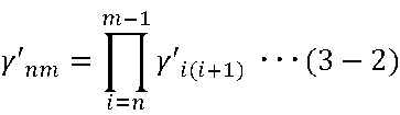
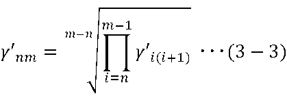
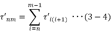
第2実施形態の第2例のチャネル間関係情報推定部186に代えて、第3実施形態の第1例のチャネル間関係情報推定部188を用いてもよい。この場合には、音信号ダウンミックス装置407のチャネル間関係情報取得部187はチャネル間関係情報推定部186に代えてチャネル間関係情報推定部188を備えて、チャネル間関係情報取得部187は、チャネル間関係情報推定部186をチャネル間関係情報推定部188と読み替えた動作をすればよい。この場合の音信号ダウンミックス装置407の装置構成は図7に例示する通りであり、音信号ダウンミックス装置407の処理の流れは図8に例示する通りである。
音信号を符号化する符号化装置に上述した第2実施形態と第3実施形態の音信号ダウンミックス装置を音信号ダウンミックス部として含んでもよく、この形態を第4実施形態として説明する。
第4実施形態の音信号符号化装置106は、図13に示す通り、音信号ダウンミックス部407と符号化部196を含む。第4実施形態の音信号符号化装置106は、例えば20msの所定の時間長のフレーム単位で、入力されたNチャネルステレオの時間領域の音信号を符号化して、音信号符号を得て出力する。音信号符号化装置106に入力されるNチャネルステレオの時間領域の音信号は、例えば、音声や音楽などの音をN個のマイクロホンそれぞれで収音してAD変換して得られたディジタルの音声信号又は音響信号であり、第1チャネル入力音信号から第Nチャネル入力音信号のN個の入力音信号からなる。符号化装置が出力する音信号符号は復号装置へ入力される。第4実施形態の音信号符号化装置105は、各フレームについて、図14に例示するステップS407とステップS196の処理を行う。以下、第4実施形態の音信号符号化装置106について、第2実施形態と第3実施形態の説明を適宜参照して説明する。
音信号ダウンミックス部407は、音信号符号化装置106に入力された第1チャネル入力音信号から第Nチャネル入力音信号のN個の入力音信号からダウンミックス信号を得て出力する(ステップS407)。音信号ダウンミックス部407は、第2実施形態または第3実施形態の音信号ダウンミックス装置407と同様であり、チャネル間関係情報取得部187とダウンミックス部116を含む。チャネル間関係情報取得部187は上述したステップS187を行い、ダウンミックス部116は上述したステップS116を行う。すなわち、音信号符号化装置106は、第2実施形態または第3実施形態の音信号ダウンミックス装置407を音信号ダウンミックス部407として含んでおり、第2実施形態または第3実施形態の音信号ダウンミックス装置407の処理をステップS407として行う。
符号化部196には、音信号ダウンミックス部407が出力したダウンミックス信号が少なくとも入力される。符号化部196は、入力されたダウンミックス信号を少なくとも符号化して音信号符号を得て出力する(ステップS196)。符号化部196は、第1チャネル入力音信号から第Nチャネル入力音信号のN個の入力音信号も符号化してもよく、この符号化で得た符号も音信号符号に含めて出力してもよい。この場合には、図13に破線で示すように、符号化部196には第1チャネル入力音信号から第Nチャネル入力音信号のN個の入力音信号も入力される。
音信号を信号処理する信号処理装置に上述した第2実施形態と第3実施形態の音信号ダウンミックス装置を音信号ダウンミックス部として含んでもよく、この形態を第5実施形態として説明する。
第5実施形態の音信号処理装置306は、図15に示す通り、音信号ダウンミックス部407と信号処理部316を含む。第5実施形態の音信号処理装置306は、例えば20msの所定の時間長のフレーム単位で、入力されたNチャネルステレオの時間領域の音信号を信号処理して、信号処理結果を得て出力する。音信号処理装置306に入力されるNチャネルステレオの時間領域の音信号は、例えば、音声や音楽などの音をN個のマイクロホンそれぞれで収音してAD変換して得られたディジタルの音声信号又は音響信号であり、また例えば、当該ディジタルの音声信号又は音響信号を加工して得たディジタルの音声信号又は音響信号であり、また例えば、ステレオ復号装置がステレオ符号を復号して得たディジタルの復号音声信号又は復号音響信号であり、第1チャネル入力音信号から第Nチャネル入力音信号のN個の入力音信号からなる。第5実施形態の音信号処理装置306は、各フレームについて、図16に例示するステップS407とステップS316の処理を行う。以下、第5実施形態の音信号処理装置306について、第2実施形態と第3実施形態の説明を適宜参照して説明する。
音信号ダウンミックス部407は、音信号処理装置306に入力された第1チャネル入力音信号から第Nチャネル入力音信号のN個の入力音信号からダウンミックス信号を得て出力する(ステップS407)。音信号ダウンミックス部407は、第2実施形態または第3実施形態の音信号ダウンミックス装置407と同様であり、チャネル間関係情報取得部187とダウンミックス部116を含む。チャネル間関係情報取得部187は上述したステップS187を行い、ダウンミックス部116は上述したステップS116を行う。すなわち、音信号処理装置306は、第2実施形態または第3実施形態の音信号ダウンミックス装置407を音信号ダウンミックス部407として含んでおり、第2実施形態または第3実施形態の音信号ダウンミックス装置407の処理をステップS407として行う。
信号処理部316には、音信号ダウンミックス部407が出力したダウンミックス信号が少なくとも入力される。信号処理部316は、入力されたダウンミックス信号を少なくとも信号処理して信号処理結果を得て出力する(ステップS316)。信号処理部316は、第1チャネル入力音信号から第Nチャネル入力音信号のN個の入力音信号も信号処理して信号処理結果を得てもよく、この場合には、図15に破線で示すように、信号処理部316には第1チャネル入力音信号から第Nチャネル入力音信号のN個の入力音信号も入力され、信号処理部316は、例えば、各チャネルの入力音信号に対してダウンミックス信号を用いた信号処理を行って各チャネルの出力音信号を信号処理結果として得る。
上述した各音信号ダウンミックス装置と音信号符号化装置と音信号処理装置との各部の処理をコンピュータにより実現してもよく、この場合は各装置が有すべき機能の処理内容はプログラムによって記述される。そして、このプログラムを図17に示すコンピュータ1000の記憶部1020に読み込ませ、演算処理部1010、入力部1030、出力部1040などに動作させることにより、上記各装置における各種の処理機能がコンピュータ上で実現される。
Claims (8)
- N個(Nは3以上の整数)のチャネルの入力音信号からモノラルの音信号であるダウンミックス信号を得る音信号ダウンミックス方法であって、
前記N個のチャネルに含まれる2個のチャネルによる組合せのそれぞれについての、2個のチャネルの入力音信号間の相関の大きさを表す0以上1以下の値であるチャネル間相関値と、2個のチャネルの入力音信号のどちらが先行しているかを表す情報である先行チャネル情報と、を得るチャネル間関係情報取得ステップと、
サンプル番号をtとし、iが1からNまでの各第iチャネルの前記入力音信号の各サンプルをxi(t)とし、前記ダウンミックス信号の各サンプルをxM(t)とし、
各第iチャネルについての、当該第iチャネルに対して先行しているチャネルのチャネル番号の集合をILiとし、
各第iチャネルについての、当該第iチャネルに対して後行しているチャネルのチャネル番号の集合をIFiとし、
各第iチャネルについての、当該第iチャネルと、当該第iチャネルに対して先行している各チャネルjと、の組合せそれぞれについての、前記チャネル間相関値をγijとし、
各第iチャネルについての、当該第iチャネルと、当該第iチャネルに対して後行している各チャネルkと、の組合せそれぞれについての、前記チャネル間相関値をγikとし、
各第iチャネルについての重みを

により表されるwiとし、
各第iチャネルについての正規化された重みを
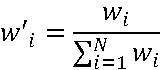
により表されるw'iとして、
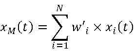
により前記ダウンミックス信号の各サンプルxM(t)を得るダウンミックスステップと、
を含むことを特徴とする音信号ダウンミックス方法。 - 請求項1に記載の音信号ダウンミックス方法を音信号ダウンミックスステップとして含み、
前記ダウンミックスステップが得た前記ダウンミックス信号を符号化してモノラル符号を得るモノラル符号化ステップと、
前記N個チャネルの入力音信号を符号化してステレオ符号を得るステレオ符号化ステップと、
を更に含む
ことを特徴とする音信号符号化方法。 - N個(Nは3以上の整数)のチャネルの入力音信号からモノラルの音信号であるダウンミックス信号を得る音信号ダウンミックス装置であって、
前記N個のチャネルに含まれる2個のチャネルによる組合せのそれぞれについての、2個のチャネルの入力音信号間の相関の大きさを表す0以上1以下の値であるチャネル間相関値と、2個のチャネルの入力音信号のどちらが先行しているかを表す情報である先行チャネル情報と、を得るチャネル間関係情報取得部と、
サンプル番号をtとし、iが1からNまでの各第iチャネルの前記入力音信号の各サンプルをxi(t)とし、前記ダウンミックス信号の各サンプルをxM(t)とし、
各第iチャネルについての、当該第iチャネルに対して先行しているチャネルのチャネル番号の集合をILiとし、
各第iチャネルについての、当該第iチャネルに対して後行しているチャネルのチャネル番号の集合をIFiとし、
各第iチャネルについての、当該第iチャネルと、当該第iチャネルに対して先行している各チャネルjと、の組合せそれぞれについての、前記チャネル間相関値をγijとし、
各第iチャネルについての、当該第iチャネルと、当該第iチャネルに対して後行している各チャネルkと、の組合せそれぞれについての、前記チャネル間相関値をγikとし、
各第iチャネルについての重みを

により表されるwiとし、
各第iチャネルについての正規化された重みを

により表されるw'iとして、
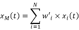
により前記ダウンミックス信号の各サンプルxM(t)を得るダウンミックス部と、
を含むことを特徴とする音信号ダウンミックス装置。 - 請求項3に記載の音信号ダウンミックス装置を音信号ダウンミックス部として含み、
前記ダウンミックス部が得た前記ダウンミックス信号を符号化してモノラル符号を得るモノラル符号化部と、
前記N個チャネルの入力音信号を符号化してステレオ符号を得るステレオ符号化部と、
を更に含む
ことを特徴とする音信号符号化装置。 - 請求項1に記載の音信号ダウンミックス方法の各ステップの処理をコンピュータに実行させるためのプログラム。
- 請求項2に記載の音信号符号化方法の各ステップの処理をコンピュータに実行させるためのプログラム。
- 請求項1に記載の音信号ダウンミックス方法の各ステップの処理をコンピュータに実行させるためのプログラムを記録したコンピュータ読み取り可能な記録媒体。
- 請求項2に記載の音信号符号化方法の各ステップの処理をコンピュータに実行させるためのプログラムを記録したコンピュータ読み取り可能な記録媒体。
Priority Applications (2)
| Application Number | Priority Date | Filing Date | Title |
|---|---|---|---|
| JP2022505843A JP7380834B2 (ja) | 2020-03-09 | 2021-02-08 | 音信号ダウンミックス方法、音信号符号化方法、音信号ダウンミックス装置、音信号符号化装置、プログラム及び記録媒体 |
| US17/909,677 US12315520B2 (en) | 2020-03-09 | 2021-02-08 | Sound signal downmixing method, sound signal coding method, sound signal downmixing apparatus, sound signal coding apparatus, program and recording medium |
Applications Claiming Priority (6)
| Application Number | Priority Date | Filing Date | Title |
|---|---|---|---|
| JPPCT/JP2020/010080 | 2020-03-09 | ||
| PCT/JP2020/010081 WO2021181473A1 (ja) | 2020-03-09 | 2020-03-09 | 音信号符号化方法、音信号復号方法、音信号符号化装置、音信号復号装置、プログラム及び記録媒体 |
| JPPCT/JP2020/010081 | 2020-03-09 | ||
| PCT/JP2020/010080 WO2021181472A1 (ja) | 2020-03-09 | 2020-03-09 | 音信号符号化方法、音信号復号方法、音信号符号化装置、音信号復号装置、プログラム及び記録媒体 |
| PCT/JP2020/041216 WO2021181746A1 (ja) | 2020-03-09 | 2020-11-04 | 音信号ダウンミックス方法、音信号符号化方法、音信号ダウンミックス装置、音信号符号化装置、プログラム及び記録媒体 |
| JPPCT/JP2020/041216 | 2020-11-04 |
Publications (1)
| Publication Number | Publication Date |
|---|---|
| WO2021181975A1 true WO2021181975A1 (ja) | 2021-09-16 |
Family
ID=77671498
Family Applications (4)
| Application Number | Title | Priority Date | Filing Date |
|---|---|---|---|
| PCT/JP2020/041216 Ceased WO2021181746A1 (ja) | 2020-03-09 | 2020-11-04 | 音信号ダウンミックス方法、音信号符号化方法、音信号ダウンミックス装置、音信号符号化装置、プログラム及び記録媒体 |
| PCT/JP2021/004640 Ceased WO2021181975A1 (ja) | 2020-03-09 | 2021-02-08 | 音信号ダウンミックス方法、音信号符号化方法、音信号ダウンミックス装置、音信号符号化装置、プログラム及び記録媒体 |
| PCT/JP2021/004642 Ceased WO2021181977A1 (ja) | 2020-03-09 | 2021-02-08 | 音信号ダウンミックス方法、音信号符号化方法、音信号ダウンミックス装置、音信号符号化装置、プログラム及び記録媒体 |
| PCT/JP2021/004641 Ceased WO2021181976A1 (ja) | 2020-03-09 | 2021-02-08 | 音信号ダウンミックス方法、音信号符号化方法、音信号ダウンミックス装置、音信号符号化装置、プログラム及び記録媒体 |
Family Applications Before (1)
| Application Number | Title | Priority Date | Filing Date |
|---|---|---|---|
| PCT/JP2020/041216 Ceased WO2021181746A1 (ja) | 2020-03-09 | 2020-11-04 | 音信号ダウンミックス方法、音信号符号化方法、音信号ダウンミックス装置、音信号符号化装置、プログラム及び記録媒体 |
Family Applications After (2)
| Application Number | Title | Priority Date | Filing Date |
|---|---|---|---|
| PCT/JP2021/004642 Ceased WO2021181977A1 (ja) | 2020-03-09 | 2021-02-08 | 音信号ダウンミックス方法、音信号符号化方法、音信号ダウンミックス装置、音信号符号化装置、プログラム及び記録媒体 |
| PCT/JP2021/004641 Ceased WO2021181976A1 (ja) | 2020-03-09 | 2021-02-08 | 音信号ダウンミックス方法、音信号符号化方法、音信号ダウンミックス装置、音信号符号化装置、プログラム及び記録媒体 |
Country Status (1)
| Country | Link |
|---|---|
| WO (4) | WO2021181746A1 (ja) |
Families Citing this family (3)
| Publication number | Priority date | Publication date | Assignee | Title |
|---|---|---|---|---|
| JP7803346B2 (ja) * | 2021-09-01 | 2026-01-21 | Ntt株式会社 | 音信号ダウンミックス方法、音信号符号化方法、音信号ダウンミックス装置、音信号符号化装置、プログラム |
| JPWO2024142359A1 (ja) * | 2022-12-28 | 2024-07-04 | ||
| WO2024142360A1 (ja) * | 2022-12-28 | 2024-07-04 | 日本電信電話株式会社 | 音信号処理装置、音信号処理方法、プログラム |
Citations (6)
| Publication number | Priority date | Publication date | Assignee | Title |
|---|---|---|---|---|
| JP2010525403A (ja) * | 2007-04-26 | 2010-07-22 | ドルビー インターナショナル アクチボラゲット | 出力信号の合成装置及び合成方法 |
| WO2010097748A1 (en) * | 2009-02-27 | 2010-09-02 | Koninklijke Philips Electronics N.V. | Parametric stereo encoding and decoding |
| WO2010140350A1 (ja) * | 2009-06-02 | 2010-12-09 | パナソニック株式会社 | ダウンミックス装置、符号化装置、及びこれらの方法 |
| JP2011522472A (ja) * | 2008-05-23 | 2011-07-28 | コーニンクレッカ フィリップス エレクトロニクス エヌ ヴィ | パラメトリックステレオアップミクス装置、パラメトリックステレオデコーダ、パラメトリックステレオダウンミクス装置、及びパラメトリックステレオエンコーダ |
| JP2018533056A (ja) * | 2015-09-25 | 2018-11-08 | ヴォイスエイジ・コーポレーション | ステレオ音声信号をプライマリチャンネルおよびセカンダリチャンネルに時間領域ダウンミックスするために左チャンネルと右チャンネルとの間の長期相関差を使用する方法およびシステム |
| JP2019536112A (ja) * | 2016-11-08 | 2019-12-12 | フラウンホファー ゲセルシャフト ツール フェールデルンク ダー アンゲヴァンテン フォルシュンク エー.ファオ. | サイドゲインおよび残余ゲインを使用してマルチチャネル信号を符号化または復号するための装置および方法 |
-
2020
- 2020-11-04 WO PCT/JP2020/041216 patent/WO2021181746A1/ja not_active Ceased
-
2021
- 2021-02-08 WO PCT/JP2021/004640 patent/WO2021181975A1/ja not_active Ceased
- 2021-02-08 WO PCT/JP2021/004642 patent/WO2021181977A1/ja not_active Ceased
- 2021-02-08 WO PCT/JP2021/004641 patent/WO2021181976A1/ja not_active Ceased
Patent Citations (6)
| Publication number | Priority date | Publication date | Assignee | Title |
|---|---|---|---|---|
| JP2010525403A (ja) * | 2007-04-26 | 2010-07-22 | ドルビー インターナショナル アクチボラゲット | 出力信号の合成装置及び合成方法 |
| JP2011522472A (ja) * | 2008-05-23 | 2011-07-28 | コーニンクレッカ フィリップス エレクトロニクス エヌ ヴィ | パラメトリックステレオアップミクス装置、パラメトリックステレオデコーダ、パラメトリックステレオダウンミクス装置、及びパラメトリックステレオエンコーダ |
| WO2010097748A1 (en) * | 2009-02-27 | 2010-09-02 | Koninklijke Philips Electronics N.V. | Parametric stereo encoding and decoding |
| WO2010140350A1 (ja) * | 2009-06-02 | 2010-12-09 | パナソニック株式会社 | ダウンミックス装置、符号化装置、及びこれらの方法 |
| JP2018533056A (ja) * | 2015-09-25 | 2018-11-08 | ヴォイスエイジ・コーポレーション | ステレオ音声信号をプライマリチャンネルおよびセカンダリチャンネルに時間領域ダウンミックスするために左チャンネルと右チャンネルとの間の長期相関差を使用する方法およびシステム |
| JP2019536112A (ja) * | 2016-11-08 | 2019-12-12 | フラウンホファー ゲセルシャフト ツール フェールデルンク ダー アンゲヴァンテン フォルシュンク エー.ファオ. | サイドゲインおよび残余ゲインを使用してマルチチャネル信号を符号化または復号するための装置および方法 |
Also Published As
| Publication number | Publication date |
|---|---|
| WO2021181977A1 (ja) | 2021-09-16 |
| WO2021181746A1 (ja) | 2021-09-16 |
| WO2021181976A1 (ja) | 2021-09-16 |
Similar Documents
| Publication | Publication Date | Title |
|---|---|---|
| WO2021181974A1 (ja) | 音信号ダウンミックス方法、音信号符号化方法、音信号ダウンミックス装置、音信号符号化装置、プログラム及び記録媒体 | |
| JP7544139B2 (ja) | 音信号高域補償方法、音信号後処理方法、音信号復号方法、これらの装置、プログラム、および記録媒体 | |
| WO2022097243A1 (ja) | 音信号高域補償方法、音信号後処理方法、音信号復号方法、これらの装置、プログラム、および記録媒体 | |
| WO2021181977A1 (ja) | 音信号ダウンミックス方法、音信号符号化方法、音信号ダウンミックス装置、音信号符号化装置、プログラム及び記録媒体 | |
| WO2012070370A1 (ja) | 音声符号化装置、方法およびプログラム、並びに、音声復号装置、方法およびプログラム | |
| JP7491393B2 (ja) | 音信号精製方法、音信号復号方法、これらの装置、プログラム及び記録媒体 | |
| JP7517459B2 (ja) | 音信号高域補償方法、音信号後処理方法、音信号復号方法、これらの装置、プログラム、および記録媒体 | |
| JP7491394B2 (ja) | 音信号精製方法、音信号復号方法、これらの装置、プログラム及び記録媒体 | |
| JP7537512B2 (ja) | 音信号精製方法、音信号復号方法、これらの装置、プログラム及び記録媒体 | |
| JP7537511B2 (ja) | 音信号精製方法、音信号復号方法、これらの装置、プログラム及び記録媒体 | |
| JP7491395B2 (ja) | 音信号精製方法、音信号復号方法、これらの装置、プログラム及び記録媒体 | |
| JP7517458B2 (ja) | 音信号高域補償方法、音信号後処理方法、音信号復号方法、これらの装置、プログラム、および記録媒体 | |
| JP7517460B2 (ja) | 音信号高域補償方法、音信号後処理方法、音信号復号方法、これらの装置、プログラム、および記録媒体 | |
| JP2026001181A (ja) | 音信号ダウンミックス方法、音信号ダウンミックス装置、プログラム | |
| JP7521595B2 (ja) | 音信号精製方法、音信号復号方法、これらの装置、プログラム及び記録媒体 | |
| JP7521596B2 (ja) | 音信号精製方法、音信号復号方法、これらの装置、プログラム及び記録媒体 | |
| WO2024142357A1 (ja) | 音信号処理装置、音信号処理方法、プログラム | |
| WO2024142360A1 (ja) | 音信号処理装置、音信号処理方法、プログラム |
Legal Events
| Date | Code | Title | Description |
|---|---|---|---|
| 121 | Ep: the epo has been informed by wipo that ep was designated in this application |
Ref document number: 21767609 Country of ref document: EP Kind code of ref document: A1 |
|
| ENP | Entry into the national phase |
Ref document number: 2022505843 Country of ref document: JP Kind code of ref document: A |
|
| NENP | Non-entry into the national phase |
Ref country code: DE |
|
| 122 | Ep: pct application non-entry in european phase |
Ref document number: 21767609 Country of ref document: EP Kind code of ref document: A1 |
|
| WWG | Wipo information: grant in national office |
Ref document number: 17909677 Country of ref document: US |