WO2021181864A1 - 物体検出装置 - Google Patents
物体検出装置 Download PDFInfo
- Publication number
- WO2021181864A1 WO2021181864A1 PCT/JP2021/001185 JP2021001185W WO2021181864A1 WO 2021181864 A1 WO2021181864 A1 WO 2021181864A1 JP 2021001185 W JP2021001185 W JP 2021001185W WO 2021181864 A1 WO2021181864 A1 WO 2021181864A1
- Authority
- WO
- WIPO (PCT)
- Prior art keywords
- region
- tracking
- limb
- pedestrian
- trunk
- Prior art date
- Legal status (The legal status is an assumption and is not a legal conclusion. Google has not performed a legal analysis and makes no representation as to the accuracy of the status listed.)
- Ceased
Links
Images

Classifications
-
- G—PHYSICS
- G06—COMPUTING OR CALCULATING; COUNTING
- G06V—IMAGE OR VIDEO RECOGNITION OR UNDERSTANDING
- G06V40/00—Recognition of biometric, human-related or animal-related patterns in image or video data
- G06V40/10—Human or animal bodies, e.g. vehicle occupants or pedestrians; Body parts, e.g. hands
- G06V40/103—Static body considered as a whole, e.g. static pedestrian or occupant recognition
-
- G—PHYSICS
- G06—COMPUTING OR CALCULATING; COUNTING
- G06V—IMAGE OR VIDEO RECOGNITION OR UNDERSTANDING
- G06V10/00—Arrangements for image or video recognition or understanding
- G06V10/20—Image preprocessing
- G06V10/25—Determination of region of interest [ROI] or a volume of interest [VOI]
-
- G—PHYSICS
- G06—COMPUTING OR CALCULATING; COUNTING
- G06V—IMAGE OR VIDEO RECOGNITION OR UNDERSTANDING
- G06V10/00—Arrangements for image or video recognition or understanding
- G06V10/40—Extraction of image or video features
- G06V10/50—Extraction of image or video features by performing operations within image blocks; by using histograms, e.g. histogram of oriented gradients [HoG]; by summing image-intensity values; Projection analysis
-
- G—PHYSICS
- G06—COMPUTING OR CALCULATING; COUNTING
- G06V—IMAGE OR VIDEO RECOGNITION OR UNDERSTANDING
- G06V10/00—Arrangements for image or video recognition or understanding
- G06V10/40—Extraction of image or video features
- G06V10/62—Extraction of image or video features relating to a temporal dimension, e.g. time-based feature extraction; Pattern tracking
-
- G—PHYSICS
- G06—COMPUTING OR CALCULATING; COUNTING
- G06V—IMAGE OR VIDEO RECOGNITION OR UNDERSTANDING
- G06V10/00—Arrangements for image or video recognition or understanding
- G06V10/70—Arrangements for image or video recognition or understanding using pattern recognition or machine learning
- G06V10/74—Image or video pattern matching; Proximity measures in feature spaces
- G06V10/75—Organisation of the matching processes, e.g. simultaneous or sequential comparisons of image or video features; Coarse-fine approaches, e.g. multi-scale approaches; using context analysis; Selection of dictionaries
- G06V10/751—Comparing pixel values or logical combinations thereof, or feature values having positional relevance, e.g. template matching
-
- G—PHYSICS
- G06—COMPUTING OR CALCULATING; COUNTING
- G06V—IMAGE OR VIDEO RECOGNITION OR UNDERSTANDING
- G06V20/00—Scenes; Scene-specific elements
- G06V20/50—Context or environment of the image
- G06V20/56—Context or environment of the image exterior to a vehicle by using sensors mounted on the vehicle
- G06V20/58—Recognition of moving objects or obstacles, e.g. vehicles or pedestrians; Recognition of traffic objects, e.g. traffic signs, traffic lights or roads
-
- G—PHYSICS
- G08—SIGNALLING
- G08G—TRAFFIC CONTROL SYSTEMS
- G08G1/00—Traffic control systems for road vehicles
- G08G1/01—Detecting movement of traffic to be counted or controlled
- G08G1/0104—Measuring and analyzing of parameters relative to traffic conditions
- G08G1/0108—Measuring and analyzing of parameters relative to traffic conditions based on the source of data
- G08G1/0112—Measuring and analyzing of parameters relative to traffic conditions based on the source of data from the vehicle, e.g. floating car data [FCD]
-
- G—PHYSICS
- G08—SIGNALLING
- G08G—TRAFFIC CONTROL SYSTEMS
- G08G1/00—Traffic control systems for road vehicles
- G08G1/01—Detecting movement of traffic to be counted or controlled
- G08G1/04—Detecting movement of traffic to be counted or controlled using optical or ultrasonic detectors
-
- G—PHYSICS
- G08—SIGNALLING
- G08G—TRAFFIC CONTROL SYSTEMS
- G08G1/00—Traffic control systems for road vehicles
- G08G1/16—Anti-collision systems
- G08G1/166—Anti-collision systems for active traffic, e.g. moving vehicles, pedestrians, bikes
Definitions
- the present invention relates to an object detection device.
- Patent Document 1 detects a body portion to be detected, and then detects limbs around the detected body portion. Pedestrians are detected based on the detected scores of the body and limbs.
- Patent Document 1 it is necessary to detect the limbs. However, since the limbs are imaged smaller than the body, stable detection of the limbs is difficult, and pedestrian detection is difficult, especially when there are pedestrians in the distance or in low-resolution images. Is an issue.
- an object of the present invention is to provide an object detection device capable of improving the accuracy of pedestrian detection.
- the object detection device has a position detection unit that detects a position in the image of the pedestrian and a pedestrian in the current frame based on the detection position in the image of the pedestrian in the previous frame.
- a candidate area determination unit that determines a candidate area in the image
- a feature extraction unit that calculates a feature amount by analyzing pixel values for the candidate area
- a pedestrian body preset in the candidate area a trunk likelihood calculation unit that calculates a first tracking score indicating the similarity of the feature amount of the trunk region of the current frame and the previous frame with reference to the trunk region, which is an image region of the trunk.
- a second limb region which is an image region of a pedestrian's limb preset in the candidate region, is referred to, and the difference between the feature amounts of the limb region of the current frame and the previous frame is shown. It is characterized by including a limb likelihood calculation unit for calculating a tracking score, and a tracking area determination unit for determining a tracking area in the current frame based on the first tracking score and the second tracking score. ..
- the detection accuracy of pedestrians can be improved.
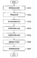
- FIG. 6 is a flowchart showing an operation example of the object detection device according to the embodiment disclosed in FIG. It is a figure which shows the relationship between the traveling direction of the object detection apparatus and the trunk region, and the limb region in the embodiment disclosed in FIG. It is a functional block diagram which shows the structure of the object detection apparatus of another example of 2nd Embodiment which concerns on this invention.
- the object detection device 1 of the present embodiment is mounted on a vehicle, for example, and tracks and detects an object such as a pedestrian existing around the vehicle.
- the trunk refers to the portion of the whole body of a person (pedestrian) excluding the limbs (left arm, right arm, left leg, right leg), that is, the head and the torso.
- the limbs shall indicate the limbs (left arm, right arm, left leg, right leg) which are the parts excluding the trunk.
- the trunk may be the body only, or the limbs may be one of the arms or legs.
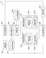
- FIG. 1 is a functional block diagram showing the configuration of the object detection device 1 of the first embodiment.
- the object detection device 1 of the present embodiment is composed of a camera, a computer, a memory, a storage device, and the like, and the computer operates as various functional units by executing a control program stored in the memory and the like.
- the object detection device 1 has an initial detection unit 100, a detection position storage unit 101, a vehicle information acquisition unit 102, a candidate area determination unit 103, and features as functional units realized by the operation of a camera or a computer. It has an extraction unit 104, a model information recording unit 105, a trunk likelihood calculation unit 106, a limb likelihood calculation unit 107, and a tracking area determination unit 108.
- the object detection device 1 detects a pedestrian in an image (camera image) sequentially acquired (captured) by the camera.
- the initial detection unit (position detection unit) 100 plays a role of initial detection of the pedestrian in the object detection device 1, and detects the initial position of the pedestrian in the camera image.
- a pedestrian may be detected by statistical machine learning, or a pedestrian may be detected by a heuristic method based on pixel gradient information. Any other known technique can be applied to detect pedestrians.
- the detection position storage unit 101 stores the detection position of a pedestrian detected by the initial detection unit 100 or the tracking area determination unit 108 described later.
- the pedestrian detection position information is stored when the pedestrian is detected in the frame.
- the stored information will be used in the next frame and will be treated as past data in the next frame.
- the vehicle information acquisition unit 102 acquires a control amount (also referred to as vehicle information) related to vehicle control such as the vehicle speed and yaw rate of the own vehicle.
- the controlled amount can be acquired via any medium through which the controlled amount of the vehicle is transmitted, such as the control area network of the vehicle.
- a pedestrian may appear in the frame this time based on the detection position of the pedestrian in the previous frame stored in the detection position storage unit 101 and the vehicle information acquired by the vehicle information acquisition unit 102 ( Determine a candidate area (which is a candidate for the tracking area).
- the candidate area is determined by applying the amount of movement of the vehicle between the previous frame and the current frame to the pedestrian detection position detected in the previous frame. Further, when the control amount of the vehicle cannot be acquired, the candidate area in the current frame may be determined with reference to the past detection position information of the pedestrian.
- the feature extraction unit 104 calculates an image feature amount (hereinafter, simply referred to as a feature amount) by analyzing pixel values for each candidate area determined by the candidate area determination unit 103. Specifically, the pixel value itself may be used, or a local region may be defined from a plurality of pixels and the average brightness in the local region may be used as the feature amount. In addition, the feature amount may be calculated from the gradient information of the image, and any feature amount handled in the image recognition field can be used.
- the model information recording unit 105 stores the feature amount calculated by the feature extraction unit 104 for the pedestrian area detected in the previous frame. In the storage of the model information recording unit 105, the feature amount in the tracking area determined by the tracking area determination unit 108, which will be described later, is stored and used in the tracking process in the next frame.
- the trunk likelihood calculation unit 106 calculates the similarity (similarity of the feature amount) of the trunk region set in advance for the previous frame and the current frame, and calculates the tracking score.
- the trunk likelihood calculation unit 106 holds the region information (also referred to as setting information) of the trunk in the candidate region in the trunk model 106A, and the similarity determination unit 106B built in the trunk likelihood calculation unit 106. Refers to the trunk region in the candidate area of the current frame and the tracking region of the previous frame, and acquires the feature quantity corresponding to the trunk region from the feature quantity calculated by the feature extraction unit 104.
- the trunk region is a preset image region of the pedestrian trunk in the candidate region of the current frame or the tracking region of the previous frame, corresponding to the region information of the trunk held in the trunk model 106A.
- the feature amount is calculated in each of the tracking area of the previous frame and the candidate area of the current frame, and the similarity determination unit 106B is the trunk of the previous frame (tracking area) and the current frame (candidate area). Similarity is judged by comparing the feature quantities of the regions. In the judgment of similarity, it is assumed that the difference between the feature amount (for example, the pixel value) of the trunk area of the previous frame (tracking area) and the current frame (candidate area) is less than or equal to the threshold value.
- the first tracking score indicating the similarity of the trunk region is calculated.
- the limb likelihood calculation unit 107 calculates the difference (difference in feature amount) from the preset limb region for the previous frame and the current frame, and calculates the tracking score.
- the limb likelihood calculation unit 107 holds the limb region information (also referred to as setting information) in the candidate region in the limb model 107A, and the difference determination unit 107B built in the limb likelihood calculation unit 107. Refers to the limb region in the candidate region of the current frame and the tracking region of the previous frame, and acquires the feature quantity corresponding to the limb region from the feature quantity calculated by the feature extraction unit 104.
- the limb region is a preset image region of the pedestrian's limb in the candidate region of the current frame or the tracking region of the previous frame, corresponding to the region information of the limb held in the limb model 107A. Is.
- the feature amount is calculated in each of the tracking area of the previous frame and the candidate area of the current frame, and the difference determination unit 107B is the limb part of the previous frame (tracking area) and the current frame (candidate area). Differences are judged by comparing the features of the regions.
- the difference is made when the difference between the feature amount (for example, the pixel value) of the limb region of the previous frame (tracking region) and the current frame (candidate region) is equal to or larger than the threshold value.
- the preset tracking scores for each feature amount By adding the preset tracking scores for each feature amount, a second tracking score indicating the difference between the limb regions is calculated.
- the tracking area determination unit 108 has a first tracking score calculated by the trunk likelihood calculation unit 106 and a second tracking score calculated by the limb likelihood calculation unit 107 from each candidate area determined by the candidate area determination unit 103. Based on the tracking score of, the tracking area of the pedestrian in this frame is determined. As a result, a pedestrian is detected from the camera image. The determined tracking area is stored in the detection position storage unit 101 for use in the next tracking.
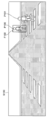
- FIG. 2 shows a scene (S100) in which the own vehicle enters the intersection and the pedestrian is traveling in the direction of approaching the vehicle on the pedestrian crossing.
- P100 indicates a pedestrian at time T
- P101 indicates an advanced pedestrian at time T + 1.
- the time corresponds to the frame acquired by the camera
- the time T corresponds to the previous frame
- the time T + 1 corresponds to the current frame.
- F100 in FIG. 2 shows the initial detection result corresponding to the pedestrian P100 at time T.
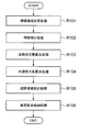
- the object detection device 1 includes a candidate area determination process (R101), a feature extraction process (R102), a trunk likelihood calculation process (R103), a limb likelihood calculation process (R104), a tracking area determination process (R105), and an estimation.
- the result storage process (R106) is performed in order to detect pedestrians in the image.
- each processing content will be described.
- the candidate area in the current frame is determined based on the detection result F100 of the previous frame.
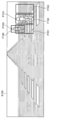
- FIG. 4 shows the determined candidate regions.
- F101, F102, and F103 are candidate regions corresponding to the pedestrian P101 in this frame.
- the candidate area is determined based on the vehicle behavior information (acquired by the vehicle information acquisition unit 102) that has moved from the previous frame to the current frame.
- the image feature amount is calculated from each candidate area determined in the candidate area determination process (R101).
- the detection result F100 of the previous frame and the candidate areas (F101, F102, and F103) in the current frame are resized to a predetermined size, and the feature amount is calculated from the resized image.
- the pixel value of each pixel is used as the feature amount.
- a pedestrian showing the similarity (similarity of features) of the trunk region between the detection result F100 of the previous frame and the candidate regions (F101, F102, and F103) in the current frame Calculate the tracking score of.
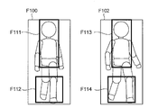
- F111 in the detection result F100 and F113 in the candidate region F102 indicate a preset trunk region.
- fi1 indicates the i-th pixel value acquired from the trunk region in the previous frame
- fi2 represents the i-th pixel value acquired from the trunk region in the current frame.
- threshold indicates the threshold value corresponding to the i-th pixel value. From equations (1) and (2), when the pixel values of the trunk region of the previous frame and the current frame are similar, that is, the difference between the pixel value fi1 and the pixel value fi2 is set in advance for each pixel. If it is less than or equal to the threshold threshold i, the preset tracking score Scorei is added for each pixel.
- the above calculation is performed for all pixels in the trunk region, and the tracking score of each pixel is added (for each pixel) to obtain the final tracking score (the first tracking score indicating the similarity of the trunk region). ).
- the explanation is made on the premise that the pixel value of the image is used as the feature amount, but similarly, when the feature amount defined in the local region is used instead of the pixel value, the same applies to (1) and (2). Calculate the tracking score according to the formula.
- a pedestrian showing the difference (difference in feature amount) in the limb region between the detection result F100 of the previous frame and the candidate regions (F101, F102, and F103) in the current frame Calculate the tracking score of.
- F112 in the detection result F100 and F114 in the candidate region F102 indicate preset limb regions.
- fi1 shows the i-th pixel value acquired from the limb region in the previous frame
- fi2 represents the i-th pixel value acquired from the limb region in the current frame.
- threshold indicates the threshold value corresponding to the i-th pixel value. From equations (3) and (4), when the pixel values of the limb region of the previous frame and the current frame are not similar, that is, the difference between the pixel value fi1 and the pixel value fi2 is set in advance for each pixel. If it is equal to or higher than the threshold threshold, the preset tracking score Scorei is added for each pixel.
- the above calculation is performed for all pixels in the limb region, and the tracking score of each pixel is added (for each pixel) to obtain the final tracking score (second tracking score indicating the difference in the limb region). ).
- the explanation is made on the premise that the pixel value of the image is used as the feature amount, but similarly, when the feature amount defined in the local region is used instead of the pixel value, the same applies to (3) and (4). Calculate the tracking score according to the formula.
- the trunk region is arranged at a position including the central side or the central portion, and the limb region is the peripheral side or the body. It is placed in a position that includes the periphery of the cadre area.
- the candidate area determination process (R101) is based on the tracking score S1 calculated by the trunk likelihood calculation process (R103) and the tracking score S2 calculated by the limb likelihood calculation process (R104). ),
- the tracking area in the frame this time is determined from the candidate areas (F101, F102, and F103).
- the tracking area is determined by calculating the tracking score for each candidate area (F101, F102, and F103).
- w1 and w2 can be variably set according to the distance to the pedestrian, the resolution of the image, the situation of the pedestrian, and the like.
- the candidate area with the maximum tracking score Score is set as the current tracking area.
- the tracking area information of the current frame determined by the tracking area determination process (R105) is stored in the memory (detection position storage unit 101) for pedestrian detection of the next frame.
- the object detection device 1 of the present embodiment is based on the initial detection unit (position detection unit) 100 that detects the position in the image of the pedestrian and the detection position in the image of the pedestrian in the previous frame.
- a candidate area determination unit 103 that determines a candidate area in a pedestrian image
- a feature extraction unit 104 that calculates a feature amount by analyzing pixel values for the candidate area
- a feature extraction unit 104 that are preset in the candidate area.
- the trunk region which is an image region of the trunk of a pedestrian, is referred to, and a first tracking score indicating the similarity of the feature amount of the trunk region of the current frame and the previous frame is calculated.
- a limb likelihood calculation unit 107 that calculates a second tracking score indicating sex, and a tracking area determination unit 108 that determines a tracking area in the current frame based on the first tracking score and the second tracking score. , Equipped with.
- the object detection device 1 of the present embodiment acquires the feature amount from the preset trunk region and limb region, the trunk region has the similarity of the feature quantity, and the limb region has the difference in the feature quantity. Detects pedestrians based on. As a result, pop-out pedestrians such as intersections are imaged in the wide-angle part of the image, so even if the resolution is insufficient due to the influence of lens distortion and the like, and pedestrian parts cannot be detected stably, in advance.
- the trunk region and the limb region and changing the score calculation method (changed according to similarity and difference) according to the set region, pedestrians can be tracked stably.
- the pedestrian can be tracked stably. Therefore, the detection accuracy of pedestrians can be improved.
- the tracking area determination process (R105) by the tracking area determination unit 108 it was explained that the candidate area having the maximum tracking score is used as the tracking result in this frame, but the tracking score of the candidate area having the maximum tracking score is used. If is equal to or less than a predetermined threshold value, there may be no target to be detected in the frame this time. This can reduce erroneous tracking when a pedestrian is shielded by a wall or other object.
- the object detection device 2 of the present embodiment tracks and detects an object such as a pedestrian existing around the vehicle in consideration of the state of the object (progress state including the traveling direction, the stationary state, and the moving state). ..
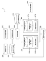
- FIG. 6 is a functional block diagram showing the configuration of the object detection device 2 of the second embodiment.
- the object detection device 2 has an initial detection unit 200, a detection position storage unit 201, a vehicle information acquisition unit 202, a candidate area determination unit 203, and features as functional units realized by the operation of a camera or a computer. It has an extraction unit 204, a model information recording unit 205, a trunk likelihood calculation unit 206, a limb likelihood calculation unit 207, a tracking area determination unit 208, and a state estimation unit 209.
- the functions of the initial detection unit 200, the detection position storage unit 201, the vehicle information acquisition unit 202, the candidate area determination unit 203, the feature extraction unit 204, and the model information recording unit 205 are basically the same as those of the first embodiment described above. ..
- the initial detection unit (position detection unit) 200 plays a role of initial detection of the pedestrian in the object detection device 2, and detects the initial position of the pedestrian in the camera image.
- the detection position storage unit 202 stores the detection position of the pedestrian detected by the initial detection unit 200 or the tracking area determination unit 208 described later.
- the vehicle information acquisition unit 202 acquires a control amount (vehicle information) related to vehicle behavior control such as vehicle speed and yaw rate of the vehicle on which the object detection device 2 is mounted.
- the candidate area determination unit 203 refers to the pedestrian detection position information in the previous frame stored in the detection position storage unit 201 and the vehicle information acquired by the vehicle information acquisition unit 202, and a pedestrian appears in this frame. Determine the candidate area to obtain (candidate for tracking area).
- the feature extraction unit 204 calculates the image feature amount by analyzing the pixel values for each candidate area determined by the candidate area determination unit 203.
- the model information recording unit 205 stores the feature amount calculated by the feature extraction unit 204 in the previous frame.
- the state estimation unit 209 estimates the progress status and the direction of travel as the state of the pedestrian.
- the progress status includes information indicating whether the pedestrian to be detected is moving (moving) or stopped.
- the traveling direction includes information indicating whether the pedestrian to be detected is moving in the horizontal direction or the vertical direction.
- the history of tracking results up to this frame is used. It is estimated whether a pedestrian is moving based on the tracking history and the behavior information of the vehicle up to the frame this time.
- the pedestrian's traveling direction may be estimated based on the tracking history and the vehicle behavior information up to the frame this time, or the pedestrian's traveling direction may be estimated by a statistical machine learning method.
- the posture of the person with respect to the own vehicle may be estimated and used as the direction of travel. Any known technique other than the method shown here can be applied to the estimation of the progress status and the direction of travel of the pedestrian.
- the estimation result in the state estimation unit 209 is sent to the trunk likelihood calculation unit 206 and the limb likelihood calculation unit 207, and the trunk and limb parts in the candidate region held by the trunk model 206A and the limb model 207A. It is used for setting (selecting) the area information (setting information) of the above, and is sent to the tracking area determination unit 208, and is used for setting (selecting) weights for the first tracking score and the second tracking score.
- the trunk likelihood calculation unit 206 determines the similarity (similarity of the feature amount) from the preset trunk region in the previous frame and the current frame, and calculates the tracking score.
- the trunk region set in advance can be changed. Specifically, the trunk likelihood calculation unit 206 holds the region information of a plurality of (different) trunks in the candidate region in the trunk model 206A, and the similarity determination built in the trunk likelihood calculation unit 206.
- the unit 206B responds to the traveling direction of the pedestrian from the trunk model 206A (region information of a plurality of trunks held in the trunk model 206A).
- the trunk area having the area information according to the traveling direction of the pedestrian is set, in other words, the trunk area is set according to the traveling direction of the pedestrian.
- the area information it is possible to change the trunk area preset in the candidate area, determine the similarity from the trunk area, and calculate the tracking score.
- the limb likelihood calculation unit 207 determines the difference (difference in feature amount) from the preset limb region in the previous frame and the current frame, and calculates the tracking score.
- the preset limb region can be changed.
- the limb likelihood calculation unit 207 holds region information of a plurality of (different) limbs in the candidate region in the limb model 207A, and determines the difference built in the limb likelihood calculation unit 207.
- the unit 207B responds to the traveling direction of the pedestrian from the limb model 207A (region information of a plurality of limbs held in the limb model 207A).
- the limb model 207A region information of a plurality of limbs held in the limb model 207A.
- the area information of the limbs By setting (selecting) the area information of the limbs, the limb area having the area information according to the traveling direction of the pedestrian is set, in other words, the limbs are set according to the traveling direction of the pedestrian.
- the area information it is possible to change the limb area preset in the candidate area, judge the difference from the limb area, and calculate the tracking score.
- the tracking area determination unit 208 has a first tracking score calculated by the trunk likelihood calculation unit 206 and a second tracking score calculated by the limb likelihood calculation unit 207 from each candidate area determined by the candidate area determination unit 203. Based on the tracking score of, the tracking area of the pedestrian in this frame is determined. As a result, a pedestrian is detected from the camera image. Further, the tracking area determination unit 208 changes the weights of the first tracking score and the second tracking score according to the progress of the pedestrian estimated by the state estimation unit 209, in other words, the state estimation unit 209. Weights according to the progress of the pedestrian estimated in 1 can be set for the first tracking score and the second tracking score, and the final tracking area of the pedestrian can be determined.
- the object detection device 2 includes a candidate area determination process (R201), a feature extraction process (R202), a pedestrian state estimation process (R203), a trunk likelihood calculation process (R204), and a limb likelihood calculation process (R205).
- the tracking area determination process (R206) and the estimation result storage process (R207) are performed in order to detect a pedestrian in the image.
- the differences from the processing performed by the flowchart of FIG. 3 are the pedestrian state estimation processing (R203), the trunk likelihood calculation processing (R204), the limb likelihood calculation processing (R205), and the tracking area determination of FIG. Processing (R206). Therefore, in the following, the pedestrian state estimation process (R203), the trunk likelihood calculation process (R204), the limb likelihood calculation process (R205), and the tracking area determination process (R206), which are the differences, will be described in detail. ..
- the progress status and the direction of travel of the pedestrian are estimated as the state of the pedestrian in the current frame.
- the estimation of the progress status it is determined whether the pedestrian is moving or stopped from the past tracking position of the pedestrian and the vehicle behavior information up to the frame this time.
- the traveling direction whether the pedestrian is traveling laterally with respect to the own vehicle as the traveling direction of the pedestrian from the past tracking position of the pedestrian and the vehicle behavior information up to the frame this time. , Judge whether it is progressing in the vertical direction.
- the trunk area is changed according to the traveling direction of the pedestrian estimated by the pedestrian state estimation process (R203), and the features of the past frame and the current frame in the changed trunk area.
- the amounts eg, pixel values
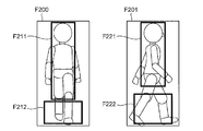
- FIG. 8 shows the relationship between the traveling direction and the trunk region.
- F200 in FIG. 8 shows a case where the traveling direction is determined to be the vertical direction
- F201 indicates a case where the traveling direction is determined to be the horizontal direction.
- F211 in F200 and F221 in F201 indicate the trunk region.
- the trunk region is expanded as compared with the case where the pedestrian is traveling in the horizontal direction (in FIG. 8, it is expanded downward. It is spread out).
- the limb area is changed according to the traveling direction of the pedestrian estimated by the pedestrian state estimation process (R203), and the features of the past frame and the current frame in the changed limb area.
- the amount eg, pixel value
- F212 in F200 and F222 in F201 indicate the limb region. Since the pedestrian is traveling in the horizontal direction in F201, it is considered that the area where the appearance changes is larger than that in the case where the pedestrian is traveling in the vertical direction. Therefore, when the pedestrian is traveling in the lateral direction, the limb region is expanded as compared with the case where the pedestrian is traveling in the vertical direction (in FIG. 8, it is expanded upward. It is spread out).
- the trunk region is arranged at a position including the central side or the central portion, and the limb region is It is placed at a position including the peripheral side or the periphery of the trunk area.
- the tracking area determination process (R206), it is calculated by the trunk likelihood calculation process (R204) and the limb likelihood calculation process (R205) according to the progress of the pedestrian estimated by the pedestrian state estimation process (R203).
- w1 is a weight for the tracking score S1
- w2 is a weight for the tracking score S2.
- the weight on the trunk region the region where the change in appearance is considered to be small
- the limb region weaken the weight for (the area where the change in appearance is considered to be large).
- w1 and w2 can be variably set according to the distance to the pedestrian, the resolution of the image, the situation of the pedestrian, and the like. According to the above formula, the candidate area with the highest tracking score Score is set as the current tracking area.
- the object detection device 2 of the present embodiment further includes a state estimation unit 209 for estimating the traveling direction and progress of the pedestrian, and the trunk portion likelihood calculation unit 206 and the limb portion likelihood calculation unit 207.
- the traveling direction is estimated by the state estimation unit 209
- the setting information of the trunk region and the limb region in the candidate region is changed according to the traveling direction
- the tracking region determining unit 208 changes the setting information.
- the tracking area is determined by changing the weights for the first tracking score and the second tracking score according to the progress.
- the state estimation unit 209 for estimating the traveling direction and progress of the pedestrian is further provided, and the trunk likelihood calculation unit 206 and the limb likelihood calculation unit 207 are estimated by the state estimation unit 209.
- the trunk region and the limb region having the setting information according to the traveling direction are set, and the tracking region determining unit 208 sets the weight according to the progress estimated by the state estimation unit 209 to the first.
- the tracking area is determined by setting the tracking score of the above and the second tracking score.
- the object detection device 2 of the present embodiment can change the position and size of the trunk region and the limb region according to the traveling direction of the pedestrian. As a result, the pedestrian can be detected stably even when the similar part and the dissimilar part change in time series due to the change in the traveling direction of the pedestrian. Further, the object detection device 2 of the present embodiment determines whether the pedestrian is moving or stationary, and when the pedestrian is stationary, the influence of the tracking score calculated by the trunk likelihood calculation unit 206 is exerted. Strengthen and weaken the influence of the tracking score calculated by the limb likelihood calculation unit 207. As a result, the pedestrian can be detected stably even when it is determined that the movement of the pedestrian is small. Therefore, the detection accuracy of pedestrians can be improved.
- the positions and sizes of the trunk region and the limb region are changed according to the traveling direction of the pedestrian. And at least one position or size of the limb region can be changed. Specifically, even when the size of the pedestrian detected by the initial detection unit 200 is small, that is, when it can be determined that the pedestrian is a child, the positions and sizes of the trunk region and the limb region can be changed in the same manner. can. In this way, by discriminating the type of tracking target and adjusting the position and size of the trunk region and limb region, it is possible to stably track subjects with different physiques such as adults and children. ..
- the initial detection unit 200 has determined that the child is a child, but as shown in FIG. 9, for example, the external environment recognition unit 210 capable of recognizing the external environment such as a structure in the traveling path has an external environment.
- the structure indicating the school zone is recognized according to the recognition result of the recognition unit 210, the position and size (that is, corresponding to the setting information) of at least one of the trunk region and the limb region are changed. You can also do it.
- the external environment recognition unit 210 capable of recognizing the school zone a monocular camera, a compound eye system having a plurality of cameras, a stereo camera using parallax, a sensing system exemplified by LIDAR, and a combination thereof can be used.
- the external environment recognition unit 210 recognizes the school zone, at least one position of the trunk region and the limb region shifts downward as compared with before the recognition.
- the size of at least one of the trunk region and the limb region is made smaller than before the recognition. Since the physique of a child is smaller than that of an adult, by changing the position and size of at least one of the trunk region and the limb region as described above, it is stable for subjects with different physiques such as adults and children. Can be tracked.
- the time information obtained by the clock in the car or wireless communication can also be used to recognize the school zone. By doing so, it is possible to accurately capture the child during times of heavy traffic such as when going to school or leaving school.
- the present invention has been described above with reference to the first embodiment and the second embodiment, the present invention is not limited to the above embodiment.
- Various changes that can be understood by the parties within the scope of the present invention can be made to the structure and details of the present invention.
- the above-described embodiment has been described in detail in order to explain the present invention in an easy-to-understand manner, and is not necessarily limited to the one including all the described configurations.
- each of the above configurations, functions, processing units, processing means, etc. may be realized by hardware by designing a part or all of them by, for example, an integrated circuit. Further, each of the above configurations, functions, and the like may be realized by software by the processor interpreting and executing a program that realizes each function. Information such as programs, tables, and files that realize each function can be stored in a memory, a hard disk, a storage device such as an SSD (Solid State Drive), or a recording medium such as an IC card, an SD card, or a DVD.
- SSD Solid State Drive
- control lines and information lines indicate what is considered necessary for explanation, and not all control lines and information lines are necessarily shown on the product. In practice, it can be considered that almost all configurations are interconnected.
- Object detection device (first embodiment) 2 Object detection device (second embodiment) 100, 200 Initial detection unit (position detection unit) 101, 201 Detection position storage unit 102, 202 Vehicle information acquisition unit 103, 203 Candidate area determination unit 104, 204 Feature extraction unit 105, 205 Model information recording unit 106, 206 Trunk likelihood calculation unit 107, 207 Limb likelihood Calculation unit 108, 208 Tracking area determination unit 209 State estimation unit 210 External environment recognition unit
Landscapes
- Engineering & Computer Science (AREA)
- Physics & Mathematics (AREA)
- General Physics & Mathematics (AREA)
- Theoretical Computer Science (AREA)
- Multimedia (AREA)
- Computer Vision & Pattern Recognition (AREA)
- Artificial Intelligence (AREA)
- Health & Medical Sciences (AREA)
- Human Computer Interaction (AREA)
- Computing Systems (AREA)
- Databases & Information Systems (AREA)
- Evolutionary Computation (AREA)
- General Health & Medical Sciences (AREA)
- Medical Informatics (AREA)
- Software Systems (AREA)
- Chemical & Material Sciences (AREA)
- Analytical Chemistry (AREA)
- Traffic Control Systems (AREA)
- Image Analysis (AREA)
Abstract
本発明は、歩行者の検出を高精度化することができる物体検出装置を提供することを目的とする。前回フレームの歩行者の画像中における検出位置に基づき今回フレームの歩行者の画像中における候補領域を決定する候補領域決定部103と、前記候補領域に対して画素値を解析することで特徴量を算出する特徴抽出部104と、前記候補領域において事前に設定された体幹部領域を参照し、前記今回フレームと前記前回フレームの前記体幹部領域の前記特徴量の類似性を示す第1の追跡スコアを算出する体幹部尤度算出部106と、前記候補領域において事前に設定された四肢部領域を参照し、前記今回フレームと前記前回フレームの前記四肢部領域の前記特徴量の相違性を示す第2の追跡スコアを算出する四肢部尤度算出部107と、前記第1の追跡スコア及び前記第2の追跡スコアに基づき前記今回フレームにおける追跡領域を決定する追跡領域決定部108と、を備える。
Description
本発明は、物体検出装置に関する。
自動運転の実現や交通事故防止のために、歩行者を検出してブレーキ制御をおこなう自動ブレーキ機能に大きな関心が寄せられている。歩行者の検出方法として、特許文献1では、検出対象の胴体部を検出し、その後、検出した胴体部の周囲にある四肢部の検出を行う。検出した胴体部、及び四肢部のスコアに基づき歩行者を検出する。
特許文献1では、四肢部の検出を行う必要がある。しかしながら、胴体部に比べて四肢部は小さく撮像されるため、四肢部の安定的な検出は困難であり、特に遠方に歩行者が存在している場合や解像度の低い画像において、歩行者の検出が課題となる。
本発明は、このような課題に鑑み、歩行者の検出を高精度化することができる物体検出装置を提供することを目的とする。
上記課題を解決するため、本発明に係る物体検出装置は、歩行者の画像中における位置を検出する位置検出部と、前回フレームの歩行者の画像中における検出位置に基づき今回フレームの歩行者の画像中における候補領域を決定する候補領域決定部と、前記候補領域に対して画素値を解析することで特徴量を算出する特徴抽出部と、前記候補領域において事前に設定された歩行者の体幹部の画像領域である体幹部領域を参照し、前記今回フレームと前記前回フレームの前記体幹部領域の前記特徴量の類似性を示す第1の追跡スコアを算出する体幹部尤度算出部と、前記候補領域において事前に設定された歩行者の四肢部の画像領域である四肢部領域を参照し、前記今回フレームと前記前回フレームの前記四肢部領域の前記特徴量の相違性を示す第2の追跡スコアを算出する四肢部尤度算出部と、前記第1の追跡スコア及び前記第2の追跡スコアに基づき前記今回フレームにおける追跡領域を決定する追跡領域決定部と、を備えることを特徴とする。
本発明によれば、歩行者の検出精度を向上することができる。
上記した以外の課題、構成及び効果は以下の実施形態の説明により明らかにされる。
以下に、本発明の実施形態について詳細に説明する。なお、以下の実施形態の説明において、同一の機能を有する部分には同一の又は関連する符号を付し、その繰り返し説明は省略する場合がある。
[第1実施形態]
本実施形態の物体検出装置1は、例えば車両に搭載され、車両周辺に存在する歩行者などの物体を追跡して検出する。なお、以下の実施形態の説明において、体幹部とは、人(歩行者)の全身のうち四肢(左腕、右腕、左脚、右脚)を除いた部分、つまり、頭部及び胴体部を示し、四肢部とは、体幹部を除いた部分である四肢(左腕、右腕、左脚、右脚)を示すものとする。なお、体幹部を胴体部のみとしてもよいし、四肢部を腕部又は脚部の一方としてもよい。
本実施形態の物体検出装置1は、例えば車両に搭載され、車両周辺に存在する歩行者などの物体を追跡して検出する。なお、以下の実施形態の説明において、体幹部とは、人(歩行者)の全身のうち四肢(左腕、右腕、左脚、右脚)を除いた部分、つまり、頭部及び胴体部を示し、四肢部とは、体幹部を除いた部分である四肢(左腕、右腕、左脚、右脚)を示すものとする。なお、体幹部を胴体部のみとしてもよいし、四肢部を腕部又は脚部の一方としてもよい。
(機能ブロック構成例)
図1は、第1実施形態の物体検出装置1の構成を示す機能ブロック図である。
図1は、第1実施形態の物体検出装置1の構成を示す機能ブロック図である。
本実施形態の物体検出装置1は、カメラ、コンピュータ、メモリ及び記憶装置などで構成されており、コンピュータが、メモリなどに格納された制御プログラムを実行することにより各種機能部として動作する。
図1に示すように、物体検出装置1は、カメラやコンピュータの動作により実現される機能部として、初期検出部100、検出位置記憶部101、車両情報取得部102、候補領域決定部103、特徴抽出部104、モデル情報記録部105、体幹部尤度算出部106、四肢部尤度算出部107、追跡領域決定部108を有している。物体検出装置1は、カメラにより逐次取得(撮像)される画像(カメラ画像)において歩行者を検出する。
初期検出部(位置検出部)100は、物体検出装置1における歩行者の初期検出の役割を担い、カメラ画像における歩行者の初期位置を検出する。検出手段としては、統計的な機械学習により歩行者を検出してもよいし、画素の勾配情報に基づくヒューリスティックな手法により歩行者を検出してもよい。他にもいかなる公知技術を適用し、歩行者を検出することができる。
検出位置記憶部101は、初期検出部100、若しくは後述する追跡領域決定部108で検出した歩行者の検出位置が格納される。歩行者の検出位置情報の格納は、当該フレームで歩行者が検出された際に行われる。また、格納された情報は、次回フレームで利用され、次回のフレームでは過去データとして扱われる。
車両情報取得部102では、自車両の車速、ヨーレートなどの車両制御に関する制御量(車両情報ともいう)を取得する。制御量は、車両のコントロールエリアネットワークなどの車両の制御量が伝達される如何なる媒体を経由して取得できる。
候補領域決定部103では、検出位置記憶部101に格納された前回フレームにおける歩行者の検出位置、及び車両情報取得部102で取得される車両情報に基づき、今回フレームにおいて歩行者が出現し得る(追跡領域の候補となる)候補領域を決定する。候補領域は、前回フレームで検出された歩行者の検出位置に対して前回フレームと今回フレーム間での車両の移動量を適用することで決定される。また、車両の制御量が取得できない場合においては、過去の歩行者の検出位置情報を参考に、今回フレームにおける候補領域を決定してもよい。
特徴抽出部104は、候補領域決定部103で決定した各候補領域に対して、画素値を解析することで画像特徴量(以下、単に特徴量という)を算出する。具体的には、画素値そのものを利用してもよいし、複数のピクセルから局所領域を定義し、局所領域内の平均輝度を特徴量としてもよい。その他にも、画像の勾配情報から特徴量を算出してもよく、画像認識分野で扱われる任意の特徴量を利用することができる。
モデル情報記録部105は、前回フレームで検出された歩行者領域に対して特徴抽出部104が算出した特徴量が保存される。モデル情報記録部105の保存は、後述する追跡領域決定部108が決定した追跡領域内の特徴量が保存され、次回のフレームにおける追跡処理で利用される。
体幹部尤度算出部106は、事前に設定された体幹部領域の類似性(特徴量の類似性)を前回フレームと今回フレームに対して計算し、追跡スコアを算出する。体幹部尤度算出部106は、候補領域における体幹部の領域情報(設定情報ともいう)を体幹部モデル106Aに保持しており、体幹部尤度算出部106に内蔵された類似性判断部106Bは、今回フレームの候補領及び前回フレームの追跡領域において体幹部領域を参照し、特徴抽出部104が算出した特徴量から体幹部領域に対応した特徴量を取得する。体幹部領域とは、今回フレームの候補領域又は前回フレームの追跡領域において、体幹部モデル106Aに保持された体幹部の領域情報に対応して、事前に設定された歩行者の体幹部の画像領域である。特徴量の算出は、前回フレームの追跡領域、及び今回フレームの候補領域それぞれで実施しており、類似性判断部106Bは、前回フレーム(の追跡領域)と今回フレーム(の候補領域)の体幹部領域の特徴量を比較することで類似性を判断する。類似性の判断では、前回フレーム(の追跡領域)と今回フレーム(の候補領域)の体幹部領域の特徴量(例えば、画素値)の差が閾値以下である場合に類似しているものとして、特徴量毎に事前に設定された追跡スコアを加算することで、体幹部領域の類似性を示す第1の追跡スコアを算出する。
四肢部尤度算出部107は、事前に設定された四肢部領域から相違性(特徴量の相違性)を前回フレームと今回フレームに対して計算し、追跡スコアを算出する。四肢部尤度算出部107は、候補領域における四肢部の領域情報(設定情報ともいう)を四肢部モデル107Aに保持しており、四肢部尤度算出部107に内蔵された相違性判断部107Bは、今回フレームの候補領及び前回フレームの追跡領域において四肢部領域を参照し、特徴抽出部104が算出した特徴量から四肢部領域に対応した特徴量を取得する。四肢部領域とは、今回フレームの候補領域又は前回フレームの追跡領域において、四肢部モデル107Aに保持された四肢部の領域情報に対応して、事前に設定された歩行者の四肢部の画像領域である。特徴量の算出は、前回フレームの追跡領域、及び今回フレームの候補領域それぞれで実施しており、相違性判断部107Bは、前回フレーム(の追跡領域)と今回フレーム(の候補領域)の四肢部領域の特徴量を比較することで相違性を判断する。相違性の判断では、前回フレーム(の追跡領域)と今回フレーム(の候補領域)の四肢部領域の特徴量(例えば、画素値)の差が閾値以上である場合に相違しているものとして、特徴量毎に事前に設定された追跡スコアを加算することで、四肢部領域の相違性を示す第2の追跡スコアを算出する。
追跡領域決定部108は、候補領域決定部103で決定した各候補領域の中から、体幹部尤度算出部106が算出した第1の追跡スコアと四肢部尤度算出部107が算出した第2の追跡スコアに基づき、今回フレームにおける歩行者の追跡領域を決定する。これにより、カメラ画像から歩行者を検出する。決定された追跡領域は、次回の追跡に利用するため、検出位置記憶部101に格納される。
(動作例)
次に、図2に示すシーンにおける本実施形態の物体検出装置1の動作例を、図3のフローチャートを参照して説明する。以降の動作例では、物体検出装置1は車両の前方を監視する形式で設置されているものとする。また、以降で物体検出装置1の動作例を説明するが、すでに初期検出部100による歩行者の初期検出は実施されており、その検出結果は検出位置記憶部101に格納されているものとする。
次に、図2に示すシーンにおける本実施形態の物体検出装置1の動作例を、図3のフローチャートを参照して説明する。以降の動作例では、物体検出装置1は車両の前方を監視する形式で設置されているものとする。また、以降で物体検出装置1の動作例を説明するが、すでに初期検出部100による歩行者の初期検出は実施されており、その検出結果は検出位置記憶部101に格納されているものとする。
図2は、自車両は交差点に進入し、歩行者は横断歩道を車両に接近する方向に進行しているシーン(S100)を示している。ここで、P100は時刻Tにおける歩行者を示しており、P101は時刻T+1における進行した歩行者を示している。ここで、時刻は、カメラの取得するフレームに対応しており、時刻Tは前回フレーム、時刻T+1は今回フレームに対応している。図2中のF100は、時刻Tの歩行者P100に対応した初期検出結果を示している。
物体検出装置1は、候補領域決定処理(R101)、特徴抽出処理(R102)、体幹部尤度算出処理(R103)、四肢部尤度算出処理(R104)、追跡領域決定処理(R105)、推定結果格納処理(R106)を順に実施し、画像中における歩行者の検出を行う。以降では、各処理内容に関して説明する。
候補領域決定処理(R101)では、前回フレームの検出結果F100に基づき今回フレームにおける候補領域を決定する。図4に決定された候補領域を示す。F101、F102、及びF103は今回フレームにおける歩行者P101に対応した候補領域である。候補領域は、前回フレームから今回フレームまでに移動した車両挙動情報(車両情報取得部102で取得)に基づき決定される。
特徴抽出処理(R102)では、候補領域決定処理(R101)で決定した各候補領域から画像特徴量を算出する。前回フレームの検出結果F100、及び今回フレームにおける候補領域(F101、F102、及びF103)は所定のサイズにリサイズされ、リサイズされた画像中から特徴量を算出する。以降では、特徴量として各ピクセルの画素値を用いたものとして説明する。
体幹部尤度算出処理(R103)では、前回フレームの検出結果F100と今回フレームにおける候補領域(F101、F102、及びF103)との体幹部領域の類似性(特徴量の類似性)を示す歩行者の追跡スコアを算出する。以降では、前回フレームの検出結果F100と今回フレームの候補領域F102における類似度計算、及び追跡スコアの算出方法に関して図5を用いて説明する。図5において、検出結果F100におけるF111、及び候補領域F102におけるF113は事前に設定された体幹部領域を示している。体幹部モデル106Aに保持された体幹部の領域情報(設定情報)を用いることにより、F111、及びF113はリサイズされた画像において同一位置に配置されている。つまり、領域F111、及びF113内に含まれる特徴量数、すなわち画素数は一致する。類似度計算では、F111、及びF113に含まれる全画素の値(画素値)を比較する。類似度に基づく追跡スコアは、次の式(1)、(2)に従い計算される。
[数1] Scorei = wi, if fi1 - fi2 <= thresholdi ・・・(1)
[数2] Scorei = 0, if fi1 - fi2 > thresholdi ・・・(2)
[数1] Scorei = wi, if fi1 - fi2 <= thresholdi ・・・(1)
[数2] Scorei = 0, if fi1 - fi2 > thresholdi ・・・(2)
式(1)、(2)においてScorei(=wi)は、i番目の画素から算出される追跡スコアである。fi1は前回フレームにおける体幹部領域から取得されたi番目の画素値を示しており、fi2は今回フレームにおける体幹部領域から取得されたi番目の画素値を表している。また、thresholdiは、i番目の画素値に対応した閾値を示している。式(1)、(2)から、前回フレームと今回フレームの体幹部領域の画素値が類似している場合には、すなわち、画素値fi1と画素値fi2の差が画素ごとに事前に設定された閾値thresholdi以下である場合には、画素ごとに事前に設定された追跡スコアScoreiを加算する。以上の計算を体幹部領域の全画素に対して実施し、各画素の追跡スコアを(画素ごとに)加算したものを最終的な追跡スコア(体幹部領域の類似性を示す第1の追跡スコア)とする。以上では、特徴量として画像の画素値を利用することを前提に説明したが、画素値ではなく局所領域において定義される特徴量を利用する場合にも同様に(1)、及び(2)の数式に従い追跡スコアを算出する。
四肢部尤度算出処理(R104)では、前回フレームの検出結果F100と今回フレームにおける候補領域(F101、F102、及びF103)との四肢部領域の相違性(特徴量の相違性)を示す歩行者の追跡スコアを算出する。以降では、前回フレームの検出結果F100と今回フレームの候補領域F102における相違度計算、及び追跡スコアの算出方法に関して図5を用いて説明する。図5において、検出結果F100におけるF112、及び候補領域F102におけるF114は事前に設定された四肢部領域を示している。四肢部モデル107Aに保持された四肢部の領域情報(設定情報)を用いることにより、F112、及びF114はリサイズされた画像において同一位置に配置されている。つまり、領域F112、及びF114内に含まれる特徴量数、すなわち画素数は一致する。相違度計算では、F112、及びF114に含まれる全画素の値(画素値)を比較する。相違度に基づく追跡スコアは、次の式(3)、(4)に従い計算される。
[数3] Scorei = wi, if fi1 - fi2 >= thresholdi ・・・(3)
[数4] Scorei = 0, if fi1 - fi2 < thresholdi ・・・(4)
[数3] Scorei = wi, if fi1 - fi2 >= thresholdi ・・・(3)
[数4] Scorei = 0, if fi1 - fi2 < thresholdi ・・・(4)
式(3)、(4)においてScorei(=wi)は、i番目の画素から算出される追跡スコアである。fi1は前回フレームにおける四肢部領域から取得されたi番目の画素値を示しており、fi2は今回フレームにおける四肢部領域から取得されたi番目の画素値を表している。また、thresholdiは、i番目の画素値に対応した閾値を示している。式(3)、(4)から、前回フレームと今回フレームの四肢部領域の画素値が類似していない場合には、すなわち、画素値fi1と画素値fi2の差が画素ごとに事前に設定された閾値thresholdi以上である場合には、画素ごとに事前に設定された追跡スコアScoreiを加算する。以上の計算を四肢部領域の全画素に対して実施し、各画素の追跡スコアを(画素ごとに)加算したものを最終的な追跡スコア(四肢部領域の相違性を示す第2の追跡スコア)とする。以上では、特徴量として画像の画素値を利用することを前提に説明したが、画素値ではなく局所領域において定義される特徴量を利用する場合にも同様に(3)、及び(4)の数式に従い追跡スコアを算出する。
なお、図5に示すように、基本的に、今回フレームの候補領域又は前回フレームの追跡領域において、体幹部領域は中央側ないし中央部を含む位置に配置され、四肢部領域は周辺側ないし体幹部領域の周囲を含む位置に配置される。
追跡領域決定処理(R105)では、体幹部尤度算出処理(R103)が算出した追跡スコアS1、及び四肢部尤度算出処理(R104)が算出した追跡スコアS2に基づき、候補領域決定処理(R101)で決定した各候補領域(F101、F102、及びF103)の中から、今回フレームにおける追跡領域を決定する。追跡領域は、各候補領域(F101、F102、及びF103)に対して追跡スコアを算出することで決定される。ここでの追跡スコアは、例えばScore=w1*S1+w2*S2に従い算出される。ここで、w1、w2は追跡スコアの重みづけ係数であり、例えばw1=0.5、w2=0.5のような値を用いる。w1、w2は、例えば、歩行者との距離や画像の解像度、歩行者の状況などに応じて可変に設定することもできる。上述した計算式に従い、追跡スコアScoreが最大の候補領域を今回の追跡領域とする。
推定結果格納処理(R106)では、追跡領域決定処理(R105)で決定した今回フレームの追跡領域情報を次回フレームの歩行者検出のためにメモリ(検出位置記憶部101)に格納する。
(作用効果)
以上より、本実施形態の物体検出装置1は、歩行者の画像中における位置を検出する初期検出部(位置検出部)100と、前回フレームの歩行者の画像中における検出位置に基づき今回フレームの歩行者の画像中における候補領域を決定する候補領域決定部103と、前記候補領域に対して画素値を解析することで特徴量を算出する特徴抽出部104と、前記候補領域において事前に設定された歩行者の体幹部の画像領域である体幹部領域を参照し、前記今回フレームと前記前回フレームの前記体幹部領域の前記特徴量の類似性を示す第1の追跡スコアを算出する体幹部尤度算出部106と、前記候補領域において事前に設定された歩行者の四肢部の画像領域である四肢部領域を参照し、前記今回フレームと前記前回フレームの前記四肢部領域の前記特徴量の相違性を示す第2の追跡スコアを算出する四肢部尤度算出部107と、前記第1の追跡スコア及び前記第2の追跡スコアに基づき前記今回フレームにおける追跡領域を決定する追跡領域決定部108と、を備える。
以上より、本実施形態の物体検出装置1は、歩行者の画像中における位置を検出する初期検出部(位置検出部)100と、前回フレームの歩行者の画像中における検出位置に基づき今回フレームの歩行者の画像中における候補領域を決定する候補領域決定部103と、前記候補領域に対して画素値を解析することで特徴量を算出する特徴抽出部104と、前記候補領域において事前に設定された歩行者の体幹部の画像領域である体幹部領域を参照し、前記今回フレームと前記前回フレームの前記体幹部領域の前記特徴量の類似性を示す第1の追跡スコアを算出する体幹部尤度算出部106と、前記候補領域において事前に設定された歩行者の四肢部の画像領域である四肢部領域を参照し、前記今回フレームと前記前回フレームの前記四肢部領域の前記特徴量の相違性を示す第2の追跡スコアを算出する四肢部尤度算出部107と、前記第1の追跡スコア及び前記第2の追跡スコアに基づき前記今回フレームにおける追跡領域を決定する追跡領域決定部108と、を備える。
すなわち、本実施形態の物体検出装置1は、事前に設定された体幹部領域及び四肢部領域から特徴量を取得し、体幹部領域は特徴量の類似性、四肢部領域は特徴量の相違性に基づき歩行者を検出する。これにより、交差点などの飛び出し歩行者などは画像中の広角部に撮像されるため、レンズ歪みなどの影響により解像度が不足し、歩行者の部位などを安定的に検出できない場合においても、事前に体幹部部領域と四肢部領域を設定し、設定した領域に応じてスコア算出方法を変更(類似性と相違性で変更)することで、安定的に歩行者を追跡することができる。また、遠方の歩行者において歩行者が小さく撮像され、安定的に歩行者の部位を検出することが難しい場合においても、安定的に歩行者を追跡することができる。したがって、歩行者の検出精度を向上することができる。
また、追跡領域決定部108による追跡領域決定処理(R105)では、追跡スコアが最大となる候補領域を今回フレームにおける追跡結果とすることを説明したが、追跡スコアが最大となる候補領域の追跡スコアが所定の閾値以下である場合、今回フレームにおいて検出すべき対象がいないとしてもよい。これにより、歩行者が壁や他の物体に遮蔽された場合において、誤って追跡することを低減できる。
[第2実施形態]
本実施形態の物体検出装置2は、物体の状況(進行方向や、静止状態、移動状態を含む進行状況)を考慮して、車両の周辺に存在する歩行者などの物体を追跡して検出する。
本実施形態の物体検出装置2は、物体の状況(進行方向や、静止状態、移動状態を含む進行状況)を考慮して、車両の周辺に存在する歩行者などの物体を追跡して検出する。
(機能ブロック構成例)
図6は、第2実施形態の物体検出装置2の構成を示す機能ブロック図である。
図6は、第2実施形態の物体検出装置2の構成を示す機能ブロック図である。
図6に示すように、物体検出装置2は、カメラやコンピュータの動作により実現される機能部として、初期検出部200、検出位置記憶部201、車両情報取得部202、候補領域決定部203、特徴抽出部204、モデル情報記録部205、体幹部尤度算出部206、四肢部尤度算出部207、追跡領域決定部208、状態推定部209を有している。
初期検出部200、検出位置記憶部201、車両情報取得部202、候補領域決定部203、特徴抽出部204、モデル情報記録部205の機能は、上述した第1実施形態と基本的に同じである。初期検出部(位置検出部)200は、物体検出装置2における歩行者の初期検知の役割を担い、カメラ画像における歩行者の初期位置を検出する。検出位置記憶部202は、初期検出部200、若しくは後述する追跡領域決定部208が検出した歩行者の検出位置が格納される。車両情報取得部202では、物体検出装置2が搭載された車両の車速、ヨーレートなどの車両の挙動制御にかかわる制御量(車両情報)を取得する。候補領域決定部203では、検出位置記憶部201に格納された前回フレームにおける歩行者の検出位置情報、及び車両情報取得部202で取得される車両情報を参照し、今回フレームにおいて歩行者が出現し得る(追跡領域の候補となる)候補領域を決定する。特徴抽出部204は、候補領域決定部203で決定した各候補領域に対して、画素値を解析することで画像特徴量を算出する。モデル情報記録部205は、前回フレームにおいて特徴抽出部204で算出した特徴量が保存される。
状態推定部209では、歩行者の状態として進行状況や進行方向を推定する。ここで、進行状況とは、検出対象の歩行者が進行(移動)しているか、若しくは停止しているかを示す情報を含む。また、進行方向とは、検出対象の歩行者が横方向に移動しているのか、縦方向に移動しているのかを示す情報を含む。歩行者の進行状況の推定は、今回フレームに至るまでの追跡結果の履歴を利用する。追跡履歴、及び今回フレームに至るまでの車両の挙動情報に基づき、歩行者が移動しているかを推定する。また、歩行者の進行方向の推定も同様に、追跡履歴、及び今回フレームに至るまでの車両挙動情報に基づき、歩行者の進行方向を推定してもよいし、統計的な機械学習手法により歩行者の自車両に対する姿勢を推定し、それを進行方向としてもよい。歩行者の進行状況、及び進行方向の推定は、ここに示す手法以外の如何なる公知技術を適用することができる。
状態推定部209での推定結果は、体幹部尤度算出部206及び四肢部尤度算出部207に送られ、体幹部モデル206A及び四肢部モデル207Aに保持された候補領域における体幹部及び四肢部の領域情報(設定情報)の設定(選択)に利用されるとともに、追跡領域決定部208に送られ、第1の追跡スコアと第2の追跡スコアに対する重みの設定(選択)に利用される。
体幹部尤度算出部206は、前回フレームと今回フレームにおける事前に設定された体幹部領域から類似性(特徴量の類似性)を判断し、追跡スコアを算出する。体幹部尤度算出部206では、状態推定部209で歩行者の進行方向が特定されている場合に、事前に設定された体幹部領域を変更することができる。詳しくは、体幹部尤度算出部206では、候補領域における複数の(異なる)体幹部の領域情報を体幹部モデル206Aに保持しており、体幹部尤度算出部206に内蔵された類似性判断部206Bは、状態推定部209で歩行者の進行方向が特定されている場合に、体幹部モデル206A(に保持された複数の体幹部の領域情報)の中から、歩行者の進行方向に応じた体幹部の領域情報を設定(選択)することで、歩行者の進行方向に応じた領域情報を持つ体幹部領域を設定して、換言すれば、歩行者の進行方向に応じて体幹部の領域情報を変更することで、候補領域において事前に設定された体幹部領域を変更して、その体幹部領域から類似性を判断し、追跡スコアを算出することができる。
四肢部尤度算出部207は、前回フレームと今回フレームにおける事前に設定された四肢部領域から相違性(特徴量の相違性)を判断し、追跡スコアを算出する。四肢部尤度算出部207では、状態推定部209で歩行者の進行方向が特定されている場合に、事前に設定された四肢部領域を変更することができる。詳しくは、四肢部尤度算出部207では、候補領域における複数の(異なる)四肢部の領域情報を四肢部モデル207Aに保持しており、四肢部尤度算出部207に内蔵された相違性判断部207Bは、状態推定部209で歩行者の進行方向が特定されている場合に、四肢部モデル207A(に保持された複数の四肢部の領域情報)の中から、歩行者の進行方向に応じた四肢部の領域情報を設定(選択)することで、歩行者の進行方向に応じた領域情報を持つ四肢部領域を設定して、換言すれば、歩行者の進行方向に応じて四肢部の領域情報を変更することで、候補領域において事前に設定された四肢部領域を変更して、その四肢部領域から相違性を判断し、追跡スコアを算出することができる。
追跡領域決定部208は、候補領域決定部203で決定した各候補領域の中から、体幹部尤度算出部206が算出した第1の追跡スコアと四肢部尤度算出部207が算出した第2の追跡スコアに基づき、今回フレームにおける歩行者の追跡領域を決定する。これにより、カメラ画像から歩行者を検出する。また、追跡領域決定部208は、状態推定部209で推定する歩行者の進行状況に応じて、第1の追跡スコアと第2の追跡スコアの重みを変更し、換言すれば、状態推定部209で推定する歩行者の進行状況に応じた重みを第1の追跡スコアと第2の追跡スコアに対して設定し、最終的な歩行者の追跡領域を決定することができる。
(動作例)
本実施形態の物体検出装置2の動作例を、図7のフローチャートを参照して説明する。物体検出装置2は、候補領域決定処理(R201)、特徴抽出処理(R202)、歩行者状態推定処理(R203)、体幹部尤度算出処理(R204)、四肢部尤度算出処理(R205)、追跡領域決定処理(R206)、及び推定結果格納処理(R207)を順に実施し、画像中における歩行者の検出を行う。図3のフローチャートにより実施される処理との差異は、図7の歩行者状態推定処理(R203)、体幹部尤度算出処理(R204)、四肢部尤度算出処理(R205)、及び追跡領域決定処理(R206)である。そのため、以降では、差異点である歩行者状態推定処理(R203)、体幹部尤度算出処理(R204)、四肢部尤度算出処理(R205)、及び追跡領域決定処理(R206)に関して詳細に述べる。
本実施形態の物体検出装置2の動作例を、図7のフローチャートを参照して説明する。物体検出装置2は、候補領域決定処理(R201)、特徴抽出処理(R202)、歩行者状態推定処理(R203)、体幹部尤度算出処理(R204)、四肢部尤度算出処理(R205)、追跡領域決定処理(R206)、及び推定結果格納処理(R207)を順に実施し、画像中における歩行者の検出を行う。図3のフローチャートにより実施される処理との差異は、図7の歩行者状態推定処理(R203)、体幹部尤度算出処理(R204)、四肢部尤度算出処理(R205)、及び追跡領域決定処理(R206)である。そのため、以降では、差異点である歩行者状態推定処理(R203)、体幹部尤度算出処理(R204)、四肢部尤度算出処理(R205)、及び追跡領域決定処理(R206)に関して詳細に述べる。
歩行者状態推定処理(R203)では、現在フレームにおける歩行者の状態として、歩行者の進行状況、及び進行方向を推定する。進行状況の推定では、過去の歩行者の追跡位置、及び今回フレームに至るまでの車両挙動情報から、歩行者が進行しているか、停止しているかを判断する。また、進行方向の推定も同様に、過去の歩行者の追跡位置、及び今回フレームに至るまでの車両挙動情報から、歩行者の進行方向として、自車両に対して横方向に進行しているのか、縦方向に進行しているかを判断する。
体幹部尤度算出処理(R204)では、歩行者状態推定処理(R203)で推定した歩行者の進行方向に応じて体幹部領域を変更し、変更した体幹部領域において過去フレームと現在フレームの特徴量(例えば、画素値)を比較して類似性を判断し、追跡スコアを算出する。図8に、進行方向と体幹部領域の関係性を示す。図8のF200は進行方向が縦方向であると判別されている場合を示し、F201は進行方向が横方向であると判別された場合を示す。F200におけるF211、及びF201におけるF221は体幹部領域を示している。F200において歩行者は縦方向に進行しているため、横方向に進行している場合に比べて歩行者の見え方が変化しない領域が大きいと考えられる。そのため、歩行者が縦方向に進行している場合は、歩行者が横方向に進行している場合に比べて、体幹部領域が広げられている(図8では、下方側に拡張するように広げられている)。
四肢部尤度算出処理(R205)では、歩行者状態推定処理(R203)で推定した歩行者の進行方向に応じて四肢部領域を変更し、変更した四肢部領域において過去フレームと現在フレームの特徴量(例えば、画素値)を比較して相違性を判断し、追跡スコアを算出する。図8に示す進行方向と四肢部領域の関係性について述べる。F200におけるF212、及びF201におけるF222は四肢部領域を示している。F201において歩行者が横方向に進行しているため、縦方向に進行している場合に比べて見え方が変化する領域は大きいと考えられる。そのため、歩行者が横方向に進行している場合は、歩行者が縦方向に進行している場合に比べて、四肢部領域が広げられている(図8では、上方側に拡張するように広げられている)。
なお、この場合でも、図5に示すように、基本的に、今回フレームの候補領域又は前回フレームの追跡領域において、体幹部領域は中央側ないし中央部を含む位置に配置され、四肢部領域は周辺側ないし体幹部領域の周囲を含む位置に配置される。
追跡領域決定処理(R206)では、歩行者状態推定処理(R203)で推定した歩行者の進行状況に応じて、体幹部尤度算出処理(R204)及び四肢部尤度算出処理(R205)で算出される追跡スコアを重みづけし(重みを設定し)、候補領域決定処理(R201)で決定した各候補領域の中から、今回フレームにおける追跡領域を決定する。体幹部尤度算出処理(R204)で算出される追跡スコアをS1、四肢部尤度算出処理(R205)で算出される追跡スコアをS2とした場合、Score=w1*S1+w2*S2により追跡スコアを算出する。ここで、w1は追跡スコアS1に対する重みであり、w2は追跡スコアS2に対する重みである。歩行者状態推定処理(R203)で推定した歩行者の進行状況として、歩行者が移動していると判定されている場合、w1=0.5、w2=0.5のように重みを設定する。一方で、歩行者が静止していると判定されている場合、w1=0.7、w2=0.3のように体幹部領域(見え方の変化が少ないと考えられる領域)に対する重みを強め、四肢部領域(見え方の変化が大きいと考えられる領域)に対する重みを弱める。w1、w2は、例えば、歩行者との距離や画像の解像度、歩行者の状況などに応じて可変に設定することもできる。上述した計算式に従い、追跡スコアScoreが最大の候補領域を今回の追跡領域とする。
(作用効果)
以上より、本実施形態の物体検出装置2は、歩行者の進行方向及び進行状況を推定する状態推定部209をさらに有し、前記体幹部尤度算出部206と前記四肢部尤度算出部207は、前記状態推定部209において進行方向が推定されている場合、前記進行方向に応じて前記候補領域における前記体幹部領域と前記四肢部領域の設定情報を変更し、前記追跡領域決定部208は、前記状態推定部209において進行状況が推定されている場合、前記進行状況に応じて前記第1の追跡スコア及び前記第2の追跡スコアに対する重みを変更して前記追跡領域を決定する。言い換えれば、歩行者の進行方向及び進行状況を推定する状態推定部209をさらに有し、前記体幹部尤度算出部206と前記四肢部尤度算出部207は、前記状態推定部209で推定される進行方向に応じた設定情報を持つ前記体幹部領域と前記四肢部領域を設定し、前記追跡領域決定部208は、前記状態推定部209で推定される進行状況に応じた重みを前記第1の追跡スコア及び前記第2の追跡スコアに対して設定して前記追跡領域を決定する。
以上より、本実施形態の物体検出装置2は、歩行者の進行方向及び進行状況を推定する状態推定部209をさらに有し、前記体幹部尤度算出部206と前記四肢部尤度算出部207は、前記状態推定部209において進行方向が推定されている場合、前記進行方向に応じて前記候補領域における前記体幹部領域と前記四肢部領域の設定情報を変更し、前記追跡領域決定部208は、前記状態推定部209において進行状況が推定されている場合、前記進行状況に応じて前記第1の追跡スコア及び前記第2の追跡スコアに対する重みを変更して前記追跡領域を決定する。言い換えれば、歩行者の進行方向及び進行状況を推定する状態推定部209をさらに有し、前記体幹部尤度算出部206と前記四肢部尤度算出部207は、前記状態推定部209で推定される進行方向に応じた設定情報を持つ前記体幹部領域と前記四肢部領域を設定し、前記追跡領域決定部208は、前記状態推定部209で推定される進行状況に応じた重みを前記第1の追跡スコア及び前記第2の追跡スコアに対して設定して前記追跡領域を決定する。
すなわち、本実施形態の物体検出装置2は、歩行者の進行方向に応じて、体幹部領域、及び四肢部領域の位置や大きさを変更することができる。これにより、歩行者の進行方向が変化することにより時系列的な類似箇所と非類似箇所が変化した場合にも、安定的に歩行者を検出することができる。また、本実施形態の物体検出装置2は、歩行者が移動しているか静止しているかを判別し、静止している場合には、体幹部尤度算出部206が算出した追跡スコアの影響を強め、四肢部尤度算出部207が算出した追跡スコアの影響を弱める。これにより、歩行者の動きが小さいと判断される際にも安定的に歩行者を検出することができる。したがって、歩行者の検出精度を向上することができる。
(第2実施形態の他例)
本実施形態の物体検出装置2では、歩行者の進行方向に応じて、体幹部領域、及び四肢部領域の位置や大きさを変更することを説明したが、他の情報に基づき体幹部領域、及び四肢部領域の少なくとも1つの位置や大きさを変更することもできる。具体的には、初期検出部200で検出された歩行者のサイズが小さい、即ち子どもであると判断できる場合においても同様に体幹部領域、及び四肢部領域の位置や大きさを変更することができる。このように、追跡対象の種別を判別し、体幹部領域と四肢部領域の位置や大きさを調整することで、大人と子どものように体格の異なる対象に対しても安定的に追跡ができる。
本実施形態の物体検出装置2では、歩行者の進行方向に応じて、体幹部領域、及び四肢部領域の位置や大きさを変更することを説明したが、他の情報に基づき体幹部領域、及び四肢部領域の少なくとも1つの位置や大きさを変更することもできる。具体的には、初期検出部200で検出された歩行者のサイズが小さい、即ち子どもであると判断できる場合においても同様に体幹部領域、及び四肢部領域の位置や大きさを変更することができる。このように、追跡対象の種別を判別し、体幹部領域と四肢部領域の位置や大きさを調整することで、大人と子どものように体格の異なる対象に対しても安定的に追跡ができる。
また、上述の説明では、初期検出部200において子どもと判別したが、例えば図9に示すように、走行路中の構造物などの外部環境を認識可能である外部環境認識部210において、外部環境認識部210の認識結果に応じてスクールゾーンを示す構造物が認識されている場合に、体幹部領域、及び四肢部領域の少なくとも1つの位置や大きさ(すなわち、設定情報に対応)を変更することもできる。例えばスクールゾーンを認識可能な外部環境認識部210としては、単眼カメラ、カメラを複数有する複眼システム、視差を利用するステレオカメラ、及びLIDARに例示されるセンシングシステム、並びにそれらの組み合わせが利用し得る。例えば、車々通信や、路車間といった無線通信手段を利用して認識してもよい。例えば、外部環境認識部210においてスクールゾーンを認識した場合、体幹部領域、及び四肢部領域の少なくとも1つの位置は認識する前に比べて、下方向にシフトする。また、外部環境認識部210においてスクールゾーンを認識した場合、体幹部領域、及び四肢部領域の少なくとも1つの大きさは認識する前に比べて、小さくする。子どもの体格は大人より小さいため、前記のように体幹部領域、及び四肢部領域の少なくとも1つの位置や大きさを変更することにより、大人と子どものように体格の異なる対象に対しても安定的に追跡ができる。なお、スクールゾーンの認識のために、スクールゾーン以外の外部環境も認識し得る。また、スクールゾーンの認識のために、外部環境の認識に加えて、車内の時計や無線通信で得られた時刻情報も利用し得る。そのようにすれば、登校時、下校時といった子どもの交通量が多い時間帯に、精度よく子どもを捕捉することができる。
以上、第1実施形態、及び第2実施形態を参照して本発明を説明したが、本発明は上記実施形態に限定されるものではない。本発明の構成や詳細には、本発明のスコープ内で当事者が理解し得る様々な変更を加えることができる。例えば、上記した実施形態は本発明を分かりやすく説明するために詳細に説明したものであり、必ずしも説明した全ての構成を備えるものに限定されるものではない。また、ある実施形態の構成の一部を他の実施形態の構成に置き換えることが可能であり、また、ある実施形態の構成に他の実施形態の構成を加えることも可能である。また、各実施形態の構成の一部について、他の構成の追加・削除・置換をすることが可能である。
また、上記の各構成、機能、処理部、処理手段等は、それらの一部又は全部を、例えば集積回路で設計する等によりハードウェアで実現してもよい。また、上記の各構成、機能等は、プロセッサがそれぞれの機能を実現するプログラムを解釈し、実行することによりソフトウェアで実現してもよい。各機能を実現するプログラム、テーブル、ファイル等の情報は、メモリや、ハードディスク、SSD(Solid State Drive)等の記憶装置、または、ICカード、SDカード、DVD等の記録媒体に置くことができる。
また、制御線や情報線は説明上必要と考えられるものを示しており、製品上必ずしも全ての制御線や情報線を示しているとは限らない。実際には殆ど全ての構成が相互に接続されていると考えてもよい。
1 物体検出装置(第1実施形態)
2 物体検出装置(第2実施形態)
100、200 初期検出部(位置検出部)
101、201 検出位置記憶部
102、202 車両情報取得部
103、203 候補領域決定部
104、204 特徴抽出部
105、205 モデル情報記録部
106、206 体幹部尤度算出部
107、207 四肢部尤度算出部
108、208 追跡領域決定部
209 状態推定部
210 外部環境認識部
2 物体検出装置(第2実施形態)
100、200 初期検出部(位置検出部)
101、201 検出位置記憶部
102、202 車両情報取得部
103、203 候補領域決定部
104、204 特徴抽出部
105、205 モデル情報記録部
106、206 体幹部尤度算出部
107、207 四肢部尤度算出部
108、208 追跡領域決定部
209 状態推定部
210 外部環境認識部
Claims (9)
- 歩行者の画像中における位置を検出する位置検出部と、
前回フレームの歩行者の画像中における検出位置に基づき今回フレームの歩行者の画像中における候補領域を決定する候補領域決定部と、
前記候補領域に対して画素値を解析することで特徴量を算出する特徴抽出部と、
前記候補領域において事前に設定された歩行者の体幹部の画像領域である体幹部領域を参照し、前記今回フレームと前記前回フレームの前記体幹部領域の前記特徴量の類似性を示す第1の追跡スコアを算出する体幹部尤度算出部と、
前記候補領域において事前に設定された歩行者の四肢部の画像領域である四肢部領域を参照し、前記今回フレームと前記前回フレームの前記四肢部領域の前記特徴量の相違性を示す第2の追跡スコアを算出する四肢部尤度算出部と、
前記第1の追跡スコア及び前記第2の追跡スコアに基づき前記今回フレームにおける追跡領域を決定する追跡領域決定部と、を備えることを特徴とする物体検出装置。 - 歩行者の進行方向及び進行状況を推定する状態推定部をさらに有し、
前記体幹部尤度算出部と前記四肢部尤度算出部は、前記状態推定部において進行方向が推定されている場合、前記進行方向に応じて前記候補領域における前記体幹部領域と前記四肢部領域の設定情報を変更し、
前記追跡領域決定部は、前記状態推定部において進行状況が推定されている場合、前記進行状況に応じて前記第1の追跡スコア及び前記第2の追跡スコアに対する重みを変更して前記追跡領域を決定することを特徴とする、請求項1に記載の物体検出装置。 - 歩行者の進行方向及び進行状況を推定する状態推定部をさらに有し、
前記体幹部尤度算出部と前記四肢部尤度算出部は、前記状態推定部で推定される進行方向に応じた設定情報を持つ前記体幹部領域と前記四肢部領域を設定し、
前記追跡領域決定部は、前記状態推定部で推定される進行状況に応じた重みを前記第1の追跡スコア及び前記第2の追跡スコアに対して設定して前記追跡領域を決定することを特徴とする、請求項1に記載の物体検出装置。 - 前記進行状況は、歩行者の静止状態又は移動状態を示す情報を含むことを特徴とする、請求項2に記載の物体検出装置。
- 前記体幹部領域は前記候補領域の中央側に配置され、前記四肢部領域は前記候補領域において前記体幹部領域の周囲に配置されることを特徴とする、請求項1に記載の物体検出装置。
- 前記第1の追跡スコアは、前記前回フレームと前記今回フレームの前記体幹部領域の前記特徴量の差が事前に設定された閾値以下である場合に特徴量毎に事前に設定された値を加算することで算出され、前記第2の追跡スコアは、前記前回フレームと前記今回フレームの前記四肢部領域の前記特徴量の差が閾値以上である場合に特徴量毎に事前に設定された値を加算することで算出されることを特徴とする、請求項1に記載の物体検出装置。
- 前記第1の追跡スコアは、前記今回フレームと前記前回フレームの前記体幹部領域の全画素に対して、前記画素値の差が画素ごとに事前に設定された閾値以下である画素について、画素ごとに事前に設定された追跡スコアを画素ごとに加算することで算出されることを特徴とする、請求項1に記載の物体検出装置。
- 前記第2の追跡スコアは、前記今回フレームと前記前回フレームの前記四肢部領域の全画素に対して、前記画素値の差が画素ごとに事前に設定された閾値以上である画素について、画素ごとに事前に設定された追跡スコアを画素ごとに加算することで算出されることを特徴とする、請求項1に記載の物体検出装置。
- 外部環境を認識する外部環境認識部をさらに有し、
前記外部環境認識部の認識結果に応じて、前記候補領域における前記体幹部領域及び前記四肢部領域の少なくとも1つの設定情報を変更することを特徴とする、請求項1に記載の物体検出装置。
Priority Applications (1)
| Application Number | Priority Date | Filing Date | Title |
|---|---|---|---|
| DE112021000186.8T DE112021000186T5 (de) | 2020-03-12 | 2021-01-15 | Objektdetektionsvorrichtung |
Applications Claiming Priority (2)
| Application Number | Priority Date | Filing Date | Title |
|---|---|---|---|
| JP2020-043502 | 2020-03-12 | ||
| JP2020043502A JP7260499B2 (ja) | 2020-03-12 | 2020-03-12 | 物体検出装置 |
Publications (1)
| Publication Number | Publication Date |
|---|---|
| WO2021181864A1 true WO2021181864A1 (ja) | 2021-09-16 |
Family
ID=77672199
Family Applications (1)
| Application Number | Title | Priority Date | Filing Date |
|---|---|---|---|
| PCT/JP2021/001185 Ceased WO2021181864A1 (ja) | 2020-03-12 | 2021-01-15 | 物体検出装置 |
Country Status (3)
| Country | Link |
|---|---|
| JP (1) | JP7260499B2 (ja) |
| DE (1) | DE112021000186T5 (ja) |
| WO (1) | WO2021181864A1 (ja) |
Citations (3)
| Publication number | Priority date | Publication date | Assignee | Title |
|---|---|---|---|---|
| JP2016110656A (ja) * | 2014-12-09 | 2016-06-20 | 株式会社リコー | オブジェクト追跡方法及び装置 |
| EP3147820A1 (en) * | 2015-09-25 | 2017-03-29 | Ricoh Company, Ltd. | Object tracking method, device, and system as well as relevant program and non-transitory computer-readable medium |
| JP2017142760A (ja) * | 2016-02-12 | 2017-08-17 | 日立オートモティブシステムズ株式会社 | 移動体の周囲環境認識装置 |
Family Cites Families (1)
| Publication number | Priority date | Publication date | Assignee | Title |
|---|---|---|---|---|
| JP2019003383A (ja) | 2017-06-14 | 2019-01-10 | アイシン精機株式会社 | 人検出装置 |
-
2020
- 2020-03-12 JP JP2020043502A patent/JP7260499B2/ja active Active
-
2021
- 2021-01-15 WO PCT/JP2021/001185 patent/WO2021181864A1/ja not_active Ceased
- 2021-01-15 DE DE112021000186.8T patent/DE112021000186T5/de active Pending
Patent Citations (3)
| Publication number | Priority date | Publication date | Assignee | Title |
|---|---|---|---|---|
| JP2016110656A (ja) * | 2014-12-09 | 2016-06-20 | 株式会社リコー | オブジェクト追跡方法及び装置 |
| EP3147820A1 (en) * | 2015-09-25 | 2017-03-29 | Ricoh Company, Ltd. | Object tracking method, device, and system as well as relevant program and non-transitory computer-readable medium |
| JP2017142760A (ja) * | 2016-02-12 | 2017-08-17 | 日立オートモティブシステムズ株式会社 | 移動体の周囲環境認識装置 |
Also Published As
| Publication number | Publication date |
|---|---|
| JP2021144545A (ja) | 2021-09-24 |
| JP7260499B2 (ja) | 2023-04-18 |
| DE112021000186T5 (de) | 2022-09-29 |
Similar Documents
| Publication | Publication Date | Title |
|---|---|---|
| JP7582625B2 (ja) | 車両ナビゲーションシステム、車両、及びプログラム | |
| Kim | Real time object tracking based on dynamic feature grouping with background subtraction | |
| KR102493930B1 (ko) | 강화학습 기반 신호 제어 장치 및 신호 제어 방법 | |
| JP2017142760A (ja) | 移動体の周囲環境認識装置 | |
| KR20180042254A (ko) | 오브젝트 추적을 위한 시스템들 및 방법들 | |
| KR20150080569A (ko) | 이동 물체 인식기 | |
| CN106796648A (zh) | 用于检测对象的系统和方法 | |
| JP2019124683A (ja) | オブジェクト速度推定方法と装置及び画像処理機器 | |
| JP6436357B2 (ja) | 車両用の歩行者動作識別装置 | |
| JP2008276308A (ja) | 動画像処理装置、動画像処理システムおよびナビゲーション装置 | |
| CN113168520A (zh) | 跟踪场景中的对象的方法 | |
| JP2010244194A (ja) | 物体識別装置 | |
| Cui et al. | Vehicle localisation using a single camera | |
| CN111160132B (zh) | 障碍物所在车道的确定方法、装置、电子设备和存储介质 | |
| JP6439757B2 (ja) | 画像処理装置および画像処理方法 | |
| Johnson et al. | Real-time side-slip angle measurements using digital image correlation | |
| CN112348845B (zh) | 用于停车位检测和跟踪的系统和方法 | |
| Qing et al. | A novel particle filter implementation for a multiple-vehicle detection and tracking system using tail light segmentation | |
| CN110097571A (zh) | 快速高精度的车辆碰撞预测方法 | |
| KR101851492B1 (ko) | 번호판 인식 방법 및 번호판 인식 장치 | |
| Gao et al. | Multi-sensor fusion perception system in train | |
| KR101723536B1 (ko) | 도로에서의 차선 검출 방법 및 장치 | |
| JP2014203196A (ja) | 危険度判定装置、危険度判定方法、警報装置、及び運転支援装置 | |
| JP7260499B2 (ja) | 物体検出装置 | |
| CN119991733A (zh) | 一种目标跟踪方法、装置以及计算机存储介质 |
Legal Events
| Date | Code | Title | Description |
|---|---|---|---|
| 121 | Ep: the epo has been informed by wipo that ep was designated in this application |
Ref document number: 21768765 Country of ref document: EP Kind code of ref document: A1 |
|
| 122 | Ep: pct application non-entry in european phase |
Ref document number: 21768765 Country of ref document: EP Kind code of ref document: A1 |