WO2021181820A1 - 電気チェーンブロック - Google Patents
電気チェーンブロック Download PDFInfo
- Publication number
- WO2021181820A1 WO2021181820A1 PCT/JP2020/048078 JP2020048078W WO2021181820A1 WO 2021181820 A1 WO2021181820 A1 WO 2021181820A1 JP 2020048078 W JP2020048078 W JP 2020048078W WO 2021181820 A1 WO2021181820 A1 WO 2021181820A1
- Authority
- WO
- WIPO (PCT)
- Prior art keywords
- groove
- chain
- link
- load
- exit
- Prior art date
- Legal status (The legal status is an assumption and is not a legal conclusion. Google has not performed a legal analysis and makes no representation as to the accuracy of the status listed.)
- Ceased
Links
Images


Classifications
-
- B—PERFORMING OPERATIONS; TRANSPORTING
- B66—HOISTING; LIFTING; HAULING
- B66D—CAPSTANS; WINCHES; TACKLES, e.g. PULLEY BLOCKS; HOISTS
- B66D3/00—Portable or mobile lifting or hauling appliances
- B66D3/18—Power-operated hoists
- B66D3/26—Other details, e.g. housings
-
- B—PERFORMING OPERATIONS; TRANSPORTING
- B66—HOISTING; LIFTING; HAULING
- B66D—CAPSTANS; WINCHES; TACKLES, e.g. PULLEY BLOCKS; HOISTS
- B66D3/00—Portable or mobile lifting or hauling appliances
- B66D3/18—Power-operated hoists
- B66D3/20—Power-operated hoists with driving motor, e.g. electric motor, and drum or barrel contained in a common housing
-
- B—PERFORMING OPERATIONS; TRANSPORTING
- B66—HOISTING; LIFTING; HAULING
- B66D—CAPSTANS; WINCHES; TACKLES, e.g. PULLEY BLOCKS; HOISTS
- B66D3/00—Portable or mobile lifting or hauling appliances
- B66D3/12—Chain or like hand-operated tackles with or without power transmission gearing between operating member and lifting rope, chain or cable
- B66D3/16—Chain or like hand-operated tackles with or without power transmission gearing between operating member and lifting rope, chain or cable operated by an endless chain passing over a pulley or a sprocket
Definitions
- the present invention relates to an electric chain block.
- the load can be raised and lowered by moving the load chain in and out from an entrance / exit (hereinafter referred to as a chain entrance / exit) on the bottom surface of the main body.
- a chain entrance / exit an entrance / exit
- the chain entrance / exit is provided in a cross shape when the chain entrance / exit is viewed in a plan view because the vertical groove and the horizontal groove are orthogonal to each other.
- the tension on the load chain is acting in the vertical direction (for example, when the main body is suspended). Then, the direction of the link is adjusted before reaching the chain entrance / exit. As a result, the load chain can smoothly enter and exit without being clogged (stacked) near the chain entrance / exit.
- the links forming the load chain reach the chain entrance / exit in an irregular direction. For this reason, the load chain may get stuck near the chain entrance / exit.
- Patent Document 1 As a technique for preventing the load chain from being stuck in the vicinity of such a chain entrance / exit, for example, there are those disclosed in Patent Documents 1 to 3.
- a prism (d) protruding from the bottom surface is provided, and the prism (d) separates the third link (3) that has already entered the cross groove from the bottom surface. This prevents the head of the third link (3) from plunging into the groove, so if the first link (1; the link that is in the cross groove) is pulled in, the second link (1) 2) can be rotated slightly, and the third link (3) can be rotated accordingly to prevent stacking.
- an arc surface (9) is provided at the opening end of the chain entrance / exit to cope with the case where the load chain is pulled into the cross-shaped groove from an oblique direction, and the link is entangled. I try to solve. At the same time, the depths of one side and the other side of the horizontal link through hole (8) are changed.
- the vicinity of the chain entrance / exit is raised more than the other bottom surfaces, and the vertical groove and the horizontal groove are formed with inclined portions that become wider toward the opening.
- a push-in type limit switch may be provided.
- An object of the present invention is to provide an electric chain block that can solve at least one of the things that can be entered into a doorway.
- an electric chain block that rotates a load sheave by driving a motor to wind up or down a load chain connected to a lower hook, and is a motor. It has a main body provided with a load sheave and a chain entrance / exit provided on the bottom surface of the main body to allow the load chain on the load side to enter / exit, and the chain entrance / exit is provided on the opening side of the chain entrance / exit and is loaded.
- a first vertical groove and a first horizontal groove having a groove length corresponding to the length of each link in the chain in the longitudinal direction are provided, and the first vertical groove and the first horizontal groove intersect at right angles.
- the first guide groove and the second vertical groove and the second vertical groove which are provided on the inner side of the main body part from the first guide groove and have a groove length corresponding to the length of each link of the load chain in the lateral direction. It is provided with two horizontal grooves, and is provided with a second guide groove in which the second vertical groove and the second horizontal groove intersect at right angles, and the wire diameter of the link of the load chain in the width direction of the first vertical groove.
- a featured electric chain block is provided.
- the link drawn into the first vertical groove or the first horizontal groove reaches the inside of the second guide groove and is rotatable so as to be inverted with the link in contact with the bottom surface as a fulcrum.
- the first vertical groove and the first horizontal groove are formed.
- the throttle portion is provided so as to be flush with the bottom surface and connected to the bottom surface.
- At least a part of the push-in portion of the limit switch is projected and arranged in the space where the base of the lower hook collides with the bottom surface near the chain entrance / exit. It is preferable that the driving of the motor is stopped by pushing the portion.
- the limit switch can be pushed in by the lower hook colliding with the main body, and even if the link is laid down or tilted, the link can be easily entered into the chain entrance / exit.
- Chain blocks can be provided.
- FIG. 5 is a perspective view showing a state of being suspended upside down in the electric chain block shown in FIG.
- FIG. 1 is sectional drawing which shows the structure of the electric chain block shown in FIG. 1 near the load sheave.
- FIG. 1 is a perspective view which shows the structure of the load sheave, the arc-shaped covering member, and the limit switch about the guide member in the body of the electric chain block shown in FIG.
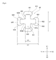
- It is a top view which shows the structure of the main body part of the electric chain block shown in FIG.
- the Z direction refers to the direction in which the load chain C1 is suspended
- the Z1 side refers to the side on which the upper hook 70 is located
- the lower hook 80 opposite to the Z2 side is located.
- the Z1 side refers to the upper side and the Z2 side refers to the lower side.
- the X direction refers to the longitudinal direction of the main body 20, the X1 side refers to the upper right side in FIG. 1, and the X2 side refers to the opposite lower left side.
- the Y direction refers to a direction orthogonal to the Z direction and the X direction, the Y1 side refers to the right side in FIG. 1, and the Y2 side refers to the opposite left side.
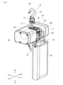
- FIG. 1 is a perspective view showing a configuration of an electric chain block 10 according to an embodiment of the present invention.
- FIG. 2 is a perspective view showing a state of being suspended upside down in the electric chain block 10 shown in FIG.
- FIG. 3 is a cross-sectional view showing the configuration of the electric chain block 10 shown in FIG. 1 in the vicinity of the load sheave 22.
- the electric chain block 10 includes a main body 20, an upper hook 70, a lower hook 80, a chain bucket 90, and a bucket mounting bracket 100.
- the electric chain block 10 of the present embodiment is a type capable of both normal suspension and upside-down suspension.
- the main body 20 has a body 30, a motor 40, a load sheave 50, and a guide member 60 as main components.
- the body 30 and the guide member 60 are integrally fixed with bolts or the like to form one housing.
- the body 30 is formed of, for example, an aluminum-based metal or an iron-based metal. As shown in FIG. 3, the body 30 has a portion forming an outer surface such as a side surface 31 and a top surface 32, and a structural portion existing inside the outer surface. Further, although the portion of the body 30 to which the guide member 60 to be attached, which will be described later, is recessed from the outer surface, when the guide member 60 is attached to the body 30, the main body portion 20 in a state where there is almost no recess is configured. There is.
- a guide member 60 for guiding the feed of the load chain C1 is also attached to the body 30.
- the guide member 60 is a separate part from the body 21, but the guide member 60 may be integrated with the body 30 (it may be the same part as the body 30). The details of the configuration of the guide member 60 will be described later.
- the road sheave 50 is provided with a plurality of chain pockets 51, and the metal ring of the road chain C1 can be fitted into the chain pockets 51. Therefore, the load chain C1 can be hoisted and unwound by driving the motor 40.
- an upper hook 70 is attached to the body 30 via a connecting shaft S1 that is inserted into the shaft hole 34 of the body 30.
- the upper hook 70 includes a hook portion 71 and a hook receiving portion 72.
- the hook portion 71 is a portion for hanging luggage, a ceiling, or the like.
- the hook receiving portion 72 is a portion that rotatably supports the hook portion 71.
- the hook receiving portion 72 is provided with a mounting hole 72a that penetrates the hook receiving portion 72 in the Y direction, and the connecting shaft S1 is inserted into the mounting hole 72a.
- the upper hook 70 is supported by the main body portion 20 (body 30) via the connecting shaft S1.
- the lower hook 80 includes a base 81, and the base 81 is connected to the lower end side (Z2 side) of the load chain C1 sent out from the chain entrance / exit 611 (described later) of the first guide passage 610 of the guide member 60. Further, the lower hook 80 includes a hook portion 82 for loading a load, and the hook portion 82 is attached to the base portion 81 in a rotatably state.
- the lower hook 80 collides with the bottom surface 33 of the body 30, and at that time, the limit switch 120 described later is pushed in. As a result, the driving of the motor 40 can be stopped and the hoisting of the lower hook 80 can be stopped.
- the chain bucket 90 is a bucket-shaped portion for accommodating the load chain C1 discharged from the side chain entrance / exit 651, which will be described later.
- the chain bucket 90 is made of a resin or cloth that is flexible enough to withstand the weight of the load chain C1.
- the chain bucket 90 is attached to the bucket mounting bracket 100 via a carabiner, a wire, or other connecting tool 110. Therefore, the chain bucket 90 is in a state of being attached to the main body 20 (body 30 and guide member 60) via the connector 110 and the bucket mounting bracket 100.
- the bucket mounting bracket 100 has a bucket mounting portion 105.
- the bucket mounting portion 105 is a portion to which the chain bucket 90 is mounted via the connector 110.
- the bucket mounting portion 105 includes a substantially U-shaped mounting arm 105a protruding from the side surface 31 side, and the insertion portion of the connector 110 is inserted into the mounting hole 105b surrounded by the mounting arm 105a. be able to.
- the mounting hole 105b has a predetermined length along the Z direction (that is, it has an elongated hole shape along the Z direction). Then, at the time of normal suspension, the connector 110 is located on the Z2 side (lower side) of the attachment hole 105b, and the chain bucket 90 can be attached via the connector 110. On the other hand, in the case of upside-down suspension, the connector 110 is located on the Z1 side (upper side in normal suspension) of the attachment hole 105b, and the chain bucket 90 can be attached via the connector 110. Therefore, in both the normal suspension and the upside-down suspension, the load chain C1 that hangs down due to its own weight can be satisfactorily stored in the chain bucket 90.
- the guide member 60 together with the body 30 described above, constitutes a structural portion of the main body portion 20.
- the guide member 60 is provided so as to be close to the load sheave 50 at predetermined positions (first position and second position). As a result, the load chain C1 is fed out while being well fitted in the chain pocket 51 located within the predetermined angle range inside the body 30.
- the guide member 60 is made of a metal block body having wear resistance and strength such as carbon steel and alloy steel.
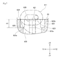
- FIG. 4 is a perspective view showing the configurations of the load sheave 50, the arc-shaped covering member 67, and the limit switch 120 centering on the guide member 60.
- the guide member 60 is provided with a first guide passage 610 and a second guide passage 650.
- the first guide passage 610 is a portion that satisfactorily guides the movement of the load chain C1 extending toward the lower hook 80 side (Z2 side).
- the side of the first guide passage 610 where the load chain C1 enters and exits is referred to as a chain entrance / exit 611
- the side of the second guide passage 650 where the load chain C1 enters and exits is referred to as a side chain entrance / exit 651.
- FIG. 5 is a partial perspective view showing the configuration of the main body 20 in the vicinity of the chain entrance / exit 611.
- FIG. 6 is a plan view showing the configuration of the main body 20 in the vicinity of the chain entrance / exit 611.
- FIG. 7 is a cross-sectional view showing the configuration of the main body portion 20 in the vicinity of the chain entrance / exit 611, and is a view showing a state of being cut along the first lateral groove.
- the chain entrance / exit 611 is provided with a first guide groove 620 and a second guide groove 630.
- the first guide groove 620 is a portion provided on the opening side of the chain entrance / exit 611 with respect to the second guide groove 630. That is, although the first guide groove 620 and the second guide groove 630 are connected to each other, the first guide groove 620 exists on the opening side of the chain entrance / exit 611, and the main body portion 20 is more than the first guide groove 620.
- the first guide groove 620 is provided with a first vertical groove 621 and a first horizontal groove 622, which intersect at right angles (that is, at the first vertical groove 621 and the first horizontal groove 622). It is provided in a cross shape).
- the length L1 of the first vertical groove 621 and the first horizontal groove 622 corresponds to the length in the longitudinal direction of each link C1a of the load chain C1.
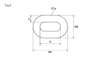
- FIG. 8 is a plan view showing the link C1a. As shown in FIG. 8, when the length of the link C1a in the longitudinal direction is M1, the length L1 of the first vertical groove 621 and the first horizontal groove 622 is provided so as to be larger than the length M1. ..
- the groove width L2 of the first vertical groove 621 (referred to as the groove width L21) is the first horizontal groove 622. It is preferable that the groove width is larger than the groove width L2 (the groove width L22). This is because the line connecting the chain pockets 51 of the load sheave 50 is polygonal, so that the link C1a slightly sways (vibrates) in the Y direction as the load sheave 50 rotates.
- first vertical groove 621 and the first horizontal groove 622 are provided with a throttle portion 623.
- the throttle portion 623 is a portion facing the first vertical groove 621 and the first horizontal groove 622, and is provided with four as shown in FIG.
- the throttle portion 623 is provided with a tip portion 623a and a flat surface portion 623b.
- the tip portion 623a is provided so that the radius of curvature is smaller than the corner portion of the groove bulging portion 624, which will be described later, in order to limit the direction of the link C1a. It is preferable that the radius of curvature is set to the same radius of curvature as the throttle portion at the current chain entrance / exit.
- the radius of curvature of the tip portion 623a is set to be about the same as the radius of curvature of the current throttle portion of the chain entrance / exit without being larger than the groove bulging portion 624, so that the first vertical groove 621 or the first horizontal groove 622
- the direction of the inserted link C1a can be adjusted so as to be along either the first vertical groove 621 or the first horizontal groove 622.
- the link C1a is prevented from entering the inside of the first vertical groove 621 or the first horizontal groove 622 in a state where the link C1a cannot be arranged in either the direction of the first vertical groove 621 or the first horizontal groove 622.
- it is prevented that the winding failure in the road sheave 50 occurs.
- the flat surface portion 623b is a portion provided parallel to the longitudinal direction of the first vertical groove 621 or the first horizontal groove 622.
- the two flat surface portions 623b in each diaphragm portion 623 are provided so as to be orthogonal to each other. Since the flat surface portion 623b has a predetermined length, it is possible to prevent the tip portion 623a from being worn in a short period of time. Further, the space between the flat surfaces 623b facing each other corresponds to the groove width L2 in the first vertical groove 621 or the first horizontal groove 622.
- the diaphragm portion 623 is provided so as to be flush with the bottom surface 33. As a result, the wear resistance of the drawn portion 623 is improved.
- first vertical groove 621 and the first horizontal groove 622 are also provided with a groove bulging portion 624.
- the groove bulging portion 624 expands the groove width so as to have a larger interval than the groove width L2 at the portion of the first vertical groove 621 and the first horizontal groove 622 on the end side in the groove direction with respect to the throttle portion 623. This is the part that was done. Further, due to the presence of the groove bulging portion 624, the groove lengths of the first vertical groove 621 and the first horizontal groove 622 are extended to the groove length L1.
- the groove length L1 of the first vertical groove 621 and the first horizontal groove 622 becomes the second guide groove 630 described later. It is longer than the groove lengths of the two vertical grooves 631 and the second horizontal groove 632.
- the groove bulging portion 624 is a portion for inserting the leading portion of the link C1a in a state of being slightly inclined with respect to the groove direction of the first vertical groove 621 or the first horizontal groove 622 and slightly tilted from the standing state. ..
- the space SP preferably exists within a circle having a radius from the center of the chain entrance / exit 611 to the farthest end of the groove bulging portion 624.
- a step bottom surface portion 625 is provided on the back side (Z1 side) of the main body portion 20 of the first guide groove 620.
- the step bottom surface portion 625 is a portion that serves as a boundary with the second guide groove 630. That is, since the groove lengths of the first guide groove 620 and the second guide groove 630 are different by the amount of the groove bulging portion 624, the step bottom surface portion 625 as shown in FIG. 7 is formed.
- a link C1a (collision link) exists in any of the throttle portions 623 of the bottom surface 33, and the link C1a is used as a fulcrum.
- the adjacent links C1a adjacent links
- the depth H1 is set so that the links C1a (adjacent links) do not collide with the step bottom surface portion 625.
- the rotation of the link C1a that has entered the first guide groove 620 is not hindered by the step bottom surface portion 625, so that the stack of the load chain C1 can be released.
- an arc-shaped portion 625a is provided at a portion near the center of the chain entrance / exit 611. Therefore, even if the link C1a collides with the step bottom surface portion 625, the link C1a is smoothly guided to the second guide groove 630 side due to the presence of the arc-shaped portion 625a.
- the boundary portion between the first guide groove 620 and the second guide groove 630 may be provided in a curved shape as a whole.
- the second vertical groove 631 existing in the second guide groove 630 corresponds to the length M2 in the lateral direction of the link C1a, but the width M2 is necessary and sufficient for the guide of the link C1a.
- the second lateral groove 632 existing in the second guide groove 630 also corresponds to the length M2 in the lateral direction of the link C1a, but the width M2 is necessary and sufficient for the guide of the link C1a. There is. When the link C1a enters the second vertical groove 631 or the second horizontal groove 632, the direction of the link C1a is further adjusted.
- the limit switch 120 is a mechanical switch that the lower hook 80 can be pushed in.
- the push-in portion 121 of the limit switch 120 projects from the bottom surface 33, and the push-in portion 121 is provided within a range where the lower hook 80 collides. It is preferable that at least a part of the push-in portion 121 approaches the space SP described above.
- a protective cover 130 is attached to a portion of the guide member 60 where the limit switch 120 is arranged.
- FIG. 9 is a diagram showing an example in which a stack is generated in the load chain C1 around the current chain entrance / exit 611B.
- the chain entrance / exit 611B shown in FIG. 9 has a vertical groove 641B and a horizontal groove 642B having a constant groove width.
- the link C1a that has already entered the chain entrance / exit 611B (horizontal groove 642B in FIG. 9) is referred to as the first link C11a
- the link C1a connected to the first link C11a is referred to as the second link C12a
- another link C1a connected to the second link C12a is referred to as a third link C13a.
- the second link C12a collides with the point P of the bottom surface 33 near the chain entrance / exit 611, and the third link C13a collides with the periphery of the chain entrance / exit 611, the second link C13a is brought along with the rotation of the load sheave 50.
- the 2nd link C12a tries to rotate to the side where the bottom surface 33 is pushed (the arrow F side in FIG. 9).
- the second link C12a since the third link C13a collides with the bottom surface 33 near the chain entrance / exit 611 as shown by the circular alternate long and short dash line in FIG. 7, the second link C12a has the third link C13a side from the bottom surface 33. It is inclined so as to be in contact with the bottom surface 33 at a point P on the side away from the third link C13a. Therefore, when the second link C12a is pulled in by the first link C11a, the second link C12a is rotated so as to further push the point P into the bottom surface 33 (that is, around the arrow F).
- FIG. 10 is a diagram showing an image in which the stack of the load chain C1 around the chain entrance / exit 611 is eliminated by the presence of the groove bulging portion 624.
- the groove bulging portion 624 is provided, so that the above-mentioned point P does not exist on the bottom surface 33 but exists on the groove bulging portion 624. It will be in a state of doing.
- the second link C12a is in a state in which the leading side of the pull-in has entered the first vertical groove 621 or the first horizontal groove 622. Therefore, when the second link C12a is pulled in by the first link C11a, the second link C12a changes its direction without causing a relocation that hinders rotation as in the case where the point P exists on the bottom surface 33. Can be done.
- each link C1a can be smoothly pulled into the chain entrance / exit 611.
- the main body 20 including the motor 40 and the load sheave 50 and the chain inlet / outlet 611 provided on the bottom surface 33 of the main body 20 to allow the load chain C1 on the load side to enter and exit are provided.
- the chain entrance / exit 611 has a first guide groove 620, and the first guide groove 620 is provided on the opening side of the chain entrance / exit 611 and is the length of each link C1a of the load chain C1.
- a first vertical groove 621 and a first horizontal groove 622 having a groove length corresponding to the length in the direction are provided, and the first vertical groove 621 and the first horizontal groove 622 intersect at right angles.
- the chain entrance / exit 611 has a second guide groove 630
- the second guide groove 630 is provided on the back side of the main body 20 with respect to the first guide groove 620
- the load chain C1 has a second guide groove 630.
- a second vertical groove 631 and a second horizontal groove 632 having a groove length corresponding to the length of each link C1a in the lateral direction are provided, and the second vertical groove 631 and the second horizontal groove 632 are orthogonal to each other. Crosses over.
- the first guide groove 620 faces each other with a groove width L2 corresponding to the wire diameter of the link C1a of the load chain C1 in the width direction of the first vertical groove 621, and the groove width in the width direction of the first horizontal groove 622. By facing each other across L2, it has a throttle portion 623 that defines whether to be introduced into the first vertical groove 621 or the first horizontal groove 622 when each link C1a of the load chain C1 is pulled in. .. Further, the first guide groove 620 is provided on the outside of the throttle portion 623 away from the center of the chain entrance / exit 611, and has a groove bulging portion 624 having a width larger than the groove width L2.
- the leading side of the second link C12a can be inserted into the groove bulging portion 624 as described with reference to FIG. 10 above. Therefore, it is prevented that the second link C12a collides with the bottom surface 33 at the point P as shown in FIG. You can get in.
- the direction of the second link C12a is changed without causing a change that hinders rotation as in the case where the point P exists on the bottom surface 33. be able to. Therefore, after the orientation of the second link C12a is changed, each link C1a can be smoothly pulled into the chain entrance / exit 611. Therefore, even if the link C1a is laid down or tilted, the link C1a can be easily entered into the chain entrance / exit 611.
- the orientation of the link C1a can be limited by the throttle portion 623. That is, the direction of the link C1a that has entered the first vertical groove 621 or the first horizontal groove 622 can be adjusted so as to be along either the first vertical groove 621 or the first horizontal groove 622. As a result, the link C1a is prevented from entering the inside of the first vertical groove 621 or the first horizontal groove 622 in a state where the link C1a cannot be arranged in either the direction of the first vertical groove 621 or the first horizontal groove 622. As a result, it is possible to prevent the load sheave 50 from being poorly wound.
- the chain entrance / exit 611 since the chain entrance / exit 611 has a throttle portion 623 and a groove bulging portion 624, it is not necessary to form a protruding portion with respect to the bottom surface 33. Therefore, when the lower hook 80 collides with the bottom surface 33 near the chain entrance / exit 611, the pushing portion 121 of the limit switch 120 can be easily pushed.
- the link C1a drawn into the first vertical groove 621 or the first horizontal groove 622 reaches the inside of the second guide groove 630 with the link C1a (second link C12a) in contact with the bottom surface 33 as a fulcrum.
- the first vertical groove 621 and the first horizontal groove 622 are formed at a depth that allows them to rotate so as to be inverted.
- the link C1a connected to the link C1a is connected to the link C1a with the link C1a colliding with the bottom surface 33 near the chain entrance / exit 611 as a fulcrum.
- the adjacent link can be rotated so as to reach the inside of the second guide groove 630 and be inverted while being inserted into the first guide groove 620.
- the rotation of the link C1a that has entered the first guide groove 620 is not hindered, so that the stack of the load chain C1 can be released.
- the diaphragm portion 623 is provided so as to be flush with the bottom surface 33 and to be connected to the bottom surface 33. Therefore, it is possible to give sufficient strength to the drawing portion 623 and improve the wear resistance of the drawing portion 623.
- the pushing portion 121 of the limit switch 120 is arranged in the space SP located within the range where the base 81 of the lower hook 80 collides with the bottom surface 33 near the chain entrance / exit 611. There is. Then, by pushing the pushing portion 121, the driving of the motor 40 is stopped.
- the chain entrance / exit 611 on the lower hook 80 side is described.
- the side chain entrance / exit 651 also has a first guide groove similar to the first guide groove 620 having the above-mentioned throttle portion and a groove bulging portion, and a second guide groove similar to the second guide groove 630 located on the back side thereof. It may be provided with two guide grooves.
- the diaphragm portion 623 is provided so as to be flush with the bottom surface 33.
- the throttle portion 623 may not be flush with the bottom surface 33, and may be slightly protruded or slightly recessed within a range that does not hinder the pushing of the pushing portion 121.
Landscapes
- Engineering & Computer Science (AREA)
- Mechanical Engineering (AREA)
- Devices For Conveying Motion By Means Of Endless Flexible Members (AREA)
- Refuge Islands, Traffic Blockers, Or Guard Fence (AREA)
- Operating, Guiding And Securing Of Roll- Type Closing Members (AREA)
- Load-Engaging Elements For Cranes (AREA)
Priority Applications (3)
| Application Number | Priority Date | Filing Date | Title |
|---|---|---|---|
| JP2022505776A JP7305868B2 (ja) | 2020-03-09 | 2020-12-23 | 電気チェーンブロック |
| US17/910,360 US12103829B2 (en) | 2020-03-09 | 2020-12-23 | Electric chain block |
| CN202080097311.8A CN115151506A (zh) | 2020-03-09 | 2020-12-23 | 电动链式葫芦 |
Applications Claiming Priority (2)
| Application Number | Priority Date | Filing Date | Title |
|---|---|---|---|
| JP2020040047 | 2020-03-09 | ||
| JP2020-040047 | 2020-03-09 |
Publications (1)
| Publication Number | Publication Date |
|---|---|
| WO2021181820A1 true WO2021181820A1 (ja) | 2021-09-16 |
Family
ID=77671539
Family Applications (1)
| Application Number | Title | Priority Date | Filing Date |
|---|---|---|---|
| PCT/JP2020/048078 Ceased WO2021181820A1 (ja) | 2020-03-09 | 2020-12-23 | 電気チェーンブロック |
Country Status (5)
| Country | Link |
|---|---|
| US (1) | US12103829B2 (https=) |
| JP (1) | JP7305868B2 (https=) |
| CN (1) | CN115151506A (https=) |
| TW (1) | TWI878470B (https=) |
| WO (1) | WO2021181820A1 (https=) |
Families Citing this family (3)
| Publication number | Priority date | Publication date | Assignee | Title |
|---|---|---|---|---|
| DE112020005069T5 (de) * | 2019-10-21 | 2022-07-21 | Kito Corporation | Hebezeug |
| WO2021181846A1 (ja) * | 2020-03-09 | 2021-09-16 | 株式会社キトー | 電気チェーンブロック |
| US12460980B2 (en) * | 2020-12-11 | 2025-11-04 | Kito Corporation | Upper and lower limit detecting apparatus and method for electric chain block |
Citations (7)
| Publication number | Priority date | Publication date | Assignee | Title |
|---|---|---|---|---|
| JPS4838677Y1 (https=) * | 1970-04-21 | 1973-11-15 | ||
| JPS4935093Y1 (https=) * | 1969-08-22 | 1974-09-24 | ||
| JPS55180698U (https=) * | 1979-06-11 | 1980-12-25 | ||
| JPS56161297A (en) * | 1980-05-16 | 1981-12-11 | Futaba Mfg | Smoothing flowing device for road chain of motor chain block |
| JPS56170193U (https=) * | 1980-05-16 | 1981-12-16 | ||
| JPS6360576U (https=) * | 1986-10-07 | 1988-04-22 | ||
| EP0692447A1 (en) * | 1994-07-15 | 1996-01-17 | Javier Amenabar Axpe | Hoist |
Family Cites Families (9)
| Publication number | Priority date | Publication date | Assignee | Title |
|---|---|---|---|---|
| US3289626A (en) * | 1965-08-19 | 1966-12-06 | Mcdermott & Co J Ray | Chain stoppers |
| DE1228384B (de) * | 1965-09-24 | 1966-11-10 | Demag Zug Gmbh | Kettenfuehrung mit kreuzfoermig angeordneten Fuehrungsnuten fuer Rundstahlketten |
| JPS4941780B1 (https=) | 1970-12-31 | 1974-11-11 | ||
| JPS5531896B2 (https=) * | 1972-08-01 | 1980-08-21 | ||
| US5007617A (en) * | 1989-08-03 | 1991-04-16 | Vital Kogyo Kabushiki Kaisha | Hand-operated chain block |
| DE102012112329B4 (de) | 2012-12-14 | 2020-04-23 | Konecranes Global Corp. | Kettenzug mit verbessertem Ketteneinlauf |
| CN206645741U (zh) * | 2017-04-17 | 2017-11-17 | 维多利科技(江苏)有限公司 | 一种具有自适应链条环限位装置的手动葫芦 |
| DE102019118225B3 (de) * | 2019-07-05 | 2020-10-01 | Rud Ketten Rieger & Dietz Gmbh U. Co. Kg | Kettenantriebssystem |
| CN110282567B (zh) * | 2019-07-09 | 2021-05-28 | 浙江冠林机械有限公司 | 一种手拉葫芦 |
-
2020
- 2020-12-23 CN CN202080097311.8A patent/CN115151506A/zh active Pending
- 2020-12-23 JP JP2022505776A patent/JP7305868B2/ja active Active
- 2020-12-23 WO PCT/JP2020/048078 patent/WO2021181820A1/ja not_active Ceased
- 2020-12-23 US US17/910,360 patent/US12103829B2/en active Active
-
2021
- 2021-02-25 TW TW110106652A patent/TWI878470B/zh active
Patent Citations (7)
| Publication number | Priority date | Publication date | Assignee | Title |
|---|---|---|---|---|
| JPS4935093Y1 (https=) * | 1969-08-22 | 1974-09-24 | ||
| JPS4838677Y1 (https=) * | 1970-04-21 | 1973-11-15 | ||
| JPS55180698U (https=) * | 1979-06-11 | 1980-12-25 | ||
| JPS56161297A (en) * | 1980-05-16 | 1981-12-11 | Futaba Mfg | Smoothing flowing device for road chain of motor chain block |
| JPS56170193U (https=) * | 1980-05-16 | 1981-12-16 | ||
| JPS6360576U (https=) * | 1986-10-07 | 1988-04-22 | ||
| EP0692447A1 (en) * | 1994-07-15 | 1996-01-17 | Javier Amenabar Axpe | Hoist |
Also Published As
| Publication number | Publication date |
|---|---|
| JPWO2021181820A1 (https=) | 2021-09-16 |
| JP7305868B2 (ja) | 2023-07-10 |
| US12103829B2 (en) | 2024-10-01 |
| TWI878470B (zh) | 2025-04-01 |
| TW202134166A (zh) | 2021-09-16 |
| US20230138172A1 (en) | 2023-05-04 |
| CN115151506A (zh) | 2022-10-04 |
Similar Documents
| Publication | Publication Date | Title |
|---|---|---|
| WO2021181820A1 (ja) | 電気チェーンブロック | |
| CN107344686B (zh) | 具有耐磨板的混合导缆器 | |
| JP4840256B2 (ja) | カウンタバランス型クレーン | |
| EP2042462B1 (en) | Elevator apparatus | |
| JP6435281B2 (ja) | 電動ホイスト | |
| TWI878465B (zh) | 電動鏈吊車 | |
| JP6296102B2 (ja) | 移動式クレーンのガイラインとパレットウエイトとの接続方法及び移動式クレーン | |
| CN104787642B (zh) | 电梯设备 | |
| JP6985644B2 (ja) | フック | |
| JP6869579B1 (ja) | 回転機械・ベース組立体、ベース、及び、吊り上げ方法 | |
| JP4586735B2 (ja) | 部品整列供給装置 | |
| EP3922590A1 (en) | Auxiliary cylinder apparatus, working machine including same, and use of auxiliary cylinder | |
| JP6686264B2 (ja) | 電動ホイスト | |
| JP4498759B2 (ja) | エレベータ装置 | |
| JP6987697B2 (ja) | 捩じれ検出装置およびチェーンブロック | |
| JP6803008B2 (ja) | エレベータ | |
| JP2008260595A (ja) | エレベータの主索ブレーキ装置 | |
| JP6568000B2 (ja) | クレーン機能付き作業機械 | |
| JP4674938B2 (ja) | ジブクレーン | |
| KR20130002909U (ko) | 굴삭기용 인양장치 | |
| JP4053555B2 (ja) | リーダ | |
| KR102302690B1 (ko) | 화물엘리베이터의 카박스와 로프 연결장치 | |
| JP4630860B2 (ja) | 杭打機 | |
| JP2002137877A (ja) | エレベータ用移動ケーブルの保護装置 | |
| JP5237200B2 (ja) | 杭打機 |
Legal Events
| Date | Code | Title | Description |
|---|---|---|---|
| 121 | Ep: the epo has been informed by wipo that ep was designated in this application |
Ref document number: 20924094 Country of ref document: EP Kind code of ref document: A1 |
|
| ENP | Entry into the national phase |
Ref document number: 2022505776 Country of ref document: JP Kind code of ref document: A |
|
| NENP | Non-entry into the national phase |
Ref country code: DE |
|
| 122 | Ep: pct application non-entry in european phase |
Ref document number: 20924094 Country of ref document: EP Kind code of ref document: A1 |