WO2021181759A1 - 保持装置および部品装着システム - Google Patents
保持装置および部品装着システム Download PDFInfo
- Publication number
- WO2021181759A1 WO2021181759A1 PCT/JP2020/043508 JP2020043508W WO2021181759A1 WO 2021181759 A1 WO2021181759 A1 WO 2021181759A1 JP 2020043508 W JP2020043508 W JP 2020043508W WO 2021181759 A1 WO2021181759 A1 WO 2021181759A1
- Authority
- WO
- WIPO (PCT)
- Prior art keywords
- unit
- holding
- switching
- reading
- identification information
- Prior art date
- Legal status (The legal status is an assumption and is not a legal conclusion. Google has not performed a legal analysis and makes no representation as to the accuracy of the status listed.)
- Ceased
Links
Images


Classifications
-
- H—ELECTRICITY
- H05—ELECTRIC TECHNIQUES NOT OTHERWISE PROVIDED FOR
- H05K—PRINTED CIRCUITS; CASINGS OR CONSTRUCTIONAL DETAILS OF ELECTRIC APPARATUS; MANUFACTURE OF ASSEMBLAGES OF ELECTRICAL COMPONENTS
- H05K13/00—Apparatus or processes specially adapted for manufacturing or adjusting assemblages of electric components
- H05K13/02—Feeding of components
Definitions
- the present disclosure relates to a holding device and a component mounting system used to mount a component on a substrate.
- the component mounting device includes a trolley which is an example of a holding device and a plurality of feeders held by the trolley, and mounts parts such as electronic parts supplied by the feeders on the substrate.
- the feeder is fitted with a container for accommodating component tapes for accommodating a plurality of components.
- the container is a reel, and a component tape is wound around the reel. The feeder feeds out the component tape from the reel to sequentially supply a plurality of components stored in the component tape.
- a reel with an RFID (Radio Frequency Identifier) tag attached is attached to this electronic component supply feeder, and a reader / writer that reads the identification information of the reel from the RFID tag is also arranged. This makes it possible to manage the container which is a reel.
- RFID Radio Frequency Identifier
- Patent Document 1 Even if the electronic component supply feeder of Patent Document 1 is held by a trolley which is a holding device, there is a problem that it is difficult to properly manage the electronic component supply feeder. For example, when a plurality of electronic component supply feeders are held by the trolley, it is difficult to grasp which electronic component supply feeder is held at which position on the trolley.
- the present disclosure provides a holding device and the like capable of appropriately managing the feeder and the container.
- the holding device is a holding device used for a device for mounting a component on a substrate, and a plurality of first holding portions for holding a feeder for supplying each component and each component are housed in the holding device.
- the identification information of the feeder arranged in each of the plurality of second holding portions for holding the container for accommodating the parts tape and the plurality of first holding portions and held in the first holding portion is read.
- a first reading unit and a second reading unit arranged in each of the plurality of second holding units and reading the identification information of the container held in the second holding unit are provided.
- a recording medium such as a system, method, integrated circuit, computer program or computer-readable CD-ROM, and the system, method, integrated circuit, computer program. And may be realized by any combination of recording media. Further, the recording medium may be a non-temporary recording medium.
- the holding device of the present disclosure can properly manage the feeder and the container.
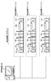
- FIG. 1 is a diagram showing an example of a configuration of a component mounting system according to an embodiment.
- FIG. 2 is a diagram showing an example of the configuration of the component mounting device according to the embodiment.
- FIG. 3 is a schematic view showing the positional relationship between the mounting head and the feeder in the embodiment.
- FIG. 4 is an external view showing the appearance of the electronic component to be mounted according to the embodiment.
- FIG. 5 is a diagram showing an example of a reel around which a component tape is wound according to the embodiment.
- FIG. 6 is a diagram partially showing an example of a cross section taken along the line VI-VI in FIG.
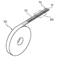
- FIG. 7 is a diagram showing an example of a tape roll body in the embodiment.
- FIG. 8 is a partially enlarged view of the tape roll body shown in FIG. 7 in the region AR.
- FIG. 9 is a diagram showing an example of a tape box for accommodating a tape roll body according to the embodiment.
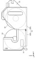
- FIG. 10 is a diagram partially showing an example of a cross section of a component mounting device using a tape box according to the embodiment.
- FIG. 11 is a block diagram showing an example of the respective configurations of the dolly and the component mounting device main body included in the component mounting system according to the embodiment.
- FIG. 12 is a block diagram showing another example of the respective configurations of the dolly and the component mounting device main body included in the component mounting system according to the embodiment.
- FIG. 13 is a diagram showing an example of a processing operation by the determination unit in the embodiment.
- FIG. 14 is a flowchart showing an example of the processing operation of the dolly according to the embodiment.
- FIG. 15 is a flowchart showing an example of the processing operation of the component mounting device main body in the embodiment.
- FIG. 16 is a flowchart showing another example of the processing operation of the dolly according to the embodiment.
- the holding device is a holding device used for a device for mounting a component on a substrate, and a plurality of positions for holding a feeder for supplying the component. It is arranged in each of one holding portion, a plurality of second holding portions for holding a container for accommodating component tapes in which parts are stored, and the plurality of first holding portions, and is held by the first holding portion.
- the holding device may be a trolley.
- the identification information of the feeder held in the first holding unit is read by the first reading unit of each first holding unit. Therefore, it is possible to appropriately specify what kind of feeder is held in any of the first holding portions among the plurality of first holding portions.
- the identification information of the container held in the second holding part is read by the second reading part of each second holding part. Therefore, it is possible to appropriately specify what kind of container is held in any of the second holding parts of the plurality of second holding parts. As a result, a plurality of feeders and a plurality of containers can be properly managed.
- the holding device further includes a plurality of the first reading units arranged in the plurality of first holding units and a plurality of the second reading units arranged in the plurality of second holding units, respectively.
- a switching unit for sequentially selecting one of the first reading units or the second reading unit as a switching target reading unit from the plurality of the first reading units and the plurality of the second reading units is provided. Each time the switching target reading unit is selected by switching, the switching unit may acquire and output the identification information read by the selected switching target reading unit from the switching target reading unit.
- the identification information is read and output in order from each of the plurality of first reading units and the plurality of second reading units. Therefore, the position where the switching target reading unit which is the first reading unit or the second reading unit that has read the output identification information is arranged, that is, the first holding unit or the second holding unit where the switching target reading unit is located.
- the position of can be specified. As a result, it is possible to more appropriately identify what kind of feeder or what kind of container is held in the first holding part or the second holding part at which position.
- the holding device may further include a switching control unit that controls switching by the switching unit.
- the switching control unit acquires the identification information read by the switching target reading unit via the switching unit, and reads the position information indicating the position where the switching target reading unit is arranged. It may be associated with the identification information.
- a first tag indicating the identification information of the feeder is attached to each of the plurality of feeders
- a second tag indicating the identification information of the container is attached to each of the plurality of containers.
- the first reading portion arranged in the first holding portion is from the first tag of the feeder held in the first holding portion to the feeder.
- the identification information is read, and in each of the plurality of second holding portions, the second reading portion arranged in the second holding portion is the second tag of the container held in the second holding portion.
- the identification information of the container may be read from.
- each of the plurality of the first reading units reads the identification information of the feeder from the first tag in a state of being close to the first tag corresponding to the first reading unit
- the plurality of said Each of the second reading units may read the identification information of the container from the second tag in a state of being close to the second tag corresponding to the second reading unit.
- each of the plurality of the first reading portions arranged in the plurality of first holding portions and the plurality of the second reading portions arranged in the plurality of second holding portions each have a linear conductor. It may be included.
- the first tag attached to each of the plurality of feeders and the second tag attached to each of the plurality of containers may be RFID (Radio Frequency Identifier) tags. ..
- the identification information can be appropriately read from each feeder and each tag of each container. can.
- the switching target reading unit may be connected to the switching unit via a wire.
- the identification information can be easily and accurately output from the switching target reading unit to the switching unit.
- the switching target reading unit may be connected to the switching unit via wireless communication.
- the holding device is further arranged in the identification information of the feeder read by the first reading unit arranged in each of the plurality of first holding units and in each of the plurality of second holding units.
- a first communication unit may be provided which transmits the identification information of the container read by the second reading unit to an external device outside the holding device.
- the external device may be, for example, a component mounting device main body or a management device, and may be a device called a host device.
- the container may be a reel that houses the component tape in a wound state.
- the container may be a tape box for accommodating the component tape.
- the component mounting system includes the above-mentioned holding device and a component mounting device main body for mounting the component on a substrate, and the component mounting device main body includes the plurality of first holding portions.
- the identification information of the feeder read by the first reading unit arranged in each, and the identification information of the container read by the second reading unit arranged in each of the plurality of second holding units.
- the production data acquisition unit that acquires the production data related to the feeder and the container required for mounting the components on the board, and the acquired production data
- the second communication unit It includes a determination unit for determining the suitability of each identification information of the feeder and the container received by the communication unit.
- the holding device further includes a plurality of the first reading units arranged in the plurality of first holding units and a plurality of the second reading units arranged in the plurality of second holding units, respectively.
- a switching unit for sequentially selecting one of the first reading units or the second reading unit as a switching target reading unit from the plurality of the first reading units and the plurality of the second reading units is provided. Each time the switching target reading unit is selected by switching, the switching unit acquires and outputs the identification information read by the selected switching target reading unit from the switching target reading unit, and outputs the component mounting device.
- the main body may further include a switching control unit that controls switching by the switching unit.
- the plurality of first reading units and the plurality of second reading units can be switched in the component mounting device main body, and the processing load of switching in the holding device can be reduced, for example.
- the holding device further includes a plurality of the first reading units arranged in the plurality of first holding units and a plurality of the second reading units arranged in the plurality of second holding units, respectively.
- a switching unit for sequentially selecting one of the first reading units or the second reading unit as a switching target reading unit from the plurality of the first reading units and the plurality of the second reading units is provided. Each time the switching target reading unit is selected by switching, the switching unit acquires and outputs the identification information read by the selected switching target reading unit from the switching target reading unit, and outputs the component mounting system.
- the management device may include a management device for managing the holding device and the component mounting device including the component mounting device main body, and the management device may include a switching control unit for controlling switching by the switching unit.
- the management device can switch between the plurality of first reading units and the plurality of second reading units, and for example, the processing load of switching in the holding device and the component mounting device main body can be reduced.
- each figure is a schematic view and is not necessarily exactly illustrated. Further, in each figure, the same components are designated by the same reference numerals.
- FIG. 1 is a diagram showing an example of a configuration of a component mounting system according to the present embodiment.
- the component mounting system 1 in the present embodiment includes three component mounting lines L1 to L3 and a management device 100.
- Each of the component mounting lines L1 to L3 produces a mounting board by performing solder printing work, component mounting work, reflow work, etc. on the board carried in from the upstream side, and the produced mounting board is placed on the downstream side. Carry out to.
- the management device 100 generates and outputs production data for producing a mounting board for each of the component mounting lines L1 to L3.
- the management device 100 communicates with those component mounting lines L1 to L3 via wireless or wired.
- the radio may be Wi-Fi®, Bluetooth®, ZigBee, or a specified low power radio.
- the component mounting line L1 includes a board supply device M1, a board delivery device M2, a solder printing device M3, component mounting devices M4 and M5, a reflow device M6, and a board recovery device M7.
- the devices included in the component mounting line L1 are arranged in the order of the board supply device M1, the board delivery device M2, the solder printing device M3, the component mounting devices M4 and M5, the reflow device M6, and the board recovery device M7, and are arranged in series. It is connected.
- each of these devices is hereinafter referred to as a working device.
- the component mounting line L1 may not include all of the above working devices as long as it includes the board supply device M1, at least one component mounting device, and the board recovery device M7. Further, the component mounting line L1 may include, in addition to the above-mentioned working device, a solder coating device for applying solder to the substrate, a component insertion machine for mounting radial components or axial components on the substrate, and the like.
- the board supply device M1 supplies the board used for the mounting board produced on the component mounting line L1 to the solder printing device M3 via the board delivery device M2.
- the solder printing apparatus M3 performs the above-mentioned solder printing operation. That is, the solder printing device M3 screen-prints the solder on the board delivered from the board delivery device M2.
- Each of the component mounting devices M4 and M5 executes the above-mentioned component mounting operation for mounting at least one component on the board.
- the component mounting line L1 includes two component mounting devices M4 and M5, but the number of the component mounting devices M4 and M5 is not limited to two, and may be one or three or more. Further, it can be said that the mounting board is substantially produced by the component mounting work by these component mounting devices M4 and M5.
- the reflow device M6 performs the above-mentioned reflow work. That is, the reflow device M6 heats the substrate on which the component is mounted, which is carried in from the component mounting devices M4 and M5, cures the solder on the substrate, and joins the electrode portion of the substrate and the component. Specifically, the reflow device M6 melts and solidifies the solder for joining parts by heating according to a predetermined heating profile. As a result, the components are soldered to the substrate.
- the substrate recovery device M7 recovers the solder-bonded substrate from the reflow device M6.
- the component mounting lines L2 and L3 also have the same configuration as the component mounting line L1.
- the component mounting lines L1 to L3 each have the same configuration, but may have different configurations from each other.
- FIG. 2 is a diagram showing an example of the configuration of the component mounting device M4.
- the component mounting device M5 also has the same configuration as the component mounting device M4.
- the transport direction of the substrate B is referred to as the X-axis direction
- the direction perpendicular to the X-axis direction is referred to as the Y-axis direction.
- the X-axis direction and the Y-axis direction are directions along the horizontal plane.
- the direction perpendicular to the X-axis direction and the Y-axis direction is referred to as a Z-axis direction.
- the plus side and minus side in the X-axis direction are the downstream side and the upstream side in the transport direction of the substrate B, respectively, and the plus side and the minus side in the Y-axis direction are the rear side (or the back side) and the front side (or the back side) in the front-rear direction, respectively. Or the front side).
- the positive side and the negative side in the Z-axis direction are the upper side and the lower side in the vertical direction, respectively.
- the upper surface of the component mounting device M4 is shown.
- the component mounting device M4 includes a base 4, a board transfer mechanism 5, two component supply units 6, two X-axis beams 9, a Y-axis beam 8, two mounting heads 10, and two component recognitions. It includes a camera 11 and two board recognition cameras 12.
- the board transfer mechanism 5 is provided with two rails along the X-axis direction and is arranged in the center of the base 4.
- the board transport mechanism 5 transports the board B carried in from the upstream side, and positions and holds the board B at a position for executing the component mounting operation.
- the two component supply units 6 are arranged so as to sandwich the substrate transfer mechanism 5 in the Y-axis direction.
- a plurality of feeders 7 are arranged in parallel along the X-axis direction in each component supply unit 6.
- the feeder 7 supplies the component to a position where the component is taken out by the mounting head 10 (hereinafter, referred to as a component take-out position) by pitch-feeding the component tape containing the component in the tape feeding direction.
- a tray feeder, a stick feeder, a bulk feeder, or the like may be arranged in the parts supply unit 6.
- the tray feeder supplies the parts from the tray containing the parts.
- the stick feeder supplies the parts from a stick case containing the parts.
- the bulk feeder supplies the parts from a bulk case containing the parts.
- the Y-axis beam 8 is arranged along the Y-axis direction at one end (on the right side in FIG. 2) in the X-axis direction on the upper surface of the base 4.
- the two X-axis beams 9 are coupled to the Y-axis beam 8 so as to be movable in the Y-axis direction along the X-axis direction.
- the mounting head 10 is mounted on each of the two X-axis beams 9 so as to be movable in the X-axis direction.
- the mounting head 10 includes a plurality of suction units 10a that can move up and down while sucking and holding parts.
- a suction nozzle 10b is provided at each tip of the suction unit 10a (see FIG. 3).
- Each of the two mounting heads 10 moves in the X-axis direction and the Y-axis direction by driving the Y-axis beam 8 and the X-axis beam 9. As a result, each of the two mounting heads 10 sucks and takes out the parts from the parts taking-out position of the feeder 7 arranged in the parts supply unit 6 corresponding to the mounting head 10 by the suction nozzle 10b, and causes the substrate transfer mechanism 5 to take out the parts. It is mounted at the mounting point (or mounting position) of the positioned board B.
- Each of the two component recognition cameras 11 is arranged between one of the two component supply units 6 and the board transfer mechanism 5.
- the component recognition camera 11 takes an image of the component when the mounting head 10 that has taken out the component from the component supply unit 6 moves above the component recognition camera 11. That is, the component recognition camera 11 recognizes the holding posture of the component by taking an image of the component held by the mounting head 10.
- the board recognition camera 12 is attached to the plate 9a to which the mounting head 10 is attached. Therefore, the substrate recognition camera 12 moves integrally with the mounting head 10. Such a substrate recognition camera 12 moves above the substrate B positioned by the substrate transport mechanism 5 as the mounting head 10 moves, and images a substrate mark (not shown) provided on the substrate B. Recognizes the position of the substrate B. When the component is mounted on the board B by the mounting head 10, the mounting position is corrected based on the component recognition result by the component recognition camera 11 and the position recognition result of the board B by the board recognition camera 12.
- FIG. 3 is a schematic view showing the positional relationship between the mounting head 10 and the feeder 7.
- a maximum of 10 suction nozzles 10b can be attached to the mounting head 10.
- the mounting head 10 to which the 10 suction nozzles 10b are attached can suck parts from each of the maximum 10 feeders 7 at the same time (that is, in one vertical movement).
- the feeder 7 supplies the component stored in the component tape t to a position where suction is performed by the suction nozzle 10b.
- Such a component mounting device M4 moves the mounting head 10 to the component supply unit 6 and attracts the component to the mounting head 10. Then, the component mounting device M4 moves the mounting head 10 onto the component recognition camera 11 at a constant speed, captures images of all the components attracted to the mounting head 10 into the component recognition camera 11, and determines the suction position of the component. Make it detect accurately. Further, the component mounting device M4 moves the mounting head 10 to the substrate B to sequentially mount all the suctioned components at the respective mounting points. The component mounting device M4 repeatedly mounts all the predetermined components on the substrate B by repeatedly executing the operations of suction, movement, and mounting by the mounting head 10.
- FIG. 4 is an external view showing the appearance of the electronic component to be mounted.
- FIG. 5 is a diagram showing an example of a reel 21 on which the component tape t is wound.
- FIGS. 4A to 4D Various chip-shaped electronic components p1 to p4 as shown in FIGS. 4A to 4D are formed in a plurality of continuously formed storage recesses t11 in the carrier tape t1 shown in FIG. 5 at regular intervals. It is stored as, and a cover tape t2 is attached to the upper surface of the cover tape t2 for packaging.
- the component tape t is formed by such a carrier tape t1 and a cover tape t2. Then, the component tape t is supplied to the user in a taping form wound around the reel 21 by a predetermined quantity.
- the configuration of the component tape t may be other than the configuration shown in FIG.
- the reel 21 in the present embodiment accommodates the component tape t in which the component p is stored in a state in which the component tape t is wound.
- a reel 21 is an example of an accommodating container for accommodating the component tape t in which the component p is housed.
- a second tag 32 indicating the identification information of the reel 21 is attached to the reel 21 which is the container in the present embodiment.
- FIG. 6 is a diagram partially showing an example of a cross section taken along the line VI-VI in FIG.
- the component mounting device M4 sucks the component p by the suction nozzle 10b of the mounting head 10, and mounts the component p on the substrate B.
- Such a component mounting device M4 includes a component supply unit 6 as described above.
- the component supply unit 6 includes a plurality of first holding portions 13a, a feeder 7 held by each of the plurality of first holding portions 13a, and a carriage 13 that supports the plurality of first holding portions 13a. ..
- one of the plurality of first holding portions 13a is shown as the first holding portion 13a.
- the first holding portion 13a is also referred to as a feeder base or a slot.
- the carriage 13 is an example of the holding device according to the present embodiment, and is configured to be detachably attached to the main body of the component mounting device M4 (hereinafter, referred to as the component mounting device main body).
- the component mounting device main body is, for example, a portion of the component mounting device M4 excluding the component supply unit 6.
- the dolly 13 includes a cassette holder 15.
- the cassette holder 15 is configured to be able to hold a plurality of reels 21 shown in FIG. 5, for example. That is, the cassette holder 15 includes a second holding portion 15a that holds each of the plurality of reels 21.
- FIG. 6 shows one of the plurality of second holding portions 15a, the second holding portion 15a.
- the second holding portion 15a is also referred to as a slot.
- the reel 21 is an accommodator that stores the component tape t in a wound state. The component tape t pulled out from the reel 21 held in the cassette holder 15 is attached to the feeder 7.
- Such a carriage 13 in the present embodiment is an example of a holding device used in the component mounting device M4 for mounting the component p on the substrate B, and is an example of a plurality of first holding portions 13a and a plurality of second holding portions 13a. It is provided with a holding portion 15a.
- Each of the plurality of first holding portions 13a holds a feeder 7 for supplying the component p.
- Each of the plurality of second holding portions 15a holds a container (specifically, a reel 21) for accommodating the component tape t in which the component p is stored.
- the carriage 13 in the present embodiment includes a first reading unit 41 arranged in each of the plurality of first holding units 13a, and a second reading unit 42 arranged in each of the plurality of second holding units 15a.
- a switching unit 61 is provided.
- the first reading unit 41 reads the identification information of the feeder 7 held in the first holding unit 13a in which the first reading unit 41 is arranged.
- the second reading unit 42 reads the identification information of the reel 21 held by the second holding unit 15a in which the second reading unit 42 is arranged.
- a first tag 31 indicating identification information of the feeder 7 is attached to each of the plurality of feeders 7. Further, as described above, a second tag 32 indicating the identification information of the reel 21 is attached to each of the plurality of reels 21. Further, the first tag 31 attached to each of the plurality of feeders 7 and the second tag 32 attached to each of the plurality of reels 21 are, for example, RFID (Radio Frequency Identifier) tags.
- the first reading unit 41 arranged in the first holding portion 13a is the feeder from the first tag 31 of the feeder 7 held in the first holding portion 13a. Read the identification information of 7. Further, in each of the plurality of second holding portions 15a, the second reading portion 42 arranged in the second holding portion 15a is referred to from the second tag 32 of the reel 21 held in the second holding portion 15a. The identification information of the reel 21 is read.
- the switching unit 61 By switching between the plurality of first reading units 41 and the plurality of second reading units 42, the switching unit 61 has one first from the plurality of first reading units 41 and the plurality of second reading units 42.
- the reading unit 41 or one second reading unit 42 is sequentially selected as the switching target reading unit. Then, each time the switching target reading unit is selected by the switching, the switching unit 61 acquires and outputs the identification information read by the selected switching target reading unit from the switching target reading unit. For example, the switching unit 61 outputs the identification information to the switching control unit described later.
- the identification information of the feeder 7 held in the first holding unit 13a is read by the first reading unit 41 of each first holding unit 13a. Therefore, it is possible to appropriately specify what kind of feeder 7 is held in any of the first holding portions 13a among the plurality of first holding portions 13a.
- the identification information of the reel 21 held by the second holding unit 15a is read by the second reading unit 42 of each second holding unit 15a. Therefore, it is possible to appropriately specify what kind of reel 21 is held by any of the second holding portions 15a among the plurality of second holding portions 15a.
- each of the plurality of first reading units 41 and the plurality of second reading units 42 is sequentially selected as the switching target reading unit, and the identification information read by the selected switching target reading unit is selected. Is output. Therefore, the position where the selected switching target reading unit is arranged, that is, the position of the first holding unit 13a or the second holding unit 15a where the switching target reading unit is arranged can be specified. As a result, what kind of feeder 7 or what kind of reel 21 is held in the first holding portion 13a or the second holding portion 15a at which position can be more appropriately specified.
- the plurality of feeders 7 and the plurality of reels 21 can be appropriately managed.
- the container for accommodating the component tape t is the reel 21, but it may be a tape box.
- the tape box houses a component tape that is not wound on a reel 21, in other words, a tape roll body.
- FIG. 7 is a diagram showing an example of a tape roll body.
- FIG. 8 is a partially enlarged view of the tape roll body shown in FIG. 7 in the region AR.
- the tape roll body 50 has a configuration in which the component tape ta is wound in a coreless state.
- the component tape ta has a base tape tb and a cover tape tc.
- the base tape tb is provided with a large number of pockets h1 opened upward in a row and at equal intervals in the longitudinal direction of the base tape tb.
- a component p is stored in each of the plurality of pockets h1.
- the cover tape tc is attached to the upper surface of the base tape tb, and the component p is sealed in the pocket h1.
- a plurality of engaging holes h2 are provided in a row and at equal intervals at positions parallel to the row of pockets h1 of the base tape tb.
- FIG. 9 is a diagram showing an example of a tape box for storing the tape roll body 50.
- the tape box 22 is an example of a container for accommodating two tape roll bodies 50, and is a bottomed box-shaped container having an opening at the upper side. Further, the tape box 22 is configured by combining the first box portion 22a and the second box portion 22b. The first box portion 22a and the second box portion 22b each accommodate one tape roll body 50. Then, the first box portion 22a is connected to the second box portion 22b. Further, the second box portion 22b has a connecting portion 23 for connecting the tape box 22 to the carriage 13.
- the tape box 22 in the present embodiment has a second tag 32 indicating the identification information of the tape box 22 attached.
- FIG. 10 is a diagram partially showing an example of a cross section of the component mounting device M4 using the tape box 22.
- the component mounting device M4 includes a component mounting device main body and a trolley 13 detachably configured on the component mounting device main body.
- the trolley 13 includes a trolley main body 13b, a base 13c, a plurality of first holding portions 13a, a plurality of second holding portions 15a, a plurality of first reading portions 41, a plurality of second reading portions 42, and a plurality of trolleys 13. Bracket 13d and a switching unit 61 are provided.
- FIG. 10 one first holding portion 13a of the plurality of first holding portions 13a, one second holding portion 15a of the plurality of second holding portions 15a, and a plurality of first reading portions are shown.
- a first reading unit 41 of one of 41 and a second reading unit 42 of one of a plurality of second reading units 42 are shown.
- the base 13c is provided on the upper part of the bogie body 13b.
- the plurality of first holding portions 13a are arranged on the base 13c along the X-axis direction. Then, as in the example shown in FIG. 6, each of the plurality of first holding portions 13a holds the feeder 7 for supplying the component p.
- a first reading unit 41 is arranged in each of the plurality of first holding units 13a.
- the plurality of second holding portions 15a are fixed to the bogie main body 13b in a state of being arranged along the X-axis direction. Further, the plurality of brackets 13d are also fixed to the carriage body 13b in a state of being arranged along the X-axis direction.
- Each of the plurality of tape boxes 22 is connected to and held by the carriage body 13b. Specifically, the connecting portion 23 of the tape box 22 is connected to the bracket 13d of the carriage body 13b. Further, the tape box 22 is held by the second holding portion 15a of the carriage body 13b. That is, as in the example shown in FIG. 6, each of the plurality of second holding portions 15a holds the tape box 22 that houses the two tape roll bodies 50.
- Each of the plurality of feeders 7 pays out the component tape ta from the tape roll body 50 on the back side housed in the tape box 22 corresponding to the feeder 7.
- the tape roll body 50 on the back side is housed in the second box portion 22b. Then, when the feeder 7 pays out all of the component tape ta from the tape roll body 50 on the back side thereof, the feeder 7 pulls out the component tape ta pulled out from the tape roll body 50 on the front side and is inserted into the tape insertion port of the feeder 7. It is fed out as a subsequent component tape ta.
- the tape roll body 50 on the front side is housed in the first box portion 22a.
- a second reading unit 42 is arranged in each of the plurality of second holding units 15a.
- a first tag 31 indicating the identification information of the feeder 7 is attached to each of the plurality of feeders 7.
- a second tag 32 indicating identification information of the tape box 22 is attached to each of the plurality of tape boxes 22.
- the first reading unit 41 arranged in the first holding portion 13a is the feeder from the first tag 31 of the feeder 7 held in the first holding portion 13a.
- the second reading portion 42 arranged in the second holding portion 15a is from the second tag 32 of the tape box 22 held in the second holding portion 15a. , Read the identification information of the tape box 22.
- the switching unit 61 switches between the plurality of first reading units 41 and the plurality of second reading units 42, respectively. That is, the switching unit 61 sequentially selects one first reading unit 41 or one second reading unit 42 as the switching target reading unit from the plurality of first reading units 41 and the plurality of second reading units 42. Then, each time the switching target reading unit is selected by the switching, the switching unit 61 acquires and outputs the identification information read by the selected switching target reading unit from the switching target reading unit. For example, the switching unit 61 outputs the identification information to the switching control unit described later.
- FIG. 11 is a block diagram showing an example of the configurations of the carriage 13 and the component mounting device main body included in the component mounting system 1.
- the component mounting system 1 includes the above-mentioned carriage 13 and a component mounting device main body 70 for mounting the component p on the substrate B.
- the component mounting device main body 70 includes, for example, a portion of the component mounting device M4 or M5 excluding the component supply unit 6.
- the component mounting device M4 or M5 includes a component mounting device main body 70 and a component supply unit 6 including a carriage 13.
- the trolley 13 includes N first holding portions 13a (N is an integer of 2 or more), N first reading portions 41, N second holding portions 15a, and N. It includes a second reading unit 42, a switching unit 61, a memory 62, a switching control unit 63, and a first communication unit 64.
- each of the N first holding portions 13a holds the feeder 7, and the first tag 31 is attached to the feeder 7. Further, each of the N second holding portions 15a holds the container 20, and the second tag 32 is attached to the container 20.
- a specific example of the container 20 is the reel 21 or tape box 22 described above.
- the switching unit 61 switches between the N first reading units 41 and the N second reading units 42, and sequentially selects the switching target reading units from them. Then, each time the switching target reading unit is selected by the switching, the switching unit 61 acquires the identification information read by the selected switching target reading unit from the switching target reading unit, and the read identification information is obtained. Is output to the switching control unit 63.
- the switching target reading unit is connected to the switching unit 61 via a wire.
- the identification information can be easily and accurately output from the switching target reading unit to the switching unit 61.
- the connection form is not limited to wired, and may be wireless. That is, the switching target reading unit may be connected to the switching unit 61 via radio. As a result, the degree of freedom in arranging the switching target reading unit and the switching unit 61 can be increased.
- the memory 62 stores, for example, position information indicating the positions of the N first reading units 41 and the N second reading units 42, respectively.
- the memory 62 is, for example, a ROM (ReadOnlyMemory), a RAM (RandomAccessMemory), a semiconductor memory, or the like. Further, the memory 62 may be volatile or non-volatile.
- the first communication unit 64 is a device that communicates with the component mounting device main body 70.
- the first communication unit 64 contains the identification information read by the first reading unit 41 arranged in each of the N first holding units 13a and the second communication unit 64 arranged in each of the N second holding units 15a.
- the identification information read by the reading unit 42 is transmitted to an external device outside the carriage 13.
- the external device is the component mounting device main body 70, but it may be another device.
- the external device may be the management device 100.
- the switching control unit 63 controls the above-mentioned switching by the switching unit 61. That is, the carriage 13 in the present embodiment includes a switching control unit 63 that controls switching by the switching unit 61. Specifically, the switching control unit 63 causes the switching unit 61 to switch between the N first reading units 41 and the N second reading units 42, respectively. As a result, the switching control unit 63 obtains identification information from the switching target reading unit selected in order from the N first reading unit 41 and the N second reading unit 42 via the switching unit 61 by the switching. get. In this way, the switching control unit 63 acquires identification information in order from each of all the first reading units 41 and all the second reading units 42.
- switching that is, selection of the switching target reading unit is performed, for example, every 60 ms.
- each of the first reading unit 41 and all the second reading units 42 is sequentially selected as the switching target reading unit, and the process of acquiring the identification information from the switching target reading unit is performed.
- read scan By controlling the switching unit 61, the switching control unit 63 periodically and repeatedly executes the reading scan, for example. Then, when the switching control unit 63 acquires the identification information output from the switching unit 61, the switching control unit 63 causes the first communication unit 64 to transmit the identification information to the component mounting device main body 70.
- the switching control unit 63 acquires the identification information read by the switching target reading unit via the switching unit 61
- the switching control unit 63 reads the position information indicating the position where the switching target reading unit is arranged. Correspond to information. That is, when switching is performed by the switching unit 61, the switching control unit 63 instructs the switching unit 61 of the switching target reading unit to be selected by the switching. Then, the switching control unit 63 reads the position information indicating the position of the switching target reading unit from the memory 62, and associates the identification information read by the switching target reading unit with the position information read from the memory 62. ..
- the switching control unit 63 transmits the position identification information including the identification information and the position information associated with each other to the component mounting device main body 70 via the first communication unit 64. Therefore, when the switching control unit 63 transmits the identification information acquired by the above-mentioned reading scan to the component mounting device main body 70, the switching control unit 63 includes the identification information and the position information associated with the identification information. Is transmitted to the component mounting device main body 70.
- the position information and the identification information of each of the plurality of feeders 7 and the plurality of containers 20 can be appropriately managed.
- a computer program may be stored in the memory 62.
- the switching control unit 63 may perform control such as switching of the switching unit 61 described above by executing the computer program.
- each of the N first reading units 41 arranged in the N first holding portions 13a and the N second reading units 42 arranged in the N second holding portions 15a are Includes linear conductors. That is, each of the N first reading units 41 and the N second reading units 42 includes, for example, an antenna made of a linear conductor.
- Each of the N first reading units 41 reads the identification information of the feeder 7 from the first tag 31 in a state of being close to the first tag 31 corresponding to the first reading unit 41.
- Each of the N second reading units 42 reads the identification information of the container 20 from the second tag 32 in a state of being close to the second tag 32 corresponding to the second reading unit 42.
- the shape of each of the first reading unit 41, the second reading unit 42, the first tag 31 and the second tag 32 is, for example, a coil shape having an outer diameter of 6 mm. Then, the first reading unit 41 reads the identification information from the first tag at a distance of, for example, 0 to 10 mm from the first tag 31. It is better if the distance between the first reading unit 41 and the first tag 31 is 4 mm or less. Similarly, the second reading unit 42 reads the identification information from the second tag at a distance of, for example, 0 to 10 mm from the second tag 32. It is better if the distance between the second reading unit 42 and the second tag 32 is 4 mm or less.
- the tags of the feeders 7 and the reservoirs 20 are respectively.
- the identification information can be appropriately read from.
- the component mounting device main body 70 includes a second communication unit 71, a control unit 72, a memory 73, an input unit 74, a display unit 75, a production data acquisition unit 76, and a determination unit 77.
- the second communication unit 71 is a device that communicates with the first communication unit 64 of the trolley 13.
- the second communication unit 71 has the identification information read by the first reading unit 41 arranged in each of the N first holding units 13a and the second communication unit 71 arranged in each of the N second holding units 15a. 2 Receives the identification information read by the reading unit 42. That is, the second communication unit 71 receives the position identification information transmitted from the first communication unit 64 each time the switching control unit 63 of the trolley 13 performs a read scan.
- a computer program and various parameters are stored in the memory 73.
- the control unit 72 controls the processing operation of the component mounting device M4 or M5 according to its various parameters by executing the computer program.
- the memory 73 is, for example, a RAM, a ROM, a semiconductor memory, or the like, like the memory 62 of the carriage 13. Further, the memory 73 may be volatile or non-volatile.
- the input unit 74 is an input device operated by an operator of the component mounting device M4 or M5, and is configured as, for example, a button, a keyboard, a touch sensor, a touch pad, or a mouse. Such an input unit 74 outputs an input signal indicating an operation result by the operator to the control unit 72.
- the control unit 72 controls the component mounting device M4 or M5 according to the input signal.
- the display unit 75 is a display device that displays characters or images based on the video signal output from the control unit 72.
- a display unit 75 includes, for example, a liquid crystal display, a plasma display, an organic EL (Electro-Luminescence) display, and the like.
- the production data acquisition unit 76 acquires production data from, for example, the management device 100. For example, when the second communication unit 71 communicates with the management device 100, the production data acquisition unit 76 acquires production data from the management device 100 via the second communication unit 71.
- This production data is data relating to the feeder 7 and the container 20 required for mounting the component p on the substrate B.
- the production data acquired in this way may be stored in the memory 73.
- the determination unit 77 determines the suitability of the identification information of the feeder 7 and the container 20 received by the second communication unit 71 based on the acquired production data. That is, the determination unit 77 determines the suitability of each identification information included in the read data by collating the production data with the read data consisting of N position identification information received by the second communication unit 71. ..
- the carriage 13 includes a switching control unit 63. Therefore, it is possible to switch between the N first reading units 41 and the N second reading units 42 on the carriage 13 without communicating with the above-mentioned external device.
- FIG. 12 is a block diagram showing another example of each configuration of the carriage 13 and the component mounting device main body included in the component mounting system 1.
- the switching control unit 63 may be provided not in the carriage 13 but in the component mounting device main body 70. That is, in the example shown in FIG. 12, the component mounting device main body 70 includes a switching control unit 63 that controls the above-mentioned switching by the switching unit 61.
- the switching control unit 63 controls the switching unit 61 via the control unit 72, the second communication unit 71, and the first communication unit 64.
- the switching control unit 63 may directly control the switching unit 61 without going through the control unit 72.
- the memory 73 stores position information indicating the positions of the N first reading units 41 and the N second reading units 42, respectively.
- the switching control unit 63 reads the position information stored in the memory 73, and associates the read position information with the identification information read by the switching target reading unit.
- the N first reading units 41 and the N second reading units 42 can be switched in the component mounting device main body 70, and the processing load of switching in the carriage 13 can be reduced, for example. ..
- the switching control unit 63 is not provided in either the carriage 13 or the component mounting device main body 70, but may be provided in the management device 100. That is, the management device 100 is a device that manages the component mounting device M4 including the carriage 13 and the component mounting device main body 70, and includes a switching control unit 63 that controls switching by the switching unit 61 of the carriage 13. In this case, the switching control unit 63 controls the switching unit 61 via the communication unit provided in the management device 100 and the first communication unit 64 of the carriage 13. The switching control unit 63 reads the position information stored in the memory provided in the management device 100, and associates the read position information with the identification information read by the switching target reading unit.
- the management device 100 can switch between the N first reading units 41 and the N second reading units 42, respectively, and reduces the processing load of switching in, for example, the carriage 13 and the component mounting device main body 70. can do.
- FIG. 13 is a diagram showing an example of a processing operation by the determination unit 77.
- the determination unit 77 collates the read data Dr with the production data Dp as described above.
- the read data Dr indicates the position identification information of each of the N feeders 7 and the position identification information of each of the N containers 20.
- the position identification information includes position information and identification information associated with each other.
- the read data Dr indicates a combination of the position information "A001" of the feeder 7 and the identification information "FID9856" of the feeder 7 associated with the position information as the position identification information of the feeder 7.
- the read data Dr indicates a combination of the position information "B001" of the container 20 and the identification information "TID1659" of the container 20 associated with the position information as the position identification information of the container 20.
- the production data Dp is also called component arrangement data. For example, the position information and identification information of each feeder 7 required for the production of the mounting board and the position information of each container 20 required for the production of the mounting board 20. And identification information. For example, the production data Dp indicates that the feeder 7 identified by the identification information "FID9856" should be held at the position specified by the position information "A001". Further, the production data Dp indicates that the container 20 identified by the identification information "TID1659" should be held at the position specified by the position information "B001".
- the determination unit 77 indicates that the identification information associated with the position information in the read data Dr is associated with the position information in the production data Dp for each position information in the read data Dr. To determine if it matches. Further, in the determination unit 77, for each position information in the read data Dr, the identification information associated with the position information in the read data Dr is associated with the position information in the production data Dp. Determine if it matches the identification information you have.
- the determination unit 77 determines that the component p on the substrate B by the component mounting device M4 or M5. Start mounting.
- the determination unit 77 determines that the identification information of any of the feeders 7 does not match, or determines that the identification information of any of the containers 20 does not match, the determination unit 77 implements the warning process.
- the component mounting device M4 or M5 prohibits mounting of the component p on the substrate B using the plurality of feeders 7 and the plurality of containers 20 held on the carriage 13 and executes the warning process.
- the determination unit 77 executes a message display on the display unit 75 as a warning process.
- the message indicates that the feeder 7 or container 20 indicated by the production data Dp is not attached to the component mounting device M4 or M5. Further, the message may include the position information of the feeder 7 or the container 20 whose identification information does not match. For example, the display unit 75 displays a message indicating that the feeder 7 of the position information “A004” is incorrect and that the container 20 of the position information “B002” is incorrect.
- FIG. 14 is a flowchart showing an example of the processing operation of the carriage 13.
- the switching control unit 63 of the carriage 13 first determines whether or not the carriage 13 is connected to the component mounting device main body 70 (step S1).
- at least one of the carriage 13 and the component mounting device main body 70 includes a sensor that detects the connection between the carriage 13 and the component mounting device main body 70.
- the sensor may be a mechanical microswitch, a Hall element, a photoelectric sensor, a capacitive proximity switch, or the like.
- the switching control unit 63 determines whether or not the carriage 13 is connected to the component mounting device main body 70 based on the detection result of the sensor.
- the switching control unit 63 determines that the carriage 13 is connected in step S1 (Yes in step S1), the switching control unit 63 executes the above-mentioned read scan by controlling the switching of the switching unit 61. That is, the switching control unit 63 reads the identification information of each feeder 7 by each first reading unit 41, and further reads the identification information of each container 20 by each second reading unit 42 (step S2).
- the switching control unit 63 transfers the position identification information including the position information and the identification information of each feeder 7 and the position identification information including the position information and the identification information of each container 20 to the component mounting device main body 70. Transmission is performed via the first communication unit 64 (step S3).
- the carriage 13 provided with the switching control unit 63 executes steps S1 to S3, but the carriage 13 executes steps S1 to S3 based on the control from the external device provided with the switching control unit 63. May be processed.
- FIG. 15 is a flowchart showing an example of the processing operation of the component mounting device main body 70.
- the second communication unit 71 of the component mounting device main body 70 receives the position identification information of each feeder 7 and the position identification information of each container 20 transmitted from the carriage 13 (step S11). That is, the second communication unit 71 receives the position information and the identification information of the N feeders 7 and the N accommodators 20 from the carriage 13.
- the production data acquisition unit 76 acquires production data from, for example, the management device 100. Then, the determination unit 77 refers to the acquired production data (step S12).
- the determination unit 77 determines whether or not the position information and the identification information received in step S11 are appropriate for each of the N feeders 7 and the N containers 20 based on the production data. Is determined (step S13).
- the component mounting device M4 or M5 including the component mounting device main body 70 mounts the component p on the substrate B (Yes in step S13). Step S14). That is, the component mounting device M4 or M5 starts the component mounting work.
- the determination unit 77 determines that the position information and the identification information are not appropriate (No in step S13)
- the determination unit 77 performs the above-mentioned warning process (step S15). At this time, the component mounting device M4 or M5 prohibits the component mounting work.
- FIG. 16 is a flowchart showing another example of the processing operation of the carriage 13.
- the switching control unit 63 of the trolley 13 first determines whether or not one or more of the N occupants 20 held in the trolley 13 have been replaced (step S1a). For example, the switching control unit 63 periodically repeats the above-mentioned read scan. Then, when the identification information previously read by any of the second reading units 42 cannot be read by the switching control unit 63, and then the identification information is read again, the second reading unit 42 is arranged. It is determined that the container 20 has been replaced by the second holding portion 15a.
- the switching control unit 63 determines that the replacement has been performed (Yes in step S1a)
- the first reading unit 41 reads the identification information of the feeder 7 corresponding to the replaced container 20 (step S2a). For example, when the container 20 at the position of the position information "B001" is replaced, the switching control unit 63 uses the identification information of the feeder 7 at the position of the position information "A001" corresponding to the position information "B001". , Read by the first reading unit 41.
- the switching control unit 63 includes the identification information of the replaced container 20 read for the determination in step S1a, the position information of the container 20, the identification information of the feeder 7 read in step S2a, and the identification information thereof.
- the position information of the feeder 7 is transmitted to the component mounting device main body 70 via the first communication unit 64 (step S3a).
- the component mounting device main body 70 executes the processes of steps S11 to S15 shown in FIG. That is, the component mounting device main body 70 determines whether or not the identification information and the position information transmitted in step S3a are appropriate, and if it is determined that they are not appropriate, executes a warning process.
- the position identification information of the container 20 after replacement and the position identification information of the feeder 7 corresponding to the container 20 are transmitted to the component mounting device main body 70, and other position identification information. Is not transmitted to the component mounting device main body 70, but may be transmitted. That is, when the container 20 is replaced, the position identification information of all the containers 20 and the position identification information of all the feeders 7 may be transmitted to the component mounting device main body 70. Also in this case, the component mounting device main body 70 performs the same processing operation as the flowchart shown in FIG.
- the identification information of each feeder 7 is read by the first reading unit 41 of each first holding unit 13a, and the second reading unit 42 of each second holding unit 15a.
- the identification information of each container 20 is read out. Therefore, the plurality of feeders 7 and the plurality of containers 20 can be appropriately managed.
- the first tag 31 and the second tag 32 are RFID tags, but the tags are not limited thereto and may be other tags.
- the information shown in the first tag 31 may include other information in addition to the identification information of the feeder 7.
- the information shown in the second tag 32 may include other information in addition to the identification information of the container 20. For example, a part name, a lot name, a remaining number, a vendor ID, and the like may be included.
- the identification information of the feeder 7 shown in the first tag 31 and the identification information of the container 20 shown in the second tag 32 in the above embodiment are the part p supplied by the feeder 7 or its accommodation. It may be associated with the information about the component p housed in the vessel 20.
- the information regarding the part p may be, for example, a part name, a lot name, a remaining number, a vendor ID, or the like, as described above.
- the tape roll body 50 is housed in the tape box 22 in the above embodiment, the reel 21 around which the component tape t is wound may be housed.
- the holding device in the above embodiment is a trolley 13, but it is not only a device equipped with wheels such as the trolley 13, but also a device not provided with wheels, for example, an installation table or a holding table. May be good.
- each component may be configured by dedicated hardware or may be realized by executing a software program suitable for each component.
- Each component may be realized by a program execution unit such as a CPU (Central Processing Unit) or a processor reading and executing a software program recorded on a recording medium such as a hard disk or a semiconductor memory.
- the software that realizes the devices of each of the above-described embodiments and modifications thereof is a program that causes a computer to execute each step included in the flowcharts shown in FIGS. 14 to 16.
- Each of the above devices is specifically a computer system composed of a microprocessor, ROM, RAM, hard disk unit, display unit, keyboard, mouse, and the like.
- a computer program is stored in the RAM or the hard disk unit.
- the microprocessor operates according to the computer program, each device achieves its function.
- the computer program is configured by combining a plurality of instruction codes indicating instructions to the computer in order to achieve a predetermined function.
- a part or all of the components constituting each of the above devices may be composed of one system LSI (Large Scale Integration: large-scale integrated circuit).
- a system LSI is an ultra-multifunctional LSI manufactured by integrating a plurality of components on a single chip, and specifically, is a computer system including a microprocessor, a ROM, a RAM, and the like. ..
- a computer program is stored in the RAM. When the microprocessor operates according to the computer program, the system LSI achieves its function.
- each of the above devices may be composed of an IC card or a single module that can be attached to and detached from each device.
- the IC card or the module is a computer system composed of a microprocessor, ROM, RAM and the like.
- the IC card or the module may include the above-mentioned super multifunctional LSI.
- the microprocessor operates according to a computer program, the IC card or the module achieves its function. This IC card or this module may have tamper resistance.
- the present disclosure may be the method shown above. Further, it may be a computer program that realizes these methods by a computer, or it may be a digital signal composed of the computer program.
- the present disclosure discloses a recording medium in which the computer program or the digital signal can be read by a computer, for example, a flexible disk, a hard disk, a CD-ROM, an MO, a DVD, a DVD-ROM, a DVD-RAM, or a BD (Blu-ray (Blu-ray). It may be recorded on a registered trademark) Disc), a semiconductor memory, or the like. Further, it may be the digital signal recorded on these recording media.
- a computer for example, a flexible disk, a hard disk, a CD-ROM, an MO, a DVD, a DVD-ROM, a DVD-RAM, or a BD (Blu-ray (Blu-ray). It may be recorded on a registered trademark) Disc), a semiconductor memory, or the like. Further, it may be the digital signal recorded on these recording media.
- the computer program or the digital signal may be transmitted via a telecommunication line, a wireless or wired communication line, a network typified by the Internet, data broadcasting, or the like.
- the present disclosure is a computer system including a microprocessor and a memory, and the memory may store the computer program, and the microprocessor may operate according to the computer program.
- This disclosure can be used for a system for producing a mounting board by mounting a component on a board, a trolley used for the system, and the like.
Landscapes
- Engineering & Computer Science (AREA)
- Manufacturing & Machinery (AREA)
- Microelectronics & Electronic Packaging (AREA)
- Supply And Installment Of Electrical Components (AREA)
Priority Applications (1)
| Application Number | Priority Date | Filing Date | Title |
|---|---|---|---|
| JP2022505760A JPWO2021181759A1 (https=) | 2020-03-12 | 2020-11-20 |
Applications Claiming Priority (2)
| Application Number | Priority Date | Filing Date | Title |
|---|---|---|---|
| JP2020042710 | 2020-03-12 | ||
| JP2020-042710 | 2020-03-12 |
Publications (1)
| Publication Number | Publication Date |
|---|---|
| WO2021181759A1 true WO2021181759A1 (ja) | 2021-09-16 |
Family
ID=77671061
Family Applications (1)
| Application Number | Title | Priority Date | Filing Date |
|---|---|---|---|
| PCT/JP2020/043508 Ceased WO2021181759A1 (ja) | 2020-03-12 | 2020-11-20 | 保持装置および部品装着システム |
Country Status (2)
| Country | Link |
|---|---|
| JP (1) | JPWO2021181759A1 (https=) |
| WO (1) | WO2021181759A1 (https=) |
Cited By (2)
| Publication number | Priority date | Publication date | Assignee | Title |
|---|---|---|---|---|
| WO2023106403A1 (ja) * | 2021-12-10 | 2023-06-15 | パナソニックIpマネジメント株式会社 | 部品搭載装置 |
| WO2023106401A1 (ja) * | 2021-12-10 | 2023-06-15 | パナソニックIpマネジメント株式会社 | 段取り支援装置及び段取り支援方法 |
Citations (6)
| Publication number | Priority date | Publication date | Assignee | Title |
|---|---|---|---|---|
| JPH03139000A (ja) * | 1989-10-24 | 1991-06-13 | Fukuda Eng:Kk | 異種電子部品を担持したワークテープの製造装置 |
| WO2004086839A1 (ja) * | 2003-03-25 | 2004-10-07 | Fuji Machine Mfg. Co. Ltd. | 部品供給装置関連情報読取装置 |
| JP2005347352A (ja) * | 2004-05-31 | 2005-12-15 | Yamaha Motor Co Ltd | フィーダ交換台車およびそれを備えた実装機 |
| JP2007174470A (ja) * | 2005-12-26 | 2007-07-05 | Nippon Avionics Co Ltd | Rfidリーダ/ライタ用アンテナ |
| JP2008186327A (ja) * | 2007-01-31 | 2008-08-14 | Mitsubishi Materials Corp | Rfidリーダ装置 |
| JP2009049098A (ja) * | 2007-08-16 | 2009-03-05 | Xanavi Informatics Corp | 検査装置及び検査方法 |
-
2020
- 2020-11-20 WO PCT/JP2020/043508 patent/WO2021181759A1/ja not_active Ceased
- 2020-11-20 JP JP2022505760A patent/JPWO2021181759A1/ja active Pending
Patent Citations (6)
| Publication number | Priority date | Publication date | Assignee | Title |
|---|---|---|---|---|
| JPH03139000A (ja) * | 1989-10-24 | 1991-06-13 | Fukuda Eng:Kk | 異種電子部品を担持したワークテープの製造装置 |
| WO2004086839A1 (ja) * | 2003-03-25 | 2004-10-07 | Fuji Machine Mfg. Co. Ltd. | 部品供給装置関連情報読取装置 |
| JP2005347352A (ja) * | 2004-05-31 | 2005-12-15 | Yamaha Motor Co Ltd | フィーダ交換台車およびそれを備えた実装機 |
| JP2007174470A (ja) * | 2005-12-26 | 2007-07-05 | Nippon Avionics Co Ltd | Rfidリーダ/ライタ用アンテナ |
| JP2008186327A (ja) * | 2007-01-31 | 2008-08-14 | Mitsubishi Materials Corp | Rfidリーダ装置 |
| JP2009049098A (ja) * | 2007-08-16 | 2009-03-05 | Xanavi Informatics Corp | 検査装置及び検査方法 |
Cited By (6)
| Publication number | Priority date | Publication date | Assignee | Title |
|---|---|---|---|---|
| WO2023106403A1 (ja) * | 2021-12-10 | 2023-06-15 | パナソニックIpマネジメント株式会社 | 部品搭載装置 |
| WO2023106401A1 (ja) * | 2021-12-10 | 2023-06-15 | パナソニックIpマネジメント株式会社 | 段取り支援装置及び段取り支援方法 |
| JPWO2023106401A1 (https=) * | 2021-12-10 | 2023-06-15 | ||
| JPWO2023106403A1 (https=) * | 2021-12-10 | 2023-06-15 | ||
| JP7630093B2 (ja) | 2021-12-10 | 2025-02-17 | パナソニックIpマネジメント株式会社 | 部品搭載装置 |
| JP7756316B2 (ja) | 2021-12-10 | 2025-10-20 | パナソニックIpマネジメント株式会社 | 段取り支援装置及び段取り支援方法 |
Also Published As
| Publication number | Publication date |
|---|---|
| JPWO2021181759A1 (https=) | 2021-09-16 |
Similar Documents
| Publication | Publication Date | Title |
|---|---|---|
| US9424452B2 (en) | Radio frequency identification system for use with an assembly line | |
| JP6893565B2 (ja) | 保管装置およびリール保管方法 | |
| CN112042285B (zh) | 自动更换系统、管理装置以及自动更换方法 | |
| JP5751584B2 (ja) | 電子部品実装装置 | |
| JP2009105467A (ja) | 部品照合方法 | |
| JP2011258821A (ja) | 電子回路組立方法および電子回路組立システム | |
| US20180116079A1 (en) | Feeder management device | |
| JP2009302184A (ja) | 携帯式保守装置、表面実装機および部品供給装置 | |
| KR20210103220A (ko) | 부품 공급 릴의 라벨 관리 장치 | |
| JP7821996B2 (ja) | 段取り替え作業支援方法および段取り替え作業支援装置 | |
| WO2021181759A1 (ja) | 保持装置および部品装着システム | |
| JP2005236097A (ja) | 部品供給装置 | |
| JP4045267B2 (ja) | 部品の員数管理方法、部品実装機及びプログラム | |
| JP2022140485A (ja) | キャリアテープ処理装置およびキャリアテープ処理方法 | |
| WO2019138548A1 (ja) | 保管装置および保管方法 | |
| JP6694767B2 (ja) | スプライシングユニット及び電子部品供給システム | |
| JP4291633B2 (ja) | 部品供給テープ接続部材,接続部材供給装置,電子回路部品供給システム,電子回路部品装着システム,部品情報付与方法および電子回路部品供給方法 | |
| JP2005101576A (ja) | 部品照合方法 | |
| JP4317581B2 (ja) | 電子回路部品装着システム | |
| JP2022161896A (ja) | 部品管理装置および部品管理方法 | |
| US20130297056A1 (en) | Production system and data generation method | |
| JP7345130B2 (ja) | 部品テープ管理装置、部品テープ管理システム、および部品テープ管理方法 | |
| JP2006245480A (ja) | 部品実装方法 | |
| JP4350572B2 (ja) | 部品供給装置およびそれを備えた実装機 | |
| JP7672086B2 (ja) | 部品装着システムおよび補充部品確認装置ならびに補充部品確認方法 |
Legal Events
| Date | Code | Title | Description |
|---|---|---|---|
| 121 | Ep: the epo has been informed by wipo that ep was designated in this application |
Ref document number: 20924413 Country of ref document: EP Kind code of ref document: A1 |
|
| ENP | Entry into the national phase |
Ref document number: 2022505760 Country of ref document: JP Kind code of ref document: A |
|
| NENP | Non-entry into the national phase |
Ref country code: DE |
|
| 122 | Ep: pct application non-entry in european phase |
Ref document number: 20924413 Country of ref document: EP Kind code of ref document: A1 |