WO2021181477A1 - 信号転送システム、信号転送装置、信号転送管理装置、信号転送方法および信号転送プログラム - Google Patents
信号転送システム、信号転送装置、信号転送管理装置、信号転送方法および信号転送プログラム Download PDFInfo
- Publication number
- WO2021181477A1 WO2021181477A1 PCT/JP2020/010093 JP2020010093W WO2021181477A1 WO 2021181477 A1 WO2021181477 A1 WO 2021181477A1 JP 2020010093 W JP2020010093 W JP 2020010093W WO 2021181477 A1 WO2021181477 A1 WO 2021181477A1
- Authority
- WO
- WIPO (PCT)
- Prior art keywords
- signal transfer
- signal
- amount
- gate
- station apparatus
- Prior art date
- Legal status (The legal status is an assumption and is not a legal conclusion. Google has not performed a legal analysis and makes no representation as to the accuracy of the status listed.)
- Ceased
Links
Images


Classifications
-
- H—ELECTRICITY
- H04—ELECTRIC COMMUNICATION TECHNIQUE
- H04L—TRANSMISSION OF DIGITAL INFORMATION, e.g. TELEGRAPHIC COMMUNICATION
- H04L47/00—Traffic control in data switching networks
- H04L47/50—Queue scheduling
- H04L47/62—Queue scheduling characterised by scheduling criteria
- H04L47/625—Queue scheduling characterised by scheduling criteria for service slots or service orders
- H04L47/6275—Queue scheduling characterised by scheduling criteria for service slots or service orders based on priority
-
- H—ELECTRICITY
- H04—ELECTRIC COMMUNICATION TECHNIQUE
- H04L—TRANSMISSION OF DIGITAL INFORMATION, e.g. TELEGRAPHIC COMMUNICATION
- H04L47/00—Traffic control in data switching networks
-
- H—ELECTRICITY
- H04—ELECTRIC COMMUNICATION TECHNIQUE
- H04L—TRANSMISSION OF DIGITAL INFORMATION, e.g. TELEGRAPHIC COMMUNICATION
- H04L47/00—Traffic control in data switching networks
- H04L47/10—Flow control; Congestion control
- H04L47/22—Traffic shaping
-
- H—ELECTRICITY
- H04—ELECTRIC COMMUNICATION TECHNIQUE
- H04L—TRANSMISSION OF DIGITAL INFORMATION, e.g. TELEGRAPHIC COMMUNICATION
- H04L47/00—Traffic control in data switching networks
- H04L47/10—Flow control; Congestion control
- H04L47/32—Flow control; Congestion control by discarding or delaying data units, e.g. packets or frames
-
- H—ELECTRICITY
- H04—ELECTRIC COMMUNICATION TECHNIQUE
- H04W—WIRELESS COMMUNICATION NETWORKS
- H04W28/00—Network traffic management; Network resource management
- H04W28/02—Traffic management, e.g. flow control or congestion control
- H04W28/06—Optimizing the usage of the radio link, e.g. header compression, information sizing, discarding information
-
- H—ELECTRICITY
- H04—ELECTRIC COMMUNICATION TECHNIQUE
- H04W—WIRELESS COMMUNICATION NETWORKS
- H04W28/00—Network traffic management; Network resource management
- H04W28/02—Traffic management, e.g. flow control or congestion control
- H04W28/10—Flow control between communication endpoints
- H04W28/12—Flow control between communication endpoints using signalling between network elements
Definitions
- the present invention relates to a signal transfer technique that utilizes a TAS (Time Aware Shaper) function.
- TAS Time Aware Shaper
- the networks that make up the cellular system include mobile fronthaul (MFH: MobileFronthaul) and mobile backhaul (MBH: MobileBackhaul).
- MBH mobile fronthaul
- MBH MobileBackhaul
- the MBH is a network between a distributed station device corresponding to a base station and an centralized station that controls the distributed station device.
- the MFH corresponds to the section between the wireless control device and the wireless device when the base station is configured to be separately arranged in the wireless control device and the wireless device.
- point-to-point connection has been used for this section, but networking with a configuration in which layer 2 switches are connected in multiple stages is also being considered (see Non-Patent Document 1), and point-to-point connection is also being considered. Efficient accommodation is achieved compared to connections. In these networks, it is necessary to meet strict delay requirements, and in order to reduce the delay of high-priority signals, it has been proposed to equip the signal transfer device with a TAS function.
- a time slot is reserved for a high-priority signal, a gate is opened in the reserved time slot to transfer the signal, and a high-priority signal is prioritized by closing the gate of another priority signal. Is transferred.
- the reserved gate length is constant regardless of the traffic amount of the high priority signal, even if the traffic amount of the high priority signal is small, the signal of other priority is not transferred and the network. There is a problem that the bandwidth utilization efficiency of the
- the mobile scheduling information is Since it is transmitted with high frequency by PUCCH (Physical Uplink Control Channel) signals with an interval of about 1 ms, in the case of an MBH network that transfers frames to a higher-level signal transfer device via a multi-stage signal transfer device, it is within the network. There is a problem that the band is compressed.
- PUCCH Physical Uplink Control Channel
- the present invention makes the network band effective by stopping the transfer of the mobile scheduling information when it is not necessary to control the opening and closing of the gate of the high priority signal only for a necessary period based on the mobile scheduling information received from the distributed station device. It is an object of the present invention to provide a signal transfer system, a signal transfer device, a signal transfer management device, a signal transfer method, and a signal transfer program that can be used in the above.
- the present invention is a multi-stage connection that constitutes a network between a distributed station device corresponding to a radio base station device, a central station device that centrally controls the radio base station device, and the distributed station device and the central station device.
- a signal transfer system having a plurality of signal transfer devices and a signal transfer management device for controlling the plurality of signal transfer devices, a first of the plurality of signal transfer devices, which is directly connected to the distributed station device.
- the signal transfer device acquires the amount of data of the next high-priority signal output from the distributed station device, measures the traffic amount of the signal received from the distributed station device, and transmits it to the signal transfer management device.
- the traffic of the data amount and the measured high priority signal It is characterized in that the opening / closing timing of the gate for transferring the low priority signal is calculated based on the amount and the gate for transferring the low priority signal is opened / closed based on the result of the calculation.
- the present invention relates to a distributed station apparatus corresponding to a radio base station apparatus, a central station apparatus that centrally controls the radio base station apparatus, and a signal constituting a network between the distributed station apparatus and the central station apparatus.
- a cooperation interface for acquiring the data amount of the next high priority signal output from the distributed station device and the traffic amount of the signal received from the distributed station device.
- a counter unit that measures the traffic amount and transmits the traffic amount to the signal transfer management device, and a gate that transfers a low priority signal based on the data amount and the measured traffic amount of the high priority signal.
- the calculation unit that calculates the opening / closing timing and the determination result of whether or not to discard the data amount are received from the signal transfer management device and the data amount is not discarded based on the determination result
- the data amount is calculated by the calculation unit. It is characterized by having a disposal unit for outputting to, and a scheduler unit for opening and closing a gate for transferring the low priority signal based on the calculation result of the calculation unit.
- the present invention comprises a distributed station apparatus corresponding to a radio base station apparatus, a central station apparatus for centrally controlling the radio base station apparatus, and a multi-stage network constituting a network between the distributed station apparatus and the central station apparatus.
- a signal transfer management device that controls a plurality of connected signal transfer devices
- a monitor unit that receives a measurement result of a traffic amount of a signal received by the signal transfer device from the distributed station device, and a monitor unit that receives the signal transfer by the monitor unit.
- a determination unit that determines whether or not the signal transfer device discards the amount of data acquired from the distribution station device and transmits the determination result to the signal transfer device. It is characterized by having.
- the present invention comprises a distributed station apparatus corresponding to a radio base station apparatus, a central station apparatus for centrally controlling the radio base station apparatus, and a multi-stage network constituting a network between the distributed station apparatus and the central station apparatus.
- a signal transfer method in a signal transfer system having a plurality of connected signal transfer devices and a signal transfer management device for controlling the plurality of signal transfer devices.
- the distributed station device Among the plurality of signal transfer devices, the distributed station device.
- the first signal transfer device directly connected to the distributed station device measures the processing of acquiring the data amount of the next high-priority signal output from the distributed station device and the traffic amount of the signal received from the distributed station device.
- the signal transfer program according to the present invention is characterized in that a computer executes a process performed by the signal transfer method.
- the signal transfer system, the signal transfer device, the signal transfer management device, the signal transfer method, and the signal transfer program according to the present invention are controlled to open and close the gate of the low priority signal based on the mobile scheduling information received from the distributed station device. By stopping the transfer of mobile scheduling information when it is not needed, the network bandwidth can be used effectively.
- the signal transfer device described in the following embodiments corresponds to a network device such as L2SW (Layer 2 SWitch), and the signal transfer management device manages and controls the operation of the signal transfer device.
- L2SW Layer 2 SWitch
- FIG. 1 shows a configuration example of the signal transfer system 100 according to the present embodiment.
- the signal transfer system 100 includes a signal transfer management device 101, a central station device 102, a signal transfer device 103 (1), a signal transfer device 103 (2), a signal transfer device 103 (3), and a signal transfer device 103 ( 4), the distributed station device 104 (1), the distributed station device 104 (2), and the distributed station device 104 (3).
- the signal transfer device 103 is described by omitting the (number) at the end of the code. .. The same applies to the distributed station apparatus 104 (1) to the distributed station apparatus 104 (3).
- the signal transfer system 100 shown in FIG. 1 is a radio base station device separately arranged in a plurality of distributed station devices 104 and a central station device 102, and is a distributed station device by a plurality of signal transfer devices 103 connected in multiple stages. It constitutes an MBH network between 104 and the central station apparatus 102.
- the distributed station device 104 (1), the distributed station device 104 (2), and the distributed station device 104 (3) each wirelessly communicate with a wireless terminal (for example, a mobile terminal, an IoT terminal, etc.) and transmit a communication signal.
- the high priority frames are aggregated in the central station device 102 via the MBH network composed of the signal transfer device 103 (1) to the signal transfer device 103 (4).
- the central station device 102 aggregates the upstream signals from the plurality of distributed station devices 104 via the MBH network, and distributes the downstream signals to each distributed station device 104 via the MBH network.
- the signal transfer device 103 is a device that transfers a signal between the distributed station device 104 and the central station device 102, and constitutes an MBH network.
- the network of FIG. 1 shows a star-type network, the present embodiment can be similarly applied to a ring-type network, a mesh-type network, or the like.
- the side closer to the distributed station device 104 is referred to as the lower side
- the side closer to the central station device 102 is referred to as the upper side with respect to the plurality of signal transfer devices 103 connected in multiple stages.
- the side that transmits the signal is referred to as the first stage
- the side that receives the signal is referred to as the next stage.
- the signal transfer device 103 (1), the signal transfer device 103 (2), and the signal transfer device 103 (3) are on the lower side with respect to the upstream direction from the distributed station device 104 to the central station device 102.
- the signal transfer device 103 This is the signal transfer device 103 of the above, and is the signal transfer device 103 in the previous stage with respect to the signal transfer device 103 (4).
- the signal transfer device 103 (4) is the upper signal transfer device 103, which is next to the signal transfer device 103 (1), the signal transfer device 103 (2), and the signal transfer device 103 (3).
- the signal transfer device 103 is the upper signal transfer device 103, which is next to the signal transfer device 103 (1), the signal transfer device 103 (2), and the signal transfer device 103 (3).
- the lower signal transfer device 103 (1) and the signal transfer device 103 (1) connected to the distributed station device 104 (1), the distributed station device 104 (2), and the distributed station device 104 (3), respectively. 2), the signal transfer device 103 (3), and the upper signal transfer device 103 (4) that aggregates the signals of the signal transfer device 103 (3) from the signal transfer device 103 (1) and connects them to the central station device 102. And have. Further, the signal transfer device 103 (1), the signal transfer device 103 (2) and the signal transfer device 103 (3) are the distributed station device 104 (1), the distributed station device 104 (2) and the distributed station device 104 (3).
- the mobile scheduling information by the PUCCH signal is acquired from the distributed station device 104 by being connected to each of them by a dedicated cooperation interface (cooperation IF251).
- the mobile scheduling information includes information regarding the transmission timing and the amount of data of frames to be transmitted from the distributed station apparatus 104 in the future.
- the signal transfer device 103 (1), the signal transfer device 103 (2), and the signal transfer device 103 (3), which are directly connected to the distribution station device 104 by the linked IF 251, correspond to the first signal transfer device and are distributed.
- the signal transfer device 103 (4), which is not directly connected to the station device 104 by the cooperation IF 251, corresponds to the second signal transfer device.
- the signal transfer device 103 has a data amount of high priority frames included in the mobile scheduling information input from the distributed station device 104 via the cooperation IF 251 and a traffic amount of frames actually input from the distributed station device 104. Based on the above, the timing for opening and closing the gate of the low priority frame (opening / closing timing) is calculated, and the gate of the low priority frame is opened only for a necessary period. Here, the gate allows the signal to pass in the open state and blocks the signal in the closed state.
- the signal transfer device 103 monitors the traffic amount of the input frame, notifies the signal transfer management device 101, and based on the necessity of transmitting the mobile scheduling information received from the signal transfer management device 101. It has a function to discard mobile scheduling information.
- the signal transfer management device 101 determines a route through which a signal is passed between the distributed station device 104 and the central station device 102 in the network configured by the signal transfer device 103, and instructs each signal transfer device 103. Or give an instruction to the scheduler unit 205 of each signal transfer device 103.
- the signal transfer management device 101 controls to stop the transfer of the mobile scheduling information when it is determined that the transfer of the mobile scheduling information is unnecessary based on the traffic amount measured by each signal transfer device 103. do.
- the signal transfer device 103 is equipped with a TAS function.
- the signal to be communicated between the distributed station device 104 and the central station device 102 is specifically shown, it is referred to as a frame, but basically the same signal and frame are shown.
- the TAS reserves a time slot for a high-priority traffic frame (high-priority frame), opens a gate at the reserved time slot to transfer the high-priority frame, and transfers the high-priority frame.
- Higher priority frames are preferentially transferred by closing the gates of other priority frames.
- the gate since the reserved gate length is constant regardless of the traffic amount of the high priority frame, the gate is occupied even if the traffic amount of the high priority frame is small, and the frame of another priority is transferred. There is a problem that the utilization efficiency of the network bandwidth is lowered because the above is not performed.
- the data amount of the high priority frame is acquired from the mobile scheduling information output from the distributed station apparatus 104, and the end of the high priority frame (high priority frame) is obtained according to the data amount. It has a function of determining the completion of the transmission section) and opening the gate to a frame of another priority.
- the signal transfer system 100 according to the present embodiment can transfer traffic of other priority without occupying the gate even when the traffic amount of the high priority frame is small, and the utilization efficiency of the network bandwidth is lowered. Can be prevented.
- the signal transfer system 100 effectively uses the network band by controlling the gate opening / closing timing based on the mobile scheduling information input from the distributed station apparatus 104 via the cooperative IF 251. Can be planned.
- the signal transfer management device 101 monitors the traffic amount of each signal transfer device 103, determines whether or not the mobile scheduling information needs to be transmitted to all the signal transfer devices 103, and does not require transmission. Discards mobile scheduling information, so it is possible to reduce the transfer of unnecessary mobile scheduling information and make effective use of network bandwidth.
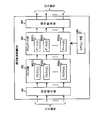
- FIG. 2 shows a configuration example of the signal transfer device 103 (2) directly connected to the distributed station device 104 (2).
- the signal transfer device 103 (2) will be described with reference to FIG. 2, the same applies to the signal transfer device 103 (1) and the signal transfer device 103 (3) that are directly connected to the distributed station device 104.
- the signal transfer device 103 (2) includes a signal distribution unit 201, a buffer unit 202, a time gate unit 203, a signal transfer unit 204, a scheduler unit 205, a calculation unit 206, a traffic counter unit 207, a disposal unit 208, and It has a linked IF 251.
- the signal distribution unit 201 has a function of distributing input signals to buffers according to priority. For example, the signal distribution unit 201 uses a frame received from the distributed station device 104 or another signal transfer device 103 in the upstream direction and a frame received from the central station device 102 or another signal transfer device 103 in the downstream direction as a frame header. It sorts based on the stored priority and outputs it to the buffer unit 202. In the present embodiment, the signal distribution unit 201 also inputs control information such as mobile scheduling information output from the other signal transfer device 103 and outputs the control information to the scheduler unit 205 or the like.
- control information such as mobile scheduling information output from the other signal transfer device 103 and outputs the control information to the scheduler unit 205 or the like.
- the buffer unit 202 is a buffer memory that temporarily holds high-priority frames or low-priority frames distributed by the signal distribution unit 201 according to their priorities.
- the buffer unit 202 has a plurality of preset buffers for each priority (for example, a high priority buffer, a low priority buffer, etc.).
- the buffer unit 202 has n buffers (n is a positive integer) of the buffer 202 (1), the buffer 202 (2), ..., The buffer 202 (n).
- the time gate unit 203 includes a plurality of gates corresponding to each of the plurality of buffers of the buffer unit 202, and opens and closes the gates in response to a command from the scheduler unit 205.
- the time gate portion 203 has n gates of gate 203 (1), gate 203 (2), ..., Gate 203 (n).
- the time gate unit 203 controls opening and closing of a gate that outputs frames from each buffer in which frames for each priority are held, for example, in response to a command from the scheduler unit 205.
- the signal transfer unit 204 has a function of transferring a frame output for each gate of the time gate unit 203 to a designated output destination based on a command of the signal transfer management device 101 described later.
- the scheduler unit 205 controls whether or not to transmit the signal held in each buffer of the buffer unit 202 by opening and closing each gate of the time gate unit 203 based on the preset scheduling information.
- the scheduling information is information on the gate start time, gate opening time, gate opening cycle, etc. of each gate of the time gate unit 203 for the frames held in each buffer according to the priority of the buffer unit 202. ..
- the scheduling information of the scheduler unit 205 is adjusted based on the calculation result of the calculation unit 206, and the scheduler unit 205 can open and close the gate of the low priority frame.
- the scheduler unit 205 When the scheduling information is not adjusted, the scheduler unit 205 periodically opens and closes the gate at a gate start time, a gate opening time, and a gate opening cycle predetermined for each priority. When the scheduling information is not adjusted, the gate is periodically opened and closed at a gate start time, a gate opening time, and a gate opening cycle predetermined for each priority.
- the information input from the distributed station apparatus 104 (2) via the cooperation IF 251 is referred to as mobile scheduling information
- the information used by the scheduler unit 205 is referred to as scheduling information.
- the calculation unit 206 uses the traffic amount for each priority that passes through the buffer unit 202 output by the traffic counter unit 207 and the mobile scheduling information input from the distributed station device 104 (2) via the cooperation IF 251 and the disposal unit 208. Based on this, the end of the high priority frame (completion of the high priority frame transmission section) is determined, and the opening / closing timing of the gate of the low priority frame is calculated.
- the mobile scheduling information includes information on the amount of data of high priority frames every 1 ms that will flow from the distributed station apparatus 104 (2) in the future.
- the calculation unit 206 compares the amount of data included in the mobile scheduling information with the traffic amount of the high priority frame measured by the traffic counter unit 207, and the traffic amount of the high priority frame measured by the traffic counter unit 207 is larger.
- the gate of the high-priority frame is closed for the scheduler unit 205 and another priority is given. Issue a command to open the gate in the frame of the degree.
- the calculation unit 206 does not immediately after the traffic amount measured by the traffic counter unit 207 becomes larger, but a predetermined fixed time elapses after the traffic amount becomes larger. The above command may be issued later.
- the traffic counter unit 207 counts the traffic amount of the buffer unit 202 according to the priority. Then, the traffic counter unit 207 transmits the traffic amount as monitor information to the signal transfer management device 101, and outputs the traffic amount to the calculation unit 206. Here, the traffic counter unit 207 clears the counter to zero at the beginning of the cycle in accordance with the cycle of the high priority frame transmitted from the distributed station apparatus 104 (2) based on the mobile scheduling information, and monitors the traffic amount.
- the discard unit 208 Based on the IF information transmission determination notification received from the signal transfer management device 101, the discard unit 208 receives a mobile scheduling information input from the distributed station device 104 (2) via the linked IF 251 when the IF information is instructed to be discarded. Discard. If the mobile scheduling information is not discarded, the discard unit 208 does not output the mobile scheduling information input from the distributed station device 104 (2) to the calculation unit 206, but passes through the mobile scheduling information as it is from the signal transfer unit 204 to the next stage and thereafter. Is output to the signal transfer device 103 (signal transfer device 103 (4) in the example of FIG. 1). In this case, the calculation unit 206 and the traffic counter unit 207 do not perform the operation as described with reference to FIG. 2, and the scheduler unit 205 controls the time gate unit 203 based on the preset scheduling information.
- the cooperation IF 251 is a dedicated interface with the distribution station device 104 (2), and the signal transfer device 103 (2) inputs mobile scheduling information from the distribution station device 104 (2) via the cooperation IF 251.
- the mobile scheduling information input from the distributed station apparatus 104 (2) is output to the calculation unit 206 via the disposal unit 208.
- the signal transfer device 103 (2) directly connected to the distributed station device 104 (2) is a high priority frame included in the mobile scheduling information input from the distributed station device 104 (2) via the cooperation IF 251.
- Bandwidth utilization efficiency can be improved by opening the gate of the low priority frame based on the amount of data of the above and the amount of traffic of the frame actually input from the distributed station apparatus 104 (2).
- the signal transfer device 103 (2) according to the present embodiment notifies the signal transfer management device 101 of the traffic amount of the input frame, and based on the necessity of transmitting the mobile scheduling information received from the signal transfer management device 101. Since it has a function of discarding mobile scheduling information, it is possible to reduce the transfer of unnecessary mobile scheduling information and effectively use the network bandwidth.
- the determination method of the signal transfer management device 101 will be described later.
- FIG. 3 shows a configuration example of the signal transfer device 103 (4) that is not directly connected to the distributed station device 104.
- the basic configuration of the signal transfer device 103 (4) is the same as that of the signal transfer device 103 described with reference to FIG.
- the example of the signal transfer device 103 (4) is shown in FIG. 3, among the signal transfer devices 103 connected in multiple stages, the signal transfer devices 103 of the next and subsequent stages that are not directly connected to the distributed station device 104 are used. The same is true in some cases.
- the signal distribution unit 201 outputs the mobile scheduling information input from the signal transfer device 103 (for example, the signal transfer device 103 (2)) in the previous stage to the discard unit 208.
- the disposal unit 208 discards the mobile scheduling information when the IF information is instructed to be discarded, and the mobile scheduling information when there is no disposal instruction. Is output to the calculation unit 206.
- the signal transfer device 103 (4) inputs the mobile scheduling information to the calculation unit 206, and the signal transfer device 103 (4) has the signal transfer device 103 of the next stage (in the example of FIG. 1, the signal).
- the mobile scheduling information is transferred from the signal transfer unit 204 to the signal transfer device 103 in the next stage.
- the calculation unit 206 has high priority based on the amount of data of the high priority frame included in the mobile scheduling information and the traffic amount of the high priority frame monitored by the traffic counter unit 207. After determining the end of the frame, the scheduler unit 205 can open the gate of the low priority frame.
- the discard unit 208 does not output the mobile scheduling information input from the signal transfer device 103 in the previous stage to the calculation unit 206, but passes through the mobile scheduling information as it is from the signal transfer unit 204 to the next stage and thereafter. Output to the signal transfer device 103.
- the calculation unit 206 and the traffic counter unit 207 do not perform the above-described operations, and the scheduler unit 205 controls the time gate unit 203 based on preset scheduling information.
- the traffic counter unit 207 monitors the traffic status in the buffer unit 202 and counts the traffic amount input to the buffer unit 202 according to the priority.
- the calculation unit 206 sets the traffic amount for each priority passing through the buffer unit 202 output by the traffic counter unit 207 and the signal transfer device 103 via the signal distribution unit 201.
- the end of the high priority frame is determined based on the mobile scheduling information input from (2). Specifically, the calculation unit 206 compares the amount of data included in the mobile scheduling information transferred from the signal transfer device 103 (2) in the previous stage with the traffic amount of the high priority frame measured by the traffic counter unit 207. When the traffic amount of the high priority frame measured by the traffic counter unit 207 becomes larger than the data amount of the high priority frame included in the mobile scheduling information (that is, when the transmission of the high priority frame is completed).
- the calculation unit 206 has a larger traffic amount, not immediately after the traffic amount measured by the traffic counter unit 207 has become larger.
- the above command may be issued after a predetermined fixed time has elapsed.
- the signal transfer device 103 (4) that is not directly connected to the distributed station device 104 has the data amount of the high priority frame included in the mobile scheduling information transferred from the signal transfer device 103 (2) in the previous stage and the data amount of the high priority frame.
- the band utilization efficiency can be improved by opening the gate of the low priority frame based on the traffic amount of the high priority frame actually input from the signal transfer device 103 (2).
- the signal transfer device 103 (4) notifies the signal transfer management device 101 of the traffic amount of the input frame and receives it from the signal transfer management device 101, similarly to the signal transfer device 103 (2) described with reference to FIG. Since it has a function of discarding the mobile scheduling information based on whether or not the mobile scheduling information needs to be transmitted, the transfer of unnecessary mobile scheduling information can be reduced and the network bandwidth can be effectively used.
- FIG. 2 and FIG. 3 an example of transferring mobile scheduling information from the signal transfer device 103 (2) to the signal transfer device 103 (4) has been described, but the signal transfer device 103 (4) and the central station device 102 If another signal transfer device 103 exists between the two, the mobile scheduling information is transferred from the signal transfer device 103 (4) to the signal transfer device 103 of the next stage, and the same process is performed by the signal transfer device 103 of the next stage. Will be executed.
- FIG. 4 shows a configuration example of the signal transfer management device 101 according to the present embodiment.
- the signal transfer management device 101 includes a transfer destination determination unit 301, a monitor unit 302, and an IF information transmission necessity determination unit 303.
- the transfer destination determination unit 301 confirms the requirements such as the required bandwidth and delay of the signal flow, compares it with the existing flow accommodation status, and determines a transfer route that satisfies the requirements. decide. Then, the transfer destination determination unit 301 notifies each signal transfer device 103 of the output destination port information of the signal flow so as to be the determined transfer path. Each signal transfer device 103 outputs the input signal flow to the designated output port according to the output destination port information received from the signal transfer management device 101.
- the monitor unit 302 receives the measurement result of the traffic amount from each signal transfer device 103, and notifies the IF information transmission necessity determination unit 303.
- the IF information transmission necessity determination unit 303 determines the necessity of transmitting IF information to each signal transfer device 103.
- the IF information is mobile scheduling information acquired from the linked IF 251.
- the IF information transmission necessity determination unit 303 gates based on the mobile scheduling information, for example, when the traffic volume of the low priority frame in a certain signal transfer device 103 is sufficiently small (for example, when it is less than a predetermined threshold value). Since it is considered unnecessary to extend the length (gate opening time), the signal transfer device outputs the mobile scheduling information to the calculation unit 206, or transmits the mobile scheduling information to the signal transfer device 103 in the previous stage. The unnecessary determination result is transmitted, and the transfer of unnecessary information to the signal transfer device 103 is stopped. As a result, the signal transfer device 103 or the next-stage signal transfer device 103 does not receive the mobile scheduling information, so that the gate opening / closing operation normally performed by the scheduler unit 205 is performed.
- the mobile scheduling information in the signal transfer device 103 when the traffic amount of the high priority frame is always large and almost all the reserved gate lengths are used, there is no possibility that the band can be released. Therefore, the mobile scheduling information in the signal transfer device 103. To the signal transfer device 103 in the previous stage or the output to the calculation unit 206 of the above, the determination result that the transmission of the mobile scheduling information is unnecessary is transmitted, and the transfer of the unnecessary information to the signal transfer device 103 is stopped. As a result, the signal transfer device 103 or the next-stage signal transfer device 103 does not receive the mobile scheduling information, so that the gate opening / closing operation normally performed by the scheduler unit 205 is performed.
- the signal transfer management device 101 monitors the traffic amount of each signal transfer device 103, determines whether or not mobile scheduling information needs to be transmitted to all the signal transfer devices 103, and opens and closes the gate. When there is no need to make adjustments and the transfer of mobile scheduling information is unnecessary, the network bandwidth can be effectively used by stopping the transfer of mobile scheduling information.
- the signal transfer management device 101 also instructs the scheduler unit 205 of each signal transfer device 103 of normal scheduling information, but unless the calculation unit 206 adjusts the opening and closing of the gate, the scheduler unit 205 is normal. The opening and closing of the gate is controlled based on the scheduling information.
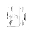
- FIG. 5 shows a configuration example of the signal transfer device 800 of the comparative example.
- the signal transfer device 800 includes a signal distribution unit 801, a buffer unit 802, a time gate unit 803, a signal transfer unit 804, and a scheduler unit 805.
- the signal transfer device 800 has a TAS function and controls the opening and closing of the gate according to the priority.
- the signal distribution unit 801 has a function of distributing input signals to buffers according to priority, similarly to the signal distribution unit 201 according to the present embodiment.
- the buffer unit 802 is a buffer memory that temporarily holds high-priority frames or low-priority frames distributed by the signal distribution unit 801 according to their priorities.
- the buffer unit 802 has n buffers of the buffer 802 (1), the buffer 802 (2), ..., The buffer 802 (n).
- the time gate unit 803 includes a plurality of gates corresponding to each of the plurality of buffers of the buffer unit 802, and opens and closes the gates in response to a command from the scheduler unit 805.
- the time gate unit 803 has n gates of gate 803 (1), gate 803 (2), ..., Gate 803 (n).
- the signal transfer unit 804 has a function of transferring a frame output from the time gate unit 803 for each gate to a designated output destination from the signal transfer management device 101.
- the scheduler unit 805 periodically opens and closes the gate at the gate start time, the gate opening time, and the gate opening cycle according to the priority based on the scheduling information determined in advance, and preferentially transfers the high priority frame.
- the signal transfer device 800 reserves a time slot for the high priority frame by the TAS function, opens the gate in the reserved time slot to transfer the high priority frame, and transfers another priority frame. By closing the gate of, high priority frames can be transferred preferentially.
- the reserved gate length gate opening time
- the gate is occupied even when the traffic amount of the high priority frame is small.
- frames of other priorities are not transferred, there is a problem that the utilization efficiency of the network bandwidth is lowered.
- the signal transfer device 103 includes the amount of data of the high priority frame included in the mobile scheduling information input from the distributed station device 104 via the cooperation IF 251 and the data amount actually input from the distributed station device 104.
- the signal transfer management device 101 monitors the traffic amount of each signal transfer device 103, determines whether or not mobile scheduling information needs to be transmitted to all the signal transfer devices 103, and adjusts the opening and closing of the gate. When it is not necessary to transfer the mobile scheduling information and the transfer of the mobile scheduling information is unnecessary, the network bandwidth can be effectively used by stopping the transfer of the mobile scheduling information.
- the distributed station device 104 is a wireless device and the central station device 102 is a wireless control device, and the wireless device and the wireless control device share and execute the functions of one base station. If there is a difference in the way of sharing, and if the MAC layer that is considered to output mobile scheduling information exists on the wireless device side, it can be realized with the same configuration as in FIG. If the MAC layer that is considered to output the mobile scheduling information exists on the wireless control device side, the cooperation IF for receiving the mobile scheduling information between the central station device 102 and the signal transfer device 103 (4). Is required.
- the signal transfer device 103 (4) is connected to the signal transfer device 103 (1) by the distributed station device 104 ( 1) Mobile scheduling information, signal transfer device 103 (2) transfers mobile scheduling information of distributed station device 104 (2), and signal transfer device 103 (3) transfers mobile scheduling information of distributed station device 104 (3). do.
- the signal transfer management device 101 does not need to receive the monitor information of the traffic counter unit 207, and the scheduler unit 205 does not need to receive the monitor information. It is possible to issue an instruction that does not close the gate of the low priority frame.
- the signal transfer system, the signal transfer device, the signal transfer management device, the signal transfer method, and the signal transfer program according to the present invention are low based on the mobile scheduling information received from the distributed station device.
- the band utilization efficiency is improved, and the transfer of the mobile scheduling information is stopped when it is determined that the transfer of the mobile scheduling information is unnecessary based on the traffic amount measured by each signal transfer device. Therefore, the network bandwidth can be used effectively.
- the device having each block shown in FIGS. 2, 3 and 4 has been described, but it can also be realized by a computer that executes a program of a signal transfer method corresponding to the processing performed by each block.
- the program may be recorded on a recording medium and provided, or may be provided through a network.
Landscapes
- Engineering & Computer Science (AREA)
- Computer Networks & Wireless Communication (AREA)
- Signal Processing (AREA)
- Data Exchanges In Wide-Area Networks (AREA)
- Mobile Radio Communication Systems (AREA)
Abstract
分散局装置と中央局装置との間のネットワークを構成する多段接続された複数の信号転送装置と、信号転送管理装置とを有する信号転送システムにおいて、分散局装置に直接接続される第1の信号転送装置は、分散局装置から次に出力される高優先の信号のデータ量を取得するとともに、分散局装置から受信する信号のトラヒック量を計測して信号転送管理装置に送信し、信号転送管理装置からトラヒック量に基づいて分散局装置から取得したデータ量を廃棄するか否かの判定結果を受信し、判定結果によりデータ量を廃棄しない場合、データ量と計測された高優先の信号のトラヒック量とに基づいて、低優先の信号を転送するゲートの開閉タイミングを計算して、計算の結果に基づいて、低優先の信号を転送するゲートを開閉する。これにより、ネットワーク帯域の有効利用が可能になる。
Description
本発明は、TAS(Time Aware Shaper)機能を利用する信号転送技術に関する。
セルラーシステムを構成するネットワークには、モバイルフロントホール(MFH:Mobile Fronthaul)やモバイルバックホール(MBH:Mobile Backhaul)等がある。MBHは、基地局に相当する分散局装置と、分散局装置を制御する集約局間のネットワークである。一方、MFHは、基地局の構成を無線制御装置と無線装置に分離して配置する構成とした場合の無線制御装置-無線装置の区間に対応する。この区間は従来、ポイント・ツー・ポイント接続が用いられてきたが、レイヤ2スイッチを多段に接続した構成でネットワーク化することも検討されており(非特許文献1参照)、ポイント・ツー・ポイント接続と比べて効率的な収容が実現される。これらネットワークでは、厳しい遅延要件を満たす必要があり、高優先の信号の遅延を小さくするために、信号転送装置へのTAS機能搭載が提案されている。
以降の本発明に関して、MBHを例に挙げて説明を進めるが、分散局装置を無線装置、中央局装置を無線制御装置と読み替えれば、MFHにも適用することができる。
"Time-Sensitive Networking for Fronthaul",IEEE Std P802.1CM,May 7,2018
TASでは、高優先の信号に対してタイムスロットを予約し、予約されたタイムスロットでゲートを開いて信号を転送するとともに、他の優先度の信号のゲートを閉じることにより高優先の信号が優先的に転送される。しかし、従来のTASでは、高優先の信号のトラヒック量に依らず予約するゲート長が一定のため、高優先の信号のトラヒック量が少ない場合でも他の優先度の信号の転送が行われず、ネットワークの帯域利用効率が低下するという課題がある。
そこで、分散局装置から受信するモバイルスケジューリング情報に基づいて、必要な期間のみ高優先の信号のゲートを開くことにより、帯域利用効率を改善する技術が考えられるが、この場合、モバイルスケジューリング情報は、1ms程度の間隔のPUCCH(Physical Uplink Control Channel)信号により高頻度で送信されるため、多段の信号転送装置を介して上位側の信号転送装置にフレームを転送するMBHのネットワークの場合、ネットワーク内の帯域が圧迫されてしまうという問題がある。
本発明は、分散局装置から受信するモバイルスケジューリング情報に基づいて、必要な期間のみ高優先の信号のゲートを開閉する制御が不要の場合はモバイルスケジューリング情報の転送を止めることにより、ネットワーク帯域を有効に利用することができる信号転送システム、信号転送装置、信号転送管理装置、信号転送方法および信号転送プログラムを提供することを目的とする。
本発明は、無線基地局装置に対応する分散局装置と、前記無線基地局装置を集中制御する中央局装置と、前記分散局装置と前記中央局装置との間のネットワークを構成する多段接続された複数の信号転送装置と、複数の前記信号転送装置を制御する信号転送管理装置とを有する信号転送システムにおいて、複数の前記信号転送装置のうち、前記分散局装置に直接接続される第1の信号転送装置は、前記分散局装置から次に出力される高優先の信号のデータ量を取得するとともに、前記分散局装置から受信する信号のトラヒック量を計測して前記信号転送管理装置に送信し、前記信号転送管理装置から前記データ量を廃棄するか否かの判定結果を受信し、前記判定結果により前記データ量を廃棄しない場合、前記データ量と前記計測された前記高優先の信号のトラヒック量とに基づいて、低優先の信号を転送するゲートの開閉タイミングを計算して、前記計算の結果に基づいて、前記低優先の信号を転送するゲートを開閉することを特徴とする。
また、本発明は、無線基地局装置に対応する分散局装置と、前記無線基地局装置を集中制御する中央局装置と、前記分散局装置と前記中央局装置との間のネットワークを構成する信号転送装置において、前記分散局装置に直接接続される場合、前記分散局装置から次に出力される高優先の信号のデータ量を取得する連携インターフェースと、前記分散局装置から受信する信号のトラヒック量を計測するとともに、前記トラヒック量を信号転送管理装置に送信するカウンタ部と、前記データ量と前記計測された前記高優先の信号のトラヒック量とに基づいて、低優先の信号を転送するゲートの開閉タイミングを計算する計算部と、前記信号転送管理装置から前記データ量を廃棄するか否かの判定結果を受信し、前記判定結果により前記データ量を廃棄しない場合、前記データ量を前記計算部に出力する廃棄部と、前記計算部の計算結果に基づいて、前記低優先の信号を転送するゲートを開閉するスケジューラ部とを有することを特徴とする。
また、本発明は、無線基地局装置に対応する分散局装置と、前記無線基地局装置を集中制御する中央局装置と、前記分散局装置と前記中央局装置との間のネットワークを構成する多段接続された複数の信号転送装置を制御する信号転送管理装置において、前記信号転送装置が前記分散局装置から受信する信号のトラヒック量の計測結果を受信するモニタ部と、前記モニタ部が前記信号転送装置から受信する前記トラヒック量に基づいて、前記信号転送装置が前記分散局装置から取得したデータ量を廃棄するか否かの判定を行い、判定結果を前記信号転送装置に送信する判定部とを有することを特徴とする。
また、本発明は、無線基地局装置に対応する分散局装置と、前記無線基地局装置を集中制御する中央局装置と、前記分散局装置と前記中央局装置との間のネットワークを構成する多段接続された複数の信号転送装置と、複数の前記信号転送装置を制御する信号転送管理装置とを有する信号転送システムにおける信号転送方法であって、複数の前記信号転送装置のうち、前記分散局装置に直接接続される第1の信号転送装置は、前記分散局装置から次に出力される高優先の信号のデータ量を取得する処理と、前記分散局装置から受信する信号のトラヒック量を計測して、前記信号転送管理装置に送信する処理と、前記信号転送管理装置から前記データ量を廃棄するか否かの判定結果を受信し、前記判定結果に基づいて、前記データ量を廃棄しない場合は当該データ量を出力し、前記データ量を廃棄する場合は当該データ量を廃棄する処理と、前記データ量を廃棄しない場合、前記データ量と前記計測された前記高優先の信号のトラヒック量とに基づいて、低優先の信号を転送するゲートの開閉タイミングを計算する処理と、前記計算の結果に基づいて、前記低優先の信号を転送するゲートを開閉する処理とを行うことを特徴とする。
また、本発明に係る信号転送プログラムは、前記信号転送方法で行う処理をコンピュータに実行させることを特徴とする。
本発明に係る信号転送システム、信号転送装置、信号転送管理装置、信号転送方法および信号転送プログラムは、分散局装置から受信するモバイルスケジューリング情報に基づいて、低優先の信号のゲートを開閉する制御が不要の場合はモバイルスケジューリング情報の転送を止めることにより、ネットワーク帯域を有効に利用することができる。
以下、図面を参照して本発明に係る信号転送システム、信号転送装置、信号転送管理装置、信号転送方法および信号転送プログラムの実施形態について説明する。なお、以降の実施形態で説明する信号転送装置は、L2SW(Layer 2 SWitch)などのネットワーク機器に対応し、信号転送管理装置は、信号転送装置の動作を管理および制御する。
図1は、本実施形態に係る信号転送システム100の構成例を示す。図1において、信号転送システム100は、信号転送管理装置101、中央局装置102、信号転送装置103(1)、信号転送装置103(2)、信号転送装置103(3)、信号転送装置103(4)、分散局装置104(1)、分散局装置104(2)および分散局装置104(3)を有する。ここで、以降の説明において、信号転送装置103(1)から信号転送装置103(4)に共通の説明を行う場合は、符号末尾の(番号)を省略して、信号転送装置103と記載する。分散局装置104(1)から分散局装置104(3)についても同様に記載する。
図1に示す信号転送システム100は、複数の分散局装置104と中央局装置102とに分離して配置される無線基地局装置において、多段接続される複数の信号転送装置103により、分散局装置104と中央局装置102との間のMBHのネットワークを構成する。
図1において、分散局装置104(1)、分散局装置104(2)および分散局装置104(3)は、それぞれ無線端末(例えば、携帯端末、IoT端末等)と無線通信し、通信信号の高優先フレームは、信号転送装置103(1)から信号転送装置103(4)で構成されるMBHのネットワークを介して、中央局装置102に集約される。
中央局装置102は、複数の分散局装置104からの上り方向の信号をMBHのネットワークを介して集約するとともに、各分散局装置104への下り方向の信号をMBHのネットワークを介して分配する。
信号転送装置103は、分散局装置104と中央局装置102との間で信号を転送する装置であり、MBHのネットワークを構成する。なお、図1のネットワークは、スター型のネットワークを示しているが、リング型、メッシュ型等のネットワークであっても本実施形態は同様に適用可能である。
ここで、以降の説明において、多段接続される複数の信号転送装置103に対して、分散局装置104に近い側を下位側、中央局装置102に近い側を上位側と称する。また、信号の流れる方向に対して、信号を送信する側を前段、信号を受信する側を次段と称する。例えば図1の場合、分散局装置104から中央局装置102への上り方向に対して、信号転送装置103(1)、信号転送装置103(2)および信号転送装置103(3)は、下位側の信号転送装置103であり、信号転送装置103(4)に対して前段の信号転送装置103である。同様に、信号転送装置103(4)は上位側の信号転送装置103であり、信号転送装置103(1)、信号転送装置103(2)および信号転送装置103(3)に対して次段の信号転送装置103である。
図1の例では、分散局装置104(1)、分散局装置104(2)および分散局装置104(3)にそれぞれ接続される下位側の信号転送装置103(1)、信号転送装置103(2)および信号転送装置103(3)と、信号転送装置103(1)から信号転送装置103(3)の信号を集約して中央局装置102に接続する上位側の信号転送装置103(4)とを有する。また、信号転送装置103(1)、信号転送装置103(2)および信号転送装置103(3)は、分散局装置104(1)、分散局装置104(2)および分散局装置104(3)にそれぞれ専用の連携インターフェース(連携IF251)により接続され、分散局装置104からPUCCH信号によるモバイルスケジューリング情報を取得する。ここで、モバイルスケジューリング情報には、分散局装置104から今後送信されるフレームの送信タイミングやデータ量などに関する情報が含まれている。なお、分散局装置104に連携IF251で直接接続される信号転送装置103(1)、信号転送装置103(2)および信号転送装置103(3)は、第1の信号転送装置に対応し、分散局装置104に連携IF251で直接接続されない信号転送装置103(4)は、第2の信号転送装置に対応する。
本実施形態に係る信号転送装置103は、分散局装置104から連携IF251を介して入力するモバイルスケジューリング情報に含まれる高優先フレームのデータ量と、実際に分散局装置104から入力するフレームのトラヒック量とに基づいて、低優先フレームのゲートを開閉するタイミング(開閉タイミング)を計算し、必要な期間のみ低優先フレームのゲートを開く機能を有する。ここで、ゲートは、開いた状態で信号を通過させ、閉じた状態で信号を遮断する。
特に、本実施形態に係る信号転送装置103は、入力するフレームのトラヒック量をモニタして信号転送管理装置101に通知し、信号転送管理装置101から受け取るモバイルスケジューリング情報の送信要否に基づいて、モバイルスケジューリング情報を廃棄する機能を有する。
図1において、信号転送管理装置101は、信号転送装置103が構成するネットワークにおいて、分散局装置104と中央局装置102との間の信号を通す経路を決定して、各信号転送装置103に指示したり、各信号転送装置103のスケジューラ部205への指示を行う。特に、本実施形態に係る信号転送管理装置101は、各信号転送装置103が計測するトラヒック量に基づいて、モバイルスケジューリング情報の転送が不要と判定した場合はモバイルスケジューリング情報の転送を止めるように制御する。
ここで、分散局装置104と中央局装置102との間で通信される信号は低遅延が求められるため、信号転送装置103はTAS機能を搭載している。なお、以降の説明において、分散局装置104と中央局装置102との間で通信する信号を具体的に示す場合はフレームと称するが、基本的に信号とフレームは同じものを示す。
TASは、従来技術で述べたように、優先度の高いトラヒックのフレーム(高優先フレーム)に対してタイムスロットを予約し、予約されたタイムスロットでゲートを開いて高優先フレームを転送するとともに、他の優先度のフレームのゲートを閉じることにより高優先フレームが優先的に転送される。しかし、従来のTASでは、高優先フレームのトラヒック量に依らず予約するゲート長が一定のため、高優先フレームのトラヒック量が少ない場合でもゲートを占有してしまい、他の優先度のフレームの転送が行われないので、ネットワーク帯域の利用効率が低下するという問題があった。
そこで、本実施形態に係る信号転送システム100では、分散局装置104から出力されるモバイルスケジューリング情報により高優先フレームのデータ量を取得して、データ量に応じて高優先フレームの終わり(高優先フレーム送信区間の完了)を判定し、ゲートを他の優先度のフレームに開放する機能を有する。これにより、本実施形態に係る信号転送システム100は、高優先フレームのトラヒック量が少ない場合でもゲートを占有することなく他の優先度のトラヒックの転送が可能となり、ネットワーク帯域の利用効率の低下を防ぐことができる。
このように、本実施形態に係る信号転送システム100は、連携IF251を介して分散局装置104から入力するモバイルスケジューリング情報に基づいて、ゲート開閉のタイミングを制御することにより、ネットワーク帯域の有効利用を図ることができる。特に、本実施形態に係る信号転送管理装置101は、各信号転送装置103のトラヒック量をモニタして全ての信号転送装置103へのモバイルスケジューリング情報の送信要否を判定して、送信不要の場合はモバイルスケジューリング情報を廃棄するので、不要なモバイルスケジューリング情報の転送を削減し、ネットワーク帯域の有効利用を図ることができる。
図2は、分散局装置104(2)に直接接続されている信号転送装置103(2)の構成例を示す。なお、図2では、信号転送装置103(2)について説明するが、分散局装置104に直接接続される信号転送装置103(1)および信号転送装置103(3)についても同様である。
図2において、信号転送装置103(2)は、信号振分部201、バッファ部202、タイムゲート部203、信号転送部204、スケジューラ部205、計算部206、トラヒックカウンタ部207、廃棄部208および連携IF251を有する。
信号振分部201は、入力信号を優先度別のバッファに振り分ける機能を有する。例えば、信号振分部201は、上り方向の場合は分散局装置104または他の信号転送装置103、下り方向の場合は中央局装置102または他の信号転送装置103から受信するフレームをフレームヘッダに格納された優先度に基づいて振り分け、バッファ部202に出力する。なお、本実施形態では、信号振分部201は、他の信号転送装置103から出力されるモバイルスケジューリング情報などの制御情報も入力してスケジューラ部205などへ出力する。
バッファ部202は、信号振分部201により振り分けられた高優先のフレームまたは低優先のフレームを優先度別に一時的に保持するバッファメモリである。なお、バッファ部202は、予め設定された優先度別の複数のバッファ(例えば高優先のバッファ、低優先のバッファなど)を有する。図2の例では、バッファ部202は、バッファ202(1)、バッファ202(2)、・・・、バッファ202(n)のn個(nは正の整数)のバッファを有する。
タイムゲート部203は、バッファ部202の複数のバッファ毎に対応する複数のゲートを備え、スケジューラ部205の指令に応じてゲートの開閉を行う。図2の例では、タイムゲート部203は、ゲート203(1)、ゲート203(2)、・・・、ゲート203(n)のn個のゲートを有する。タイムゲート部203は、例えばスケジューラ部205の指令に応じて、優先度別のフレームが保持された各バッファからフレームを出力するゲートの開閉を制御する。
信号転送部204は、後述する信号転送管理装置101の指令に基づいて、タイムゲート部203のゲート毎に出力されるフレームを指定された出力先に転送する機能を有する。
スケジューラ部205は、予め設定されたスケジューリング情報に基づいて、タイムゲート部203の各ゲートの開閉を行うことによりバッファ部202の各バッファに保持されている信号を送信するか否かを制御する。ここで、スケジューリング情報は、バッファ部202の優先度別の各バッファに保持されたフレームに対して、タイムゲート部203の各ゲートのゲート開始時間、ゲート開放時間、ゲート開放周期などに関する情報である。本実施形態では、計算部206の計算結果に基づいて、スケジューラ部205のスケジューリング情報が調整され、スケジューラ部205は、低優先フレームのゲートを開閉することができる。なお、スケジューラ部205は、スケジューリング情報の調整が行われない場合、優先度別に予め決められたゲート開始時間、ゲート開放時間、ゲート開放周期で周期的にゲートを開閉している。スケジューリング情報の調整が行われない場合は、優先度別に予め決められたゲート開始時間、ゲート開放時間、ゲート開放周期で周期的にゲートを開閉している。ここで、本実施形態では、分散局装置104(2)から連携IF251を介して入力する情報をモバイルスケジューリング情報、スケジューラ部205が使用する情報をスケジューリング情報と称する。
計算部206は、トラヒックカウンタ部207が出力するバッファ部202を通過する優先度別のトラヒック量と、連携IF251および廃棄部208を介して分散局装置104(2)から入力するモバイルスケジューリング情報とに基づいて、高優先フレームの終わり(高優先フレーム送信区間の完了)を判定し、低優先フレームのゲートの開閉タイミングを計算する。ここで、モバイルスケジューリング情報には、分散局装置104(2)から今後流れてくる1ms置きの高優先フレームのデータ量の情報が含まれている。計算部206は、モバイルスケジューリング情報に含まれるデータ量と、トラヒックカウンタ部207で計測する高優先フレームのトラヒック量とを比較して、トラヒックカウンタ部207で計測する高優先フレームのトラヒック量の方がモバイルスケジューリング情報に含まれる高優先フレームのデータ量よりも大きくなった場合(つまり、高優先フレームの送信が終了した場合)に、スケジューラ部205に対して高優先フレームのゲートを閉じて他の優先度のフレームにゲートを開放する命令を出す。なお、多少の誤差に対応するため、計算部206は、トラヒックカウンタ部207で計測するトラヒック量の方が大きくなった直後ではなく、トラヒック量の方が大きくなってから予め決められた一定時間経過後に上記の命令を出すようにしてもよい。
トラヒックカウンタ部207は、バッファ部202のトラヒック量を優先度別にカウントする。そして、トラヒックカウンタ部207は、トラヒック量をモニタ情報として信号転送管理装置101に送信するとともに、計算部206に出力する。ここで、トラヒックカウンタ部207は、モバイルスケジューリング情報に基づいて分散局装置104(2)から送信される高優先フレームの周期に合わせて、周期の先頭でカウンタをゼロクリアし、トラヒック量をモニタする。
廃棄部208は、信号転送管理装置101から受け取るIF情報送信判定通知に基づいて、IF情報の廃棄指示があった場合は、連携IF251を介して分散局装置104(2)から入力するモバイルスケジューリング情報を廃棄する。なお、廃棄部208は、モバイルスケジューリング情報を廃棄しない場合、分散局装置104(2)から入力するモバイルスケジューリング情報を計算部206に出力せずに、そのままスルーして信号転送部204から次段以降の信号転送装置103(図1の例では信号転送装置103(4))に出力する。この場合、計算部206およびトラヒックカウンタ部207は、図2で説明したような動作を行わず、スケジューラ部205は、予め設定されたスケジューリング情報に基づいてタイムゲート部203を制御する。
連携IF251は、分散局装置104(2)との間の専用のインターフェースで、信号転送装置103(2)は、連携IF251を介して分散局装置104(2)からモバイルスケジューリング情報を入力する。本実施形態では、分散局装置104(2)から入力するモバイルスケジューリング情報は、廃棄部208を介して計算部206に出力される。
このように、分散局装置104(2)に直接接続されている信号転送装置103(2)は、分散局装置104(2)から連携IF251を介して入力するモバイルスケジューリング情報に含まれる高優先フレームのデータ量と、実際に分散局装置104(2)から入力するフレームのトラヒック量とに基づいて、低優先フレームのゲートを開くことにより、帯域利用効率を改善することができる。特に、本実施形態に係る信号転送装置103(2)は、入力するフレームのトラヒック量を信号転送管理装置101に通知し、信号転送管理装置101から受け取るモバイルスケジューリング情報の送信要否に基づいて、モバイルスケジューリング情報を廃棄する機能を有するので、不要なモバイルスケジューリング情報の転送が削減され、ネットワーク帯域の有効利用を図ることができる。なお、信号転送管理装置101の判定方法については後述する。
図3は、分散局装置104に直接接続されていない信号転送装置103(4)の構成例を示す。図3において、信号転送装置103(4)の基本的な構成は、図2で説明した信号転送装置103と同じである。なお、図3では、信号転送装置103(4)の例を示したが、多段接続された信号転送装置103のうち、分散局装置104に直接接続されていない次段以降の信号転送装置103がある場合も同様である。
信号転送装置103(4)において、信号振分部201は、前段の信号転送装置103(例えば信号転送装置103(2))から入力するモバイルスケジューリング情報を廃棄部208に出力する。廃棄部208は、信号転送管理装置101から受け取るIF情報送信判定通知に基づいて、IF情報の廃棄指示があった場合は、モバイルスケジューリング情報を廃棄し、廃棄指示がなかった場合は、モバイルスケジューリング情報を計算部206に出力する。ここで、信号転送装置103(4)は、モバイルスケジューリング情報を計算部206に入力するとともに、信号転送装置103(4)に次段の信号転送装置103がある場合(図1の例において、信号転送装置103(4)と中央局装置102との間に他の信号転送装置103がある場合)は、信号転送部204から次段の信号転送装置103にモバイルスケジューリング情報を転送する。ここで、計算部206は、図2で説明したように、モバイルスケジューリング情報に含まれる高優先フレームのデータ量と、トラヒックカウンタ部207がモニタする高優先フレームのトラヒック量とに基づいて、高優先フレームの終わりを判定し、スケジューラ部205は、低優先フレームのゲートを開くことができる。
なお、廃棄部208は、モバイルスケジューリング情報を廃棄しない場合、前段の信号転送装置103から入力するモバイルスケジューリング情報を計算部206に出力せずに、そのままスルーして信号転送部204から次段以降の信号転送装置103に出力する。この場合、計算部206およびトラヒックカウンタ部207は、上述の動作を行わず、スケジューラ部205は、予め設定されたスケジューリング情報に基づいてタイムゲート部203を制御する。
図3において、トラヒックカウンタ部207は、図2で説明したように、バッファ部202内のトラヒック状況をモニタし、バッファ部202に入力されるトラヒック量を優先度別にカウントする。
計算部206は、廃棄部208がモバイルスケジューリング情報を廃棄しない場合、トラヒックカウンタ部207が出力するバッファ部202を通過する優先度別のトラヒック量と、信号振分部201を介して信号転送装置103(2)から入力するモバイルスケジューリング情報とに基づいて、高優先フレームの終わりを判定する。具体的には、計算部206は、前段の信号転送装置103(2)から転送されるモバイルスケジューリング情報に含まれるデータ量と、トラヒックカウンタ部207で計測する高優先フレームのトラヒック量とを比較して、トラヒックカウンタ部207で計測する高優先フレームのトラヒック量の方がモバイルスケジューリング情報に含まれる高優先フレームのデータ量よりも大きくなった場合(つまり、高優先フレームの送信が終了した場合)に、スケジューラ部205に対して高優先フレームのゲートを閉じて他の優先度のフレームにゲートを開放する命令を出す。なお、図2で説明したように、多少の誤差に対応するため、計算部206は、トラヒックカウンタ部207で計測するトラヒック量の方が大きくなった直後ではなく、トラヒック量の方が大きくなってから予め決められた一定時間経過後に上記の命令を出すようにしてもよい。
このように、分散局装置104に直接接続されていない信号転送装置103(4)は、前段の信号転送装置103(2)から転送されるモバイルスケジューリング情報に含まれる高優先フレームのデータ量と、実際に信号転送装置103(2)から入力する高優先フレームのトラヒック量とに基づいて、低優先フレームのゲートを開くことにより、帯域利用効率を改善することができる。特に、信号転送装置103(4)は、図2で説明した信号転送装置103(2)と同様に、入力するフレームのトラヒック量を信号転送管理装置101に通知し、信号転送管理装置101から受け取るモバイルスケジューリング情報の送信要否に基づいて、モバイルスケジューリング情報を廃棄する機能を有するので、不要なモバイルスケジューリング情報の転送が削減され、ネットワーク帯域の有効利用を図ることができる。
なお、図2および図3では、信号転送装置103(2)から信号転送装置103(4)にモバイルスケジューリング情報を転送する例を説明したが、信号転送装置103(4)と中央局装置102との間に他の信号転送装置103が存在する場合は、信号転送装置103(4)から次段の信号転送装置103にモバイルスケジューリング情報を転送し、次段の信号転送装置103で同様の処理が実行される。
[信号転送管理装置101]
図4は、本実施形態に係る信号転送管理装置101の構成例を示す。図4において、信号転送管理装置101は、転送先決定部301、モニタ部302およびIF情報送信要否判定部303を有する。
図4は、本実施形態に係る信号転送管理装置101の構成例を示す。図4において、信号転送管理装置101は、転送先決定部301、モニタ部302およびIF情報送信要否判定部303を有する。
転送先決定部301は、新規に追加したい信号フローが発生した場合、当該信号フローの所要帯域・遅延等の要件を確認して、既存のフロー収容状況と照らし合わせて、要件を満たす転送経路を決定する。そして、転送先決定部301は、決定した転送経路になるように、各信号転送装置103に対して、当該信号フローの出力先ポート情報を通知する。なお、各信号転送装置103は、信号転送管理装置101から受け取った出力先ポート情報に従って、入力される信号フローを指定された出力ポートに出力する。
モニタ部302は、各信号転送装置103からトラヒック量の計測結果を受信し、IF情報送信要否判定部303に通知する。
IF情報送信要否判定部303は、各々の信号転送装置103へのIF情報の送信要否を判定する。ここで、IF情報は、連携IF251から取得するモバイルスケジューリング情報である。IF情報送信要否判定部303は、例えば、ある信号転送装置103において低優先フレームのトラフィック量が十分に少ない場合(例えば予め決められた閾値未満の場合)には、モバイルスケジューリング情報に基づいてゲート長(ゲート開放時間)を拡張する必要が無いと考えられるので、当該信号転送装置においてモバイルスケジューリング情報の計算部206への出力、または、前段の信号転送装置103に対して、モバイルスケジューリング情報の送信不要の判定結果を送信し、信号転送装置103に対する不要な情報の転送を止める。これにより、当該信号転送装置103または次段の信号転送装置103は、モバイルスケジューリング情報を受け取らないため、通常スケジューラ部205が行うゲート開閉の動作を実施する。
あるいは、ある信号転送装置103において、高優先フレームのトラヒック量が常に大きく、予約したゲート長をほぼ全て使用している場合は、帯域を解放できる見込みが無いため、当該信号転送装置においてモバイルスケジューリング情報の計算部206への出力、または、前段の信号転送装置103に対して、モバイルスケジューリング情報の送信不要の判定結果を送信し、信号転送装置103に対する不要な情報の転送を止める。これにより、当該信号転送装置103または次段の信号転送装置103は、モバイルスケジューリング情報を受け取らないため、通常スケジューラ部205が行うゲート開閉の動作を実施する。
このように、本実施形態に係る信号転送管理装置101は、各信号転送装置103のトラヒック量をモニタして全ての信号転送装置103へのモバイルスケジューリング情報の送信要否を判定し、ゲート開閉の調整を行う必要が無くモバイルスケジューリング情報の転送が不要の場合はモバイルスケジューリング情報の転送を止めることにより、ネットワーク帯域を有効に利用することができる。なお、信号転送管理装置101は、各信号転送装置103のスケジューラ部205に通常のスケジューリング情報の指示も行うが、計算部206によるゲート開閉の調整が行われない限り、スケジューラ部205は、通常のスケジューリング情報に基づいてゲートの開閉を制御している。
[比較例]
図5は、比較例の信号転送装置800の構成例を示す。図5において、信号転送装置800は、信号振分部801、バッファ部802、タイムゲート部803、信号転送部804およびスケジューラ部805を有する。なお、信号転送装置800は、TAS機能を有し、優先度別にゲートを開閉する制御を行う。
図5は、比較例の信号転送装置800の構成例を示す。図5において、信号転送装置800は、信号振分部801、バッファ部802、タイムゲート部803、信号転送部804およびスケジューラ部805を有する。なお、信号転送装置800は、TAS機能を有し、優先度別にゲートを開閉する制御を行う。
信号振分部801は、本実施形態に係る信号振分部201と同様に、入力信号を優先度別のバッファに振り分ける機能を有する。
バッファ部802は、本実施形態に係るバッファ部202と同様に、信号振分部801により振り分けられた高優先のフレームまたは低優先のフレームを優先度別に一時的に保持するバッファメモリである。図5の例では、バッファ部802は、バッファ802(1)、バッファ802(2)、・・・、バッファ802(n)のn個のバッファを有する。
タイムゲート部803は、本実施形態に係るタイムゲート部203と同様に、バッファ部802の複数のバッファ毎に対応する複数のゲートを備え、スケジューラ部805の指令に応じてゲートの開閉を行う。図5の例では、タイムゲート部803は、ゲート803(1)、ゲート803(2)、・・・、ゲート803(n)のn個のゲートを有する。
信号転送部804は、タイムゲート部803からゲート毎に出力されるフレームを信号転送管理装置101から指定された出力先に転送する機能を有する。
スケジューラ部805は、予め決められたスケジューリング情報に基づいて、優先度別にゲート開始時間、ゲート開放時間、ゲート開放周期で周期的にゲートを開閉し、高優先フレームを優先的に転送する。
このように、信号転送装置800は、TAS機能により、高優先フレームに対してタイムスロットを予約し、予約されたタイムスロットでゲートを開いて高優先フレームを転送するとともに、他の優先度のフレームのゲートを閉じることにより高優先フレームを優先的に転送することができる。しかし、比較例の信号転送装置800は、高優先フレームのトラヒック量に依らず予約するゲート長(ゲート開放時間)が一定のため、高優先フレームのトラヒック量が少ない場合でもゲートを占有してしまい、他の優先度のフレームの転送が行われないので、ネットワーク帯域の利用効率が低下するという問題がある。
これに対して、本実施形態に係る信号転送装置103は、分散局装置104から連携IF251を介して入力するモバイルスケジューリング情報に含まれる高優先フレームのデータ量と、実際に分散局装置104から入力する高優先フレームのトラヒック量とに基づいて、低優先フレームのゲートを開くことにより、他の優先度のフレームの転送を行うことができるので、帯域利用効率を改善することができる。特に、本実施形態では、信号転送管理装置101は、各信号転送装置103のトラヒック量をモニタして全ての信号転送装置103へのモバイルスケジューリング情報の送信要否を判定し、ゲート開閉の調整を行う必要が無くモバイルスケジューリング情報の転送が不要の場合はモバイルスケジューリング情報の転送を止めることにより、ネットワーク帯域を有効に利用することができる。
なお、上述の実施形態ではMBHへの適用を前提に説明したが、MFHにも適用できる。MFHの場合には、分散局装置104が無線装置、中央局装置102が無線制御装置となり、無線装置と無線制御装置は、一つの基地局の機能をそれぞれ分担して実行している。その分担の仕方で差が生じ、もしモバイルスケジューリング情報を出力すると考えられるMACレイヤが無線装置側に存在する場合には、図1と同じ構成で実現できる。もしモバイルスケジューリング情報を出力すると考えられるMACレイヤが無線制御装置側に存在する分担の場合は、中央局装置102と信号転送装置103(4)の間に前記モバイルスケジューリング情報を受領するための連携IFが必要となる。この場合には、各分散局装置104(1)~104(3)の前記モバイルスケジューリング情報を受領できるため、信号転送装置103(4)は、信号転送装置103(1)に分散局装置104(1)のモバイルスケジューリング情報、信号転送装置103(2)に分散局装置104(2)のモバイルスケジューリング情報、信号転送装置103(3)に分散局装置104(3)のモバイルスケジューリング情報、をそれぞれ転送する。
なお、モバイルスケジューリング情報により、次の周期で高優先フレームが来ないと判明した場合には、信号転送管理装置101は、トラヒックカウンタ部207のモニタ情報を貰う必要はなく、またスケジューラ部205に対して、低優先フレームのゲートを閉じない命令を出すことができる。
以上、実施形態で説明したように、本発明に係る信号転送システム、信号転送装置、信号転送管理装置、信号転送方法および信号転送プログラムは、分散局装置から受信するモバイルスケジューリング情報に基づいて、低優先の信号のゲートを開くことにより、帯域利用効率を改善するとともに、各信号転送装置が計測するトラヒック量に基づいて、モバイルスケジューリング情報の転送が不要と判定した場合はモバイルスケジューリング情報の転送を止めるので、ネットワーク帯域を有効に利用することができる。
ここで、本実施形態では、図2、図3および図4に示した各ブロックを有する装置として説明したが、各ブロックが行う処理に対応する信号転送方法のプログラムを実行するコンピュータでも実現できる。なお、プログラムは、記録媒体に記録して提供されてもよいし、ネットワークを通して提供されてもよい。
100・・・信号転送システム;101・・・信号転送管理装置;102・・・中央局装置;103,800・・・信号転送装置;104・・・分散局装置;201,801・・・信号振分部;202,802・・・バッファ部;203,803・・・タイムゲート部;204,804・・・信号転送部;205,805・・・スケジューラ部;206・・・計算部;207・・・トラヒックカウンタ部;208・・・廃棄部;251・・・連携IF;301・・・転送先決定部;302・・・モニタ部;303・・・IF情報送信要否判定部
Claims (8)
- 無線基地局装置に対応する分散局装置と、前記無線基地局装置を集中制御する中央局装置と、前記分散局装置と前記中央局装置との間のネットワークを構成する多段接続された複数の信号転送装置と、複数の前記信号転送装置を制御する信号転送管理装置とを有する信号転送システムにおいて、
複数の前記信号転送装置のうち、前記分散局装置に直接接続される第1の信号転送装置は、前記分散局装置から次に出力される高優先の信号のデータ量を取得するとともに、前記分散局装置から受信する信号のトラヒック量を計測して前記信号転送管理装置に送信し、前記信号転送管理装置から前記データ量を廃棄するか否かの判定結果を受信し、前記判定結果により前記データ量を廃棄しない場合、前記データ量と前記計測された前記高優先の信号のトラヒック量とに基づいて、低優先の信号を転送するゲートの開閉タイミングを計算して、前記計算の結果に基づいて、前記低優先の信号を転送するゲートを開閉する
ことを特徴とする信号転送システム。 - 請求項1に記載の信号転送システムにおいて、
複数の前記信号転送装置のうち、前記分散局装置に直接接続される前記第1の信号転送装置は、前記分散局装置から取得した前記データ量を前記分散局装置に直接接続されない第2の信号転送装置に転送し、
前記第2の信号転送装置は、前記第1の信号転送装置から入力する信号のトラヒック量を計測して前記信号転送管理装置に送信し、前記信号転送管理装置から前記データ量を廃棄するか否かの判定結果を受信し、前記判定結果により前記データ量を廃棄しない場合、前記データ量と前記計測された前記高優先の信号のトラヒック量とに基づいて、前記低優先の信号を転送するゲートの開閉タイミングを計算して、前記計算の結果に基づいて、前記低優先の信号を転送するゲートを開閉する
ことを特徴とする信号転送システム。 - 無線基地局装置に対応する分散局装置と、前記無線基地局装置を集中制御する中央局装置と、前記分散局装置と前記中央局装置との間のネットワークを構成する信号転送装置において、
前記分散局装置に直接接続される場合、前記分散局装置から次に出力される高優先の信号のデータ量を取得する連携インターフェースと、
前記分散局装置から受信する信号のトラヒック量を計測するとともに、前記トラヒック量を信号転送管理装置に送信するカウンタ部と、
前記データ量と前記計測された前記高優先の信号のトラヒック量とに基づいて、低優先の信号を転送するゲートの開閉タイミングを計算する計算部と、
前記信号転送管理装置から前記データ量を廃棄するか否かの判定結果を受信し、前記判定結果により前記データ量を廃棄しない場合、前記データ量を前記計算部に出力する廃棄部と、
前記計算部の計算結果に基づいて、前記低優先の信号を転送するゲートを開閉するスケジューラ部と
を有することを特徴とする信号転送装置。 - 請求項3に記載の信号転送装置において、
前記廃棄部は、前記分散局装置が直接接続される場合、且つ、前記判定結果により前記データ量を廃棄しない場合、前記分散局装置から次に出力される高優先の信号のデータ量を取得して次段以降の前記信号転送装置に転送し、
前記計算部は、前記分散局装置に直接接続されない場合、前段の前記信号転送装置から転送される前記データ量と前記計測された前記高優先の信号のトラヒック量とに基づいて、前記低優先の信号を転送するゲートの開閉タイミングを計算して、前記計算の結果に基づいて、前記低優先の信号を転送するゲートを開閉する
ことを特徴とする信号転送装置。 - 無線基地局装置に対応する分散局装置と、前記無線基地局装置を集中制御する中央局装置と、前記分散局装置と前記中央局装置との間のネットワークを構成する多段接続された複数の信号転送装置を制御する信号転送管理装置において、
前記信号転送装置が前記分散局装置から受信する信号のトラヒック量の計測結果を受信するモニタ部と、
前記モニタ部が前記信号転送装置から受信する前記トラヒック量に基づいて、前記信号転送装置が前記分散局装置から取得したデータ量を廃棄するか否かの判定を行い、判定結果を前記信号転送装置に送信する判定部と
を有することを特徴とする信号転送管理装置。 - 無線基地局装置に対応する分散局装置と、前記無線基地局装置を集中制御する中央局装置と、前記分散局装置と前記中央局装置との間のネットワークを構成する多段接続された複数の信号転送装置と、複数の前記信号転送装置を制御する信号転送管理装置とを有する信号転送システムにおける信号転送方法であって、
複数の前記信号転送装置のうち、前記分散局装置に直接接続される第1の信号転送装置は、前記分散局装置から次に出力される高優先の信号のデータ量を取得する処理と、
前記分散局装置から受信する信号のトラヒック量を計測して、前記信号転送管理装置に送信する処理と、
前記信号転送管理装置から前記データ量を廃棄するか否かの判定結果を受信し、前記判定結果に基づいて、前記データ量を廃棄しない場合は当該データ量を出力し、前記データ量を廃棄する場合は当該データ量を廃棄する処理と、
前記データ量を廃棄しない場合、前記データ量と前記計測された前記高優先の信号のトラヒック量とに基づいて、低優先の信号を転送するゲートの開閉タイミングを計算する処理と、
前記計算の結果に基づいて、前記低優先の信号を転送するゲートを開閉する処理と
を行うことを特徴とする信号転送方法。 - 請求項6に記載の信号転送方法において、
複数の前記信号転送装置のうち、前記分散局装置に直接接続される前記第1の信号転送装置は、前記分散局装置から取得した前記データ量を前記分散局装置に直接接続されない第2の信号転送装置に転送する処理を行い、
前記第2の信号転送装置は、
前記第1の信号転送装置から入力する信号のトラヒック量を計測して前記信号転送管理装置に送信する処理と、
前記信号転送管理装置から前記データ量を廃棄するか否かの判定結果を受信し、前記判定結果に基づいて、前記データ量を廃棄しない場合は当該データ量を出力し、前記データ量を廃棄する場合は当該データ量を廃棄する処理と、
前記データ量を廃棄しない場合、前記データ量と前記計測された前記高優先の信号のトラヒック量とに基づいて、前記低優先の信号を転送するゲートの開閉タイミングを計算する処理と、
前記計算の結果に基づいて、前記低優先の信号を転送するゲートを開閉する処理と
を行うことを特徴とする信号転送方法。 - 請求項6または7に記載の信号転送方法で行う処理をコンピュータに実行させることを特徴とする信号転送プログラム。
Priority Applications (3)
| Application Number | Priority Date | Filing Date | Title |
|---|---|---|---|
| US17/910,262 US20230104386A1 (en) | 2020-03-09 | 2020-03-09 | Signal transfer system, signal transfer device, signal transfer management device, signal transfer method and signal transfer program |
| PCT/JP2020/010093 WO2021181477A1 (ja) | 2020-03-09 | 2020-03-09 | 信号転送システム、信号転送装置、信号転送管理装置、信号転送方法および信号転送プログラム |
| JP2022507012A JP7351405B2 (ja) | 2020-03-09 | 2020-03-09 | 信号転送システム、信号転送装置、信号転送管理装置、信号転送方法および信号転送プログラム |
Applications Claiming Priority (1)
| Application Number | Priority Date | Filing Date | Title |
|---|---|---|---|
| PCT/JP2020/010093 WO2021181477A1 (ja) | 2020-03-09 | 2020-03-09 | 信号転送システム、信号転送装置、信号転送管理装置、信号転送方法および信号転送プログラム |
Publications (1)
| Publication Number | Publication Date |
|---|---|
| WO2021181477A1 true WO2021181477A1 (ja) | 2021-09-16 |
Family
ID=77670508
Family Applications (1)
| Application Number | Title | Priority Date | Filing Date |
|---|---|---|---|
| PCT/JP2020/010093 Ceased WO2021181477A1 (ja) | 2020-03-09 | 2020-03-09 | 信号転送システム、信号転送装置、信号転送管理装置、信号転送方法および信号転送プログラム |
Country Status (3)
| Country | Link |
|---|---|
| US (1) | US20230104386A1 (ja) |
| JP (1) | JP7351405B2 (ja) |
| WO (1) | WO2021181477A1 (ja) |
Cited By (1)
| Publication number | Priority date | Publication date | Assignee | Title |
|---|---|---|---|---|
| JPWO2023067762A1 (ja) * | 2021-10-21 | 2023-04-27 |
Citations (2)
| Publication number | Priority date | Publication date | Assignee | Title |
|---|---|---|---|---|
| JP2018125597A (ja) * | 2017-01-30 | 2018-08-09 | 富士通株式会社 | パケット処理装置及びパケット処理方法 |
| JP2018133612A (ja) * | 2017-02-13 | 2018-08-23 | 日本電信電話株式会社 | 通信装置及び通信方法 |
Family Cites Families (10)
| Publication number | Priority date | Publication date | Assignee | Title |
|---|---|---|---|---|
| US7680139B1 (en) * | 2004-03-25 | 2010-03-16 | Verizon Patent And Licensing Inc. | Systems and methods for queue management in packet-switched networks |
| JP2017098660A (ja) | 2015-11-19 | 2017-06-01 | 日立金属株式会社 | ネットワークシステム、及びスイッチ |
| US20230379385A1 (en) * | 2016-03-21 | 2023-11-23 | Transportation Ip Holdings, Llc | Vehicle control system |
| US10805222B2 (en) * | 2017-05-01 | 2020-10-13 | General Electric Company | Resilient network configuration for time sensitive traffic |
| US10849142B2 (en) * | 2018-03-19 | 2020-11-24 | Qualcomm Incorporated | Time-sensitive networking frame pre-emption across cellular interface |
| WO2020039538A1 (ja) * | 2018-08-23 | 2020-02-27 | 三菱電機株式会社 | 通信装置、通信方法及び通信プログラム |
| CN112586033B (zh) * | 2018-08-31 | 2024-06-04 | 瑞典爱立信有限公司 | 用于通过无线电接入网的时间敏感联网的技术 |
| US11700633B2 (en) * | 2018-09-21 | 2023-07-11 | Telefonaktiebolaget Lm Ericsson (Publ) | Methods and apparatus for scheduling resources in radio access networks |
| EP3884632A1 (en) * | 2018-11-19 | 2021-09-29 | Telefonaktiebolaget LM Ericsson (publ) | Output pacing in a cellular communications system serving as a time-sensitive networking (tsn) node |
| TWI735052B (zh) * | 2018-11-27 | 2021-08-01 | 瑞典商Lm艾瑞克生(Publ)電話公司 | 處理精確時序協定框之裝置及方法 |
-
2020
- 2020-03-09 JP JP2022507012A patent/JP7351405B2/ja active Active
- 2020-03-09 US US17/910,262 patent/US20230104386A1/en not_active Abandoned
- 2020-03-09 WO PCT/JP2020/010093 patent/WO2021181477A1/ja not_active Ceased
Patent Citations (2)
| Publication number | Priority date | Publication date | Assignee | Title |
|---|---|---|---|---|
| JP2018125597A (ja) * | 2017-01-30 | 2018-08-09 | 富士通株式会社 | パケット処理装置及びパケット処理方法 |
| JP2018133612A (ja) * | 2017-02-13 | 2018-08-23 | 日本電信電話株式会社 | 通信装置及び通信方法 |
Non-Patent Citations (1)
| Title |
|---|
| NISHIMURA, KAZUTO ET AL.: "Prototype of low-latency layer 2 switch for mobile front haul", IEICE TECHNICAL REPORT, vol. 118, 12 April 2018 (2018-04-12), pages 41 - 46 * |
Cited By (3)
| Publication number | Priority date | Publication date | Assignee | Title |
|---|---|---|---|---|
| JPWO2023067762A1 (ja) * | 2021-10-21 | 2023-04-27 | ||
| WO2023067762A1 (ja) * | 2021-10-21 | 2023-04-27 | 日本電信電話株式会社 | 信号転送システム、信号転送制御装置、信号転送制御方法及びプログラム |
| JP7698223B2 (ja) | 2021-10-21 | 2025-06-25 | 日本電信電話株式会社 | 信号転送システム、信号転送制御装置、信号転送制御方法及びプログラム |
Also Published As
| Publication number | Publication date |
|---|---|
| JPWO2021181477A1 (ja) | 2021-09-16 |
| JP7351405B2 (ja) | 2023-09-27 |
| US20230104386A1 (en) | 2023-04-06 |
Similar Documents
| Publication | Publication Date | Title |
|---|---|---|
| Larrañaga et al. | Analysis of 5G-TSN integration to support industry 4.0 | |
| US20220104062A1 (en) | Virtual time-sensitive networking bridge over a 5g wireless system | |
| CN112313894B (zh) | 数据传输涉及的用户设备和基站 | |
| US10218631B2 (en) | Method for traffic shaping of data frames in network and device and computer program product therefor | |
| CN101040491B (zh) | 无线接入网内的拥塞控制 | |
| US20110075562A1 (en) | Rate Shaping For Wireless Communication Using Token Bucket That Allows Token Debt | |
| JP7327643B2 (ja) | 信号転送システム、信号転送装置、信号転送方法および信号転送プログラム | |
| CN104853382B (zh) | 一种信息交互方法、系统以及基站 | |
| US20240334243A1 (en) | RAN Driven L4S Marking and Processing for Congestion Management in an O-RAN Based Network Architecture | |
| CN111052688B (zh) | 同步数据包传输的方法 | |
| JP2019503147A (ja) | スポラディックネットワークトラフィックの超低送信レイテンシー | |
| US20240251399A1 (en) | 5g-tsn resource joint scheduling apparatus and method based on ddpg | |
| US11159426B2 (en) | Packet processing device and network system | |
| CN117880195A (zh) | 一种车内软件定义时间敏感网络的流量调度系统及方法 | |
| US20230120429A1 (en) | Signal transfer system, signal transfer device, signal transfer method and signal transfer program | |
| JP7351405B2 (ja) | 信号転送システム、信号転送装置、信号転送管理装置、信号転送方法および信号転送プログラム | |
| US8767760B2 (en) | Method and system for handling queues in communication networks, corresponding computer program product | |
| US11924740B2 (en) | Signal transfer system, signal transfer device, route control device and signal transfer method | |
| WO2024058550A1 (en) | Method and device for dynamically modifying radio access network (ran) configuration | |
| JP7327642B2 (ja) | 信号転送システム、信号転送装置、信号転送方法および信号転送プログラム | |
| Feng et al. | Analysis and optimization of delayed channel access for wireless cyber-physical systems | |
| CN116708871A (zh) | 一种基于tsn视频业务传输方法、设备及介质 | |
| EP3625916B1 (en) | Techniques for wireless access and wireline network integration | |
| CN117014384A (zh) | 一种报文传输方法以及报文转发设备 | |
| WO2023168688A1 (zh) | 发送数据的方法和相关设备 |
Legal Events
| Date | Code | Title | Description |
|---|---|---|---|
| 121 | Ep: the epo has been informed by wipo that ep was designated in this application |
Ref document number: 20924353 Country of ref document: EP Kind code of ref document: A1 |
|
| ENP | Entry into the national phase |
Ref document number: 2022507012 Country of ref document: JP Kind code of ref document: A |
|
| NENP | Non-entry into the national phase |
Ref country code: DE |
|
| 122 | Ep: pct application non-entry in european phase |
Ref document number: 20924353 Country of ref document: EP Kind code of ref document: A1 |