WO2021181465A1 - 心起電力推定方法、心起電力推定装置及びプログラム - Google Patents
心起電力推定方法、心起電力推定装置及びプログラム Download PDFInfo
- Publication number
- WO2021181465A1 WO2021181465A1 PCT/JP2020/010025 JP2020010025W WO2021181465A1 WO 2021181465 A1 WO2021181465 A1 WO 2021181465A1 JP 2020010025 W JP2020010025 W JP 2020010025W WO 2021181465 A1 WO2021181465 A1 WO 2021181465A1
- Authority
- WO
- WIPO (PCT)
- Prior art keywords
- electromotive force
- time series
- electrocardiographic
- period
- refractory
- Prior art date
- Legal status (The legal status is an assumption and is not a legal conclusion. Google has not performed a legal analysis and makes no representation as to the accuracy of the status listed.)
- Ceased
Links
Images
















Classifications
-
- A—HUMAN NECESSITIES
- A61—MEDICAL OR VETERINARY SCIENCE; HYGIENE
- A61B—DIAGNOSIS; SURGERY; IDENTIFICATION
- A61B5/00—Measuring for diagnostic purposes; Identification of persons
- A61B5/24—Detecting, measuring or recording bioelectric or biomagnetic signals of the body or parts thereof
- A61B5/316—Modalities, i.e. specific diagnostic methods
- A61B5/318—Heart-related electrical modalities, e.g. electrocardiography [ECG]
- A61B5/346—Analysis of electrocardiograms
- A61B5/349—Detecting specific parameters of the electrocardiograph cycle
-
- A—HUMAN NECESSITIES
- A61—MEDICAL OR VETERINARY SCIENCE; HYGIENE
- A61B—DIAGNOSIS; SURGERY; IDENTIFICATION
- A61B5/00—Measuring for diagnostic purposes; Identification of persons
- A61B5/24—Detecting, measuring or recording bioelectric or biomagnetic signals of the body or parts thereof
- A61B5/316—Modalities, i.e. specific diagnostic methods
- A61B5/318—Heart-related electrical modalities, e.g. electrocardiography [ECG]
- A61B5/329—Load diagnosis, e.g. cardiac stress tests
-
- A—HUMAN NECESSITIES
- A61—MEDICAL OR VETERINARY SCIENCE; HYGIENE
- A61B—DIAGNOSIS; SURGERY; IDENTIFICATION
- A61B5/00—Measuring for diagnostic purposes; Identification of persons
- A61B5/24—Detecting, measuring or recording bioelectric or biomagnetic signals of the body or parts thereof
- A61B5/316—Modalities, i.e. specific diagnostic methods
- A61B5/318—Heart-related electrical modalities, e.g. electrocardiography [ECG]
- A61B5/346—Analysis of electrocardiograms
-
- A—HUMAN NECESSITIES
- A61—MEDICAL OR VETERINARY SCIENCE; HYGIENE
- A61B—DIAGNOSIS; SURGERY; IDENTIFICATION
- A61B5/00—Measuring for diagnostic purposes; Identification of persons
- A61B5/72—Signal processing specially adapted for physiological signals or for diagnostic purposes
- A61B5/7235—Details of waveform analysis
- A61B5/7264—Classification of physiological signals or data, e.g. using neural networks, statistical classifiers, expert systems or fuzzy systems
Definitions
- the present invention relates to a cardiac electromotive force estimation method, a cardiac electromotive force estimation device, and a program.
- myocardial abnormalities are estimated by observing changes in each component of P, QRS, ST, and T in the time series of the electrocardiographic potential and their intervals.
- the electromotive force on the body surface is significantly attenuated mainly by the DC component as compared with the electromotive force of the original signal, the change caused by the abnormality of the myocardium is small, and therefore it may be difficult to detect the abnormality. Therefore, a method has been proposed in which the cardiac function including the electromotive force is estimated by executing a simulation using a biological physics and mathematical model that reproduces the time series of the electrocardiographic potential.
- an object of the present invention is to provide a technique for reducing the calculation load when estimating the electromotive force.
- One aspect of the present invention is a division step of dividing the electrocardiographic time series of the estimation target of the electrocardiographic power time series so that the time series representing the electrocardiographic potential generated by one beat of the myocardium is separated from each other.
- Each time series divided in the above division step is set as a unit electrocardiographic time series, and each data of the unit electrocardiographic time series for each unit electrocardiographic time series is repolarized with data belonging to the depolarization period and data belonging to the refractory period.
- the depolarized electrocardiographic time series which is a set of data belonging to the depolarization period, and the set of data belonging to the refractory period are set for each unit electrocardiographic time series.
- the state time series acquisition step for acquiring the refractory electrocardiographic time series and the repolarization electrocardiographic time series which is a set of data belonging to the repolarization period, and the depolarization period based on the depolarization electrocardiographic time series.
- the depolarized electrocardiographic power estimation step for estimating the depolarized electrocardiographic power time series indicating the electrocardiographic power at each time point, the refractory electrocardiographic potential time series, and the estimated value of the electrocardiographic power at the end of the depolarization period.
- the refractory electrocardiographic potential estimation step for estimating the refractory electrocardiographic power time series indicating the cardiac electromotive force at each time point of the refractory period based on It is a cardiac electromotive force estimation method including a repolarizing electrocardiographic potential estimation step for estimating a repolarization electrocardiographic potential time series indicating the electrocardiographic potential at each time point of the repolarization period based on an estimated value of electric power.
- FIG. 5 is a fifth explanatory diagram illustrating the certainty of the estimation result by the electromotive force estimation method of the embodiment using the actually measured electrocardiographic time series.
- FIG. 6 is a sixth explanatory diagram illustrating the certainty of the estimation result by the electromotive force estimation method of the embodiment using the actually measured electrocardiographic time series.
- FIG. 7 is a seventh explanatory diagram illustrating the certainty of the estimation result by the electromotive force estimation method of the embodiment using the actually measured electrocardiographic time series.
- An eighth explanatory diagram illustrating the certainty of the estimation result by the electromotive force estimation method of the embodiment using the actually measured electrocardiographic time series.
- FIG. 19 is an explanatory diagram for explaining the certainty of the estimation result by the electromotive force estimation method of the embodiment using the actually measured electrocardiographic time series.
- the twentieth explanatory diagram explaining the certainty of the estimation result by the electromotive force estimation method of an embodiment using the actually measured electrocardiographic time series.
- FIG. 21 is an explanatory diagram for explaining the certainty of the estimation result by the electromotive force estimation method of the embodiment using the actually measured electrocardiographic time series.
- the 22nd explanatory diagram explaining the certainty of the estimation result by the electromotive force estimation method of an embodiment using the actually measured electrocardiographic time series.
- FIG. 23 is an explanatory diagram for explaining the certainty of the estimation result by the electromotive force estimation method of the embodiment using the actually measured electrocardiographic time series.
- FIG. 24 is an explanatory diagram for explaining the certainty of the estimation result by the electromotive force estimation method of the embodiment using the actually measured electrocardiographic time series.
- FIG. 25 is an explanatory diagram for explaining the certainty of the estimation result by the electromotive force estimation method of the embodiment using the actually measured electrocardiographic time series.
- FIG. 26 is an explanatory diagram for explaining the certainty of the estimation result by the electromotive force estimation method of the embodiment using the actually measured electrocardiographic time series.
- FIG. 27 is an explanatory diagram for explaining the certainty of the estimation result by the electromotive force estimation method of the embodiment using the actually measured electrocardiographic time series.
- FIG. 28 is an explanatory diagram for explaining the certainty of the estimation result by the electromotive force estimation method of the embodiment using the actually measured electrocardiographic time series.
- the depolarization period in the present invention was defined as QRS in the electrocardiogram.
- the depolarizing phase corresponds to the depolarizing phase and spikes (Phase 0 and Phase 1) in the population of ventricular cardiomyocytes.
- the "repolarization period” in the present invention was defined as T in the electrocardiogram.
- the repolarization phase corresponds to the repolarization phase (Phase 3) in a population of ventricular cardiomyocytes.
- the "refractory period” in the present invention is defined as the ST segment of the electrocardiogram.
- the refractory period corresponds to the plateau phase (Phase 2) in a population of ventricular cardiomyocytes.
- the "resting period” in the present invention is defined as a period that is neither a depolarizing period, a refractory period, or a repolarizing period.
- the resting phase corresponds to the period of resting potential (Phase 4) in the population of ventricular cardiomyocytes.
- the depolarizing phase spike (Phase1) in the ventricular cardiomyocyte population may be omitted from the depolarizing phase and instead included in the refractory period.
- the time series A200 is a time series including a time series representing the electrocardiographic potential generated by one beat of the myocardium, and is one time series after the division (hereinafter referred to as “unit electrocardiographic potential time series”).
- the unit electrocardiographic time series is, for example, an electrocardiographic time series in a period in which the beginning is the start time of the P wave and the end is the time immediately before the start of the next P wave.
- the unit electrocardiographic time series may be, for example, an electrocardiographic time series in a period in which when it is difficult to detect the P wave, the condition from the baseline to the return to the baseline via the R wave and the T wave is satisfied.
- the unit electrocardiographic time series has a depolarized electrocardiographic time series, a refractory electrocardiographic time series, a repolarized electrocardiographic time series, and a resting electrocardiographic time series.
- the depolarized electrocardiographic time series is a time series showing the electrocardiographic potential generated during the depolarized period.
- the refractory electrocardiographic potential time series is a time series showing the electrocardiographic potential generated during the refractory period.
- the repolarized electrocardiographic time series is a time series showing the electrocardiographic potential generated during the repolarized period.
- the resting electrocardiographic time series is a time series showing the electrocardiographic potential generated during the resting period.
- the resting electrocardiographic time series is a set of data that does not belong to any of the depolarized electrocardiographic time series, the refractory electrocardiographic time series, or the repolarized electrocardiographic time series among the data possessed by the unit electrocardiographic time series. be.
- each data indicated by the unit electrocardiographic time series is divided into data belonging to the depolarizing electrocardiographic time series, data belonging to the refractory electrocardiographic time series, and data belonging to the repolarizing electrocardiographic time series. , Classified as data belonging to the resting electrocardiographic time series.
- step S100 Acquire the electrocardiographic time series (step S100).
- step S200 the acquired electrocardiographic time series is divided into unit electrocardiographic time series (step S200). Since the process of step S200 is a process of dividing the electrocardiographic time series into the unit electrocardiographic time series, it is a process of generating the unit electrocardiographic time series.
- the main electromotive force time series estimation process is specifically a process of executing the subcardiac electromotive force time series estimation process for all unit electromotive force time series.
- the sub-electromotive force time series estimation process is a process executed for one unit electromotive force time series and is a process for estimating the unit electromotive force time series in the period indicated by the unit electromotive force time series to be executed. be.
- the unit electrocardiographic time series of the execution target of the subcardial electromotive force time series estimation process is referred to as a target unit electrocardiographic time series.
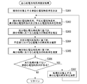
- FIG. 3 is a flowchart showing an example of the flow of the main unit electromotive force time series estimation process of the embodiment.
- a predetermined rule one of the unit electrocardiographic time series generated in step S200 is determined as the target unit electrocardiographic time series (step S301).
- the predetermined rule is, for example, a rule that the unit electrocardiographic time series of the earliest period among the unit electrocardiographic time series acquired in step S200 is determined as the target unit electrocardiographic time series.
- each data of the target unit electrocardiographic time series is one of depolarized electrocardiographic time series data, refractory electrocardiographic time series data, repolarized electrocardiographic time series data, or resting electrocardiographic time series data. Classify into one (step S302).
- the set of data classified into the depolarized electrocardiographic time series data by the process of step S302 is the depolarized electrocardiographic time series.
- the set of data classified into the non-responsive electrocardiographic time series data by the process of step S302 is the non-responsive electrocardiographic potential time series.
- the set of data classified into the repolarized electrocardiographic time series data by the process of step S302 is the repolarized electrocardiographic time series.
- the set of data classified into the resting electrocardiographic time series data by the processing of step S302 is the resting electrocardiographic time series.
- each data of the target unit electrocardiographic time series is divided into depolarizing electrocardiographic time series data, refractory electrocardiographic time series data, repolarizing electrocardiographic time series data, or resting electrocardiographic time series. Any method may be used as long as it can be classified into any one of the data.
- each data of the target unit electrocardiographic time series is divided into depolarizing electrocardiographic time series data, refractory electrocardiographic time series data, repolarizing electrocardiographic time series data, or resting electrocardiographic time series. This is a method of classifying data into any one of them.
- the method of determining the depolarized electrocardiographic time series data is, for example, after determining the start time of the depolarization period and the end time of the depolarization period, the time point indicated by the data is the depolarization period. It is a method of determining whether or not.
- the start time of the period means the start time of the period.
- the end of the period means the end of the period.
- the threshold value is not limited to this value, and may be a value adjusted according to measurement conditions such as the magnitude of the electrocardiogram, skin properties, noise, bioelectrodes, and gain of the measuring device. Further, the end time point of the depolarization period may be, for example, a time point calculated from an inflection point obtained by differentiating the electrocardiographic potential or the like.
- the start time of the refractory period is immediately after the end time of the depolarization period.
- the end point of the refractory period is, for example, the time when the condition that the amount of change in the negative direction of the electrocardiographic potential indicated by the target unit electrocardiographic time series per unit time is equal to or more than a predetermined amount is first satisfied after the start time of the refractory period. ..
- the end point of the refractory period may be, for example, a condition that the absolute value of the amount of change in the electrocardiographic potential is 10 ⁇ V or more.
- the threshold value is not limited to this value, and may be a value adjusted according to measurement conditions such as the magnitude of the electrocardiogram, skin properties, noise, bioelectrodes, and gain of the measuring device.
- the end time point of the refractory period may be, for example, a time point calculated from an inflection point obtained by differentiating the electrocardiographic potential or the like.
- the method of determining the repolarized electrocardiographic time series data is, for example, after determining the start time of the repolarization period and the end time of the repolarization period, the time point indicated by the data is the repolarization period. This is a method for determining whether or not.
- the start time of the repolarization period is immediately after the end time of the refractory period.
- the end time of the repolarization period is, for example, the time when the condition that the absolute value of the change amount of the electrocardiographic potential indicated by the target unit electrocardiographic time series per unit time is less than a predetermined amount is first satisfied after the start time of the repolarization period. Is.
- the absolute value of the change in electrocardiographic potential may be less than 7 ⁇ V.
- the threshold value is not limited to this value, and may be a value adjusted according to measurement conditions such as the magnitude of the electrocardiogram, skin properties, noise, bioelectrodes, and gain of the measuring device.
- the end time point of the repolarization period may be, for example, a time point calculated from an inflection point obtained by differentiating the electrocardiographic potential or the like.
- step S302 the time series of the cardiac electromotive force in the depolarizing period (hereinafter referred to as "depolarized electromotive force time series”) is estimated based on the depolarized electromotive force time series acquired in step S302 (step).
- the depolarized electromotive force time series is data having a depolarized electromotive force estimated value at each time point of the depolarized electromotive force time series.
- the depolarized electromotive force estimate at each time point is an estimated value of the electromotive force at each time point in the depolarization period.
- the depolarized electromotive force estimate is the electrocardiographic potential at the start of the depolarizing period indicated by the depolarized electrocardiographic time series acquired in step S302, and the depolarized electrocardiographic time series acquired in step S302. It is a value obtained by adding the sum of the past depolarization differential potentials indicated by.
- the process of estimating the depolarized electromotive force time series in this way is the process of estimating the electromotive force at each time point in the depolarization period. Specifically, the process of estimating the depolarized electromotive force time series removes the sum of the absolute values of the differences in adjacent electromotive potentials from the start of the depolarizing period to the time corresponding to the electromotive force to be estimated. This is a process of acquiring the value added to the electrocardiographic potential at the start of the polarization period as the electromotive force.
- the non-reactive electromotive force time series is data having an estimated non-reactive electromotive force at each time point of the non-reactive electromotive force time series.
- the refractory electromotive force estimate at each time point is an estimate of the electromotive force at each time point in the refractory period.
- the non-responsive electromotive force estimated value at each time point is a value obtained by subtracting the value related to the electrocardiographic potential at the corresponding time point in the non-responsive electromotive force time series from the value of the depolarized electromotive force estimated value at the end time point.
- the value related to the electrocardiographic potential of the refractory electrocardiographic time series used for subtraction is, for example, the value obtained by subtracting the electrocardiographic potential at the corresponding time point of the refractory electrocardiographic time series from the value of the depolarized electromotive force estimated value at the end point.
- the value related to the electrocardiographic potential in the time series of refractory electrocardiographic potential used for subtraction may be the measured value of the electrocardiographic potential or the absolute value of the electrocardiographic potential. Depending on the electrocardiographic pattern, unnatural deformation such as inversion, folding or bending may occur depending on the positional relationship with the baseline.
- the value related to the refractory electrocardiographic time-series electrocardiographic potential used for the subtraction may be a value obtained by adding a deformation process to the refractory electrocardiographic potential and then subtracting the value.
- adjustments such as adding gain (multiple) and bias (constant), and using accumulation may be performed.
- the corresponding time point is the time point indicated by the non-responsive electromotive force time-series data, and the non-responsive electromotive force time-series data indicating the non-responsive electromotive force estimated value. Is the same time point as indicated by.
- the process of estimating the refractory electromotive force time series in this way is the process of estimating the electromotive force at each time point in the refractory period. Specifically, it is a process of acquiring a value obtained by subtracting a value related to the electromotive potential at the corresponding time point of the refractory period from the estimated value of the electromotive force at the end of the depolarization period as the electromotive force.
- the process of estimating the refractory electromotive force time series is, for example, the process of estimating the electromotive force at each time point in the refractory period. Specifically, it is a process of acquiring a value obtained by subtracting the electromotive potential at the corresponding time point of the refractory period from the estimated value of the electromotive force at the end of the depolarization period as the electromotive force.
- the process of estimating the refractory electromotive force time series for example, the value obtained by subtracting the deformed electromotive potential at the corresponding time in the refractory period from the estimated value of the electromotive force at the end of the depolarization period is acquired as the electromotive force. It may be a process to be performed.
- the value related to the electrocardiographic potential of the refractory electromotive force time series used for subtraction is subtracted from the value of the depolarized electromotive force estimated value at the end time of the electrocardiographic potential at the corresponding time point of the refractory electromotive force time series.
- the method of estimating the electromotive force will be described by taking the case where the values are obtained as an example.
- the process of estimating the refractory electromotive force time series is the process of estimating the refractory electromotive force time series, for example, the process of estimating the cardiac electromotive force at each time point of the refractory period. be.
- the repolarized electromotive force time series in the repolarization period based on the repolarized electromotive force time series acquired in step S302 and the end point refractory electromotive force estimated value acquired in step S304 (hereinafter referred to as "repolarization").
- the polarization electromotive force time series ”) is estimated (step S305).
- the end point refractory electromotive force estimate is the refractory electromotive force estimate at the end of the refractory period.
- the end point refractory electromotive force estimate is consistent with the repolarized electromotive force estimate at the beginning of the repolarization phase.
- the repolarized electromotive force time series is data having an estimated value of the repolarized electromotive force at each time point of the repolarized electromotive force time series.
- the repolarized electromotive force estimate at each time point is an estimated value of the electromotive force at each time point in the repolarization period.
- the repolarized electromotive force estimated value at each time point is the sum of the past repolarized differential potentials indicated by the repolarized electromotive force time series acquired in step S302 from the end point refractory electromotive force estimated value. It is the subtracted value.
- the repolarization phase electrocardiographic potential used for this subtraction is not the absolute value of the above-mentioned electrocardiographic potential, but is adjusted by adding a bias or gain to the above-mentioned absolute value of the electrocardiographic potential, or using accumulation, for example, when crossing the baseline. May be the value at which.
- the electromotive force estimation method will be described by taking as an example the case where the repolarization differential potential is the absolute value of the difference in the electrocardiographic potential between two adjacent time points in the repolarization period.
- step S305 it is determined whether or not the unit electromotive force time series has been estimated for all the unit electromotive force time series generated in step S200 (step S306). That is, it is determined whether or not there is an unestimated unit electrocardiographic time series.
- the unestimated unit electrocardiographic time series is a unit electrocardiographic time series in which the subcardiac electromotive force time series estimation process is not executed.
- the electromotive force estimation method will be described by taking as an example the case where the electrocardiographic time series is the time series of the electrocardiogram generated by one beat of the myocardium. Therefore, the electromotive force series of the estimation result is one unit electromotive potential time series.
- the electrocardiographic time series is estimated by the electromotive force estimation method of the embodiment, taking as an example the case where the electrocardiographic time series is the time series of the electrocardiogram generated by a plurality of beats of the myocardium. An example of the result is shown.
- FIG. 4 is a first explanatory diagram illustrating the certainty of the estimation result by the electromotive force estimation method of the embodiment using the actually measured electrocardiographic time series. More specifically, FIG. 4 shows an example of the electrocardiographic time series of a person whose myocardial movement is normal and before the exercise load test is performed, and the electromotive force estimation method using the electrocardiographic time series. The estimated estimation result is shown.
- the time series D101 in FIG. 4 shows the actually measured electrocardiographic time series.
- the time series D102 in FIG. 4 shows the electromotive force time series estimated by the electromotive force estimation method based on the time series D101.
- the time series D102 of the estimation result has the same characteristics as those medically recognized as the characteristics of the electromotive force time series before the execution of the exercise load test in a person with normal myocardial movement.
- the time series D102 of the estimation result has the characteristics of the action potential of the myocardium having a plateau due to the continuation of the depolarizing potential, and has the characteristics of the waveform of the myocardium observed by monophasic myocardial action potential recording or the like.
- FIG. 4 shows that the method for estimating the electromotive force of the embodiment is a method for estimating the time series of the electromotive force before the execution of the exercise load test of a person whose myocardial movement is normal with high accuracy.
- FIG. 5 is a second explanatory diagram for explaining the certainty of the estimation result by the electromotive force estimation method of the embodiment using the actually measured electrocardiographic time series. More specifically, FIG. 5 shows an example of the electrocardiographic time series of a person who presented with transient ischemia in the myocardium and the estimation result estimated by the electromotive force estimation method using the electrocardiographic time series. ..
- the time series D103 in FIG. 5 shows the actually measured electrocardiographic time series.
- the time series D104 in FIG. 5 shows the electromotive force time series estimated by the electromotive force estimation method based on the time series D103.
- the time series D104 of the estimation result has the same characteristics as those medically recognized as the characteristics of the electromotive force time series during myocardial ischemia. Specifically, it has the characteristics of delayed depolarization, changes such as plateau rise and fall, bending, and extension of action potential duration. Therefore, FIG. 5 shows that the method for estimating the electromotive force is a method for estimating the electromotive force time series at the time of myocardial ischemia with high accuracy.
- FIG. 6 is a third explanatory diagram for explaining the certainty of the estimation result by the electromotive force estimation method of the embodiment using the actually measured electrocardiographic time series. More specifically, FIG. 6 shows an example of the electrocardiographic time series at the time of myocardial ischemia and the estimation result estimated by the electromotive force estimation method using the electrocardiographic time series.
- the time series D105 in FIG. 6 shows the actually measured electrocardiographic time series.
- the time series D106 of FIG. 6 shows the electromotive force time series estimated by the electromotive force estimation method based on the time series D105.
- the time series D106 of the estimation result has the same characteristics as those medically recognized as the characteristics of the electromotive force time series during myocardial ischemia. Specifically, it has the characteristics of delaying depolarization, changes such as plateau rise and fall, bending, and extension of action potential duration. Therefore, FIG. 6 shows that the method for estimating the electromotive force is a method for estimating the electromotive force time series at the time of myocardial ischemia with high accuracy.
- FIG. 7 is a fourth explanatory diagram for explaining the certainty of the estimation result by the electromotive force estimation method of the embodiment using the actually measured electrocardiographic time series. More specifically, FIG. 7 shows an example of the electrocardiographic time series at the time of myocardial ischemia and the estimation result estimated by the electromotive force estimation method using the electrocardiographic time series.
- the time series D107 in FIG. 7 shows the actually measured electrocardiographic time series.
- the time series D108 of FIG. 7 shows the electromotive force time series estimated by the electromotive force estimation method based on the time series D107.
- the time series D108 of the estimation result has the same characteristics as those medically recognized as the characteristics of the electromotive force time series during myocardial ischemia. Specifically, it has the characteristics of delayed depolarization, changes such as plateau rise and fall, bending, and extension of action potential duration. Therefore, FIG. 7 shows that the method for estimating the electromotive force is a method for estimating the electromotive force time series at the time of myocardial ischemia with high accuracy.
- FIG. 8 is a fifth explanatory diagram illustrating the certainty of the estimation result by the electromotive force estimation method of the embodiment using the actually measured electrocardiographic time series. More specifically, FIG. 8 shows an example of the electrocardiographic time series at the time of myocardial ischemia and the estimation result estimated by the electromotive force estimation method using the electrocardiographic time series.
- FIG. 9 is a sixth explanatory diagram illustrating the certainty of the estimation result by the electromotive force estimation method of the embodiment using the actually measured electrocardiographic time series. More specifically, FIG. 9 shows the results of superimposing the time series shown in FIGS. 5, 6, 7, and 8.
- Results E1 to E25 indicate the actually measured electromotive force time series and the electromotive force time series of the estimation results by the electromotive force estimation method, respectively.
- the vertical axis of each graph of Results E1 to E25 indicates the potential.
- the unit of electric potential is microvolts.
- the horizontal axis of each graph of results E1 to E25 indicates the time.
- the unit of time is milliseconds.
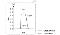
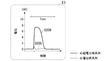
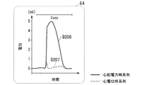
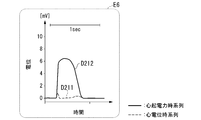
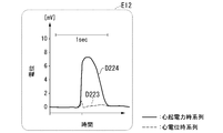
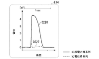
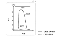
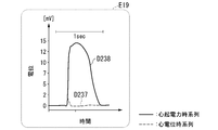
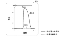
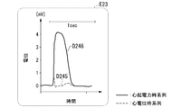
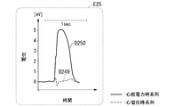
- the time series D201, D203, D205, D207, D209, D211, D213, D215, D217, D219, D221, D223, D225, D227, D229, D231, D233, D235, D237, D239, D241 , D243, D245, D247 and D249 are the measured electrocardiographic time series, respectively.
- the time series D202, D204, D206, D208, D210, D212, D214, D216, D218, D220, D222, D224, D226, D228, D230, D232, D234, D236, D238, D240, D242 , D244, D246, D248 and D250 are the electromotive force time series of the estimation results by the electromotive force estimation method, respectively.
- Time series D202, D204, D206, D208, D210, D212, D214, D216, D218, D220, D222, D224, D226, D228, D230, D232, D234, D236, D238, D240, D242, D244, D246, D248 and All of the D250s have characteristics similar to those medically recognized as the characteristics of the electromotive force time series of a person with normal myocardial movement. Therefore, the results E1 to E25 of FIGS. 10 to 34 show that the method of estimating the electromotive force of the embodiment is a method of estimating the electromotive force time series of a person whose myocardial movement is normal with high accuracy. ..
- FIG. 35 is a 33rd explanatory diagram for explaining the certainty of the estimation result by the electromotive force estimation method of the embodiment using the actually measured electrocardiographic time series.
- FIG. 35 shows the time series D301 and the time series D302.
- the time series D301 is an actually measured electrocardiographic time series.
- the time series D302 is a cardiac electromotive force time series estimated by a cardiac electromotive force estimation method based on the time series D301.
- Time series D301 indicates that extra systoles occur in myocardial movement during the period from time T5 to time T6. Extra systoles in myocardial movement mean that myocardial movement is abnormal. Time series D301 shows that myocardial movement is sinus rhythm at other times. Sinus rhythm of myocardial movement means that myocardial movement is normal.
- Time series D302 indicates that the waveform of the electromotive force during extra systole has a medically known feature.
- the waveform at the time of extra systole is the waveform of the period from time T5 to time T6.
- the characteristics of the electromotive force waveform during extra systole are specifically that the length of the plateau phase (that is, the refractory period) is shorter than that in the normal case, and that the repolarization phase (that is, the repolarization period) is short. ) Is characterized by being earlier than when it is normal.
- FIG. 35 shows that the electromotive force estimation method of the embodiment is a method of estimating the electromotive force time series of a person who has an extra systole with high accuracy.
- FIG. 36 is a thirty-fourth explanatory diagram illustrating the certainty of the estimation result by the electromotive force estimation method of the embodiment using the actually measured electrocardiographic time series.
- FIG. 36 shows the time series D401 and the time series D402.
- the time series D401 is an actually measured electrocardiographic time series.
- the time series D402 is a cardiac electromotive force time series estimated by a cardiac electromotive force estimation method based on the time series D401.
- Time series D401 indicates that extra systoles occur in myocardial movement during the period from time T7 to time T8.
- Time series D401 indicates that extra systoles occur in myocardial movement during the period from time T9 to time T10.
- the time series D402 has a feature that the waveform in the period from time T7 to time T8 is shorter than that when the plateau phase length is normal, and that the start of the repolarized phase is earlier than when it is normal. Shows that it has features. It also shows that the waveform of the time series D402 shows that the waveform of the period from time T7 to time T8 is an abnormality associated with atrioventricular block. Abnormalities associated with atrioventricular block appear in the waveform as a characteristic of QRS complex and ST dysplasia due to ectopic stimulus conduction pathways.
- FIG. 36 shows that the electromotive force estimation method of the embodiment is a method of estimating the electromotive force time series of a person who has an extra systole with high accuracy.
- FIG. 37 is a diagram showing an example of the configuration of the electromotive force estimation system 100 that executes the electromotive force estimation method of the embodiment.
- the electromotive force estimation system 100 includes a cardiac electromotive force estimation device 1 and a electrocardiographic potential measuring device 2.
- the electromotive force estimation device 1 acquires the electrocardiographic time series measured by the electrocardiographic measuring device 2, and estimates the electromotive force time series in the period indicated by the acquired electromotive force time series based on the acquired electrocardiographic time series. ..
- the electrocardiographic potential measuring device 2 measures the electrocardiographic potential of the estimation target in the electromotive force time series.
- the electrocardiographic potential measuring device 2 outputs the electrocardiographic potential time series, which is the time series of the electrocardiographic potential of the measurement result, to the electromotive force estimation device 1.
- the electrocardiographic measuring device 2 is, for example, an electrocardiograph.
- the electromotive force estimation device 1 includes a control unit 10 including a processor 91 such as a CPU (Central Processing Unit) connected by a bus and a memory 92, and executes a program.
- the electromotive force estimation device 1 functions as a device including a control unit 10, a communication unit 11, a storage unit 12, and a user interface 13 by executing a program.
- the processor 91 reads a program stored in the storage unit 12, and stores the read program in the memory 92.
- the electromotive force estimation device 1 functions as a device including the control unit 10, the communication unit 11, the storage unit 12, and the user interface 13.
- the control unit 10 controls the operation of each functional unit included in the electromotive force estimation device 1.
- the control unit 10 controls, for example, the operation of the communication unit 11.
- the control unit 10 controls, for example, the operation of the communication unit 11 to acquire the electrocardiographic time series from the electrocardiographic measuring device 2.
- the control unit 10 records the acquired electrocardiographic time series in the storage unit 12.
- the storage unit 12 is configured by using a storage device such as a magnetic hard disk device or a semiconductor storage device.
- the storage unit 12 stores various information about the electromotive force estimation device 1.
- the storage unit 12 stores, for example, a program for controlling the operation of each functional unit included in the electromotive force estimation device 1 in advance.
- the storage unit 12 stores, for example, a program that executes the electromotive force estimation method in advance.
- the storage unit 12 stores, for example, the electrocardiographic time series of the estimation result.
- the storage unit 12 stores, for example, the electromotive force time series of the estimation result.
- the output unit 132 is a display device such as a liquid crystal display or an organic EL (Electro Luminescence) display.
- the output unit 132 may be configured as, for example, an interface for connecting these display devices to its own device.
- the output unit 132 may be an audio output device such as a speaker.
- the information output by the output unit 132 is, for example, the electromotive force time series of the estimation result.
- the operation of the output unit 132 is controlled by the control unit 10. Therefore, the output unit 132 outputs the estimated electromotive force time series according to the instruction of the control unit 10.
- each data of the electrocardiographic time series is depolarized electrocardiographic time series data, refractory electrocardiographic time series data, repolarization electrocardiographic time series data and pause for each beat. It is classified into any one of four types of electrocardiographic time series data.
- the cardiac electromotive force estimation method estimates the depolarized electromotive force time series based on the depolarized electromotive force time series obtained as a result of classification.
- the depolarized electromotive force time series is data having a depolarized electromotive force estimated value at each time point of the depolarized electromotive force time series.
- the depolarized electromotive force estimate is the sum of the past depolarized differential potentials indicated by the depolarized electrocardiographic time series to the electrocardiographic potential at the start of the depolarized electrocardiographic period indicated by the depolarized electrocardiographic time series. It is the added value.
- the cardiac electromotive force estimation method can estimate the depolarized electromotive force time series by an operation with a smaller calculation load than the estimation simulation method.
- the estimation simulation is a method of estimating the electromotive force by solving the inverse problem by a simulation using a mathematical model that reproduces the electrocardiographic time series.
- the cardiac electromotive force estimation method estimates the non-responsive electromotive force time series based on the non-responsive electromotive force time series obtained as a result of classification.
- the refractory electromotive force time series is data having an estimated value of refractory electromotive force at each time point of the refractory electromotive force time series.
- the non-reactive electromotive force estimate at each time point is the value obtained by subtracting the absolute value of the electromotive force at the corresponding time point in the non-reflexive electromotive force time series from the value of the depolarized electromotive force estimated value at the end time. be.
- the cardiac electromotive force estimation method can estimate the refractory electromotive force time series by an operation with a smaller load than the estimation simulation method.
- the cardiac electromotive force estimation method estimates the repolarized electromotive force time series based on the repolarized electromotive force time series obtained as a result of classification.
- the repolarized electromotive force time series is data having a repolarized electromotive force estimated value at each time point of the repolarized electromotive force time series.
- the repolarized electromotive force estimated value is a value obtained by subtracting the sum of the past repolarized differential potentials indicated by the repolarized electrocardiographic potential time series from the end point refractory electromotive force estimated value.
- the cardiac electromotive force estimation method can estimate the repolarized electromotive force time series by an operation with a smaller load than the estimation simulation method.
- the electromotive force estimation method classifies the electrocardiographic time series into a depolarizing period, a refractory period, a repolarizing period, and a resting period, and estimates the electromotive force for each of the classified data.
- it is necessary to reproduce the electrocardiographic time series in the method of estimating the electromotive force by solving the inverse problem by the simulation using the mathematical model that reproduces the electrocardiographic time series. Therefore, in the simulation using such a mathematical model, all the data of the electrocardiographic time series generated in one beat are required to estimate the electromotive force at one time point.
- the electromotive force estimation method can estimate the electromotive force time series by an operation with a smaller load than the simulation using a mathematical model. Therefore, the electromotive force estimation method can reduce the calculation load when estimating the electromotive force.
- matching processing may be executed for each unit electromotive force time series indicated by the cardiac electromotive force time series.
- the matching process is performed so that the average value of the electromotive force shown by the data in the period after the end of the repolarization period is approximately the same as the average value of the electromotive force shown by the data before the start of the depolarization period. This is a process of multiplying the electromotive force indicated by the data in the period after the end of the polarization period by a constant number.
- FIG. 38 is an explanatory diagram illustrating the effect of the matching process in the modified example.
- FIG. 38 is a diagram showing a cardiac electromotive force time series when the matching process is not executed and a cardiac electromotive force time series after the matching process is executed.
- FIG. 38 shows the electrocardiographic time series D501 and the electromotive force time series D502 in the upper graph.
- the electromotive force time series D502 is a cardiac electromotive force time series estimated by a cardiac electromotive force estimation method based on the electromotive force time series D501, and is a cardiac electromotive force time series in which matching processing is not executed.
- the horizontal axis in the upper graph of FIG. 38 represents time.
- the vertical axis in the upper graph of FIG. 38 represents the electric potential.
- the unit of the vertical axis in the upper graph of FIG. 38 is millivolts.
- FIG. 38 shows the electromotive force time series D503 in the lower graph.
- the electromotive force time series D503 is a cardiac electromotive force time series estimated by a cardiac electromotive force estimation method based on the electromotive force time series D501, and is a cardiac electromotive force time series after the execution of the matching process.
- the horizontal axis in the lower graph of FIG. 38 represents time.
- the vertical axis in the lower graph of FIG. 38 represents the electric potential.
- the unit of the vertical axis in the lower graph of FIG. 38 is millivolts.
- the electromotive force time series D503 shown in the lower graph of FIG. 38 shows that the potential difference between the potential of the peak with a negative potential and the potential indicated by the baseline is smaller than that of the electrocardiographic time series D502.
- the average value of the potentials in the refractory period in the electromotive force time series is not always substantially constant.
- a time series of electromotive force with a substantially constant average value of potentials in the refractory period is acquired.
- FIG. 38 shows that the baseline of the electromotive force time series D503 is more parallel to the baseline of the electromotive force time series D501 than the baseline of the electromotive force time series D502.
- the matching process can increase the degree of parallelism of the electromotive force time series with respect to the baseline in the electromotive force time series compared to the case where the matching process is not performed.
- the graph of the electromotive force time series becomes a graph that is easy for the user to see. Therefore, the user can acquire the content indicated by the electromotive force time series with less effort than when the matching process is not performed.
- the execution of the matching process increases the degree of parallelism of the electromotive force time series with respect to the baseline, so that the graph of the electromotive force time series becomes a graph that is easy for the user to see. Therefore, the user can acquire the content indicated by the electromotive force time series with less effort than when the matching process is not performed.
- the process of acquiring the refractory electromotive force time series is not limited to the process described in this specification.
- the process of acquiring the refractory electromotive force time series is the process of acquiring the deformed refractory electromotive force estimated value as the electromotive force corresponding to each data of the refractory electromotive force time series (hereinafter, "refractory electromotive force"). It may be referred to as "power estimation deformation processing").
- the deformed refractory electromotive force estimated value may be a value obtained by multiplying the electrocardiographic potential indicated by the refractory electromotive force time series by a constant and adding the value of the depolarized electromotive force estimated value at the end point.
- the constant is a value determined according to the height of the repolarized electrocardiographic time series.
- the constant is, for example, 1/100 to 1/200 of the maximum potential of the T wave.
- the constant may be adjusted, for example, by the magnitude of the electrocardiographic potential.
- the waveform in the refractory period indicated by the cardiac electromotive force time series estimated by the cardiac electromotive force estimation method having the refractory electromotive force estimation deformation processing is shown by the cardiac electromotive force time series estimated by the cardiac electromotive force estimation method of the embodiment. It is more complicated than the waveform in the refractory period. The complexity of the waveform means that the amount of information is large. Therefore, the cardiac electromotive force time series estimated by the cardiac electromotive force estimation method having the refractory electromotive force estimation deformation processing has more myocardiums than the cardiac electromotive force time series estimated by the cardiac electromotive force estimation method of the embodiment. Shows information about the operation of.
- the method of estimating the non-reactive electromotive force time series is to use a learned model in which the relationship between the non-reactive electromotive force time series and the non-reactive electromotive force time series has been learned in advance by machine learning. It may be a method of estimating the electromotive force time series.
- the explanatory variable of the trained model is the refractory electromotive force time series
- the dependent variable is the refractory electromotive force time series.
- the machine learning method may be a recurrent neural network or deep learning.
- the method for estimating the depolarized electromotive force time series is not limited to the method described in this specification.
- the method of estimating the depolarized electromotive force time series is estimated using a bijective map showing the correspondence between the depolarized electromotive force time series and the depolarized electromotive force time series acquired in advance. It may be a method of doing.
- the method for estimating the repolarization phase electromotive force time series is not limited to the method described in this specification.
- the method of estimating the repolarization phase electromotive force time series uses a bijective map showing the correspondence between the depolarized electromotive force time series and the depolarized electromotive force time series acquired in advance. It may be an estimation method.
- the process of step S200 is an example of a division step.
- the process of step S302 is an example of the state time series acquisition step.
- the process of step S303 is an example of the depolarization electromotive force estimation step.
- the process of step S304 is an example of the refractory electromotive force estimation step.
- the process of step S305 is an example of the repolarization electromotive force estimation step.
- the communication unit 11 and the input unit 131 are examples of acquisition units, respectively.
- the process of step S200 is an example of the division process.
- the process of step S302 is an example of the state time series acquisition process.
- the process of step S303 is an example of the depolarized electromotive force estimation process.
- the process of step S304 is an example of the refractory electromotive force estimation process.
- the process of step S305 is an example of the repolarized electromotive force estimation process.
- the electromotive force estimation device 1 may be implemented by using a plurality of information processing devices connected so as to be able to communicate via a network.
- each functional unit included in the electromotive force estimation device 1 may be distributed and mounted in a plurality of information processing devices.
- electromotive force estimation system 1 ... electromotive force estimation device, 2 ... electrocardiographic potential measuring device, 10 ... control unit, 11 ... communication unit, 12 ... storage unit, 13 ... user interface
Landscapes
- Health & Medical Sciences (AREA)
- Life Sciences & Earth Sciences (AREA)
- Cardiology (AREA)
- Engineering & Computer Science (AREA)
- Physics & Mathematics (AREA)
- Surgery (AREA)
- Veterinary Medicine (AREA)
- Pathology (AREA)
- Biomedical Technology (AREA)
- Heart & Thoracic Surgery (AREA)
- Medical Informatics (AREA)
- Molecular Biology (AREA)
- Biophysics (AREA)
- Animal Behavior & Ethology (AREA)
- General Health & Medical Sciences (AREA)
- Public Health (AREA)
- Power Engineering (AREA)
- Artificial Intelligence (AREA)
- Evolutionary Computation (AREA)
- Fuzzy Systems (AREA)
- Mathematical Physics (AREA)
- Computer Vision & Pattern Recognition (AREA)
- Physiology (AREA)
- Psychiatry (AREA)
- Signal Processing (AREA)
- Measurement And Recording Of Electrical Phenomena And Electrical Characteristics Of The Living Body (AREA)
Abstract
心起電力の時系列の推定対象の心電位の時系列を、心筋の1回の拍動によって生じる心電位を表す時系列が互いに分離されるように単位心電位時系列に区分するステップと、前記単位心電位時系列ごとに脱分極期に属するデータの集合である脱分極心電位時系列と不応期に属するデータの集合である不応心電位時系列と再分極期に属するデータの集合である再分極心電位時系列とを取得するステップと、脱分極心電位時系列に基づき脱分極期の各時点における心起電力を示す脱分極心起電力時系列を推定するステップと、不応心電位時系列と脱分極期の終了時点における心起電力の推定値とに基づき不応期の各時点における心起電力を示す不応心起電力時系列を推定するステップと、再分極心電位時系列と不応期の終了時点における心起電力の推定値とに基づき再分極期の各時点における心起電力を示す再分極心起電力時系列を推定するステップと、を有する心起電力推定方法。
Description
本発明は、心起電力推定方法、心起電力推定装置及びプログラムに関する。
心筋梗塞や狭心症に代表される心筋虚血による心筋の異常は心筋の膜電位の集合である心起電力の異常として現れることが知られている。また心筋や刺激伝導系の障害、心不全などの心臓への負荷も心起電力に影響を及ぼす。しかしながら、心起電力を直接測定することは難しい。そこで、医療現場では多くの場合心起電力によって生じる体表面の心電位の時系列である心電図を見て心筋の異常を推定する。具体的には、心電位の時系列のP、QRS、ST、Tの各成分部とその間隔の変化を見て心筋の異常を推定する。しかし原信号の心起電力と比較して体表面の心電位は直流成分を中心に著しく減衰するため、心筋の異常によって生じる変化は小さく、そのため異常の検出が困難な場合がある。そこで、心電位の時系列を再現する生物物理、数理モデルを用いたシミュレーションの実行により心起電力を含む心機能を推定する方法が提案されている。
大江 透 「心臓電気生理学的検査(単相性心筋活動電位記録)」 日本循環器学会専門医誌 循環器専門医第28巻 p.129-135 2019年8月
K.H.W.J.ten Tusscher, D.Noble, P.J.Noble, and A.V.Panfilov, "A model for human ventricular tissue", Am J Physiol Heart Circ Physiol. 286:H1573-H1589, 2004
田中 博 「心電図逆問題における方法論」 医用電子と生体工学 1985年 第23巻 第3号 p.147-158
MICHAEL R. FRANZ, "Long-Term Recording of Monophasic Action Potentials From Human Endocardium" Am J Cardiol. 1983 Jun; 51, p.1629-1634
しかしながら、生物物理、数理モデルを用いた非線形有限要素法等のシミュレーションは計算負荷が高く、実測値と整合する際に経験と高度な技術が求められるという問題がある。そのため、高い性能の計算機を用意する必要ということや、結果が得られるまでの時間がかかるなどの問題があった。
また、心筋梗塞や致死的不整脈などの重症な心臓疾患は、異常の発生から死に至る時間が短く、迅速な異常の検知と評価が求められる。しかしながら、従来技術では心起電力を迅速に算出することは困難であったため、体表面の心電位が明確な異常を呈するまで判定することができず、病状が深刻になるという問題があった。
上記事情に鑑み、本発明は、心起電力を推定する際の計算負荷を軽減する技術を提供することを目的としている。
本発明の一態様は、心起電力の時系列の推定対象の心電位時系列を、心筋の1回の拍動によって生じる心電位を表す時系列が互いに分離されるように区分する区分ステップと、前記区分ステップにおいて区分された各時系列を単位心電位時系列として、単位心電位時系列ごとに単位心電位時系列の各データを脱分極期に属するデータと不応期に属するデータと再分極期に属するデータと休止期に属するデータとに分類することで、前記単位心電位時系列ごとに、脱分極期に属するデータの集合である脱分極心電位時系列と不応期に属するデータの集合である不応心電位時系列と再分極期に属するデータの集合である再分極心電位時系列とを取得する状態時系列取得ステップと、前記脱分極心電位時系列に基づき前記脱分極期の各時点における心起電力を示す脱分極心起電力時系列を推定する脱分極心起電力推定ステップと、前記不応心電位時系列と前記脱分極期の終了時点における心起電力の推定値とに基づき前記不応期の各時点における心起電力を示す不応心起電力時系列を推定する不応心起電力推定ステップと、前記再分極心電位時系列と前記不応期の終了時点における心起電力の推定値とに基づき前記再分極期の各時点における心起電力を示す再分極心起電力時系列を推定する再分極心起電力推定ステップと、を有する、心起電力推定方法である。
本発明により、心起電力を推定する際の計算負荷を軽減することが可能となる。
以下、実施形態の心起電力推定方法を、図面を参照して説明する。なお、本発明における「脱分極期」は、心電図におけるQRSと定義した。脱分極期は、心室の心筋細胞の集団における脱分極相及びスパイク(Phase0及びPhase1)に相当する。
また、本発明における「再分極期」は、心電図のTと定義した。再分極期は、心室の心筋細胞の集団における再分極相(Phase3)に相当する。また、本発明における「不応期」は、心電図のSTセグメントと定義した。不応期は、心室の心筋細胞の集団におけるプラトー相(Phase2)に相当する。本発明における「休止期」は、脱分極期、不応期又は再分極期のいずれでもない期間と定義した。休止期は、心室の心筋細胞の集団における静止電位の期間(Phase4)に相当する。
なお、心室の心筋細胞の集団における脱分極期のスパイク(Phase1)については、脱分極期から省略し、代わりに、不応期に含めても良い。
図1は、実施形態の心起電力推定方法の概略を説明する説明図である。心起電力推定方法は、心電位の時系列(以下「心電位時系列」という。)に基づき、推定対象の心電位時系列が示す期間における心起電力の時系列(以下「心起電力時系列」という。)を推定する方法である。推定対象は人であってもよいし動物であってもよい。以下、説明の簡単のため推定対象が人である場合を例に心起電力推定方法を説明する。図1において、時系列A100は、心電位時系列の一例である。図1において心電位の単位はマイクロボルトである。図1において時刻の単位はミリ秒である。
心起電力推定方法では、まず心電位時系列を取得する。心起電力推定法では、取得した心電位時系列を、心筋の1回の拍動によって生じる心電位を表す時系列が互いに分離されるように区分する。心筋の1回の拍動とは、心筋に脱分極が生じた時点から、脱分極期と、不応期と、再分極期とを経て休止期に入るまでの期間における心筋の一連の動作である。
図1において時系列A200は、心筋の1回の拍動によって生じる心電位を表す時系列を含む時系列であって区分後の1つの時系列(以下「単位心電位時系列」という。)の一例である。単位心電位時系列は、例えば、始まりがP波の開始の時点であり終わりが次のP波の開始直前の時点である期間における心電位時系列である。単位心電位時系列は、例えば、P波の検出が困難である場合、基線からR波T波を経て基線に戻るまでという条件を満たす期間における心電位時系列であってもよい。
単位心電位時系列は、脱分極心電位時系列、不応心電位時系列、再分極心電位時系列及び休止心電位時系列を有する。脱分極心電位時系列は、脱分極期に生じた心電位を示す時系列である。不応心電位時系列は、不応期に生じた心電位を示す時系列である。再分極心電位時系列は、再分極期に生じた心電位を示す時系列である。休止心電位時系列は、休止期に生じた心電位を示す時系列である。すなわち休止心電位時系列は、単位心電位時系列が有する各データのうち、脱分極心電位時系列、不応心電位時系列又は再分極心電位時系列のいずれにも属さないデータの集合である。
図1において、時刻T1から時刻T2までの期間における時系列は脱分極心電位時系列の一例である。図1において、時刻T2から時刻T3までの期間における時系列は不応心電位時系列の一例である。図1において、時刻T3から時刻T4までの期間における時系列は再分極心電位時系列の一例である。図1において、時刻T0から時刻T1までの期間における時系列と時刻T4以降の時系列とは休止心電位時系列の一例である。
図1において、時刻T0から時刻T1において単位心電位時系列は略一定である。図1において、時刻T0から時刻T1の期間における時系列A300は、P波を示す時系列である。
心起電力推定法では、単位心電位時系列ごとに各単位心電位時系列が示す期間における心起電力の時系列(以下「単位心起電力時系列」という。)を推定する。具体的には、まず、単位心電位時系列が示す各データを、脱分極心電位時系列に属するデータと、不応心電位時系列に属するデータと、再分極心電位時系列に属するデータと、休止心電位時系列に属するデータとに分類する。
以下、脱分極心電位時系列に属するデータを脱分極心電位時系列データという。以下、不応心電位時系列に属するデータを不応心電位時系列データという。以下、再分極心電位時系列に属するデータを再分極心電位時系列データという。以下、休止心電位時系列に属するデータを休止心電位時系列データという。
次に、脱分極期、不応期及び再分極期の各期間に応じた規則にしたがって心起電力時系列を推定する。以下、図2及び図3を用いて、単位心電位時系列ごとに心起電力の時系列を推定する具体的な推定方法の説明とともに心起電力推定方法を説明する。
図2は、実施形態の心起電力推定方法において実行される処理の流れの一例を示すフローチャートである。心起電力推定方法は、例えばコンピュータが実行する。
心電位時系列を取得する(ステップS100)。次に、取得した心電位時系列を、単位心電位時系列ごとに区分する(ステップS200)。ステップS200の処理は、心電位時系列を単位心電位時系列で区分する処理であるので単位心電位時系列を生成する処理である。
次に、主心起電力時系列推定処理を実行する(ステップS300)。主心起電力時系列推定処理は、ステップS200で生成された全ての単位心電位時系列について各単位心電位時系列が示す期間における単位心起電力時系列を推定する処理である。
主心起電力時系列推定処理は、具体的には、副心起電力時系列推定処理を全ての単位心電位時系列に対して実行する処理である。副心起電力時系列推定処理は、1つの単位心電位時系列に対して実行される処理であって実行対象の単位心電位時系列が示す期間における単位心起電力時系列を推定する処理である。以下、副心起電力時系列推定処理の実行対象の単位心電位時系列を対象単位心電位時系列という。
図3は、実施形態の主単位心起電力時系列推定処理の流れの一例を示すフローチャートである。所定の規則に従い、ステップS200で生成された単位心電位時系列の1つを対象単位心電位時系列に決定する(ステップS301)。所定の規則は、例えば、ステップS200で取得された単位心電位時系列のうち最も早い期間の単位心電位時系列を対象単位心電位時系列に決定する、という規則である。
以下で説明するステップS302からステップS305の処理が副心起電力時系列推定処理の一例である。ステップS301の次に、対象単位心電位時系列の各データを、脱分極心電位時系列データ、不応心電位時系列データ、再分極心電位時系列データ又は休止心電位時系列データのいずれか1つに分類する(ステップS302)。
ステップS302の処理によって脱分極心電位時系列データに分類されたデータの集合が脱分極心電位時系列である。ステップS302の処理によって不応心電位時系列データに分類されたデータの集合が不応心電位時系列である。ステップS302の処理によって再分極心電位時系列データに分類されたデータの集合が再分極心電位時系列である。ステップS302の処理によって休止心電位時系列データに分類されたデータの集合が休止心電位時系列である。
このように、ステップS302の処理は、脱分極心電位時系列、不応心電位時系列、再分極心電位時系列及び休止心電位時系列を取得する処理である。
対象単位心電位時系列分類方法は、対象単位心電位時系列の各データを、脱分極心電位時系列データ、不応心電位時系列データ、再分極心電位時系列データ又は休止心電位時系列データのいずれか1つに分類できればどのような方法であってもよい。対象単位心電位時系列分類方法は、対象単位心電位時系列の各データを、脱分極心電位時系列データ、不応心電位時系列データ、再分極心電位時系列データ又は休止心電位時系列データのいずれか1つに分類する方法である。
対象単位心電位時系列分類方法において脱分極心電位時系列データを判定する方法は例えば、脱分極期の開始時点と脱分極期の終了時点とを判定した後、データの示す時点が脱分極期か否かを判定する方法である。期間の開始時点は期間の開始の時点を意味する。期間の終了時点は期間の終了の時点を意味する。
脱分極期の開始時点は例えば、対象単位心電位時系列の示す心電位の単位時間当たりの変化量が所定の量以上という条件を最初に満たした時点である。脱分極期の開始時点は、例えば、200Hzサンプリング周波数の場合、単位時間5msec当たりの心電位の変化量の絶対値が40μボルト以上という条件であってもよい。閾値はこの値に限らず心電位の大きさや皮膚の性状、生体電極、計測機器の利得などの計測条件によって調整された値であってもよい。また、脱分極期の開始時点は、例えば、心電位の微分等によって求めた変曲点から算出された時点であってもよい。
脱分極期の終了時点は例えば、脱分極の開始時点以降の時点であって、対象単位心電位時系列の示す心電位の時間軸正方向の傾きの符号が少なくとも1回反転した後に対象単位心電位時系列の示す心電位の変化量が初めて所定の閾値を下回った時点である。脱分極期の終了時点は、例えば、単位時間5msec当たりの心電位の変化量の絶対値が30μボルト以下という条件であってもよい。閾値はこの値に限らず心電位の大きさや皮膚の性状、雑音、生体電極、計測機器の利得などの計測条件によって調整された値であってもよい。また、脱分極期の終了時点は、例えば、心電位の微分等によって求めた変曲点から算出された時点であってもよい。
対象単位心電位時系列分類方法において不応心電位時系列データを判定する方法は例えば、不応期の開始時点と不応期の終了時点とを判定した後、データの示す時点が不応期か否かを判定する方法である。
不応期の開始時点は、脱分極期の終了時点の直後の時点である。不応期の終了時点は例えば、対象単位心電位時系列の示す心電位の単位時間当たりの負方向の変化量が所定の量以上という条件を不応期の開始時点以降に最初に満たした時点である。不応期の終了時点は、例えば、心電位の変化量の絶対値が10μボルト以上という条件であってもよい。閾値はこの値に限らず心電位の大きさや皮膚の性状、雑音、生体電極、計測機器の利得などの計測条件によって調整された値であってもよい。また、不応期の終了時点は、例えば、心電位の微分等によって求めた変曲点から算出された時点であってもよい。
対象単位心電位時系列分類方法において再分極心電位時系列データを判定する方法は例えば、再分極期の開始時点と再分極期の終了時点とを判定した後、データの示す時点が再分極期か否かを判定する方法である。
再分極期の開始時点は、不応期の終了時点の直後の時点である。再分極期の終了時点は例えば、対象単位心電位時系列の示す心電位の単位時間当たりの変化量の絶対値が所定の量未満という条件を再分極期の開始時点以降に最初に満たした時点である。再分極期の終了時点は、心電位の変化量の絶対値が7μボルト未満であってもよい。閾値はこの値に限らず心電位の大きさや皮膚の性状、雑音、生体電極、計測機器の利得などの計測条件によって調整された値であってもよい。また、再分極期の終了時点は、例えば、心電位の微分等によって求めた変曲点から算出された時点であってもよい。
ステップS302の次に、ステップS302で取得された脱分極心電位時系列に基づき、脱分極期における心起電力の時系列(以下「脱分極心起電力時系列」という。)を推定する(ステップS303)。脱分極心起電力時系列は、脱分極心電位時系列の時点ごとに脱分極心起電力推定値を有するデータである。各時点の脱分極心起電力推定値は、脱分極期の各時点における心起電力の推定値である。
脱分極心起電力推定値は具体的には、ステップS302で取得された脱分極心電位時系列が示す脱分極期の開始時点の心電位に、ステップS302で取得された脱分極心電位時系列が示す過去の脱分極差分電位の総和を足し算した値である。
脱分極差分電位は、脱分極期における隣接する2つの時点間の心電位の差の絶対値である。なお、過去の脱分極差分電位は、異なる単位心電位時系列における脱分極差分電位は含まない。そのため、過去の脱分極差分電位とは、脱分極期の開始時点以降の過去の脱分極差分電位である。
このように脱分極心起電力時系列を推定する処理は、脱分極期の時点ごとに各時点における心起電力を推定する処理である。具体的には、脱分極心起電力時系列を推定する処理は、脱分極期の開始時点から推定対象の心起電力に対応する時点までの隣接する心電位の差の絶対値の総和を脱分極期の開始時点における心電位に足し算した値を心起電力として取得する処理である。
ステップS303の次に、ステップS302で取得された不応心電位時系列とステップS303で取得された終了時点脱分極心起電力推定値とに基づき不応期における心起電力の時系列(以下「不応心起電力時系列」という。)を推定する(ステップS304)。終了時点脱分極心起電力推定値は、脱分極期の終了時点における脱分極心起電力推定値である。
不応心起電力時系列は、不応心電位時系列の時点ごとに不応心起電力推定値を有するデータである。各時点の不応心起電力推定値は、不応期の各時点における心起電力の推定値である。各時点の不応心起電力推定値は具体的には、終了時点脱分極心起電力推定値の値から不応心電位時系列の対応する時点における心電位に関する値を引き算した値である。
引き算に用いる不応心電位時系列の心電位に関する値は、例えば、終了時点脱分極心起電力推定値の値から不応心電位時系列の対応する時点における心電位を引き算した値である。引き算に用いる不応心電位時系列の心電位に関する値は、心電位の実測値または、心電位の絶対値であってもよい。心電位のパターンによっては、基線との位置関係により、反転や折り返しや屈曲などの不自然な変形を生じる場合がある。そのような場合、引き算に用いる不応心電位時系列の心電位に関する値は、不応期心電位に変形処理を加えてから引き算した値であっても良い。この変形では、ゲイン(倍数)やバイアス(定数)を加える、累積を用いるなどの調整が行われてもよい。なお、不応心起電力推定値の定義における、対応する時点とは、不応心電位時系列データが示す時点であって、不応心起電力推定値を示す不応心起電力時系列データが示す時点に同一の時点である。
このように不応心起電力時系列を推定する処理は、不応期の時点ごとに各時点における心起電力を推定する処理である。具体的には、脱分極期の終了時点における心起電力の推定値から不応期の対応する時点における心電位に関する値を引き算した値を心起電力として取得する処理である。
不応心起電力時系列を推定する処理は、例えば、不応期の時点ごとに各時点における心起電力を推定する処理である。具体的には、脱分極期の終了時点における心起電力の推定値から不応期の対応する時点における心電位を引き算した値を心起電力として取得する処理である。不応心起電力時系列を推定する処理は、例えば、脱分極期の終了時点における心起電力の推定値から不応期の対応する時点における変形した心電位を引き算した値を心起電力として取得する処理であってもよい。
以下、説明の簡単のため、引き算に用いる不応心電位時系列の心電位に関する値が終了時点脱分極心起電力推定値の値から不応心電位時系列の対応する時点における心電位を引き算した値である場合を例に、心起電力推定方法を説明する。このような場合、不応心起電力時系列を推定する処理は、不応心起電力時系列を推定する処理は、例えば、不応期の時点ごとに各時点における心起電力を推定する処理である。
ステップS304の次に、ステップS302で取得された再分極心電位時系列とステップS304で取得された終了時点不応心起電力推定値に基づき再分極期における心起電力の時系列(以下「再分極心起電力時系列」という。)を推定する(ステップS305)。終了時点不応心起電力推定値は、不応期の終了時点における不応心起電力推定値である。終了時点不応心起電力推定値は再分極期の開始時点における再分極心起電力推定値に一致する。
再分極心起電力時系列は、再分極心電位時系列の時点ごとに再分極心起電力推定値を有するデータである。各時点における再分極心起電力推定値は、再分極期の各時点における心起電力の推定値である。各時点における再分極心起電力推定値は具体的には、終了時点不応心起電力推定値から、ステップS302で取得された再分極心電位時系列が示す過去の再分極差分電位の総和を引き算した値である。
再分極差分電位は、再分極期における隣接する2つの時点間の心電位の差に基づく値である。再分極差分電位は、例えば、再分極期における隣接する2つの時点間の心電位の差の絶対値である。なお、過去の再分極差分電位は、異なる単位心電位時系列における再分極差分電位は含まない。そのため、過去の再分極差分電位とは、不応期の終了時点以降の過去の再分極差分電位である。この引き算に用いる再分極期心電位は、例えば基線と交差する場合などに、上述の心電位の絶対値ではなく、上述の心電位の絶対値にバイアスやゲインを加える、累積を用いるなどの調整が行われた値であってもよい。以下、説明の簡単のため、再分極差分電位が再分極期における隣接する2つの時点間の心電位の差の絶対値である場合を例に、心起電力推定方法を説明する。
このように再分極心起電力時系列を推定する処理は、再分極期の時点ごとに各時点における心起電力を推定する処理である。具体的には、再分極心電位時系列における不応期の終了時点から、推定される心起電力に対応する時点まで、の隣接する心電位の差の絶対値の総和を不応期の終了時点における心起電力の推定値から引き算した値を心起電力として取得する処理である。
ステップS302からステップS305の一連の処理の1回の実行によって推定された脱分極心起電力時系列、不応心起電力時系列及び再分極心起電力時系列の集合が、対象単位心電位時系列が示す期間における推定された単位心起電力時系列である。
ステップS305の次に、ステップS200で生成された全ての単位心電位時系列について単位心起電力時系列を推定したか否かを判定する(ステップS306)。すなわち、未推定単位心電位時系列が無いか否かを判定する。未推定単位心電位時系列は、副心起電力時系列推定処理が実行されていない単位心電位時系列である。
未推定単位心電位時系列がある場合(ステップS306:YES)、所定の規則に則り、未推定単位心電位時系列のうちの1つを対象単位心電位時系列に決定する(ステップS307)。所定の規則は、例えば、未推定単位心電位時系列のうちの最も早い期間の未推定単位心電位時系列を対象単位心電位時系列に決定する、という規則である。ステップS307の次に、ステップS302に戻る。一方、未推定単位心電位時系列が無い場合(ステップS306:NO)、処理を終了する。
図1の説明に戻る。ステップS300の処理によって推定された各単位心起電力時系列の集合を、ステップS100で取得された心電位時系列が示す期間における心起電力時系列の推定結果として取得する(ステップS400)。
以下、図4~図34を用いて実施形態の心起電力推定方法による推定結果の確からしさの検証結果を、実測された心電位時系列を用いて説明する。図4~図34の説明においては説明の簡単のため、心電位時系列が心筋の1回の拍動によって生じる心電位の時系列である場合を例に心起電力推定方法を説明する。そのため、推定結果の心起電力系列は、1つの単位心電位時系列である。
また図35及び図36を用い、心電位時系列が心筋の複数回の拍動によって生じる心電位の時系列である場合を例に、実施形態の心起電力推定方法による心電位時系列の推定結果の一例を示す。
なお、図4~図36の説明における実測された心電位時系列は、PhysioNet(https://physionet.org/about/database/#ecg)に公開されているデータである。
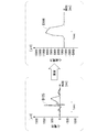
図4は、実施形態の心起電力推定方法による推定結果の確からしさを、実測された心電位時系列を用いて説明する第1の説明図である。より具体的には、図4は心筋の動作が正常な人であって運動負荷試験が行われる前の人の心電位時系列の一例とその心電位時系列を用いて心起電力推定方法によって推定した推定結果とを示す。
図4の時系列D101は、実測された心電位時系列を示す。図4の時系列D102は、時系列D101に基づき心起電力推定方法によって推定された心起電力時系列を示す。推定結果の時系列D102は、心筋の動作が正常な人の運動負荷試験実行前の心起電力時系列が有する特徴として医学的に認知されている特徴と同様の特徴を備える。具体的には、推定結果の時系列D102は、脱分極電位の持続によるプラトーを有する心筋の活動電位の特徴を備え、単相性心筋活動電位記録等で観測される心筋の波形の特徴を具備している(非特許文献1及び4参照)。そのため、図4は、実施形態の心起電力推定方法について、心筋の動作が正常な人の運動負荷試験実行前の心起電力時系列を高い精度で推定する方法であることを示す。
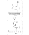
図5は、実施形態の心起電力推定方法による推定結果の確からしさを、実測された心電位時系列を用いて説明する第2の説明図である。より具体的には、図5は心筋に一過性の虚血を呈した人の心電位時系列の一例とその心電位時系列を用いて心起電力推定方法によって推定した推定結果とを示す。
図5の時系列D103は、実測された心電位時系列を示す。図5の時系列D104は、時系列D103に基づき心起電力推定方法によって推定された心起電力時系列を示す。推定結果の時系列D104は、心筋の虚血時の心起電力時系列が有する特徴として医学的に認知されている特徴と同様の特徴を備える。具体的には、脱分極の遅延、プラトーの上昇や下降、屈曲などの変化、活動電位持続時間の延長の特徴を備える。そのため、図5は、心起電力推定方法について、心筋の虚血時の心起電力時系列を高い精度で推定する方法であることを示す。
図6は、実施形態の心起電力推定方法による推定結果の確からしさを、実測された心電位時系列を用いて説明する第3の説明図である。より具体的には、図6は心筋の虚血時の心電位時系列の一例とその心電位時系列を用いて心起電力推定方法によって推定した推定結果とを示す。
図6の時系列D105は、実測された心電位時系列を示す。図6の時系列D106は、時系列D105に基づき心起電力推定方法によって推定された心起電力時系列を示す。推定結果の時系列D106は、心筋の虚血時の心起電力時系列が有する特徴として医学的に認知されている特徴と同様の特徴を備える。具体的には、脱分極の遅延、プラトーの上昇や下降、屈曲などの変化、活動電位持続時間の延長特徴を備える。そのため、図6は、心起電力推定方法について、心筋の虚血時の心起電力時系列を高い精度で推定する方法であることを示す。
図7は、実施形態の心起電力推定方法による推定結果の確からしさを、実測された心電位時系列を用いて説明する第4の説明図である。より具体的には、図7は心筋の虚血時の心電位時系列の一例とその心電位時系列を用いて心起電力推定方法によって推定した推定結果とを示す。
図7の時系列D107は、実測された心電位時系列を示す。図7の時系列D108は、時系列D107に基づき心起電力推定方法によって推定された心起電力時系列を示す。推定結果の時系列D108は、心筋の虚血時の心起電力時系列が有する特徴として医学的に認知されている特徴と同様の特徴を備える。具体的には、脱分極の遅延、プラトーの上昇や下降、屈曲などの変化、活動電位持続時間の延長の特徴を備える。そのため、図7は、心起電力推定方法について、心筋の虚血時の心起電力時系列を高い精度で推定する方法であることを示す。
図8は、実施形態の心起電力推定方法による推定結果の確からしさを、実測された心電位時系列を用いて説明する第5の説明図である。より具体的には、図8は心筋の虚血時の心電位時系列の一例とその心電位時系列を用いて心起電力推定方法によって推定した推定結果とを示す。
図8の時系列D109は、実測された心電位時系列を示す。図8の時系列D110は、時系列D109に基づき心起電力推定方法によって推定された心起電力時系列を示す。推定結果の時系列D110は、心筋の虚血時の心起電力時系列が有する特徴として医学的に認知されている特徴と同様の特徴を備える。具体的には、脱分極の遅延、プラトーの上昇や下降、屈曲などの変化、活動電位持続時間の延長の特徴を備える。そのため、図8は、心起電力推定方法について、心筋の虚血時の心起電力時系列を高い精度で推定する方法であることを示す。
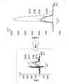
図9は、実施形態の心起電力推定方法による推定結果の確からしさを、実測された心電位時系列を用いて説明する第6の説明図である。より具体的には、図9は、図5、図6、図7及び図8に示す時系列を重ねて表示した結果を示す。
図9は、縦軸が電位を示し横軸が時刻を示す。縦軸が示す電位は、時系列D103、D105、D107及びD109については心電位を示し、時系列D104、D106、D108及びD110については心起電力を示す。
図9は、心起電力推定方法によって推定された2つの心起電力時系列が示す各形状には、心電位時系列の違いを反映した違いがあることを示す。具体的には、図9は、心起電力時系列間には不応期における電位差があり、心電位時系列にも不応期における電位差があることを示す。また、図9の不応期における違いは、心起電力時系列間の違いの方が心電位時系列間における違いよりも大きい。そのため、図9は、心電位時系列間の違いを増幅した違いが心起電力時系列間の違いとして現れることを示す。
図10~図34を用いて、実施形態の心起電力推定方法による推定結果の確からしさを説明する。図10~図34は、それぞれ実施形態の心起電力推定方法による推定結果の確からしさを、実測された心電位時系列を用いて説明する第7~第31の説明図である。より具体的には、図10~図34の各結果はそれぞれ、心筋の動作が正常な人の心電位時系列とその心電位時系列を用いて心起電力推定方法によって推定した推定結果とを示す例である。
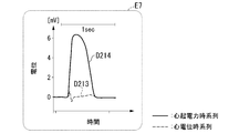
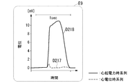
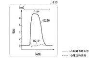
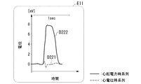
図10~図34は、結果E1~結果E25を示す。結果E1~結果E25はそれぞれ、実測された心電位時系列と心起電力推定方法による推定結果の心起電力時系列とを示す。結果E1~結果E25の各グラフの縦軸は電位を示す。電位の単位はマイクロボルトである。結果E1~結果E25の各グラフの横軸は時刻を示す。時刻の単位はミリ秒である。
図10~図34において、時系列D201、D203、D205、D207、D209、D211、D213、D215、D217、D219、D221、D223、D225、D227、D229、D231、D233、D235、D237、D239、D241、D243、D245、D247及びD249はそれぞれ実測された心電位時系列である。
図10~図34において、時系列D202、D204、D206、D208、D210、D212、D214、D216、D218、D220、D222、D224、D226、D228、D230、D232、D234、D236、D238、D240、D242、D244、D246、D248及びD250はそれぞれ心起電力推定方法による推測結果の心起電力時系列である。
時系列D202、D204、D206、D208、D210、D212、D214、D216、D218、D220、D222、D224、D226、D228、D230、D232、D234、D236、D238、D240、D242、D244、D246、D248及びD250はいずれも心筋の動作が正常な人の心起電力時系列が有する特徴として医学的に認知されている特徴と同様の特徴を備える。そのため、図10~図34の結果E1~結果E25は、実施形態の心起電力推定方法について、心筋の動作が正常な人の心起電力時系列を高い精度で推定する方法であることを示す。
図35は、実施形態の心起電力推定方法による推定結果の確からしさを、実測された心電位時系列を用いて説明する第33の説明図である。図35は時系列D301及び時系列D302を示す。時系列D301は実測された心電位時系列である。時系列D302は時系列D301に基づき心起電力推定方法によって推定された心起電力時系列である。
時系列D301は、時刻T5から時刻T6までの期間に心筋の動作に期外収縮が起きていることを示す。心筋の動作に期外収縮が起きているとは、心筋の動作が異常であることを意味する。時系列D301は、それ以外の期間では心筋の動作が洞調律であることを示す。心筋の動作が洞調律であるとは、心筋の動作が正常であることを意味する。
時系列D302は、期外収縮時の心起電力の波形に医学的に知られた特徴が生じていることを示す。時系列D302において期外収縮時の波形は、時刻T5から時刻T6までの期間の波形である。期外収縮時の心起電力の波形の特徴は、具体的には、プラトー相(すなわち不応期)の長さが正常の場合に比較して短いという特徴と、再分極相(すなわち再分極期)の開始が正常の場合に比較して早いという特徴とである。
このように図35は、実施形態の心起電力推定方法について、期外収縮を生じている人の心起電力時系列を高い精度で推定する方法であることを示す。
図36は、実施形態の心起電力推定方法による推定結果の確からしさを、実測された心電位時系列を用いて説明する第34の説明図である。図36は時系列D401及び時系列D402を示す。時系列D401は実測された心電位時系列である。時系列D402は時系列D401に基づき心起電力推定方法によって推定された心起電力時系列である。
時系列D401は、時刻T7から時刻T8までの期間に心筋の動作に期外収縮が起きていることを示す。時系列D401は、時刻T9から時刻T10までの期間に心筋の動作に期外収縮が起きていることを示す。
時系列D402は、時刻T7から時刻T8までの期間の波形が、プラトー相の長さが正常の場合に比較して短いという特徴と、再分極相の開始が正常の場合に比較して早いという特徴とを有することを示す。また、時系列D402の波形は時刻T7から時刻T8までの期間の波形が、房室ブロックに伴う異常であることも示す。房室ブロックに伴う異常は、異所性の刺激伝導路によるQRS波やSTの異形性という特徴として波形に現れている。
時系列D402は、時刻T9から時刻T10までの期間の波形が、プラトー相の長さが正常の場合に比較して短いという特徴と、再分極相の開始が正常の場合に比較して早いという特徴とを有することを示す。また、時系列D402の波形は時刻T7から時刻T8までの期間の波形が、房室ブロックに伴う異常であることも示す。房室ブロックに伴う異常は、異所性の刺激伝導路によるQRS波やSTの異形性という特徴として波形に現れている。
このように、時系列D402は、時刻T7から時刻T8までの期間の波形に、房室ブロックに伴う期外収縮時の心起電力の波形の医学的に知られた特徴が生じていることを示す。また、時系列D402は、時刻T9から時刻T10までの期間の波形に、房室ブロックに伴う期外収縮時の心起電力の波形の医学的に知られた特徴が生じていることを示す。
このように図36は、実施形態の心起電力推定方法について、期外収縮を生じている人の心起電力時系列を高い精度で推定する方法であることを示す。
図37は、実施形態の心起電力推定方法を実行する心起電力推定システム100の構成の一例を示す図である。心起電力推定システム100は、心起電力推定装置1及び心電位測定装置2を備える。心起電力推定装置1は、心電位測定装置2が測定した心電位時系列を取得し、取得した心電位時系列に基づき取得した心電位時系列が示す期間における心起電力時系列を推定する。
心電位測定装置2は、心起電力時系列の推定対象の心電位を測定する。心電位測定装置2は、測定結果の心電位の時系列である心電位時系列を心起電力推定装置1に出力する。心電位測定装置2は、例えば、心電計である。
心起電力推定装置1は、バスで接続されたCPU(Central Processing Unit)等のプロセッサ91とメモリ92とを備える制御部10を備え、プログラムを実行する。心起電力推定装置1は、プログラムの実行によって制御部10、通信部11、記憶部12及びユーザインタフェース13を備える装置として機能する。
より具体的には、心起電力推定装置1は、プロセッサ91が記憶部12に記憶されているプログラムを読み出し、読み出したプログラムをメモリ92に記憶させる。プロセッサ91が、メモリ92に記憶させたプログラムを実行することによって、心起電力推定装置1は、制御部10、通信部11、記憶部12及びユーザインタフェース13を備える装置として機能する。
制御部10は、心起電力推定装置1が備える各機能部の動作を制御する。制御部10は例えば通信部11の動作を制御する。制御部10は、例えば通信部11の動作を制御して、心電位測定装置2から心電位時系列を取得する。制御部10は取得した心電位時系列を記憶部12に記録する。
制御部10は例えば、心起電力推定方法を用いて、心起電力時系列を推定する。より具体的には、制御部10は、通信部11又はユーザインタフェース13を介して入力された心電位時系列を取得し、取得した心電位時系列に基づき心起電力推定方法によって心電位時系列が示す期間における心起電力時系列を推定する。制御部10は取得した心起電力時系列を記憶部12に記録する。
制御部10は例えば、出力部132の動作を制御して、出力部132に推定結果の心起電力時系列を出力させる。
通信部11は、心電位測定装置2を含む1又は複数の外部装置に心起電力推定装置1を接続するための通信インタフェースを含んで構成される。外部装置の1つは心電位測定装置2である。通信部11は、心電位測定装置2から心電位時系列を取得する。外部装置の1つは、例えば、推定結果の心起電力時系列を出力するプリンタである。このような場合、通信部11は外部装置の1つであるプリンタに推定結果の心起電力時系列を送信する。
記憶部12は、磁気ハードディスク装置や半導体記憶装置などの記憶装置を用いて構成される。記憶部12は心起電力推定装置1に関する各種情報を記憶する。記憶部12は例えば、心起電力推定装置1が備える各機能部の動作を制御するプログラムを予め記憶する。記憶部12は例えば、予め心起電力推定方法を実行するプログラムを記憶する。記憶部12は例えば、推定結果の心電位時系列を記憶する。記憶部12は例えば、推定結果の心起電力時系列を記憶する。
ユーザインタフェース13は、心起電力推定装置1に対する入力を受け付ける入力部131と心起電力推定装置1に関する各種情報を表示する出力部132とを備える。ユーザインタフェース13は、例えば、タッチパネルである。入力部131は、自装置に対する入力を受け付ける。入力部131は、例えばマウスやキーボード、タッチパネル等の入力端末である。入力部131は、例えば、これらの入力端末を自装置に接続するインタフェースとして構成されてもよい。入力部131が受け付ける入力は、例えば、心起電力の推定の開始を指示する入力である。入力部131が受け付ける入力は、例えば、心電位時系列であってもよい。
出力部132は、例えば液晶ディスプレイ、有機EL(Electro Luminescence)ディスプレイ等の表示装置である。出力部132は、例えば、これらの表示装置を自装置に接続するインタフェースとして構成されてもよい。出力部132は、例えばスピーカー等の音声出力装置であってもよい。出力部132が出力する情報は、例えば、推定結果の心起電力時系列である。出力部132の動作は制御部10によって制御される。そのため、出力部132は制御部10の指示にしたがって推定結果の心起電力時系列を出力する。
このように構成された心起電力推定方法は、心電位時系列の各データを拍動ごとに脱分極心電位時系列データ、不応心電位時系列データ、再分極心電位時系列データ及び休止心電位時系列データの4種類のいずれか1つに分類する。
心起電力推定方法は、分類の結果得られる脱分極心電位時系列に基づき、脱分極心起電力時系列を推定する。上述したように、脱分極心起電力時系列は、脱分極心電位時系列の時点ごとに脱分極心起電力推定値を有するデータである。上述したように、脱分極心起電力推定値は、脱分極心電位時系列が示す脱分極期の開始時点の心電位に、脱分極心電位時系列が示す過去の脱分極差分電位の総和を足し算した値である。
そのため心起電力推定方法は、推定シミュレーション法よりも計算負荷の小さい演算によって脱分極心起電力時系列を推定することができる。推定シミュレーションは、心電位時系列を再現する数理モデルを用いたシミュレーションにより逆問題を解くことで心起電力を推定する方法である。
心起電力推定方法は、分類の結果得られる不応心電位時系列に基づき、不応心起電力時系列を推定する。上述したように、不応心起電力時系列は、不応心電位時系列の時点ごとに不応心起電力推定値を有するデータである。上述したように、各時点の不応心起電力推定値は、終了時点脱分極心起電力推定値の値から不応心電位時系列の対応する時点における心電位の絶対値を引き算した値である。
そのため心起電力推定方法は、推定シミュレーション法よりも負荷の小さな演算によって不応心起電力時系列を推定することができる。
心起電力推定方法は、分類の結果得られる再分極心電位時系列に基づき、再分極心起電力時系列を推定する。上述したように、再分極心起電力時系列は、再分極心電位時系列の時点ごとに再分極心起電力推定値を有するデータである。上述したように、再分極心起電力推定値は、終了時点不応心起電力推定値から、再分極心電位時系列が示す過去の再分極差分電位の総和を引き算した値である。
そのため心起電力推定方法は、推定シミュレーション法よりも負荷の小さな演算によって再分極心起電力時系列を推定することができる。
このように、心起電力推定方法は心電位時系列を脱分極期、不応期、再分極期及び休止期に分類し、分類したデータごとに心起電力を推定する。ところで、心電位時系列を再現する数理モデルを用いたシミュレーションにより逆問題を解くことで心起電力を推定する方法は心電位時系列を再現する必要がある。そのためこのような数理モデルを用いたシミュレーションでは、1つの時点の心起電力を推定するために1つの拍動で生じた心電位時系列の全データを必要とする。
一方、心起電力推定方法であれば、1つの時点の心起電力を推定するためには必ずしも心電位時系列の全てを必要としない。例えば脱分極期の心起電力の推定は、脱分極期の心起電力のデータさえあれば可能である。このように、心起電力推定方法は、数理モデルを用いたシミュレーションよりも負荷の小さな演算によって心起電力時系列を推定することができる。そのため、心起電力推定方法は心起電力を推定する際の計算負荷を軽減することができる。
(変形例)
心起電力推定方法では、心起電力時系列が示す各単位心起電力時系列に対して一致処理を実行してもよい。一致処理は、再分極期の終了時点以降の期間におけるデータが示す心起電力の平均値が脱分極期の開始時点以前のデータが示す心起電力の平均値に略一致であるように、再分極期の終了時点以降の期間におけるデータが示す心起電力を定数倍する処理である。
心起電力推定方法では、心起電力時系列が示す各単位心起電力時系列に対して一致処理を実行してもよい。一致処理は、再分極期の終了時点以降の期間におけるデータが示す心起電力の平均値が脱分極期の開始時点以前のデータが示す心起電力の平均値に略一致であるように、再分極期の終了時点以降の期間におけるデータが示す心起電力を定数倍する処理である。
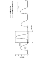
図38は、変形例における一致処理が奏する効果を説明する説明図である。図38は、一致処理が未実行の場合における心起電力時系列と一致処理の実行後の心起電力時系列とを示す図である。
図38は、上段のグラフに心電位時系列D501と心起電力時系列D502とを示す。心起電力時系列D502は、心電位時系列D501に基づき心起電力推定方法によって推定された心起電力時系列であって一致処理が実行されていない心起電力時系列である。図38の上段のグラフにおける横軸は時刻を表す。図38の上段のグラフにおける縦軸は電位を表す。図38の上段のグラフにおける縦軸の単位はミリボルトである。
図38は、下段のグラフに心起電力時系列D503を示す。心起電力時系列D503は、心電位時系列D501に基づき心起電力推定方法によって推定された心起電力時系列であって一致処理の実行後の心起電力時系列である。図38の下段のグラフにおける横軸は時刻を表す。図38の下段のグラフにおける縦軸は電位を表す。図38の下段のグラフにおける縦軸の単位はミリボルトである。
図38の上段のグラフは、心起電力時系列D502における電位が負のピークの電位と基線が示す電位との電位差を示す。具体的には、図38の上段のグラフにおける電位差W1、電位差W2、電位差W3及び電位差W4が、心起電力時系列D502における電位が負のピークの電位と基線が示す電位との電位差である。
図38の下段のグラフが示す心起電力時系列D503は、心電位時系列D502に比べて電位が負のピークの電位と基線が示す電位との電位差が小さいことを示す。
このように、一致処理が行われない場合、心起電力時系列における不応期の電位の平均値は必ずしも略一定ではない。一方、一致処理の実行により不応期の電位の平均値が略一定の心起電力時系列が取得される。
また、図38は、心起電力時系列D503の基線は心起電力時系列D502の基線よりも心電位時系列D501の基線に対する平行の度合が高いことを示す。
このように、一致処理は、心起電力時系列における心電位時系列の基線に対する平行の度合を一致処理が行われない場合よりも高くすることができる。
このように一致処理の実行により不応期の電位の平均値が略一定になるため心起電力時系列のグラフはユーザにとって見やすいグラフになる。そのため、ユーザは、一致処理が行われない場合よりも少ない労力で心起電力時系列が示す内容を取得することができる。
また、一致処理の実行により、心起電力時系列における心電位時系列の基線に対する平行の度合が高まるため、心起電力時系列のグラフはユーザにとって見やすいグラフになる。そのため、ユーザは、一致処理が行われない場合よりも少ない労力で心起電力時系列が示す内容を取得することができる。
なお不応期心起電力時系列を取得する処理は、本明細書に記載の処理に限らない。例えば、不応期心起電力時系列を取得する処理は、不応心電位時系列の各データに対応する心起電力として変形不応心起電力推定値を取得する処理(以下「不応心起電力推定変形処理」という。)であってもよい。例えば、変形不応心起電力推定値は、不応心電位時系列が示す心電位に定数を乗算した値を終了時点脱分極心起電力推定値の値に足し算した値であってもよい。定数は再分極心電位時系列の高さに応じて定まる値である。定数は例えば、T波最大電位の100分の1から200分の1である。定数は、例えば、心電位の大きさによって調整されてもよい。
不応心起電力推定変形処理を有する心起電力推定方法によって推定された心起電力時系列が示す不応期における波形が実施形態の心起電力推定方法によって推定された心起電力時系列が示す不応期における波形よりも複雑である。波形が複雑であることは、情報量が多いことを意味する。そのため、不応心起電力推定変形処理を有する心起電力推定方法によって推定された心起電力時系列は、実施形態の心起電力推定方法によって推定された心起電力時系列よりも多くの心筋の動作に関する情報を示す。
なお、不応心起電力時系列を推定する方法は、予め機械学習によって不応心電位時系列と不応心起電力時系列との関係を学習済みの学習済みモデルを用いて、不応心起電力時系列を推定する方法であってもよい。このような場合、学習済みモデルの説明変数は不応心電位時系列であり、従属変数は不応心起電力時系列である。機械学習の方法は、再帰型ニューラルネットワークであっても、深層学習であってもよい。
なお、脱分極心起電力時系列を推定する方法は、本明細書に記載の方法に限らない。例えば、脱分極心起電力時系列を推定する方法は、予め取得済みの脱分極心電位時系列と脱分極心起電力時系列との間の対応関係を示す全単射の写像を用いて推定する方法であってもよい。
なお、再分極期心起電力時系列を推定する方法は、本明細書に記載の方法に限らない。例えば、再分極期心起電力時系列を推定する方法は、予め取得済みの脱分極心電位時系列と脱分極心起電力時系列との間の対応関係を示す全単射の写像を用いて推定する方法であってもよい。
なお、ステップS200の処理は、区分ステップの一例である。ステップS302の処理は、状態時系列取得ステップの一例である。ステップS303の処理は、脱分極心起電力推定ステップの一例である。ステップS304の処理は、不応心起電力推定ステップの一例である。ステップS305の処理は、再分極心起電力推定ステップの一例である。
通信部11又は入力部131はそれぞれ取得部の一例である。ステップS200の処理は、区分処理の一例である。ステップS302の処理は、状態時系列取得処理の一例である。ステップS303の処理は、脱分極心起電力推定処理の一例である。ステップS304の処理は、不応心起電力推定処理の一例である。ステップS305の処理は、再分極心起電力推定処理の一例である。
心起電力推定装置1は、ネットワークを介して通信可能に接続された複数台の情報処理装置を用いて実装されてもよい。この場合、心起電力推定装置1が備える各機能部は、複数の情報処理装置に分散して実装されてもよい。
なお、心起電力推定装置1の各機能の全て又は一部は、ASIC(Application Specific Integrated Circuit)やPLD(Programmable Logic Device)やFPGA(Field Programmable Gate Array)、PRC(Physical Reservoir Computing)等のハードウェアを用いて実現されてもよい。プログラムは、コンピュータ読み取り可能な記録媒体に記録されてもよい。コンピュータ読み取り可能な記録媒体とは、例えばフレキシブルディスク、光磁気ディスク、ROM、CD-ROM等の可搬媒体、コンピュータシステムに内蔵されるハードディスク等の記憶装置である。プログラムは、電気通信回線を介して送信されてもよい。
以上、この発明の実施形態について図面を参照して詳述してきたが、具体的な構成はこの実施形態に限られるものではなく、この発明の要旨を逸脱しない範囲の設計等も含まれる。
100…心起電力推定システム、1…心起電力推定装置、2…心電位測定装置、10…制御部、11…通信部、12…記憶部、13…ユーザインタフェース
Claims (10)
- 心起電力の時系列の推定対象の心電位の時系列を、心筋の1回の拍動によって生じる心電位を表す時系列が互いに分離されるように区分する区分ステップと、
前記区分ステップにおいて区分された各時系列を単位心電位時系列として、単位心電位時系列ごとに単位心電位時系列の各データを脱分極期に属するデータと不応期に属するデータと再分極期に属するデータと休止期に属するデータとに分類することで、前記単位心電位時系列ごとに、脱分極期に属するデータの集合である脱分極心電位時系列と不応期に属するデータの集合である不応心電位時系列と再分極期に属するデータの集合である再分極心電位時系列とを取得する状態時系列取得ステップと、
前記脱分極心電位時系列に基づき前記脱分極期の各時点における心起電力を示す脱分極心起電力時系列を推定する脱分極心起電力推定ステップと、
前記不応心電位時系列と前記脱分極期の終了時点における心起電力の推定値とに基づき前記不応期の各時点における心起電力を示す不応心起電力時系列を推定する不応心起電力推定ステップと、
前記再分極心電位時系列と前記不応期の終了時点における心起電力の推定値とに基づき前記再分極期の各時点における心起電力を示す再分極心起電力時系列を推定する再分極心起電力推定ステップと、
を有する、心起電力推定方法。 - 前記脱分極心起電力推定ステップにおいて前記脱分極心起電力時系列に含まれる心起電力を推定する場合、前記脱分極期の開始時点から、推定される心起電力に対応する時点まで、の隣接する心電位の差の絶対値の総和を前記開始時点における心電位に足し算した値を心起電力として取得する、
請求項1に記載の心起電力推定方法。 - 前記脱分極心起電力推定ステップでは、予め取得済みの脱分極心電位時系列と脱分極心起電力時系列との間の対応関係を示す全単射の写像を用いて前記推定対象の脱分極心起電力時系列を推定する、
請求項1に記載の心起電力推定方法。 - 前記再分極心起電力推定ステップにおいて前記再分極心起電力時系列に含まれる心起電力を推定する場合、前記再分極心電位時系列における前記不応期の終了時点から、推定される心起電力に対応する時点まで、の隣接する心電位の差に基づく値の総和を前記終了時点における心起電力の推定値から引き算した値を心起電力として取得する、
請求項1から3のいずれか一項に記載の心起電力推定方法。 - 前記再分極心起電力推定ステップでは、予め取得済みの再分極心電位時系列と再分極心起電力時系列との間の対応関係を示す全単射の写像を用いて前記推定対象の再分極心起電力時系列を推定する、
請求項1から3のいずれか一項に記載の心起電力推定方法。 - 前記不応心起電力推定ステップにおいて前記不応心起電力時系列に含まれる心起電力を推定する場合、前記脱分極期の終了時点における心起電力の推定値から前記不応期の対応する時点における心電位に関する値を引き算した値を心起電力として取得する、
請求項1から5のいずれか一項に記載の心起電力推定方法。 - 前記不応心起電力推定ステップにおいて推定する各時点の心起電力は、予め機械学習によって不応心電位時系列と不応心起電力時系列との関係を学習済みの学習済みモデルを用いて推定された値である、
請求項1から5のいずれか一項に記載の心起電力推定方法。 - 前記不応心起電力推定ステップにおいて前記不応心起電力時系列に含まれる心起電力を推定する場合、前記不応心電位時系列が示す心電位に定数を乗算した値を前記脱分極期の終了時点における心起電力の推定値の値に足し算した値を心起電力として取得する、
請求項1から5のいずれか一項に記載の心起電力推定方法。 - 心起電力の時系列の推定対象の心電位の時系列である心電位時系列を取得する取得部と、
前記心電位時系列を、心筋の1回の拍動によって生じる心電位を表す時系列が互いに分離されるように区分する区分処理と、前記区分処理によって区分された各時系列を単位心電位時系列として、単位心電位時系列ごとに単位心電位時系列の各データを脱分極期に属するデータと不応期に属するデータと再分極期に属するデータと休止期に属するデータとに分類することで、前記単位心電位時系列ごとに、脱分極期に属するデータの集合である脱分極心電位時系列と不応期に属するデータの集合である不応心電位時系列と再分極期に属するデータの集合である再分極心電位時系列とを取得する状態時系列取得処理と、前記脱分極心電位時系列に基づき前記脱分極期の各時点における心起電力を示す脱分極心起電力時系列を推定する脱分極心起電力推定処理と、前記不応心電位時系列と前記脱分極期の終了時点における心起電力の推定値とに基づき前記不応期の各時点における心起電力を示す不応心起電力時系列を推定する不応心起電力推定処理と、前記再分極心電位時系列と前記不応期の終了時点における心起電力の推定値とに基づき前記再分極期の各時点における心起電力を示す再分極心起電力時系列を推定する再分極心起電力推定処理と、を実行する制御部と、
を備える心起電力推定装置。 - 請求項9に記載の心起電力推定装置としてコンピュータを機能させるためのプログラム。
Priority Applications (3)
| Application Number | Priority Date | Filing Date | Title |
|---|---|---|---|
| PCT/JP2020/010025 WO2021181465A1 (ja) | 2020-03-09 | 2020-03-09 | 心起電力推定方法、心起電力推定装置及びプログラム |
| US17/909,716 US20240206796A1 (en) | 2020-03-09 | 2020-03-09 | Heart's electromotive force estimation method, heart's electromotive force estimation apparatus and program |
| JP2022507004A JP7406164B2 (ja) | 2020-03-09 | 2020-03-09 | 心起電力推定方法、心起電力推定装置及びプログラム |
Applications Claiming Priority (1)
| Application Number | Priority Date | Filing Date | Title |
|---|---|---|---|
| PCT/JP2020/010025 WO2021181465A1 (ja) | 2020-03-09 | 2020-03-09 | 心起電力推定方法、心起電力推定装置及びプログラム |
Publications (1)
| Publication Number | Publication Date |
|---|---|
| WO2021181465A1 true WO2021181465A1 (ja) | 2021-09-16 |
Family
ID=77670479
Family Applications (1)
| Application Number | Title | Priority Date | Filing Date |
|---|---|---|---|
| PCT/JP2020/010025 Ceased WO2021181465A1 (ja) | 2020-03-09 | 2020-03-09 | 心起電力推定方法、心起電力推定装置及びプログラム |
Country Status (3)
| Country | Link |
|---|---|
| US (1) | US20240206796A1 (ja) |
| JP (1) | JP7406164B2 (ja) |
| WO (1) | WO2021181465A1 (ja) |
Citations (1)
| Publication number | Priority date | Publication date | Assignee | Title |
|---|---|---|---|---|
| JP2017164164A (ja) * | 2016-03-15 | 2017-09-21 | 国立大学法人滋賀医科大学 | 心筋興奮判別装置 |
Family Cites Families (1)
| Publication number | Priority date | Publication date | Assignee | Title |
|---|---|---|---|---|
| EP3721794B1 (en) * | 2014-02-27 | 2022-02-23 | Zoll Medical Corporation | Vcg vector loop bifurcation |
-
2020
- 2020-03-09 US US17/909,716 patent/US20240206796A1/en not_active Abandoned
- 2020-03-09 WO PCT/JP2020/010025 patent/WO2021181465A1/ja not_active Ceased
- 2020-03-09 JP JP2022507004A patent/JP7406164B2/ja active Active
Patent Citations (1)
| Publication number | Priority date | Publication date | Assignee | Title |
|---|---|---|---|---|
| JP2017164164A (ja) * | 2016-03-15 | 2017-09-21 | 国立大学法人滋賀医科大学 | 心筋興奮判別装置 |
Non-Patent Citations (3)
| Title |
|---|
| MASHIMA, SABURO: "Certain basic problems of electrocardiography", JAPANESE JOURNAL OF ELECTROCARDIOGRAPHY, vol. 1, no. 2, pages 117 - 125 * |
| MASHIMA, SABURO: "Concept and Applications of Ventricular Gradients. Heart", VENTRICULAR GRADIENT, vol. 1, no. 10, 1969, pages 1003 - 1012 * |
| TSUTSUMI, KEN ET AL.: "Action Potential Duration Differences and T Waves for Each Intraventricular Area", JAPANESE JOURNAL OF ELECTROCARDIOGRAPHY, vol. 9, no. 1, 1989, pages 3 - 16 * |
Also Published As
| Publication number | Publication date |
|---|---|
| US20240206796A1 (en) | 2024-06-27 |
| JP7406164B2 (ja) | 2023-12-27 |
| JPWO2021181465A1 (ja) | 2021-09-16 |
Similar Documents
| Publication | Publication Date | Title |
|---|---|---|
| KR102154652B1 (ko) | 순환신경망을 이용한 구간혈압 추정 방법 및 그 방법을 구현하기 위한 구간 혈압 추정 장치 | |
| Mincholé et al. | Quantification of Restitution Dispersion From the Dynamic Changes of the $ T $-Wave Peak to End, Measured at the Surface ECG | |
| CN109044348A (zh) | 房颤检测装置及存储介质 | |
| CN109843165B (zh) | 心跳检测方法和心跳检测设备 | |
| CN110740681A (zh) | 用于估计患者的脑血容量和/或脑血流量和/或麻醉深度的系统和方法 | |
| WO2017150156A1 (ja) | 心拍検出方法および心拍検出装置 | |
| US20190298213A1 (en) | Method and system for predicting heart tissue activation | |
| JP7406164B2 (ja) | 心起電力推定方法、心起電力推定装置及びプログラム | |
| JP6764830B2 (ja) | 不整脈判定装置、不整脈判定方法および不整脈判定処理プログラム | |
| JP6203554B2 (ja) | 感性状態判定装置及び感性状態判定用コンピュータプログラム | |
| CN109044338B (zh) | 房颤检测装置及存储介质 | |
| Erem et al. | Spatiotemporal estimation of activation times of fractionated ECGs on complex heart surfaces | |
| Tsukada et al. | Tensor cardiography: A novel ECG analysis of deviations in collective myocardial action potential transitions based on point processes and cumulative distribution functions | |
| JP2020075009A (ja) | 生体信号処理装置およびその制御方法 | |
| JP7727249B2 (ja) | 学習装置、情報提供装置、学習方法、情報提供方法及びプログラム | |
| Zhang et al. | Modeling the relationship between concurrent epicardial action potentials and bipolar electrograms | |
| CN116615144B (zh) | 信号解析装置、信号解析方法和程序 | |
| Takha et al. | Optimization of Parameters of coupled ordinary differential equations for ECG Signal Generation using Grey Wolf Optimizer | |
| Zia et al. | Localizing placement of cardiomechanical sensors during dynamic periods via template matching | |
| EP4541280A1 (en) | Signal compositing device, signal compositing method, and program | |
| JP7553839B2 (ja) | 信号解析装置、信号解析方法及びプログラム | |
| US20240032842A1 (en) | Electrode placement method and wearing device | |
| Vinurajkumar et al. | Analysis of ventricular Tachycardia by predicting the QTI instability using ARMAX modelling Technique | |
| Robson | Modelling and Estimation of Spatiotemporal Cardiac Electrical Dynamics | |
| Scholar | Bradycardia & Tachycardia Disease Classification Using ECG Signal Based On GA & ANN Classification |
Legal Events
| Date | Code | Title | Description |
|---|---|---|---|
| ENP | Entry into the national phase |
Ref document number: 2022507004 Country of ref document: JP Kind code of ref document: A |
|
| WWE | Wipo information: entry into national phase |
Ref document number: 17909716 Country of ref document: US |
|
| NENP | Non-entry into the national phase |
Ref country code: DE |
|
| 122 | Ep: pct application non-entry in european phase |
Ref document number: 20924578 Country of ref document: EP Kind code of ref document: A1 |